

Page 1

SERVICE MANUAL
DOCUMENTATION TECHNIQUE
TECHNISCHE DOKUMENTATION
DOCUMENTAZIONE TECNICA
DOCUMENTACION TECNICA
No copying, translation, modification on other use authorized. All rights reserved worldwide. • Tous droits de reproduction, de traduction, d'adaptation et d'exécution réservés pour tous les pays. • Sämtliche Urheberrechte an diesen Texten und Zeichnungen stehen uns zu. Nachdrucke,
Vervielfältigungen - auch auszugsweise - nur mit unserer vorherigen Zustimmung zulässig. Alle Rechte vorbehalten. • I diritti di riproduzione, di traduzione, e esecuzione sono riservati per tutti i paesi. • Derechos de reproduccion, de traduccion, de adaptacion y de ejecucion reservados para todos los paises.
WARNING : Before servicing this chassis please read the safety recommendations.
ATTENTION : Avant toute intervention sur ce châssis, lire les recommandations de sécurité.
ACHTUNG : Vor jedem Eingriff auf diesem Chassis, die Sicherheitsvorschriften lesen.
ATTENZIONE : Prima di intervenire sullo chassis, leggere le norme di sicurezza.
IMPORTANTE : Antes de cualquier intervención, leer las recomendaciones de seguridad.
- 1004 - IFC228 PLASMA
37PB220S4 - 37PB220S4U
42PS220S4 - 42PB220S4U
TV
Plasma
Page 2

Indicates critical safety components, and identical components should be used for replacement. Only then can the
operational safety be garanteed.
Le remplacement des éléments de sécurité (repérés avec le symbole ) par des composants non homologués selon la
Norme CEI 65 entraine la non-conformité de l'appareil. Dans ce cas, la responsabilité du fabricant n'est plus engagée.
Wenn Sicherheitsteile (mit dem Symbol gekennzeichnet) nicht durch Original - Ersatzteile ersetzt werden, erlischt die
Haftung des Herstellers.
La sostituzione dei componenti di sicurezza (evidenziati con il segno ) con componenti non omologati secondo la
norma CEI 65 comporta la non conformitá dell'apparecchio. In tal caso è "esclusa la responsabilità " del costruttore.
La sustitución de elementos de seguridad (marcados con el simbolo ) por componentes no homologados segun la
norma CEI 65, provoca la no conformidad del aparato. En ese caso, el fabricante cesa de ser responsable.
MEASUREMENT CONDITIONS - CONDITIONS DE MESURES - MESSBEDINGUNGEN
CONDIZIONI DI MISURA - CONDICIONES DE MEDIDAS
RICEVITORE :
In UHF, livello d'entrata 1 mV, monoscopio barre :
- PAL, norma G. bianco 100%.
Via SCART, livello d'entrata 1 Vpp, monoscopio barre :
Colore, Contrasto, Luminositá media, Suono minimo.
Programma selezionato PR 01.
Tensioni continue rilevate rispetto alla massa con un voltmetro digitale.
RECEIVER :
On UHF,input level : 1 mV, bar test pattern :
- PAL, I standard, 100% white.
Via the scart socket, input level : 1 Vpp, bar test pattern :
Colour, contrast and brightness at mid-position, sound at minimum.
Programme selected : PR 01.
DC voltages measured between the point and earth using a digital
voltmeter.
EMPFÄNGER :
Bei UHF Eingangspegel 1 mV, Farbbalken :
- PAL, Norm G, Weiss 100%.
Über die Scartbuchse : Eingangspegel 1 Vss, Farbbalken :
Farbe, Kontrast, Helligkeit in der Mitte des Bereichs, Ton auf Minimum.
Zugeordnetes Programm PR 01.
Gleichspannungen mit einem digitalen Voltmeter zur Masse gemessen.
RECEPTEUR :
En UHF, niveau d'entrée 1 mV mire de barres
- SECAM, Norm L, Blanc 100%.
Par la prise Péritélévision, niveau d'entrée 1 Vcc, mire de barres .
Couleur, contraste, lumière à mi-course, son minimum.
Programme affecté PR 01.
Tensions continues relevées par rapport à la masse avec un
voltmètre numérique.
RECEPTOR :
En UHF, nivel de entrada 1 mV, mira de barras :
- PAL, norma G, blanco 100%.
Por la toma Peritelevision, nivel de entrada 1 Vpp mira de barra.
Color, Contraste, luz a mitad de carrera, Sonido minimo.
Programa afectado PR 01.
Tensiones continuas marcadas en relacion a la masa con un voltimetro digital.
Do not disconnect modules when they are energized!
Repairs on power supply section are to be carried out only with isolating transformer.
Ne pas retirer les modules lorsqu' ils sont sous tension. N'effectuer les travaux de maintenance sur la partie reliée
au secteur (Switch Mode) qu'au travers d'un transformateur d'isolement.
Module nicht bei eingeschaltetem Gerät entfernen!
Servicearbeiten am Netzteil nur unter Verwendung eines Regeltrenntrafos durchführen.
Non scollegare le piastre quando sono alimentate!
Per le riparazioni sulla sezione alimentatore, utilizzare un trasformatore isolatore.
No desconectar los módulos cuando están activados. Las reparaciones en la sección de alimentación de energía
deben ser ejecutadas solamente con un transformador de separación.
MAIN
FRANÇAIS ESPAÑOLDEUTSCHENGLISH ITALIANO
1
2
3
4
5
6
7
8
9
10
11
12
13
14
15
16
17
18
19
20
21
NC
21
17
19
15
13
20
18
16
14
12
11
9
10
8
7
5
3
1
6
4
2
NC
AUDIO "R"
AUDIO "R"
AUDIO "L"
NOTE :
... etc. identifies each
pcb module.
AUDIO "D"
AUDIO "D"
AUDIO "G"
AUDIO
"BLEU"
AUDIO "G" MONO
"BLEU"
COMMUT. LENTE
"VERT"
"VERT"
"ROUGE"
COMMUT. RAPIDE
COMMUT. RAPIDE
VIDEO
VIDEO SYNCHRO
BLINDAGE PRISE
AUDIO "R"
AUDIO "R"
AUDIO "L"
AUDIO
"BLAU"
AUDIO "L" MONO
"BLAU"
AV
UMSCHALTUNG
"GRÜN"
"GRÜN"
"ROT"
AUSTASTUNG
AUSTASTUNG
VIDEO
VIDEO ODER
SYNCHRO
ABSCHIRMUNG
DES STECKERS
AUDIO "D"
AUDIO "D"
AUDIO "I"
AUDIO
"AZUL"
AUDIO "I" MONO
AZUL
"CONMUTACION
LENTA"
"VERDE"
"VERDE"
"ROJA"
"CONMUTACION
RAPIDA"
"CONMUTACION
RAPIDA"
VIDEO
VIDEO O SINCRO
BLINDAJE
DEL ENCHUFE
AUDIO "D"
AUDIO "D"
AUDIO "S"
AUDIO
"BLU"
AUDIO "S" MONO
BLU
"COMMUTAZIONE
LENTA"
"VERDE"
"VERDE"
"ROSSO"
"COMMUTAZIONE
RAPIDA"
"COMMUTAZIONE
RAPIDA"
VIDEO
VIDEO O SINCRO
INVOLUCRO METAL-
LICO DELLA PRESA
AUDIO "L" MONO
"BLUE"
"GREEN"
AV LINK AV LINK AV LINK AV LINK AV LINK
"GREEN"
"RED"
"ROUGE" "ROT" "ROJA""ROSSO""RED"
SLOW SWITCH
FAST SWITCH
VIDEO
VIDEO VIDEO VIDEOVIDEOVIDEO
PLUG SCREEN
BOX
VIDEO OR "SYNC"
FAST SWITCH
AUDIO
"BLUE"
: OUTPUT - SORTIE - AUSGANG - USCITA - SALIDA •
: EARTH - MASSE - MASSE - MASSA - MASA
MAIN
NOTE :
... etc. repères des
platines constituant l'appareil.
MAIN
NOTA :
... etc. marcas de las
placas que constituyen el
aparato.
MAIN
NOTA :
... ecc. sigla delle
piastre dell' apparecchio.
MAIN
HINWEIS :
... usw. Kennzeichnung
der Platinen, aus denen das
Gerät zusammengesetzt ist.
: INPUT - ENTRÉE - EINGANG - ENTRATA - ENTRADA •
Page 3

IFC228 PLASMA
First issue 10 / 04 3
Page
SAFETY PRECAUTIONS . . . . . . . . . . . . . . . . . . . . . . . . . . . . . . . . . . . . . . . . . . . . . . . . . . . . . . . . . . 4
ADJUSTMENTS
Service Mode . . . . . . . . . . . . . . . . . . . . . . . . . . . . . . . . . . . . . . . . . . . . . . . . . . . . . . . . . . . . . . . . . 6
Tube / Feature setup . . . . . . . . . . . . . . . . . . . . . . . . . . . . . . . . . . . . . . . . . . . . . . . . . . . . . . . . . . . 8
Video . . . . . . . . . . . . . . . . . . . . . . . . . . . . . . . . . . . . . . . . . . . . . . . . . . . . . . . . . . . . . . . . . . . . . . . 9
Event history / Sound . . . . . . . . . . . . . . . . . . . . . . . . . . . . . . . . . . . . . . . . . . . . . . . . . . . . . . . . . . 10
Miscellaneous / Soft version . . . . . . . . . . . . . . . . . . . . . . . . . . . . . . . . . . . . . . . . . . . . . . . . . . . . . 11
BLOCK DIAGRAM . . . . . . . . . . . . . . . . . . . . . . . . . . . . . . . . . . . . . . . . . . . . . . . . . . . . . . . . . . . . . . .12
SCHEMATIC DIAGRAMS
Main . . . . . . . . . . . . . . . . . . . . . . . . . . . . . . . . . . . . . . . . . . . . . . . . . . . . . . . . . . . . . . . . . . . . . . 12
Power supply . . . . . . . . . . . . . . . . . . . . . . . . . . . . . . . . . . . . . . . . . . . . . . . . . . . . . . . . . . . . . . . . 39
Scaler . . . . . . . . . . . . . . . . . . . . . . . . . . . . . . . . . . . . . . . . . . . . . . . . . . . . . . . . . . . . . . . . . . . . . 43
PRINTED CIRCUIT BOARD
Main . . . . . . . . . . . . . . . . . . . . . . . . . . . . . . . . . . . . . . . . . . . . . . . . . . . . . . . . . . . . . . . . . . . . . . 51
Power supply . . . . . . . . . . . . . . . . . . . . . . . . . . . . . . . . . . . . . . . . . . . . . . . . . . . . . . . . . . . . . . . . 55
Scaler . . . . . . . . . . . . . . . . . . . . . . . . . . . . . . . . . . . . . . . . . . . . . . . . . . . . . . . . . . . . . . . . . . . . . 63
Keyboard . . . . . . . . . . . . . . . . . . . . . . . . . . . . . . . . . . . . . . . . . . . . . . . . . . . . . . . . . . . . . . . . . . . 67
CONTENTS
Page 4
IFC228 PLASMA
4 First issue 10 /04
IMPORTANT SAFETY PRECAUTIONS
1. Before returning an instrument to the customer, always make a safety check of the entire instrument, including the
following items, but not limited to them.
a. Be sure that no built-in protective devices are defective and/or have been defeated during servicing. (1) Protective
shields are provided on this chassis to protect both the technician and the customer. Correctly replace all missing
protective shields, including any removed for servicing convenience. (2) When reinstalling the chassis and/or other
assembly in the cabinet, be sure to put back in place all protective devices, including, but not limited to, non-metallic
control knobs, insulating fishpapers, adjustment and compartment covers/shields, and isolation resistor/capacitor
networks. Do not operate this instrument or permit it to be operated without all protective devices correctly
installed and functioning.
b. Be sure that there are no cabinet openings through which an adult or child might be able to insert their fingers and
contact a hazardous voltage. Such opening include, but are not limited to (1) spacing between the picture tube and
the cabinet mask, (2) excessively wide cabinet ventilation slots, and (3) an improperly fitted and/or incorrectly
secured cabinet back cover.
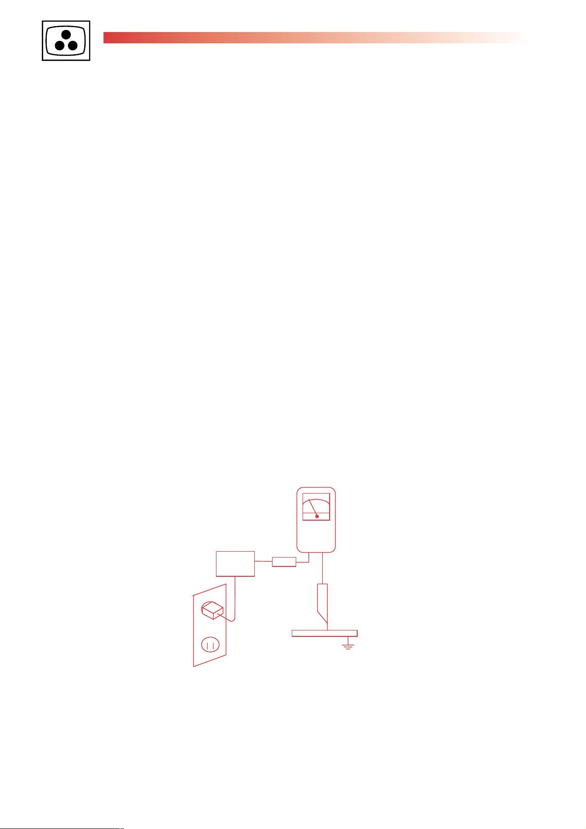
c. Leakage Current Hot Check: With the instrument completely reassembled, plug the AC line cord directly into a 230V
AC outlet. (Do not use an isolation transformer during this test.) Use a leakage current tester or a metering system.
With the instrument AC, first switch ON and then OFF. Measure from a known earth ground (metal waterpipe,
conduit, etc.) to all exposed metal parts of the instrument (antennas, handle bracket, metal cabinet, screwheads,
metallic overlays, control shafts, etc.), especially any exposed metal parts that offer an electrical return path to the
chassis. Any current measured must not exceed 3.5 mA. Reverse the instrument power cord plug in the outlet and
repeat test. ANY MEASUREMENTS NOT WITHIN THE LIMITS SPECIFIED HEREIN INDICATE A POTENTIAL
SHOCK HAZARD THAT MUST BE ELIMINATED BEFORE RETURNING THE INSTRUMENT TO THE
CUSTOMER.
2. Read and comply with all caution and safety-related notes on or inside the Monitor cabinet, on the Projection Monitor
chassis or on the picture tube.
+-
Test all exposed
metal surfaces
3. Wire cord
Also test with
plug reversed
(using AC adapter
plug as required)
Device
under
test
Earth ground
Leakage
current
tester
AC Leakage test
(Reading
should not
be above
3.5 mA)
Page 5

IFC228 PLASMA
First issue 10 / 04 5
3. Design Alteration Warning: Do not alter or add to the mechanical or electrical design of this unit. Design alterations and
additions, including, but not limited to, circuit modifications and the addition of the items such as auxiliary audio and/or
video output connections might alter the safety characteristics of this Projection Monitor and create a hazard to the user.
Any design alterations or additions will void the manufacturer's warranty and will make you, the service, responsible for
personal injury or property damage resulting therefrom.
4. Hot Chassis Warning:
a. Some Monitor chassis are electrically connected directly to one conductor of the AC power cord and may be safely
serviced without an isolation transformer only if the AC power plug is inserted so that the chassis is connected to the
ground side of the AC power source. To confirm that the AC power plug is inserted correctly, with an AC voltmeter
measure between the chassis and a known earth ground. If a voltage reading in excess of 1.0V is obtained, remove
and reinsert the AC power plug in opposite polarity and again measure the voltage potential between the chassis
and a known earth ground.
b. Some Monitor chassis normally have 85V AC (RMS.), between chassis and earth ground regardless of the AC plug
polarity. These chassis can be safely serviced only with an isolation transformer inserted in the power line between
the receiver and the AC power source, for both personnel and test equipment protection.
c. Some Projection Monitor chassis have a secondary ground system in addition to the main chassis ground. This
secondary ground system is not isolated from the AC power line. Insulating material that must not be defeated or
altered electrically separates the two ground systems.
5. Observe original lead dress. Take extra care to assure correct lead dress in the following areas:
a. near sharp edges,
b. near thermally hot parts (be sure that leads and components do not touch thermally hot parts),
c. the AC supply,
d. high voltage,
e. antenna wiring. Always inspect in all areas for pinched, out-of-place, or frayed wiring. Do not change spacing
between components and between components and the printed-circuit board. Check AC powers cord for damage.
6. Components, parts, and/or wiring that appear to have overheated or are otherwise damaged should be replaced with
components, parts, or wiring that meet original specifications. Additionally, determine the cause of overheating and/or
damage and, if necessary, take corrective action to remove any potential safety hazard.
7. PRODUCT SAFETY NOTICE: Many Monitor electrical and mechanical parts have special safety-related characteristics
some of which are often not evident from visual inspection, nor can the protection they give necessarily be obtained by
replacing them with components rated for higher voltage, wattage, etc. Parts that have special safety characteristics are
identified in this service data by shading with a mark on schematics. Use of a substitute replacement part that does not
have the same safety characteristics as the recommended replacement part in this service data parts list might create
shock, fire, and/or other hazards.
Page 6

IFC228 PLASMA
6 First issue 10 /04
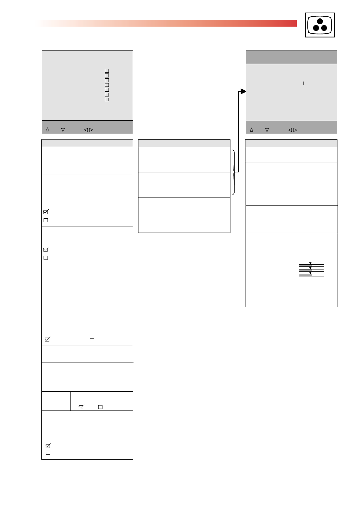
1
ACCESSING SERVICE MODE
2
TEMPORARY EXIT FROM SERVICE MODE
TV Control Panel Access
• Switch the TV into “Standby” mode by pressing the
Standby button on the RCU.
Wait till the TV goes into the standby.
• Press the VOL- button and then the PR- button on the TV
keyboard.
Hold them down for more than 8 seconds.
• After the normal switch on time, when the 8 seconds have
elapsed, the main service menu appears on the screen.
3
EXITING FROM SERVICE MODE
Note :
In service mode :
- Clear any wake-up/sleep/memo/EPG timers
- First installation Mode is overridden.
- Zoom and format are set to standard scanning
- Front Panel lock mode has to be cancelled.
- Pin 8 of the scart plug has to be ignored.
- AV- Link WSS detection and letterbox detection has to be
disabled (autoformat).
- EPG and TELETEXT have to be disabled.
- All passwords have to disabled.
- Press Exit on the Remote control.
- Everyday use menu can be accessed via Menu button.
- Field Service Menu can be re-entrered via Blue button.
- Go to the point QUIT in the Field service
Mode main menu.
Remote Control
on/off key or Stand-by
- Stand-by function or
“off” with on/off key.
- TV mode.
Values or adjustments are no stored before exiting from service
mode will not be written into the NVM
UP
DOWN SELECT
QUIT
Soft-Ver. IFC228_X100
Config W-----V--P-
000046:37
Serial-No.
DVD Soft-ver. 3.12 Serial-No.
Tube
CHASSIS SETUP
FEATURE SETUP
VIDEO
EVENT HISTORY
SOUND
MISCELLANEOUS
- Press “>” button
I - ENTER/EXIT SERVICE MODE
1
UP
DOWN SELECT
QUIT
Soft-Ver. IFC228_X100
Config W-----V--P-
000046:37
Serial-No.
DVD Soft-ver. 3.12 Serial-No.
Tube
CHASSIS SETUP
FEATURE SETUP
VIDEO
EVENT HISTORY
SOUND
MISCELLANEOUS
➠
UP
DOWN SELECT
QUIT
Soft-Ver. IFC228_X100
Config W-----V--P-
000046:37
Serial-No.
DVD Soft-ver. 3.12 Serial-No.
Tube
CHASSIS SETUP
FEATURE SETUP
VIDEO
EVENT HISTORY
SOUND
MISCELLANEOUS
➠
REMOTE CONTROL
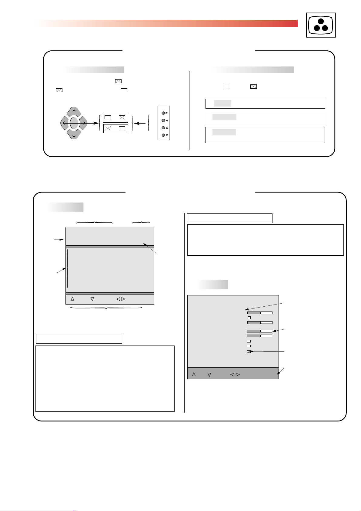
II - NAVIGATION INSIDE THE SERVICE MODE
Naviagation up
Naviagation down
- Select option
- “Change“ value
VALUE
VALUE
>
<
Changing page
- When the highlight is on the first line of a menu a press on the
key display the previous page.
- When the highlight is on the bottom line of a menu a press on the
key display the next page.
« ∆ »
Display
➠
+ >
NVM value
4
DISPLAYING THE VALUE OF THE SETTING
Display
➠
-
<
NVM value
Hexadecimal value
Set value
: NVM value
><
00 to FF
2
TV CONTROL PANEL
UP
DOWN SELECT
QUIT
Soft-Ver. IFC228_X100
Config W-----V--P-
000046:37
Serial-No.
DVD Soft-ver. 3.12 Serial-No.
Tube
CHASSIS SETUP
FEATURE SETUP
VIDEO
EVENT HISTORY
SOUND
MISCELLANEOUS
➠
Navigation up
UP
DOWN SELECT
QUIT
Soft-Ver. IFC228_X100
Config W-----V--P-
000046:37
Serial-No.
DVD Soft-ver. 3.12 Serial-No.
Tube
CHASSIS SETUP
FEATURE SETUP
VIDEO
EVENT HISTORY
SOUND
MISCELLANEOUS
➠
Navigation down
- Select option
- “Change” value
VALUE
VALUE
Vol.
+
-
Vol.
prog.
vol.
3
MENUS WITH MULTIPLE PAGES
« ∆ »
SERVICE MODE
V - Position
+ 7C
Page 7
IFC228 PLASMA
First issue 10 / 04 7
III - LITE-MENU FOR FIELD SERVICE MODE
1
MAIN MENU
Soft-Ver. ITC22_P110-0 000002:48
Config. W4-----P- Serial-No. AR9211092
UP
DOWN SELECT
QUIT
TUBE
CHASSIS SETUP
FEATURE SETUP
GEOMETRY
VIDEO
EVENT HISTORY
SOUND
MISCELLANEOUS
Software Version Counter
Receiver
composition
Serial Number
Alignment
Navigation inside the Service Mode
TV CONFIGURATION
Character 1 : Tube type : “A”= 4:3 , “W” =16:9
Character 2 : Teletext external memory detected: “T”
Character 3 : Ambiant Sensor : “S”= detected, “-” = not
Character 4 : Chassis variant : “N”=Nicam, “V” =Virtual Dolby,
“D”=Dolby digital
Character 5 : Subwoofer: “W” = detected, “-” = not
Character 6 : Guide module : “G” = detected, “-” = not
Character 7 : Flash memory : “F” = detected, “-” = not
Character 8 : Second Tuner (PIP) : “P” = detected, “-” = not
Character 9 : Comb filter : “C” = detected, “-” = not
TIME COUNTER
The counter indicates the TV’s number of service hours.
It counts from to 0 to 65535 hours. The display is hexadecimal.
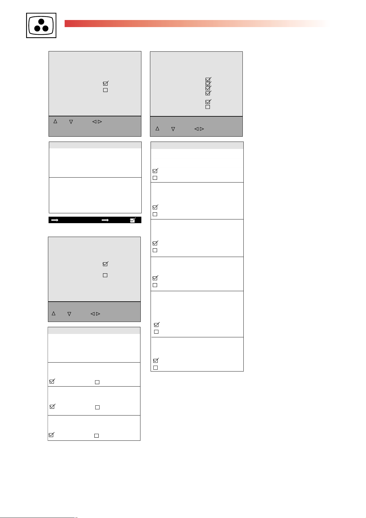
2
SUBMENU
VIDEO PAL BG
UP
DOWN SELECT/CHANGE
80
80
80
80
Scaling Contrast
Contrast max
Text Contrast
Full White 4/3
Drive Level
Defaults
Store
Restore
Navigation inside the Service Mode
Hexadecimal value
Bargraph
Enable a function
Config. W5Z.....V
SERIAL-N° A15...
Character 1 : Factory, A= Angers, B= Tarancon, Z= Zyrardow
Character 2 : Year: G= 1996, H= 1997 etc. (International code UTEC90511)
Character 3 : Month, from 1= January to 9=September...C=December.
Character 4-9 : Serial N° in the month (from 000000 to 999999)
Character 10-18 : Factory reserved
Default
➠
All the default values of a page in use
are stored in RAM.
Restore
➠
Copies all values from NVM into RAM
Store
➠
Copies RAM values into NVM
6
STORING VALUES IN MEMORY
After setting, the values are stored in NVM.
The box becomes
During alignment, values are temporarily stored in RAM.
II - NAVIGATION INSIDE THE SERVICE MODE
➠
To enable a function check (tick) the box.
: Implemented function : No implemented function
5
TOGGLE FUNCTIONS
➠
prog.
vol.
Page 8
IFC228 PLASMA
8 First issue 10 /04
TUBE
FEATURE SETUP
Return
Tube type 16X9
Store
Restore
UP
DOWN SELECT/CHANGE
TUBE
Return
Closes the sub-menu and returns to the
"Main Service Menu"
Press </>: remote control; Vol. +/- : TV keyb.
Tube type
After replacing the NVM, the right panel
configuration for the TV must be entered.
The tube type can be 16x9 or 4x3 panel size.
The new values will be stored into NVM only
when the Store feature is selected.
After setting Store
CHASSIS SETUP
Return
Subwoofer
Top Light
Return
Curtains Effect
Opt.Still Pict.
Auto Film Mode
Demo Mode
Welcome Screen
Program Info
UP
DOWN SELECT/CHANGE
FEATURE SETUP
Curtains Effect*
Enables the "Curtains Effect" function in the
user preferences menus.
Curtains Effect function active.
Curtains Effect function disactivated
Optimised Still Picture*
Enables the "Photo Mode" function in the
user "Picture/Advanced use" menus .
Opt. Still picture active.
Opt. Still picture disactivated
Auto film Mode*
Enables the "Film mode" function in the
user "Picture/Advanced use" menus .
Auto film active.
Auto film disactivated
Demo Mode*
Enables the "Demo" key on the RCU.
Demo Mode active.
Demo Mode disactivated
UP
DOWN SELECT/CHANGE
CHASSIS SETUP
Return
Closes the sub-menu and returns to the
"Main Service Menu"
Press </>: remote control; Vol. +/- : TV keyb.
Subwoofer
Enable the subwoofer on equiped set.
Subwoofer enable Subwoofer disable
DVI
Enable the DVI input on equiped set.
DVI input enable
Toplight
DVI input disable
Enable the "Toplight" function on equiped set.
Toplight enable
Toplight disable
Welcome Screen*
Determines whether or not a Welcome Screen
is shown during the Installation Mode.
When this checkbox is unchecked the
"Contacts" user Menu will be disabled.
Welcome Screen enable
Welcome Screen disable
Program Info*
Enables "Program Info" in the
"Overview" menu of user functions.
Program Info enable.
Program Info disable.
* Changes are saved directly into NVM
Page 9

IFC228 PLASMA
First issue 10 / 04 9
The TV set should be warmed up for 60 minutes before the alignments
VIDEO SECAM L
Return
Cutoff R
Cutoff G
Cutoff B
G2 Alignment
Scaling Colour
Scaling Brightness
Whitepoint R
Whitepoint G
UP
DOWN SELECT/CHANGE
70
70
70
7C
8E
74
6C
VIDEO SECAM
Return
Closes the sub-menu and returns to the
"Main Service Menu"
Press </>: remote control; Vol. +/- : TV keyb.
Cutoff R*
Cutoff G*
Cutoff B*
+
= standard
+
Grey test pattern 15nit luminance level.
PAL, SECAM, RGB, RGB_AUX, COMP1H,
COMP2H, VIDEO DVI.
Measure the Color coordinates near the center
of the screen.
Adjust Cutoff R, Cutoff G
(and perhaps Cutoff B)
to the following coordinates :
Plasma Panel
0.255
x
y
0.270
Scaling Colour*
= standard
+
PAL, SECAM, RGB, COMP1H, COMP2H,
RGB_AUX, VIDEO DVI
75% Colour bar test pattern
Blue output
Videoprocesseur
Main Board index 0 (pin 10/14 BV201)
index d (pin 6/8 BV201)
Main
Board
Scalling
Brightness
Factory adjusted
=
VIDEO SECAM L
Scaling Contrast
F8
Contrast max
Text Contrast
Full White 4/3
Drive Level
Defaults
Store
F4
50
80
Restore
UP DOWN SELECT/CHANGE
VIDEO SECAM
Peak White ( Scalling Contrast)**
++
Peak white test pattern : white centered pad
(100 IRE, 2% of the picture surface) on dark background in the following standards :
PAL, SECAM, RGB, RGB_AUX, Video DVI,
COMP1H, COMP2H, PC_RGB, PC DVI.
Adjust with
level to the level defined in the table below :
= standard
B=71
Scalling Contrast the light output
Colourimeter
Tube Type
Fujitsu H 37"
Fujitsu H 42"
[Nits] Limit
300
+20/-15%
300
+20/-15%
Contrast max
Set (temporary) the user contrast bargraph to max.
When "Contrast max." is deselected the user
contrast bargraph set back to the previous value.
Contrast max. enable
Contrast max. disable
Text
Contrast
+
+
= standard
Adjust Text contrast for V=0.5V at pin10/14
(Main Board index0) or pin 6/8 (Main board
indexd) :
Text Contrast 9C
V=0.5V
Measure the optical luminance output level
Y (nit) of the white pad :
Adjust with Text contrast the output level :
60% V peak white.
Full White 4/3 (16/9)
Drive Level
After setting Store (+)
Whitepoint R*
+
=
Grey scale test pattern
white =50%
PAL, SECAM, RGB,RGB_AUX
COMP1H, COMP2H, VIDEO DVI,
PC RGB, PC DVI
standard
grey
Whitepoint G*
Colorimeter : Adjust to the Color
coordinates at the center:
Plasma Panel
0.255
x
y
0.270
Note :
* Adjust separate for PAL RF/SECAM RF and
RGB_AUX
** After PEAK white adjustment control white points
setting.
Repeat the adjustments if necessary.
Factory adjusted
Page 10
IFC228 PLASMA
10 First issue 10 /04
EVENT HISTORY
Return
Clear Event Codes
Code Count Time Stamp
15 005 000000:06
00 000 000000:00
00 000 000000:00
00 000 000000:00
000000:00
SOUND
Return
Effect Strength (MED)
Effect Strength (HIGH)
Low Pass Frequency
High Pass Frequency
Sub-woofer Corner Frequency 80
Defaults
Store
Restore
UP
DOWN SELECT/CHANGE
80
9A
80
56
EVENT HISTORY
Return
Closes the sub-menu and returns to the
"Main Service Menu"
Press </>: remote control; Vol. +/- : TV keyb.
Clear Event Codes
To clear all event codes stored in the
NVM. Action:
Long press (> 2.5sec.).
Press </>/OK: remote control.
CODE
1- The last five error codes are stored and
displayed with a time stamp from the run time
counter
2- If an error occurs that is already in the list
the time stamp is updated .
3- The errors are displayed with the most recent
error on top of the list. The others follow with
descending time stamps.
Displaying Error Codes with LED:
1- In addition to storing an error code it must
also be displayed with the TV's Standby LED.
Only the last error that occured is displayed.
2- Decimal error codes from 11 to 99
(with second digit not being 0) are signalled.
3- The error code is displayed as two separate
digits separated by a suitable pause, this is
repeated until the either the TV fixes the fault
or the TV is repaired.
For example Error-code : 23 will be displayed
thus :
2 flashes and a short pause
3 flashes and a long pause
.........
List of Error Codes : see table
SOUND SETTINGS
Return
Closes the sub-menu and returns to the
"Main Service Menu"
Press </>: remote control; Vol. +/- : TV keyb.
Adjust "Sound settings" registers according
to the TV environments (refer to the below table)
when the NVM memory has been replaced.
On entering this menu the sound mode will be
switched to normal and the "Dynamic Bass"
feature activated.
Effect Strength (MED) 3F
Effect Strength (HIGH) 43
Low Pass Frequency 08
High Pass Frequency 04
Sub-woofer corner Freq. 14
After setting Store (+) After setting Store (+) After setting Store (+)
List of Error Codes
11 I2C bus_1 data line held low
12 I2C Bus_1 clock line held low
13/95 I2C Bus_2 data line held low
14/95 I2C Bus 2 clock line held low
15 I2C Bus_3 data line held low
16 I2C Bus 3 clock line held low
17 I2C Bus_4 data line held low
18 I2C Bus 4 clock line held low
19 Invalid chassis detected
25 Main tuner doesn't answer anymore
26 Secondary tuner (PIP) doesn't answer anymore
27 IX300 (TEA6415C) doesn't answer anymore
28 IV300 (TA1360) doesn't answer anymore
29 9V IV300 Power down detection
41 IA001 (MSP) doesn't answer anymore
42 The reset bit IA001 (MSP) is active
45 Wrong MSP is fitted
48 PIP FI doesn't answere anymore
49 5V PIP FI Power down detection
54 NVM IR005 (M24C64) doesn't answer anymore
55 IR006 (PCF8574) doesn't answer anymore
58 Code validation failed
59 Wrong IR001 is fitted
61 5VON not present
63 Unexpected level on NMI line found
69 H/V Synch. for OSD missing
72 IX400 (CXA2151) doesn't answer anymore
93 IR001 : Err_I2C Bus_1 and Err_I2C Bus_2 (Bus drivers)
94 IR001 : Err_I2C Bus_3 and Err_I2C Bus_4 (Bus drivers)
95 IR001 : Err_I2C. Port driver can not be installed
96 IR001 : ADC driver can not be installed
97 IR001 : AV-link driver can not be installed
98 SDRAM (IR110) Problematic SDRAM timing
99 IR001 Watchdog hit
Page 11
IFC228 PLASMA
First issue 10 / 04 11
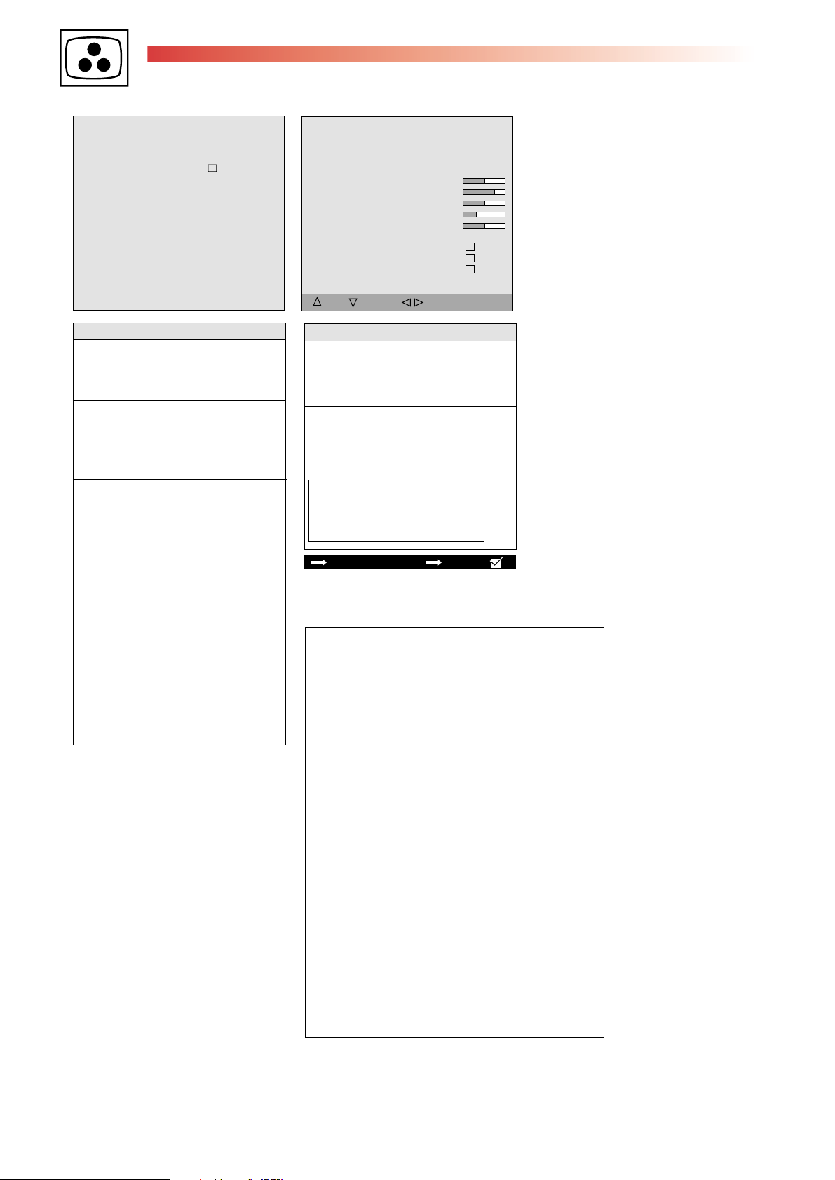
MISCELLANEOUS
Return
Clear Progs
Default Presets
Bus Quiet
Development Support
Restore Factory Settings
FFI-Bit
Switch 2nd Tuner to Main
Scaler PC
Scaler DVI
ADC Calibration
UP
DOWN SELECT/CHANGE
Soft-Ver V1.00
Return
Factory reset ....
Internal ADC Calibration ....
Test Pattern ....
Video settings ....
UP
DOWN SELECT/CHANGE
MISCELLANEOUS
Return
Closes the sub-menu and returns to the
"Main Service Menu"
Press </>: remote control; Vol. +/- : TV keyb.
Clear Progs.
Clears all programms stored in memory and
resets all Picture and Sound settings to the factory
defaults. The AUTO INSTALL (out of factory)
mode can be initialised by a long press (>2s.)
of the selection button.
Clear Progs enable
Clear Progs disable
Default Presets
Sets the default (ROM) value for all the factory
sound and picture presets.
Default Presets enable
Default Presets disable
Bus Quiet
In "Bus Quiet", the NVM can be read, modified
and reprogrammed by means of a NVM
Programmer.
To access "Bus Quiet" : Long press ">".
The TV should remain in "Bus Quiet" mode
until either Exit, Left, Right, Up,Down or
Standby keys on the RCU or local keyboard
are pressed; at which point the TV should
carry out a warmstart in order to prevent
differences between the NVM and RAM
contents.
After returning from Bus Quiet, the software
checks the NVM content.
If it is not valid, the software perform a new
default writing of the NVM content.
Bus quiet enable Bus quiet disable
Developpement Support
Factory adjusted
Restore Factory Settings
Restores the correct "out of box" condition.
Some settings will be restored from a
reserved backup NVM area and others will be
defaulted from the ROM.
FFI - Bit
Fast Filter (IF / PLL)
MISCELLANEOUS Soft-Ver V1.00*
Scaler PC
Selects the PC field service menu with VGA
as input source: TV in AV4, PC AV source.
The signal must be connected to VGA port
Scaler DVI
Selects the PC field service menu with DVI as
input source: TV in AV5, DVI AV source.
The signal must be connected to DVI port.
ADC calibration (Ext. ADC)
Start the automatic ADC alignment routine.
Insert a grey test pattern
Select ADC calibration and press left or right
button. Alignment will be carried out automatically.
When complete the word "done" will be displayed.
Menu service can be re- entred via Blue button.
Factory reset
Reset to factory values.
Internal ADC Calibration
Triggers the scaler internal ADC alignment routine.
Grey scale test pattern input :
- to VGA port for Scaller PC
- to DVI port for Scaller DVI
When complete the word "Done" is displayed.
Moving the cursor away will automatically
erase the word and ready the system for
another calbration is required.
Test pattern
Displays the internal test pattern.
The ">" button toggles through the colour :
White, Black, Red, Green and Blue.
A
fter the last pattern the main menu is displayed
Video settings
Displays the video submenu below.
Return
Red
Green
Blue
Peak white adjustment
Depending on user selection, the changes will
either modify PC VGA or PC DVI RGB
settings.
Note :
If not test pattern connected and when the item
return is selected the message "No signal PC"
is displayed.
To return at the Service menu it's necessay
to press a numeric button ant then the
Blue button
191
190
194
Asia
Switch 2nd Tuner to Main
The current signal on the second tuner is
switched to the main screen and the AV1
output.
Changing program/channel on main tuner, the
main screen stays on the second tuner.
Europe
Switch 2nd Tuner to Main enable
Switch 2nd Tuner to Main disable
Page 12

13
IFC228 PLASMA
First issue 10 / 04 12
SCHEMATIC DIAGRAMS
MAIN
AV_IN
MAIN
VIDEO SW
L_IN_AV1
R_IN_AV1
L_IN_AV2
R_IN_AV2
L_IN_AV3
R_IN_AV3
R_IN_FCB
L_IN_FCB
R_IN_COMP1
L_IN_COMP1
RA200
GND
220P0
CA200
CA202
220P0
CA212
220P0
CA240
220P0
CA242
220P0
220P0
CA210
CA220
220P0
CA222
220P0
4K7
RA202
4K7
RA210
RA212
RA220
RA222
RA230
RA232
4K7
RA240
RA242
4K7
4K7
4K7
4K7
4K7
4K7
4K7
GND
GND
GND
GND
GND
RA241
47K
RA243
47K
CA201
220P0
CA203
220P0
220P0
CA211
CA213
220P0
CA221
220P0
CA223
220P0
GND
GND
GND
RA231
47K0
RA233
47K0
GND
GND
GND
GND
GND
RA201
47K0
RA203
47K0
RA211
47K0
RA213
47K0
GND
GNDGND
CA241
330P0
CA243
330P0
RA221
47K0
RA223
47K0
GND
220P0
GNDGND
GND
LA200
300
LA201
300
LA210
300
LA211
300
LA220
300
LA221
300
LA230
300
LA231
300 CA233
LA240
300
LA241
300
GND
GND
GND
GND
GND
GND
GND
220P0
CA230
CA232
220P0
GND
220P0
CA231
GND
RA225
0
RA224
0
IFC228 MAIN E
2135261B
0B/S
AUDIO 1
18may04
AV_IN
R_OUT_AV1
L_OUT_AV1
R_OUT_AV2
L_OUT_AV2
Red
Whi
Red
Whi
BA200
AV1_L_IN
AUDIO 2
AV1_R_IN
AV2_L_IN
AV2_R_IN
FCB/AV3_R_IN
FCB/AV3_L_IN
COMP1_R_IN
COMP1_L_IN
RA250
LA250
CA250
1N0
LA251
CA253
1N0
LA260
CA260
1N0
CA263
1N0
1
2
3
4
5
6
GND
7
8
LA282
300
220R0
GND
RA252
220R0
GND GND
RA260
220R0
RA262
GND
220R0LA261
GND
LA271
300
CA270
220P0
LA272
300
LA281
300
GND GND GND
220P0
CA272
GND
CA280
220P0
GND
CA282
220P0
GND
GND
GND
RA270
4K7
RA272
4K7
RA280
4K7
RA282
4K7
CA251
470P0
CA254
470P0
470P0
CA261
CA264
470P0
GND
GND
GND
GND
GND
GND
RA271
47K
RA273
47K
RA281
47K
RA283
47K
RA251
47K0
RA253
47K0
RA261
47K0
RA263
47K0
CA252
22U0
CA255
CA265
22U0
GND
GND
22U0
CA262
22U0
CA271
330P0
CA273
330P0
CA281
330P0
CA283
330P0
AV1_R_OUT
AV1_L_OUT
AV2_R_OUT
AV2_L_OUT
DVI_R_IN
DVI_L_IN
VGA_L_IN
VGA_R_IN
AUDIO 2
AUDIO 2
GNDGNDGND
Page 13

MAIN (VIDEO PROCESSOR OPTION)
IFC228 PLASMA
15 First issue 10 / 04
14
MAIN
VP/ADC
3V3_UC
1V8_UC
U_BB
Y_GG
V_RR
LY001
CY001
10UF
16V
RY040
0R
RY041
0R
RY042
0R
10UH
VSP
0
CY008
100UF
16V
DAC_BOUT
DAC_GOUT
DAC_ROUT
RY009
47R
656IO_0
656IO_1
656IO_2
656IO_3
656IO_4
656IO_5
656IO_6
656IO_7
CY002
10UF
16V
10UH
LY002
GND
CLKOUT
656VIO
656HIO
1V8_CORE
LY003
10UH
LY004
10UH
1V8_DAC
RY015
8R2
RY014
180R
CY003
10UF
16V
CY009
100UF
GND
RY010
CY024
4
CY035
16V
GND
47R
100N
1
4
1
1
4
100N
CY005
10UF
16V
RY043
33R
RY044
33R
RY045
33R
CY038
100N
CY004
RY011
47R
8
8
5
8
5
CY034
100N
10UF
16V
CY039
33P
QY001
RY012
D1DATA0
D1DATA1
D1DATA2
5
DIDATA3
D1DATA4
D1DATA5
D1DATA6
D1DATA7
D1_CLK
D1FID
D1_VSYNC
D1_HSYNC
RY029
CY026
100N
1M
10K
CY037
100N
CY033
100N
CY025
100N
3V3_DAC
CY031
100N
13.5MH
CY030
100N
CY027
100N
CY007
10UF
16V
CY040
RY030
10K
CY036
100N
CY032
100N
33P
Z
RY031
10K
GND
CY029
100N
10UF
16V
CY028
CY006
RY013
1M
100N
3V3_IO
RY027
4K7
RY028
1V8_PLL
0R
XTAL_IN
XTAL_OUT
RY001
33R
876
1
5
4
VID_OUT7
OE
155
156
157
158
159
160
161
162
163
164
165
166
167
168
169
170
171
172
173
174
175
176
177
178
179
180
181
182
183
184
185
186
187
188
189
190
191
192
193
194
195
196
197
198
199
200
201
202
203
204
205
206
207
208
2345678910
1
RY002
33R
876
1
VID_OUT4
VID_OUT5
VID_OUT6
152
153
154
5
4
VID_OUT1
VID_OUT2
VID_OUT3
149
150
151
SINGLE NET
(16/20/24bit output)
VHS_CSYNC
VVS
RY003
33R
876
1
VID_OUT0
146
147
148
5
4
VID_OUT12
VID_OUT13
VID_OUT14
VID_OUT15
142
143
144
145
RY004
33R
876
1
VID_OUT10
VID_OUT11
138
139
140
141
VID_OUT9
137
5
4
VID_OUT22
VID_OUT23
VID_OUT8
134
135
136
RY005
33R
876
1
VID_OUT18
VID_OUT19
VID_OUT20
VID_OUT21
130
131
132
133
129
128
5
4
CLK_OUT
VID_OUT16
VID_OUT17
125
126
127
124
RY006
33R
876
1
CTLOUT4
123
122
120
121
RY007
5
4
CTLOUT0
CTLOUT1
118
119
117
33R
116
876
1
115
114
113
5
4
112
111
IY001
FLI 2300
FAROUJA
121314151617181920212223242528293031323334353637383940414243444546474849505152
11
27
26
110
109
108
107
106
105
DATA0
DATA1
RY050
0R
RY051
0R
DATA2
104
103
102
101
100
99
98
97
96
95
94
93
92
91
90
89
88
87
86
85
84
83
82
81
80
79
78
77
76
75
74
73
72
71
70
69
68
67
66
65
64
63
62
61
60
59
58
57
56
55
54
53
HDFL
VDFL
SDRAM_CLKIN
SDRAM_CLK
WEN
ADDR0
ADDR1
ADDR2
ADDR3
ADDR4
ADDR5
ADDR6
ADDR7
ADDR8
ADDR9
ADDR10
DATA31
DATA30
DATA29
DATA28
DATA27
DATA26
DATA25
DATA24
DATA23
DATA22
DATA21
DATA20
DATA19
DATA18
DATA17
DATA16
DATA15
DATA14
DATA13
DATA12
DATA11
DATA10
DATA9
DATA8
DATA7
DATA6
DATA5
DATA4
DATA3
RY024
10K
DQM
CSN
BA0
BA1
CASN
RASN
VP/ADC
RY025
100R
DATA23
DATA22
DATA21
DATA20
DATA19
DATA18
DATA17
DATA16
DQM
ADDR2
ADDR1
ADDR0
ADDR10
BA1
BA0
CSN
RASN
CASN
WEN
DQM
DATA7
DATA5
DATA3
DATA1
DATA0
LY005
10UH
CY010
100UF
16V
IY002
MT48LC2M32B1
43
VDD4
42
DQ23
41
VDDQ4
40
DQ22
39
DQ21
38
VSSQ4
37
DQ20
36
DQ19
35
VDDQ3
34
DQ18
33
DQ17
32
VSSQ3
31
DQ16
30
NC3
29
VDD3
28
DQM2
27
A2
26
A1
25
A0
24
A10
23
BA1
22
BA0
21
NC2
20
CS
19
RAS
18
CAS
17
WE
16
DQM0
15
VDD2
14
NC1
13
DQ7
12
VSSQ2
11
DQ6
10
DQ5
9
VDDQ2
8
DQ4
7
DQ3
6
VSSQ1
5
DQ2
4
DQ1
3
VDDQ1
2
DQ0
1
VDD1
100N
CY020
VSS1
DQ24
VSSQ5
DQ25
DQ26
VDDQ5
DQ27
DQ28
VSSQ6
DQ29
DQ30
VDDQ6
DQ31
VSS2
DQM3
DQM1
VSS3
VDDQ7
DQ10
VSSQ7
DQ11
DQ12
VDDQ8
DQ13
DQ14
VSSQ8
DQ15
VSS4
3V3_IO
NC4
A3
A4
A5
A6
A7
A8
A9
CKE
CLK
NC5
NC6
NC7
DQ8
DQ9
44
45
46
47
48
49
50
51
52
53
54
55
56
57
58
59
60
61
62
63
64
65
66
67
68
69
70
71
72
73
74
75
76
77
78
79
80
81
82
83
84
85
86
CY021
100N
100N
CY022
DATA24
DATA25
DATA26
DATA27
DATA28
DATA29
DATA30
DATA31
DQM
ADDR3
ADDR4
ADDR5
ADDR6
ADDR7
ADDR8
ADDR9
CKE
DATA8
DATA9
DATA10
DATA11
DATA12
DATA13
DATA14
DATA15
470R
RY035
CY023
100N
SDRAM_
CLKIN
3V3_A
RY034
10K
RY033
10K
IFC228 MAIN EU
RY032
10K
RY039
10K
LY008
10UH
CY012
100UF
16V
CY015
100N
CY014
100N
CY016
100N
CY011
3V3
100UF
16V
GND
GND
RY022
RY023
10K
IIC_CL_2
IIC_DA_2
(OPTION)FLI 2300 VIDEO PROCESSOR
SOFT_RESET
RY038
470R
RY036
470R
RY037
470R
GENCAM 1
RY046
0R
RY047
0R
RY021
5V_STBY
10K
RY020
0R
GND
0R
1
2
3
4
BY001
CY018
CY019
100N
100N
LY006
10UH
CY017
100N
16V
10UH
LY007
CY013
10UF
Page 14

IFC228 PLASMA
First issue 10 / 04 16
17
MAIN (DIGITAL VISUAL INTERFACE)
MAIN
WC
(to BT501)
RT613
BT600
+3.3V_DVI
+5V_DVI
DT604
MMSZ6V8T1
RT612
12K
100R
RT614
0R
GND
1
RX2-
2
RX2+
3
4
GND
5
6
DVI_SCL
7
DVI_SDA
8
9
10
11
12
13
14
15
16
17
18
19
20
21
22
23
24
RX1-
RX1+
GND
+5V
GND
HTPLUG
RX0-
RX0+
GND
TXC+
TXC-
GND
LT601
330NH
RT601
100R
CT602
100NF
0
RT602
100R
TT601
PMBF170
TT602
PMBF170
GND
GND
D
RT603
8
7
6
5
MMSZ6V8T1
DT602
MMSZ6V8T1
DT603
D
S
G
4K7
1
2
3
4
M24CO2-WMN6
8
VCC
7
WC
6
SCL
5
SDA
GND
S
G
IT620
MODE /
100NF
CT608
RT606
100R
RT605
100R
PRE
PB0
PB1
VSS
IT630
CT691
220UF
10V220N
LD1117DT33
OUT
3K3
RT621
LT643
330NH
CT653
10UF
16V
GND
RT059
0R
RT058
0R
RT057
GND
GND
DVI_DETECT
LT642
330NH
CT649
100NF
CT648
100PF
0R
DVI_B
DVI_G
DVI_R
DVI_VSYNC
DVI_HSYNC
IN
CT693
220N
GND
DVI_B
DVI_G
DVI_R
VIDEO SW
6V
GENCAM 1
CT650
10UF
16V
VGA
+3.3V_DVI
CT655
100NF
CT632
22PF
680NH
LT621
RT636
1M
RT628
75R
LT641
330NH
LT622
680NH
RT056
RT055
RT635
100K
0R
0R
GND
CT633
22PF
CT634
22PF
GND
RT604
33K
330NH
LT644
CT656
10UF
16V
680NH
LT623
CT642
47UF
16V
20506520
CT635
22PF
CT692
GND
CT652
100NF
CT651
100PF
CT636
22PF
GND
DVI_VSYNC
DVI_HSYNC
VGA
TT632
BC856B
RT634
470R
CT644
10UF
16V
CT654
100PF
RT627
75R
470R
RT041
RT622
470R
CT631
22PF
RT626
75R
DIGITAL VISUAL INTERFACE (DVI)
IFC228 MAIN EU
CT646
100NF
37
DACVCC
DGND_1
DVCC_1
100PF
CT626
RT609
33K
RT631
300R
36
SDAM
HSYNC
RT632
300R
35
DACGND
VSYNC
CT647
10UF
16V
GND
34
SCLM
DACGNDB
DACVCCB
COMP
RSET
DACGNDG
DACVCCG
DACGNDR
DACVCCR
VCC_2
GND_2
PD_DAC
TT631
IOB
IOG
IOR
CT621
100PF
BC846B
RT637
143R
33
32
31
30
29
28
27
26
25
24
23
22
21
300R
RT633
CT643
10NF
LT611
330NH
LT612
330NH
100NF
CT604
1
2
3
4
GND
GND
IT607
NSAD500H
GND
IT608
NSAD500H
2
4
RT650
10R
1
2
3
4
1
3
RT651
16V
CT615
10UF
RT611
412R0
10R
CT614
100PF
100PF
CT613
GND
100NCT612
CT61110UF
LT614
330NH
CT625
100PF
7
5
100PF
CT620
8
6
CT616
100NF
CT624
7
5
CT607
100NF
8
6
CT617
100PF
100NF
CT623
47
48
49
50
51
52
1
2
3
4
5
6
7
GND
CT619
100NF
10UF 16V
AGND_3
RX2+
RX2-
AGND_2
RX1+
RX1-
AVCC_1
RX0+
RX0-
AGND_1
RXC+
RXC-
AVCC_2
CT618
10UF
LT613
330NH
CT645
100PF
39
40
41
42
43
44
45
46
VCC_3
GND_3
DE
DGND_2
ODCK
SCDT
DVCC_2
RESETN
IT600
SII907B
SCLS
EXT_RES
PVCC_1PDPGND_1
8
9
1011121314151617181920
33K
RT610
GND_1
VCC_1
SDAS
CT622
100PF
38
RESERVED
Page 15

MAIN (FRONT END)
IFC228 PLASMA
19 First issue 10 / 04
18
(M)
480_ON(US)
3D_FRAME(US)
(M)
IR
3V3_STBY
to Wired-IR
FRONT-END
5V_STBY
IFC228 MAIN EU
RR026
150R
IR
POWER
RR030
330R
TOPLIGHT
JR010
0R
JR801
0R
JR800
0R
GND
1
2
3
4
5
6
RR903
100R
RR902
100R
RR901
100R
RR900
100R
IIC_DA_2
IIC_CL_4
IIC_DA_4
IIC_CL_2
GM_INTERRUPT
GM_BUSY
1
2
3
1
2
3
4
1
2
3
4
5
RR402
100R
RR401
56R
RR400
100R
IR
220R
RR362
RR360
220R
39P
CR360
470R
RR361
1K
RR051
RR365
1K
CR362
39P
2K2
RR366
BC846B
TR365
CR365
100P
RR369
10K
100P
CR370
4K7
RR370
BC856B
TR370
KEYBOARD
CR057
39P
47N
CR009
1K5
RR005
1%
CR006
10N
RR117
1K5
JTIN
CR150
47N
CR049
39P
CR197
39P
CR196
39P
39P
CR195
IR_OUT
CR194
39P
UART_IN
CR193
39P
CR155
39P
CR154
39P
JTSEL
JTCLK
JTOUT
0R
JR140
RR203
4K7
47N
CR185
39P
CR058
39P
CR162
5V_STBY
IR
39P
CR161
CR164
39P
39P
CR163
JR053 0R
0RJR052
JR051 0R
0RJR050
JR081
0R
JR080 0R
CR008
47N
POWER_SWITCH
CR007
10N
47N
CR065
JR017
0R
TR015
BC856B
RR015
1K5
10K
RR009
453R
RR017
0R
JR025
560P
CR024
100R
RR024
RR028
2K2
RR023
1K
TR023
BC846B
RESTART_LED
1K
RR022
100R
RR021
BC856B
TR024
12345
6
123456789
10
11
1
2
3
4
5
6
7
8
9
10
1
2
100R
RR029
100R
RR027
RR025
56R
3V3_STBY
WE_ROM#
GND
DVI_DETECT
ZMM6.8
DR362DR360
ZMM6.8
SAFETY_ENABLE
IR_UC
5V_STBY
SYNC_ENABLE
FB_OSD
B_OSD
G_OSD
R_OSD
SAFETY_ENABLE
3V3_STBY
DVD_KEY
SAFETY_INT
RESET#
VDFL
HDFL
RESET_DMU#
DVI_DETECT (US)
LED_TOPLIGHT
RESTART_LED
TUBE_DETECTION
IIC_DA_4
IIC_CL_4
IRDA_OUT
UART_OUT
AQR_ON
RESET#
EXT_ON#
DC_DC_ON#
ECO_STANDBY#
AUDIO_STBY_MUTE#
RESET_AUDIO#
MASTER_MUTE#
CVBS_TXT_S
LED#
DEGAUSS
5V_ON_CHECK
IIC_DA_1
IIC_CL_1
1V8_STBY
3V3_STBY
5V_STBY
5V_V
INF_POW_FAIL
PO
AQR_ON
BSVM_BLANK
FW_ADJUST
EFC
PO_TR
G2_ADJUST
VDFL
HDFL
INT_DMU
IIC_DA_2
CVBS_TXT_M
IIC_DA_4
IIC_CL_4
IIC_DA_3
IIC_CL_3
IIC_DA_2
IIC_CL_2
IRDA_IN
5V_STBY
IIC_CL_2
IIC_DA_2
IIC_CL_2
IIC_DA_2
IIC_DA_2
IIC_CL_2
IIC_CL_2
IIC_CL_4
IIC_DA_4
LED
KEYBOARD
DEBUG
JTAG
FE-BOX
KEYBOARD
GENCAM 1
GENCAM 1
VOLTAGE REGULATOR
VIDEO SW TUNER DVI VP/ADC AUDIO 2 COMB
5V_V
BR360*
BR002
BR001
To BK02
To BK01
3V3_STBY
5V_STBY
BR007*
BR006*
BR200*
5V_STBY
3V3_STBY
BR005*
(to 1501)
BV900*
MAIN
*Some models only
Page 16

IFC228 PLASMA
First issue 10 / 04 20
21
MAIN (AUDIO MSP)
AUDIO 1
RA015
470R0
GENCAM
AUDIO 1
TUNER
VOLTAGE
REGULATOR
MAIN
COMP2_R_IN
COMP1_R_IN
VGA_R_IN
RA501
47R0
COMP1_L_IN
COMP2_L_IN
VGA_L_IN
IIC_CL_2
IIC_DA_2
LA002
15U0
RESET_AUDIO# 47R0
RA016
47R0
CA002
47P0
GND
FCB/AV3_L_IN
FCB/AV3_R_IN
AV2_L_IN
AV2_R_IN
AV1_L_IN
AV1_R_IN
AM_AF
SIF
5V_V
9V
8V
GND
RA500
47R0
LA003
15U0
RA018
47R0
CA025
1U0
CA026
1U0
CA027
1U0
CA028
1U0
CA031
1U0
CA032
1U0
CA037
1U0
CA041
220N0
CA500
1U0
CA503
CA505
1U0
GND
GND
JA501
0
JA502
0
1U0
CA504
1U0
RA017
470R0
GND
CA021
47P0
GND
CA022
47P0
GND
CA018
CA001
47P0
CA020
180P0
RA021
1K0
CA029
CA034
GND
1U0
47P0
GND
47P0
LA004
10U0
LA005
10U0
GND
CA030
47P0
CA033
47P0
RA019
1K0
RA020
1K0
GND
RA022
1K0
RA023
1K0
RA024
1K0
CA038
JA500
1N0
CA501
1U0
0
CA017
CA019
180P0
RA014
1K0
100N0
GND
!
RA027
4R7
CA042
220UF
10V
1U0
CA024
4U7
CA023
GND
CA502
1U0
JA503
0
CA521
100N0
GND GND GND GND
RA013
1K0
GND
CA035
100N0
CA036
10U0
LA006
CA043
100N0
GND
GND
0
GND
RA025
1K0
GND
CA520
47UF
RA002
GND
41
42
43
44
45
46
47
48
49
50
51
52
53
54
55
56
57
58
59
60
61
62
63
64
CA039
100P0
28
1
27
SCL
SDA
GND
CAPA
2
!
SC3_OUT_R
SC3_OUT_L
AHVSS1
AHVSS2
AGNDC
NC3
SC4_IN_L
SC4_IN_R
ASG1
SC3_IN_L
SC3_IN_R
ASG2
SC2_IN_L
SC2_IN_R
ASG3
SC1_IN_L
SC1_IN_R
VREFTOP
SC5_IN_L
SC5_IN_R
AVSS1
AVSS
NC4
NC5
RA026
1K0
26
ADDR
VS
LA001
10U0
RA010
4R7
CA010
100N0
CA011
1N0
CA014
10U0
CA013
GND
25
L1 R1
4
CA519
100N0
10U0
24
5
CA040
100P0
CA506
1U0
21
22
23
R2
R3
NC
NC
IA500
TEA6422D
NC
L3
L2
NC
7
638
CA518
47UF
8V
CA009
220N0
GND
10U0
CA012
38
39
40
CAPL_A
AHVSUP
CAPL_M
AVSUP1
AVSUP
ANA_IN1+
656667
CA044
10N0
GND
19
20
R4R5R6
L5
L4
9
1011121314 15
9V
RA012
100R0
RA011
100R0
GND
35
36
37
VREF1
SC1_OUT_L
SC1_OUT_R
ANA_IN-
TESTEN
ANA_IN2+
68
70
69
CA045
47P0
16
17
18
LOUT3
ROUT2
ROUT3
L6
LOUT2
ROUT1
LOUT1
CA522
1U0
1U0
CA517
31
32
33
34
DACM_SL
SC2_OUT_L
SC2_OUT_R
IA001
MSP44XYK
XTAL_IN
XTAL_OUTNCTP
71
QA001
18M432
CA046
3P3
CA047
3P3
GND
GND
CA513
1U0
29
30
DACM_C
DACM_SR
DACM_SUB
SPDIF_OUT
AUD_CL_OUT
7672757374
GND
GND
GND
26
272825
DACM_L
DACM_R
D_CTR_I/O_0
D_CTR_I/O_1
78
77
79
CA048
100U0
JA505
0
JA504
0
GND
VREF2
DACA_R
DACA_L
I2S_DA_IN4
I2S_DA_IN3
RESETQ
I2S_WS3
I2S_CL3
I2S_DA_IN2
DVSS3
DVSS2
DVSS1
DVSUP3
DVSUP2
I2S_DEL_WS
I2S_DEL_CL
I2S_DEL_OUT
I2S_DEL_IN
I2S_DA_IN1
I2S_DA_OUT
I2S_WSS
I2S_CL
I2C_DA
I2C_CL
STANDBYQ
ADR_SEL
80
LA007
0
CA049
1N0
GND
NC2
NC1
GND
CA516
1U0
JA507
CA015
470P0
JA506
CA016
470P0
RA505
100K0
0
GND
0
24
23
22
21
20
19
18
17
16
15
14
13
12
11
10
9
8
7
6
5
4
3
2
1
CA050
100N0
GND
CA003
1N0
GND
GND
CA400
47UF
RA009
CA008
470P0
15K0
RA001
CA507
1N0
100R0
CA401
100N0
RA401
15K0
RA402
RA008
100R0
15K0
LIN_EXT
VIDEO SWITCH
RA602
0
RA601
0
GND
CA007
470P0
GND
RA004
100R0
RA003
100R0
33
GND
34
RESETQ
35
TEST
36
DVSS
37
DVSUP
38
WS
39
CL
40
DA_IN
41
DA_OUT
42
ADR_SEL
43
SDA
44
SCL
GND
CA515
1U0
AV1_R_OUT
AV1_L_OUT
AV2_L_OUT
AV2_R_OUT
GND
GND
32
NC31
NC32
NC1
NC
1
2
GND
CA300
4U7
CA052
1N0
CA304
4U7
CA051
1N0
5V_V
29
30
31
NC28
NC29
NC30
IA400
MAD48XYA
NC2
NC3
NC4
4
3
5
RA502
100K0
28
NC27
NC5
6
27
7
NC26
NC6
GND
RA300
3K9
RA305
3K9
CA306
10U0
26
NC25
NC7
8
25
9
NC24
NC8
CA514
1N0
24
NC23
NC9
10
23
11
GND
CA307
100N0
GND
NC22
NC10
NC21
NC19
NC20
NC18
NC17
NC16
NC15
NC14
NC13
NC12
NC11
DVI_L_IN
DVI_R_IN
RIN_EXT
VIDEO SWITCH
4U7
JA001
CA081
4U7
JA002
CA082
4U7
JA003
RA301
100K0
CA302
10U0
RA306
100K0
CA080
0
0
0
GND
22
21
20
19
18
17
16
15
14
13
12
RA007
100R0
RA006
100R0
RA005
100R0
RA302
18K0
2
3
GND
6
5
GND
RA307
18K0
GND
IFC228 MAIN EU
IFC228 AUDIO MSP°
RA506
3K3
RA507
3K3
RA508
3K3
RA304
10K0
CA303
8
220U0
1
4
IA300
TS482D
CA305
8
220U0
7
4
RA308
10K0
some models°
AUDIO 1
GND
GND
GND
GND
GND
RA303
100R
RA309
100R
GND
GND
CA006
1N0
CA005
1N0
CA004
1N0
IA301
ESDA14V2L
LA300
300R0
GND
LA301
300R0
IA302
ESDA14V2L
BA300
(M)
3
2
1
VIDEO_OUT
SW_DETECT
PG
SUBWOOFER
5V_V
MAIN_LEFT
GND
MAIN_RIGHT
SUB_MUTE
L/R_MUTE
AUDIO_STBY
MASTER_MUTE#
L
R
BA001
14
13
12
11
10
9
8
7
6
5
4
3
2
1
BA001=>BS006(audio
BA300=>BQ02(KDB)
Page 17

MAIN (VIDEO GRAPHIC ADAPTOR)
IFC228 PLASMA
23 First issue 10 / 04
22
MAIN
BT501 =>BX003
B_OUT
1
2
VGA_GND
3
4
VGA_GND
5
R_OUT
6
VGA_GND
7
V_OUT
8
H_OUT
9
WC
10
11
IIC_CL_3
12
IIC_DA_3
13
RX
14
TX
WC
(to IT620)
GND
CT507
1UF
CT508
1UF
CT509
1UF
VGASEL
HDCRIN
RAIN
MRED
HDYIN
GAIN
MGRNG_OUT
VGA_GND
1
2
3
4
5
6
7
8
VGA_HIN
H_OUT
DVI_HSYNC
IIC_CL_3
IIC_DA_3
VGASEL
IT502
FSAV330
1
2
3
4
5
6
7
7
100N
CT529
GENCAM 1
16
15
OE_
14
13
12
11
10
B3
9
Y3
IT503
74HC4053
BY
BX
CY
C-COM
CX
INH
VE E
GND C
B-COM
A-COM
HDCBIN
BAIN
MBLU
VCC
AY
AX
A
B
100N
CT502
16
15
14
13
12
11
10
9
CT544
10UF
VGA_GND
5V_V
V_OUT
VGA_VIN
DVI_VSYNC
DVIHSYNC
DVIVSYNC
DVIG
DVIR
DVIB
5V_V
1V8_UC
DVI
CT501
100N
DT509
MMSZ6V8T1
VGA_GND
1
2
3
4
RT528
4K7
BAV99L
DT502
RT529
4K7
PRE
PB0
PB1
VSS
RT527
4K7
GAIN
DT503
BAV99L
IT504
24LC21A
RAIN
BAV99L
DT501
BAIN
MODE/WC
VCC
SDA
SCL
CT541
CT504
100N
RT516
4K7
RT518
4K7
RT521
CT506
CVCK
8
7
6
5
VGA_GND
22UF
CT542
22UF
CT505
100N
4K7
DT508
BAV70L
CT503
100N
100N
22UF
RT513
RT517
150R
RT519
RT520
150R
CT543
3K3
150R
RT508
150R
RT509
150R
G5V
RT514
3K3
DT504
BAV99L
RT512
0R
BLUE
RT507
150R
GREEN
(4.5V)
3
VGA_GND
VGA_SCL
VGA_SDA
2
VGA_GND
RED
RT515
3K3
2
VGA_GND
VGA_GND
3
BAV99L
DT505
GND
BT502
DB15HD_V
6
1
7
2
8
3
9
4
10
5
1617
11
12
13
14
15
GND
(TX)
(RX)
VGA-RGB
CSDA
HSYNC
VSYNC
CSCL
RT504
100R
RT505
100R
RT524
10R
AV IN
RT004
0R
NSAD500H
DT001
IIC_CL_4
Y/CVBS_FACTORY
FACTORY TEST-PORT
123456789
GND
Y/CVBS
RT001
68R
RT003
876
123
0R
IIC_DA_4IIC_CL4
IIC_DA4
5
4
IIC_DA_3
IIC_CL_3
IIC_CL3
RT002
68R
IIC_DA3
IIC_DA_2
IIC_CL_2
IIC_CL2
876
123
IIC_CL_1
IIC_DA2
5
4
IIC_DA_1
10
IIC_CL1
IIC_DA1
GENCAM 1
BT001
NSAD500H
DT002
GNDGND
JT501
0R
JT502
0R
MMSZ6V8T1
VGA_GND
DT506
DT507
MMSZ6V8T1
VGA_GND
RT523
10R
RT510
100R
VGAWC
IT505
74HCT14T/D
VGA_GND
DT510
ZMM33
33V
33V
ZMM33
DT513
RT530
47R
RT531
47R
VGA_GND
DT511
ZMM33
33V
33V
ZMM33
DT512
JT503
0R
VIDEO GRAPHIC ADAPTOR (VGA)
IFC228 MAIN EU
VGA_GNDGND
RT526
RT525
1K
1K
2
3
4
5
69
78
141
13
12
11
10
Page 18

IFC228 PLASMA
First issue 10 / 04 24
25
MAIN (VIDEO PROCESSOR/ADC version 1)
VSP
GND
GND
GND
GND
1360_GND
FLI
RV228
0R
RV269
0R
RV303
0R
RV304
RV305
VIDEO SW
V_R
U_B
Y_G
1360_GND
0R
0R
MAIN
V_RR
U_BB
0R0
RV200
0R0
RV201
0R0
RV202
1_GND
2_GND
1360_D_GND
1360_GND
HDFL
VDFL
Y_GG
VIDEO SW
3_GND
8K2
RV216
470R0
RV203
470R0
RV204
470R0
RV205
5V_V
RV252
5K6
GENCAM 1
RV227
100R0
RV217
0R
RV220
RV275
FB_OSD
R_OSD
G_OSD
B_OSD
IIC_DA_2
IIC_CL_2
0R
100R
CR2H
CB2H
Y2H
100R0
RV226
LV270
2U2H
2P2
CV276
CV271
2P2
LV271
2U2H
2_GND
LV272
2U2H
2P2
CV272
CV203
100NF
CV204
100NF
CV275
8P2
CV274
8P2
CV273
8P2
2_GND
CV205
100NF
RV231
LV230 2U2H
RV207
1K5
RV208
1K5
CV202
100NF
TV202
BC856B
9V
33R
RV218
CV213 100NF
CV210 10NF
CV211 10NF
CV212 10NF
CV217
CV216
1UF
CV215
1UF
470R
CV238 2P2
8P2
CV239
RV206
1K5
TV200
BC856B
CV200
100NF
CV201
+9VA
100NF
RV219
1UF
TV201
BC856B
0R
1
YS2
2
YS3
3
NC
4
R S/H
5
NC
6
10NF
CV214
CV218
10NF
CV219
10NF
RV232
BC856B
TV208
RV233
470R
G S/H
7
B S/H
8
1K IN
9
NC
10
RGBGND
11
NC
12
ROUT
13
GOUT
14
BOUT
15
NC
16
RGB_VCC
17
NC
18
OSD_RIN
19
OSD_GIN
20
NC
21
OSD_BIN
22
NC
23
24
RIN
RV230
100R
RV229
100R
1K5
470R
100NF
CV206
CV207
2U2F
16V
807978777675747372717069686766
NC
YS1
VSM
YC VCCC
IV200
TA1360
GIN
BIN
GND
SDANCSCLNCVDDNCNC
252728
29
26
303132
CV241
8P2
CV221
10PF
10PF
CV220
RV236
RV234
470R
APLFIL
CV209
1UF
16V
CV208
470NF
NC
33
2P2CV240
RV209
1K
RV211
100R0
65
NC
NC
YUC
VUC
UUC
BPHFIL
YC GND
LADET FILTER
COLOR LIM
VSM FILTER
HFSW1
SYNC IN
DEF VCC
AFC FILTER
FBPIN
HCURVE
DEF GND
HOUT
VOUT
4039383736
35
34
CV223
10P
CV222
100NF
2U2HLV231
BC856B
TV209
CV224
10NF
RV235
1K5
Y2H
NC
PB2H
PR2H
NC
NC
NC
VDIN
NC
HDIN
NC
NC
NC
HVCO
SW2
DV200
GDZ2.0V
64
63
62
61
60
59
58
57
56
55
54
53
52
51
50
49
48
47
46
45
44
43
42
41
470R
RV237
TV203
BC856B
CV225
10NF
QV260
RV271
503K5
470R
CV237
8P2
RV239
470R
LV273
10UH
16V
47UF
CV231
470N
CV235
CV233
10NF
CV270
1UF
CV227
100NF
1360_D_GND
2U2HLV232
2P2CV236
2U2F 16V
0R
RV240
RV270
3K3
CV230
100NF
CV234
9V
RV238
1K5
BC856B
TV210
GENCAM 1
GM_INTERRUPT
CV232
100NF
CV228
10P
CV229
10P
1360_GND
+9VA
GM_BUSY
IIC_DA_4
IIC_CL_4
IIC_DA_2
IIC_CL_2
CV261
1N
RV260
RV261
2K2
RV244
RV243
1K
RV246
100R0
RV245
1
2
3
4
5
6
RV247
100R0
RV248
100R0
100R0
7
8
GND
9
10
(to BX013)
11
0R
12
BV201
0R
RV264
4K7
+9V
RV268
100R
CV266
1N
RV265
6K8
16
15
CV264
14
13
1N
12
11
10
9
CV265
100NF
LL42
DV202
LL42
DV201
3_GND
RV267
470R0
RV266
22K0
9V
RV259
TV211
2K2
1K
RV258
RV262
BC846B
4R7
LV203
RV263
2K2
10UH
CV262
15PF
CV259
47UF
16V
CV258
100NF
3_GND
1N
CV263
1
2
IV202
3
4
74HC4538
5
6
7
8
VIDEO PROCESSOR/ADC (VP/ADC
1_GND
IFC228 MAIN EU
Page 19

MAIN (VIDEO PROCESSOR/ADC version 2)
IFC228 PLASMA
27 First issue 10 / 04
26
VSP
GND
GND
GND
GND
1360_GND
FLI
V_R
U_B
Y_G
RV228
0R
RV269
RV303
0R
0R
RV304
RV305
0R
MAIN
Y_GG
RV200
0R0
RV201
0R0
RV202
0R0
1360_GND
0R
VIDEO SW
V_RR
U_BB
VIDEO SW
1_GND
2_GND
3_GND
1360_D_GND
RV205
470R0
GENCAM 1
HDFL
VDFL
RV203
470R0
RV204
470R0
FB_OSD
IIC_DA_2
IIC_CL_2
RV217
0R
RV220
0R
R_OSD
G_OSD
B_OSD
CV271
LV271
CR2H
CB2H
Y2H
LV270
2U2H
2P2
CV276
2P2
2U2H
LV272
2U2H
CV272
RV226
100R0
RV227
100R0
2P2
2_GND
CV274
8P2
CV275
8P2
CV203
100NF
CV238
CV204
100NF
LV230
2U2H
2P2
RV206
1K5
RV207
1K5
JV005
0R
RV208
1K5
JV004
0R
CV273
8P2
CV205
100NF
CV211
470RRV231
CV239
8P2
TV202
BC856B
9V
RV218
220R
CV213 100NF
CV210
10NF
CV212 10NF
CV217
1UF
CV216
1UF
CV215
1UF
10NF
JV001
CV202
100NF
RV219
0R
0R
CV214
10NF
RV233
BC856B
TV208
470R
CV218
10NF
1K5
RV232
TV201
BC856B
CV219
10NF
JV006
0R
2_GND
10
11
12
13
14
15
16
17
18
19
20
21
22
23
24
1
2
3
4
5
6
7
8
9
YS2
YS3
NC
R S/H
NC
G S/H
B S/H
1K IN
NC
RGBGND
NC
ROUT
GOUT
BOUT
NC
RGB_VCC
NC
OSD_RIN
OSD_GIN
NC
OSD_BIN
NC
RIN
RV234
470R
CV241
8P2
TV200
BC856B
CV206
100N
CV207
2U2F
16V
807978777675747372717069686766
YS1
GIN
BIN
GND
252728
26
RV230
100R
RV229
100R
CV240
2P2
CV208
470N
CV281
1UF
NC
NC
NC
VSM
APLFIL
YC VCC
IV200
TA1360
SDANCSCLNCVDDNCNC
29
33
303132
34
CV221
10PF
CV220
10PF
2U2HLV231
JV002
RV236
470R
RV276
100K
RV277
NC
BPHFIL
VOUT
35
CV222
100NF
0R
1K
YUC
HOUT
CV200
100NF
CV201
100NF
65
VUC
UUC
YC GND
FBPIN
HCURVE
DEF GND
4039383736
CV223
10P
RV278
100K
CV209
1UF
16V
LADET FILTER
COLOR LIM
VSM FILTER
HFSW1
SYNC IN
DEF VCC
AFC FILTER
RV235
1K5
BC856B
TV209
Y2H
PB2H
PR2H
VDIN
HDIN
HVCO
SW2
CV224
10NF
DV200
GDZ2.0V
RV211
100R0
NC
NC
NC
NC
NC
NC
NC
NC
64
63
62
61
60
59
58
57
56
55
54
53
52
51
50
49
48
47
46
45
44
43
42
41
RV237
470R
RV209
1K
TV203
BC856B
CV225
10NF
QV260
RV271
503K5
470R
CV236
CV237
8P2
+9VA
LV273
10UH
10V
220UF
CV231
RV279
100K
CV235
470N
CV227
100NF
1360_D_GND
2U2HLV232
2P2
RV239
470R
CV233
CV270
1UF
RV280
3K3
CV234
2U2F
10NF
RV270
3K3
1_GND
CV282
1UF
16V
RV240
0R
CV230
100NF
JV003
0R
9V
JV800
GND
CV232
100NF
CV228
10P
CV229
10P
1360_GND
RV238
1K5
BC856B
TV210
+9VA
RV261
2K2
0R
RV243
RV244
0R
0R
9V
RV259
2K2
1K
RV258
RV260
1K
CV262
15PF
TV211
LV203
10UH
CV261
BC846B
1
2
3
4
5
6
7
8
BV201
(to BX013)
CV259
47UF
16V
RV263
2K2
1N
RV262
4R7
3_GND
1N
CV263
CV258
100NF
1
2
3
4
5
6
7
8
IV202
74HC4538
RV264
4K7
+9V
16
15
14
13
12
11
10
9
RV265
6K8
CV264
1N
CV265
100NF
RV268
100R
1NCV266
LL42
DV202
LL42
DV201
3_GND
RV267
470R0
RV266
22K0
VIDEO PROCESSOR/ADC (VP/ADC
IFC228 MAIN EU
Page 20

IFC228 PLASMA
First issue 10 / 04 28
29
MAIN (TUNER)
MAIN
IF
US:NH001-FE6243/splitter(21301460),NH002-FE6240(21254230)
EU:NH001-FE6233/splitter(21301450),NH002-FE6230(21254210)
CH020
47UF
16V
LH001
10U0
CH019
1UF
50V
GND_TUNER
IIC_CL_2
IIC_DA_2
GENCAM 1
CH007
100UF
16V
DH001
ZMM33
33V
33VCC
5V_V
CH001
1N0
CH004
22N0
(int)
AGC2AS
1
RH001
CH008
33P0
RH004
100R0
FMinput
0R
FE6243
21301450
3
120P
CH051
(to BH003)
BH001B
GND
1
RH051
12R
LH051
3U3H
2
3
4
RF-cable to NH002(Slave Tuner)
NH001
SCL
SDA
+5V-T
4
6
5
33P0
CH009
RH005
100R0
7
1N0
+5V-T
8
CH002
NC
+33V
9
IF10NC
10UH
LH002
CH003
1N0
11
RH003
FM-SW
12
1K0
AUDIO
o/p
13
CH018
330P0
(MAIN-TUNER)
SIF
GND
14
15
VIDEO
16
RH017
LH003
10U0
RH006
6K8
91R
FM-IF
17
0R
RH008
+5V-IF
18
19
[+3V3]20[RESET]
RH050
12R
CH005
22N0
CH006
100UF
16V
180R0
RH007
TH001
BC846B
LH050
3U3H
120P
CH050
CH021
47UF
16V
LH004
10U0
CH017
100UF
16V
CH010
1N0
BH001A
GND_TUNER
CVBS_IFS
CVBS_IFM
VSP
AM_AF
RH009
2K7
RH010
1K5
47R0
RH011
SIF
AUDIO 2
to conn BH001(sub-Tuner Bd.)
8
9
10
11
12
13
RH012
0R
CH014
22N0
33P0
CH013
100R0
RH013
CH012
RH014
100R0
33P0
7
LH005
10UH
5
6
GND_TUNER
GND_TUNER
1
2
3
4
GND_TUNER
RH016
91R
CH015
CH011
1N0
RH015
2K2
10U0
LH006
22N0
CH016
100UF
16V
JH001
0R
JH002
0R
TUNER
IFC228 MAIN EU
US:NH001-FE6243/splitter(21301460),NH002-FE6240(21254230)
EU:NH001-FE6233/splitter(21301450),NH002-FE6230(21254210)
SCL
SDA
4
+5V-T
5
6
7
+5V-T
+33V
IF
NC
8
9
10
AUDIO
FM-SW
NC
11
o/p
13
12
AGC
1
(int)
FMinput
2
NH002
AS
3
GND
4
5
6
7
8
9
10
11
12
13
1
2
3
to Main board
SIF
14
BH001
PIP-TUNER,REV05
FE6240
GND
VIDEO
FM-IF
15
16
17
SCH 2T PIP IFC228
+5V-IF
18
[+3V3]
19
20
GND
[RESET]
AF_OUT
BH002
GND
SIF
BH003
GND
1
2
3
1
2
3
4
Page 21

MAIN (AV IN)
IFC228 PLASMA
31 First issue 10 / 04
30
FCB_CVBS/Y
FCB_CHR
FCB
R_IN_FCB
L_IN_FCB
R_IN_AV3
AUDIO-GND
BLUE-GND
L_IN_AV3
GREEN-GND
RED-GND
RGB-GND
SYNC/CVBS-GND
SYNC/CVBS-GND
SHIELD-GND
R_OUT_AV1
R_IN_AV1
L_OUT_AV1
AUDIO-GND
BLUE-GND
L_IN_AV1
GREEN-GND
RED-GND
RGB-GND
Red/Chroma
SYNC/CVBS-GND
SYNC/CVBS-GND
CVBS_OUT
SHIELD-GND
BX110
R_OUT_AV2
L_OUT_AV2
AUDIO-GND
BLUE-GND
GREEN-GND
RED-GND
RGB-GND
Red/Chroma
SYNC/CVBS-GND
SYNC/CVBS-GND
CVBS_OUT
SHIELD-GND
GND_V
AGND
AV3
Chroma
CVBS_IN
AV1
Blue
SBLK
DATA
Green
SPARE
FBLK
CVBS_IN
AV2
R_IN
L_IN
Blue
SBLK
DATA
Green
SPARE
FBLK
CVBS_IN
BX120
BX130=>BJ104
1
2
3
4
GND
5
6
R_IN_FCB
L_IN_FCB
AUDI 0
BX120
R_IN_AV3
22
23
GND
24
25
26
27
28
29
30
31
32
33
34
TEA_GND
35
36
37
38
39
40
41
42
GND
1
1
2
2
3
4
5
6
7
8
9
10
11
12
13
14
15
16
17
18
19
20
21
R_OUT_AV1
GND
GND
AUDIO 1
1
2
3
4
5
6
7
8
9
10
11
12
13
14
15
16
17
18
19
20
21
JX102
0R
GND
R_IN_AV1
L_OUT_AV1
JX104
0R
GND
GND
0R
VSP_GND
LX221
120Z
RX528
LX222
120Z
L_IN_AV3
L_IN_AV1
150R
TEA_GND
RX550
150R
JX100
165R
1%
RX529
165R
1%
AUDIO 1
RX534
150R
RX113
R_OUT_AV2
R_IN_AV2
RX174
150R
RX173
150R
RX221
165R
LX133
120Z
165R
RX530
LX131
120Z
RX531
165R
1%
JX105
150R
RX532
L_OUT_AV2
L_IN_AV2
RX549
150R
RX524
237R
1%
1%
RX525
237R 1%
RX223
165R
1%
1%
150R
0R
VSP_GND
150R
0R
RX535
RX111
MAIN
RX222
237R
1%
RX224
237R
RX526
237R
RX133
165R
1%
RX527
RX131
165R
1%
JX110
0R
JX109
0R
GND
AUDIO 1
0R
150R
RX114
RX533
150R
47R
RX545
JX103
VSP_GND
JX101
1%
1%
237R
1%
150R
0R
JX108
RX112
47R
RX168
JX112
0R
0R
LX223
LX224
CX222
RX134
237R
1%
JX111
0R
RX132
237R
GND
150R
3U3
3U3
22P
1%
150R
JX107
RX551
CX221
22P
TEA_GND
DX115
ZMM6.8
RX536
0R
JX106
150R
150R
RX231
RX175
CX143
100N
ZMM6.8
DX112
RX115
0R
Y/CVBS_FACTORY
VGA
TEA_GND
GND
DX111
BAV103
RX546
47R
RX169
47R
CX144
47UF
16V
TEA_GND
GND
BAV103
DX171
ZMM6.8
DX113
ZMM6.8
RX543
33R
RX542
150R
RX547
9V_1H
TEA_GND
DX114
47R
RX141
0R
RX142
1K8
RX143
560R
TX141
BC856B
RX151
CX151 RX153
RX544
33R
RX122
ZMM6.8 ZMM6.8
DX172
RX171
150R
VSP_GND
100N
47R
RX172
150R
RX152
560R
TX151
BC856B
TEA_GND
RX539
100R
RX121
10R
CX111
18P
DX173
1K8
RX232
0R
RX548
150R
RX144
220R
TX142
BC846B
RX146
RX145
390R
TEA_GNDTEA_GND
220R
TX152
BC846B
RX155
590R
RX154
390R
RX537
100R
RX117
100R
RX538
100R
RX541
470R
ZMM6.8
DX174
RX181
10R
CX171
VIDEO SW
1%590R
1%
RX116
100R
RX540
RX119
18P018P0
VSP_GND
TX143
BC856B
TX153
BC856B
100R
100R
RX120
470R
TEA_GND
ZMM6.8
DX175
RX176 100R
RX178 100R
RX180 470R
RX182
47R
VOLTAGE REGULATOR
20V
TEA_GND
RX118
100R
CX101
100P
RX102
6K8
TEA_GND
RX560
13K7
RX103
8K2
RX104
RX105
15K
RX106
12K0
2K7
CX124
18P0
CX112
VSP_GND
47UF
16V
RX107
13K7
TX101
BC846B
TX102
BC846B
TEA_GND
CX125
100N
TEA_GND
CX113
18P0
CX115
18P0
IFC228 MAIN EU
AUDIO VIDEO INPUT (AV IN)
100R
CX173CX172
18P0
100RRX177
100RRX179
RX558
33R
CX174
100R
100R
470R
33R
47R
18P0 18P0
RX552
RX553
RX554
RX555100R
RX556
RX557
RX559
RX108
DX101
DX102
ZMM6.8
CX175
33K
ZMM6.8
BC846B
TX124
CX183
47UF
16V
TEA_GND
RX109
6K8
TX103
BC846B
RX110
22K
AV2FB
DX103
LL4148
CX184
100N
Y_FACTORY
AV2B
TEA_GND
RX561
6K8
AV2G
TX161
BC846B
RX126
CX114
AV2R
1K
18P0
BC846B
RX185
100NCX161
10135010
RX161
10K
TX162
BC846B
LX161
1U5
DX161
BZX84B8V2
RX124
10R
RX125
100R
RX127
1K5
TEA_GND
RX123
10K
TEA_GND
TX184
1K
RX192 10K
RX194 0R
RX186
TEA_GND
RX183
1K5
0RRX191
0RRX193
0RRX195
AV_PIN8_OUT
5V_STBY
AV_LINK
RX162
RX164
47K
CX162
RX163
100K
82P
1%825R
RX165
10K
DX164
LL4148
RX166
100K
RX167
TX163
BC846B
10K
TX164
BC846B
AV1_PIN8
AV2_PIN8
AV3/F_CVBS/Y_IN
AV3/F_CHROMA_IN
9V_1H
AV2_CVBS/Y_IN
AV1_CVBS/Y_IN
CVBS_AV2_OUT
CVBS_AV1_OUT
AV1_R/C
AV1_FB
10R
RX184
100R
9V_1H
AV2_R/CR
AV2_G/Y
AV2_B/CB
AV2_FB/H
AV2_B/CB
AV2_G/Y
AV2_R/CR
AV2_FB/H
CVBS_EXT
HDD_CVBS
9V_1H
AV1_G
AV1_B
V_EXT
GENCAM 1
9V_1H
EU_US_03
EU_US_02
EU_US_01
AV2_PIN8
AV1_PIN8
Y/CVBS_FACTORY
DVD_KEY
IIC_DA_1
IIC_CL_1
IIC_CL_2
IIC_DA_2
CVBS_TXT_M
CVBS_TXT_S
IIC_DA_4
IIC_CL_4
EXT_ON#
DC_DC_ON#
RESTART_LED
CVBS_IFM
CVBS_IFS
CHROMA_M
C_M/FRC
CVBS/Y_M
Y_M/FRC
FRAME_CV
5V_FE
5V_V
8V
9V
3V3_STBY
5V_STBY
Y2H
CB2H
CR2H
SYNC_ENABLE
HDFL
VDFL
GND
VSP
Page 22

IFC228 PLASMA
First issue 10 / 04 32
33
MAIN (VIDEO SWITCH)
MAIN
5
1
3
2
7
4
8
6
DEV
RED_A
WHITE_A
RED
BLUE
GREEN
VCC
GND
CX
&
R
R
&
RCX
RCX
CX
AUDIO
1
V
U
Y
matrix
GND
GND
VCC3
VCC2
VCC1
Iref
V-PHH-PHYout
select
to
SDA
ADDR
dec
I2C
IN1
IN4
6dB
H
V
Yin
sync separator
priority ranking
3-state sync detect
sync counter
H sync width increase
macrovision processing
H
V
dummy sync generator
gen
clock
GND
existence distinction
YPbPr => YUV
YCbCr => YUV
RGB => YUV
Y
U
V
H
V
IN3_Pr
IN3_Pb
IN3_Y
IN3_H
IN3_V
IN4_Pr
IN4_Pb
IN4_Y
IN4_H
IN4_V
IN1_R
IN1_B
IN1_G
IN1_H
IN1_V
IN2_R
IN2_B
IN2_G
IN2_H
IN2_V
SCL
AUDIO
CMP1
COMP1_R
LIN_EXT
AGND
RIN_EXT
AGND
DC_DC_ON#
DVD_KEY
3V3_STBY
GND
GND
IIC_4_DA
IIC_4_CL
GND
NC
NC
NC
RGB_CMP_SEL
DVI_VSYNC
DVI_HSYNC
AUDIO 1
AUDIO 1
VOLTAGE REGULATOR
AV IN
COMB
VP/ADC
VSP
GENCAM 1
DVI
DVI_G
AV IN
(US)
COMP1_L
(EU)
Pr
Pb
Y
VGND
VIDEO SWITCH
IFC228 MAIN EU
AV2_CMP_R
RX459
100R
V_EXT
JX408
0R
JX407
0R
JX406
0R
TX461
BC846B
4K7
RX464
RX466
1K
4K7
RX469
TX462
BC856B
TX463
BC846B
RX418
150R
RX518
150R
470N
CX421
CX420
470N
CX422
470N
470N
CX423
CX424
470N
470N
CX425
CX426
470N
BC856B
TX441 CX441
470N
1K
RX444
10N
CX442
1UF
CX443
JX401
0R
RX473
2K2
CXA_GND
100R
RX430 RX439
0R
TX432
BC856B
CX445
100N
1K
RX440
100N
CX494
RX493
0R
470P
CX492
RX497
84K5
0R
RX474
4
5
1
2
3
IC-STD
IX430
74HC1G32
100N
CX491
11
10
9
7
6
12
5
3
2
1
15
14
13
4
16
8
IX420
74HC123PW
LX473
10UH
10UH
LX472
0R
RX472
QX471
4MHZ 0R
CX472
33P
CX471
22P
CX479
10K
RX476
RX475
0R
CX456 1UF
CX452 1UF
5V_FE
RX457
180K
180K
RX451 RX452
82K
82K
RX458
RX900
10K
RX613
82K
RX612
82K
CX454
1UF
1UF
CX455
RX611
82K
RX610
82K
RX614
180K
RX615
180K
1UF
CX453
1UF
CX451
RX616
180K
RX617
180K
9
10
11
12
13
14
15
16
7
8
2
1
3
4
5
6
IX410
FSAV330
100N
CX461
100R
RX453
AV2_B/CB
RX454
100R
100R
RX455
RX456
0R
100N
CX482
RX483
1K
BC856B
TX482
RX302
0R
CVBS_EXT
RX301
0R
100N
CX495
4K7
RX498
14
7
4
1
11
8
10
6
953
2
13
12
IX440
74HC4066PW
CX481
100N
1K
RX481
RX431
0R
100R
RX482
TX481
BC856B
RX449
2K7
RX484
100R
RX477
1K5
CX483
100N
RX485
1K
0R
RX432
100R
RX486
2K7
RX450
100R
RX488
CX484
100N1K
RX487
TX484
BC856B
100N
CX486RX491
1K
BC856B
TX486
1K5
RX479
TX485
BC856B
1K5
RX478
100N
CX485
1K
RX489
RX433
0R
RX446
2K7
RX490
100R
RX492
100R
CX493
150P
RX494
820R
470R
RX496
RX495
15K
16V
100UF
CX478CX477
100N
16V
CX476
100UF100N
CX475
CXA_GND
16V
CX474
100UF
CX473
100N
10UH
LX471
10K
RX471
CXA_GND
RX443
220K
CX444
470N
CXA_GND
GND
GND
BX421
CXA_GND
CXA_GND
L_IN_COMP1
CXA_GND
CXA_GND
GND
CXA_GND
CXA_GND
HV_GND
HV_GND
CXA_GND
2K2
RX467
RX468
470R
CXA_GND
CXA_GND
CXA_GND
CXA_GND
IIC_DA_2
IIC_CL_2
CXA_GND
CXA_GND
CXA_GND
RX419
150R
CXA_GND
HV_GND
CXA_GND
CXA_GND
CXA_GND
CXA_GND
CXA_GND
CXA_GND
CXA_GND
CXA_GND
CXA_GND
CXA_GND
HV_GNDGND
CX463
100N
GND
JX405
0R
CX416
470N
CX417
470N
470N
CX418
470N
CX419
RX516
150R
150R
RX416
RX417
150R
RX517
150R
47P
CX428
RX508
150R
RX423
150R
RX425
150R
RX507
150R
CX429
47P
1
2
3
4
5
6
BX423
1
2
3
4
BX422
1
2
3
4
5
6
7
8
9
10
BX420
BX400
RX401
150R
RX505
150R
RX504
150R
150R
RX403
RX405
150R
RX503
150R
CX405
1UF 16V
470N
CX406
47R
RX406
RX500
47R
BAV103
DX403
DX407
BAV103
ZMM6.8
DX401
ZMM6.8
DX402
CX404470N
RX501
47R
470N
CX402
RX404
47R
10
11
12
13 1415 16
17
18
19
20
21
22
23
24
25
26
27
28
29
30
31
32
33
34
35
36
37
38
39
40
46
47
48
6
8
9
45
7
41
42
43
44
5
4
3
2
1
IX400
CXA2171Q
10N
CX464
CX467
10N
100N
CX466
16V
47UF
CX465
0R
RX462
16V
CX462
47UF
RX461
0R
10UH
LX461
LX462
10UH
JX403
0R
JX404
0R
RX448
0R
RX413
150R
RX511
150R
RX414
150R
RX512
150R
0R
RX447
CX414
470N
JX402
0R
CX413
470N
BAV103
DX408
DX406
BAV103
ZMM6.8 DX405
ZMM6.8
DX404
470N
CX412
RX410
47R
RX601
47R
RX412
47R
CX408
470N
150R
RX407
RX506
150R
RX602
47R
RX408
47R
RX600
47R
RX513
150R
RX411
150R
RX514
150R
Y2
RX409
150R
47P
CX427
LX425
600
CX431
100P
BC856B
TX431
RX422
0R
470N
CX410
470N
CX415
100R
RX441
100R
RX442
150R
RX415
RX515
150R
CXA_GND
CXA_GND
HV_GND
HV_GND
HV_GND
HV_GND
CXA_GND
CXA_GND
CXA_GND
CXA_GND
CXA_GND
150R
RX424
LX424
600
LX423
600
CXA_GND
RX463
220R
CX469
1UF
1N
CX468
RX465
220K
RX435
150R
RX523
150R
RX421
150R
RX521
150R
150R
RX434
RX522
150R
RX520
150R
150R
RX420
RX519
150R
100N
CX470
1K
RX436
RX510
150R
150R
RX429
RX509
150R
GND
GND
GND
GND
CXA_GND
47R
RX402
RX502
47R
R_IN_COMP1
SYNC_ENABLE
CVBSIN_EXT
DVI_B
DVI_R
5V_FE
HV_GND
HV_GNDHV_GNDHV_GND
HV_GND
HV_GND
5V_FE
CXA_GND
CXA_GND
CXA_GND
CXA_GND
CXA_GND
CXA_GND
CXA_GND
CXA_GND
CXA_GND
CXA_GND
CXA_GND
CXA_GND
CXA_GND
CXA_GND
CXA_GND
DC_DC_ON#
IIC_DA_4
IIC_CL_4
PB2
PR2
Y_FACTORY
8V
5V_V
5V_FE
8V_FE
5V_FE
AV2_R/CR
AV2_G/Y
5V_FE
AV2_FB/H
AV2B
AV2G
HDFL
VDFL
H_EXT
5V_FE
5V_FE
DVD_KEY
3V3_STBY
PB/B
G/Y_EXT
VOUT
HOUT
R/PR_EXT
RIN_EXT
LIN_EXT
8V_FE
5V_FE
5V_FE
5V_FE
5V_FE
5V_FE
8V_FE
8V_FE
8V_FE
8V_FE
8V_FE
AV2R
AV2FB
Y2H
CB2H
CR2H
Page 23

MAIN (VSP)
IFC228 PLASMA
35 First issue 10 / 04
34
MAIN
3V3_UC
RV100
0R
GENCAM 1
GENCAM 1
V_R
U_B
Y_G
VP/ADC
VIDEO SW
9V_1H
(O/P to AV IN)
9V
1V8_UC
10UH
LV101
LV100
10UH
RV301
0R
RV302
0R
GND
FLI
IIC_DA_3
IIC_CL_3
INT_DM U
RESET_DMU#
HOUT
VOUT
LV103
10UH
VSP_GNDGND
TEA_GND
CVBS_TXT_S
CVBS_TXT_M
IIC_CL_2
IIC_DA_2
CLKOUT
656IO_7
656IO_6
656IO_5
656IO_4
656IO_3
656IO_2
656IO_1
656IO_0
LV102
RV164
0R
RV101
656HIO
656VIO
RV106
RV107
10UH
0R
100R
100R
LV105
10UH
CV146
47UF
16V
10UH
LV104
CV142
47UF
CV143
100N
16V
CV10047UF
CV147
100N
CV144
47UF
CV145
100N
0
CV164100N
VSP_GND
0R
RV173
16V
CV163 100N
0
CV166 100N
100N
CV161
CV162 100N
CV165 100N
CV160 100N
SDA
SCL
CV128
100N
CV127
47UF
TEA_GND
CV159
16V
100N
CV14147UF
0
CV158 100N
807978777675747372717069686766
1
2
3
4
5
6
7
8
9
10
11
12
13
14
15
16
17
18
19
20
VSP9407B-VK-C1
212223
0
CV167100N
VSP_GND
RV175
0R
0R
RV172
COMB
0R
RV157
LV204
3U3H
CV280
120P
DV104
MMSZ6V8T1
CV125
22N
FRAME_CV
CHROMA_M
CVBS/Y_M
CVBS_AV1_OUT
CV123
1UF
22N
CV124
1UF
CV122
C_M/FRC
Y_M/FRC
to DVD 26pin conn.
HDD_CVBS
MONITOR_OUT
AV3/F_CVBS/Y_IN
AV3/F_CHROMA_IN
AV2_CVBS/Y_IN
CVBS_AV2_OUT
AV1_CVBS/Y_IN
to COM FILTER
AV2_R/CR
AV1_R/C
AV1_B
AV1_G
AV1_FB
AV IN
2K43
2K21
321
BC856B
TV104
CV118
RV120
RV117
TV111
BC847-NP
RV149
100R
100R
RV150
TV101
BC856B
1UF
CV116
9V_1H
220N
75R
RV165
1K 5
CVBS03
RV121
100R
CV117
1UF
RV116
RV166
75R
CV131 1N8
CV132 220N
TEA_GND
VIDEO SW
RV152
1K5
TV105
BC856B
RV154
2K21
RV153
1K5
BC856B
RV155
2K32
CVBS_IFM
CVBS_IFS
TV106
IN8
OUT2
OUT4
OUT5
IN7
100R
RV128
100N
CV120
20
19
18
17
16
15
14
13
12
11
RV158
2K32
2K21
RV159
100R
RV129
IV101
TEA6415C
MR
SR
CEP
CET
VCC
TC
D
U/
PE
CS
OE
RV162
RV161
100R
DV100
MMSZ6V8T1
RV122
RV123
100K
DV101
MMSZ6V8T1
TUNER
10R
1K
RV160
CP
I/O 0
I/O 1
I/O 2
I/O 3
GND
I/O 4
I/O 5
I/O 6
I/O 7
100K
1
2
3
4
5
6
7
8
9
10
CV130
100N
TV107
BC846B
IN1
IN2
IN3
IN4
PROG
IN5
9V_1H
IN6
CV126
22N
CV121
1UF
RV168
RV170
0R
DV103
MMSZ6V8T1
RV127
100K
100K
RV126
100K
RV125
100K
RV124
MMSZ6V8T1
DV102
0R
RV156
0R
RV16375R
TV100
BC856B
RV115
1K5
220N
220N
RV147
470R
RV146
RV148
100R
1K5
RV151
RV145
470R
RV114
100R
RV112
100R
CVBS_EXT
AV2_B/CB
AV2_G/Y
AV2_FB/H
V_EXT
654
DO NOT USE
470R
RV119
2K43
RV118
2K21
RV138
1K5
TV103
BC856B
CV111 220N
RV140
470R
DO NOT USE
100R
RV143
RV142
100R
VSP_GND
220N
220N
CV115
220N
CV153 100N
RV108
0R
CV109
CV110
220N
654
TV110
BC847-NP
321
470R
RV139
RV141
470R
RV144
CVBS02
10K
CV119220N
CV107
CV114
RV109
0R
VSP_GND
CV105220N
220N
0R
TV108
BC846B
CV112
CV113
RV167
RV111
0R
RV113
100R
0
0
65
TV102
CV10415P
100N
CV154
656263
64
CV151100N
VSP_GND
321
RV133
100R
BC856B
VSP_GND
3938373635
4
TV109
BC847-NP
RV132
100R
CV157
CV156
CV155
VSP_GND
61
40
VSP_GND
60
59
58
57
56
55
54
53
52
51
50
49
48
47
46
45
44
43
42
41
220NCV108
RV110
0R
RV137
1K5
CVBS01
100N
100N
100N
CVBS7
CVBS6
CVBS5
CVBS4
CVBS3
CVBS2
CVBS1
0
CV152 100N
CV106 220N
RV135
470R
CV129
100N
CV10315P
0R
RV300
RV136
RV131
100R
TCLK
180R
RV134
20M25
QV100
XIN
XOUT
DO NOT USE
470R
IV100
272829
26
25
24
303132
33
34
FLI
VIDEO SIGNAL PROCESSOR (VSP)
IFC228 MAIN EU
Page 24

IFC228 PLASMA
First issue 10 / 04 36
37
MAIN
243
1
GND
OUTIN
GND
OUTIN
VDD
ACI
ACO
AGND1
AGND2
AGND3
AGND4
AGND5
ALTF
AVDD1
AVDD2
AVDD3
AVDD4
AVDD5
AX0
CBPC
CBPY
CKMD
CLK8
CSI
DGND1
DGND2
DGND3
DGND4
DGNDRAM1
DGNDRAM2
DVDD1
DVDD2
DVDD3
DVDDDI0
DVDDRAM1
DVDDRAM2
DYCO0
DYCO1
DYCO2
DYCO3
DYCO4
DYCO5
DYCO6
DYCO7
DYCO8
DYCO9
EXTALTF
EXTDYCO0
EXTDYCO1
EXTDYCO2
EXTDYCO3
EXTDYCO4
EXTDYCO5
EXTDYCO6
EXTDYCO7
EXTDYCO8
EXTDYCO9
FSC1
FSC0
KIL
LINE
NSTB
RPLL
RSTB
SCL
SDA
SLA0
ST0
ST1
TEST01
TEST02
TEST03
TEST04
TEST05
TEST06
TEST07
TEST08
TEST09
TEST10
TEST11
TEST12
TEST13
TEST14
TEST15
TEST16
TEST17
TEST18
TEST19
TEST200
TEST21
TEST22
TEST23
TEST24
TEST25
TEST26
TESTIC1
TESTIC2
VCLY
VRBC
VRBY
VRTC
VRTY
AYI
X1
XO
interface
I2C
encoder
10bit
10
10
10
10
chroma
mixer
motion
clamp/bias
noise
noise
YADC
10bit
CADC
line
10
10
10
DYCO
10
10bit
10bit
10bit
8fsc
PLL fsc-DAC
fsc
generat
detection
delay
sync
separator
HV
counter
WCV-ID
decoder
decoder
non
standard
reduction
reduction
aperture
comp
Y vert
peaking
coring
CBPF
delay
ID-1
ID1memory
delay
4Mbit
AYin
ACin
AYout
AC0ut
select
DYCO 9-0
10
YDAC
CDAC
frame
comb
filter
detection
frame
comb
filter
3D_FRAME
96
83
49 51 86 87 97
75
46 53 81 92 93
84
82
85
54
56
76
40 55 802912 3 30
45 64 1003831 32
65
66
67
68
69
70
71
72
73
74
18
19
20
21
22
23
24
25
26
27
28
5250
79
78
63
77
57
59
60
58
61
62
4
5
6
7
8
9
10
11
12
13
14
15
16
17
33
34
35
36
37
39 41 42 43 44
98
99
89
95
90
94
91
88
47
48
GND_COMB
GND_COMB
GND_COMB
GND_COMB
CC008
220N0
CC006
220N0
220N0
CC004
CC002
220N0
GND_COMB
100N0
CC132
GND_COMB
GND_COMB
GND_COMB
GND_COMB
GND_COMB
GND_COMB
GND_COMB
GND_COMB
GND_COMB
GND_COMB
GND_COMB
GND_COMB
GND_COMB
GND_COMB
GND_COMB
GND_COMB
GND_COMB
GND_COMB
GND_COMB
GND_COMB
GND_COMB
GND_COMB
GND_COMB
GND_COMB
GND_COMB
GND_COMB
JC002
0R
JC001
0R
GND_COMB
6V
1N0
CC009
CC007
100U0
LC012
2700R
100P0
CC027
10U0
CC026CC013
100N0
RC024
1K0
2K2
RC111
FRAME_CV
CC090
100N0
100N0
CC091
4N7
CC039
100N0
CC080
CC081
100N0
CC052
100N0
CC054
100N0
100N0
CC053
220N0
CC070
1U0
CC071
LC070
750R0
4K7
RC070
RC041
100R0
CC050
1N0
220K0
RC052
RC054
2K2
RC055
470R0
27P0
CC064 CC068
91P0
CC069
82P0
IIC_DA_2
IIC_CL_2
5V_FE
SENSE_3V3
SENSE_2V5
RC015
470R0
CC018
10N0
TC015
BC846B
6V
CHROMA_M
C_M/FRC
CVBS/Y_M
Y_M/FRC
FRAME_CV
9V_1H
GND
EU_US_01
RC123
100R0
CC124
22P0
22P0
CC104
22P0
CC067
RC125
470R0
RC126
86R6
95R3
RC106
470R0
RC124
CC030
4N7100P0
CC031
100P0
CC035
10N0
CC146
QC022
20M0
100N0
CC010
IIC_DA_2
CC041
10U0
RC016
470R0
CC142
100N0
LC010
750R0
LC011
750R0
LC013
750R0
13
2
3
12
5
7
6
1
16
14
11
8
9
10 15 4
1K0
RC053
4K7
RC056
1U0
CC145
CC144
1U0
100N0
CC143
CHROMA_M
TC125
BC846B
JC923
TC040
BC856B
2K2
RC042
RC061
2K2
100R0
RC113
RC110
2K2
BC856B
TC055
RC050
220R0
5V_FE
1U0
CC051
10U0
CC025
47U0
CC140
47U0
CC084
220N0
CC127
CC107
220N0
CC055
100N0
100N0
CC063
1
32
Y_M/FRC
CVBS/Y_M
C_M/FRC
IIC_CL_2
47R0
RC128
100N0
CC141
LL4148
DC064
LC122
10U0
10U0
LC102
237R0
RC022
RC023
4K7
100N0
CC085
CC021
100P0
RC108
47R0
TC127
BC856B
RC104
470R0
10R0
RC127
RC107
10R0
470R0
RC105
100R0
RC103
82P0
CC125
CC105
82P0
CC123
91P0
91P0
CC103
CC121
27P0
27P0
CC101
LC104
12U0
12U0
LC124
8P2
CC122
CC102
8P2
TC120
BC856B
BC846B
TC105
4K7
RC120
RC100
4K7
357R0
RC121
RC101
357R0
BC856B
TC100
TC070
BC856B
RC067
619R0
LC067
12U010U0
LC066
CC066
8P2
RC066
825R0
15P0
CC065
1K1
RC065
LC065
15U0
332R0
RC064
357R0
RC063
100R0
RC062
RC060
100R0
BC856B
TC107
TC065
BC846B
BC856B
TC061
BC846B
TC063
TC132
BC856B
RC133
100R0
1K5
RC132
RC131
2K2
2K2
RC130
RC112
1K5
CC112
100N0
BC856B
TC112
RC051
47K0
TC051
BC846B
BC846B
TC056
RC021
470R0
470R0
RC020
100P0
CC020
CC038
100P0 100N0
CC037 CC036
100N0 100N0
CC029CC034
100N0 4N7
CC033 CC032
100N0
DC025
LL4148 100K0
RC025
CC022
22P0
22P0
CC023
1K0
RC017
150P0
CC017CC016
150P0
LC016
15U0
1
2
3
100U0
CC003
CC011
100N0
100N0
CC012
GND_COMB
GND
GND
DC024
LT1D73A
+2.5D1 +2.5D1 +3.3VC +2.5D2 +2.5A2 +2.5A2 +2.5D2 +2.5A1+2.5A1 +3.3VC+2.5A1 +2.5D2
VSP
VIDEO
SW
GENCAM 1
VOLTAGE
REGULATOR
COMB
UPD64083
IC040
IFC228 MAIN EU
IC140
BA7602F
9V_1H
9V_1H
9V_1H
9V_1H
9V_1H
9V_1H
9V_1H
9V_1H
+3.3VC
+3.3VC
+2.5A1
+3.3VC
+3.3VC
9V_1H
9V_1H
+2.5D2
+2.5D1
+2.5A2
IC001
LD1117DT33
(OPTION)
IC006
LD1117DT25
MAIN (COMB)
Page 25

IFC228 PLASMA
38 First issue 10 /04
MAIN (GENCAM)
3V3_STBY
TR214
BC857BS
5V_STBY
BC856B
RR210
10K0
RR211
1K0
RR212
10K0
RR213
100K0
RR214
220K0
DR210
BAS20
CR211
100U0
TR211
BC846B
TR213
BC846B
JR210
TR210
BCX56 N
RR209
100R0
TR212
TR216
BSN20 N
G
WE_ROM#
MAIN
TR215
BC856B
CR210
220MI0
TR214
BC857BS
RR216
220K0
100K0
RR215
D
D
S
S
RR218
47K0
LR115
0
CR115
100N0 3N9
WE#
A15
A14
A13
A12
A11
A10
A9
A20
A21
A22
CR137
GND
10N0
A19
A18
A8
A7
A6
A5
A4
A3
A2
3V3_STBY
RR217
47K0
TR217
BSN20 N
G
RR219
220K0
RR220
4M7
CR117
820P0
GNDGND
GENCAM 1
JR131
0
MX26LV320T
1
2
3
4
5
6
7
8
9
10
11
JR137
0
12
13
0JR138
14
15
16
17
18
19
20
21
22
23
24
A155
A14
A13
A12
A11
A10
A9
A8
A19
A20
WE
RESET
A211
WP/ACC
RY/BY
A18
A17
A7
A6
A5
A4
A3
A2
A1
LR130
240R0
CR130
100N0
JR132
47K0
IR130
Q15/A-1
ROM
LR110
0
CR111
CR112
820P0
GND
CR110
100N0
3N9
GND GND
IR110
MT48LC4M16A2TG-75
1
GND
2
3
4
5
6
7
8
9
10
11
12
13
14
15
16
17
18
19
20
21
22
23
24
25
26
27
D15_
D7_
D14_
D6_
D13_
D5_
D12_
D4_
D11_
D3_
D10_
D2_
D9_
D1_
D8_
D0_
VDD
DQ0
VDDQ
DQ1
DQ2
VSSQ
DQ3
DQ4
VDDQ
DQ5
DQ6
VSSQ
DQ7
VDD VSS
DQML
WE#
CAS#
RAS#
CS#
BA0
SDRAM
BA1
A10
A0
A1
A2
A3 A4
IFC228 MAIN EU
D0
D1 D14
D2
D3
D4
D5
D6
D7
A19
SDWE#
SDCAS
SDRAS
SDCS0#
A21
A22
SDA10
A0
A1
A2
A3
CR116
GND
3V3_ROM
48
A16
47
BYTE
46
GND1
GND2
CR131
3N9
Q7
Q14
Q6
Q13
Q5
Q12
Q4
VCC
Q11
Q3
Q10
Q2
Q9
Q1
Q8
Q0
OE
CE
A0
3V3_ROM
GND
45
44
43
42
41
40
39
38
37
36
35
34
33
32
31
30
29
28
27
GND
26
25
CR132
820P0
54
VSS
53
DQ15
52
VSSQ
51
DQ14
50
DQ13
49
VDDQ
48
DQ12
47
DQ11
46
VSSQ
45
DQ10
44
DQ9
43
VDDQ
42
DQ8
41
40
NC
39
DQMH
38
CLK
37
CKE
36
NC
35
A11
34
A9
33
A8
32
A7
31
A6
30
A5
29
28
VSSVDD
A17A16
RR316
D15_
68R0
45
D14_
D13_
18
D12_
RR315
D7_
68R0
1
D6_
D5_
4
D4_
RR314
D11_
68R0
1
D3_
D10_
4
D2_
RR313
D9_
68R0
1
D1_
D8_
4
D0_
GENCAM 2
GND
GND
8
5
8
5
8
5
ROMCS0#
D15
D13
D12
D11
D10
D9
D8
A20
SDCLK
SDCKE
A11
A9
A8
A7
A6
A5
A4
D15
D14
D13
D12
D7
D6
D5
D4
D11
D3
D10
D2
D9
D1
D8
D0
OE#
A1
GND
GNDGND
Page 26

POWER SUPPLY (100/100G) 1/2
IFC228 PLASMA
40 First issue 10 / 04
39
Safety Part
POWE
NEUTRAL
EARTH
LIVE
When repairing, use original part only
Pièce de securité
N'utilisez que les pièces d'origine
Universal
mains
connector
T# 21371920
FROM MAINS CORD
BP251B
BP251A
CP250
*
100N0
FP251
T2.5AL_250V (europe)
T5,0AL_125V (US)
T5,0AL_250V (plasma)
SP400
PUSH SWITCH MODULE
(EUROPE ONLY)
BP400
550Vpp
2
CP220
1n5
LP220
1U5H
1
H
TP220
(EU)
6N90
(US)10N60
CP233
RP233
1nF
47K0
25 µS
RP220
*
0R68
H
Note :
Power Supply primary circuit measurements.
- Use only (H) connection point.
Attention :
Mesure dans la partie primaire de l'alimentation
- Utiliser la masse du bloc alimentation (H).
Achtung :
Bei Messungen im Primärnetzteil
- Primärnetzteilmasse verwenden (H).
8Vpp
LP250
*
23MH
CP224
22U0
4
1
H
RP221
22R0
DP233
BZX55B15
RP231
10R0
RP225
*
CP225
22U0
BC548B
10M
TP222
Sicherheitsbauteil
Bei Ersatz nur Originalteil verwenden
Componenti di sicurezza
Per la riparazione utilizzare solo componenti originali
WP235A
BP008B
JP201
DP253
*
CP254
GP30M
1N5F
DP254
GP30M
H
GND
BP006B°
RP251
*
3
470K
2
BP006A°
SMPS 100G°
GND
BP008A
CP251
100N0
VCC1
(16,3)
RP227
3K3
2
RP495
22K0
DP493
TP495
BZT52C8V2
BC858B
1
JP453
H
DP227
BZX55B24
H
BP253
TO MAIN
SWITCH
MODULE
RP492
2K2
(0,1)
RP228
22R0
1,8
(0,1)
0,4
H
Attenzione :
misure nell'alimentatore primario
- usare massa alimentazione primario (H).
Cuidado :
Medida en el bloque de alimentacion
- Utilizar la masa del bloque de alimentacion (H).
1,9
2,1
(0,7)
TP223
KTC8550D
(0)
0,1
RP226
2K7
(0)
CP222
470P0
H
* VALUE MAY CHANGE ACCORDING
TO SPECIFIC REQUIREMENT
To LP008 PFC coil (Europe)
DP252
CP255
GP30M
1N5
CP256
1N5
DP255
GP30M
RP258
180K
RP257
180K
V_PRI
18,2
RGP10G
CP493
470P0
RP293
22K0
DP237
BAV21
H
RP238
470R0
RP441
47K0
CP240
10U0
RP230
H
1K0
*
DP226
DP225
RGP10G
CP226
330P0
RP294
10K0
CP237
CP239
180P0
CP438
180P0
RP240
2K2
1N5
CP258
270uF
BZX55B27
BZX55C8V2
Utilice solo piezas originales
Pieza de seguridad
RAW_B+
255
CP259
*
47uF
HH
89
H
710
621
5
4
3
2
1
IP251
TCET1103G
DP240
DP230
LP225
3U3H
HOT
H
CP215
2N2
LP253
SMT_P50
4
C
E
COLD
1
A
K
23
IP261
TL431
DP203
STPS30150CT
A2 A1
CP261
GND
C
BLACK
BP226A
2
GND
FZP204
3.15A
FZP205
T0,5A_125V
P
FZP206
T0,5A_125V
P
10.5V
*
RP463
2K2
10N
2
1
RED
BP226B
P
DP205
RGP15G
DP206
RGP15G
DP261
8V2
RP464
4K7
DP204
SR560
CP205
22uF
CP236
10uF
RP469
2K2
1
*
GRAY
BP226C
2
GND
GND
RP465
10K
RP466
100R
GND
20.5V
GND
11
12
13
14
15
16
RP467
2K7
RP468
5K6
CP268
RP462
3K92
2n2
GND
6.5V
GND
RP461
6K2
BP226
TP261
BC548
CCT_DIAG_SMPS_100/100G_IFC228
Part of board connected to mains supply.
Partie du châssis reliée au secteur.
Primärseite des Netzteils.
Parte dello châssis collegata alla rete.
Parte del chassis conectar a la red.
6.5V
CP203
1500uF/35V
GND GND
TO DVD
INTERFACE*
1
10.5V
(11,8)
CP204
1MI0
GND
TL431XX
20.5V
RP205
390R/2W
RP209
45.0V
4K7
5VSTBY
BURST
RP401
TP201
STP22NF03L
6,5
(6,4)
5,6
(5,6)
IP201
TL431
STP22NF03L
CP202
1500uF/35V
IP203
TL431
TP202
STP22NF03L
12
(11,8)
(7,4)
7,4
IP202
TL431
TP204
STP22NF03L
12
(0)
DP414
BZT52C8V2
(0)
17,3
RP414
10K
GND
TP204
STP22NF03L
RP413
2K2
IP214
GND
SMPS 100G IFC228
21,2
(23)
CP281
1N5
Use isolating mains transformer.
Utiliser un transformateur isolateur du secteur.
Einen Trenntrafo verwenden.
Utilizar un transformador aislador de red.
Utilizzare un transformatore per isolarvi dalla rete.
RP413
CP486
10N0F
SMPS 100 IFC228
GND
20V
CP486
10N0F
RP485
KTC8550D
3K9
20,4
(23)
RP208
3K3
GNDGND GND
RP470
2K2
2K2
3,5
CP483
10N0F
2,5
GND GND
TP203
RP417
2K2
CP485
10N0F
2,4
RP418
3k92
GND
RP404
2K2
CP484
10N0F
RP416
GND
20V
2K2
GND
RP412
18K0
RP414
3K92
GND
TP205
TP407
BC848B
RP486
22K0
DP273
BAV21
GND
RP207
2K2
RP471
25,3
(23,6)
TP271
BC548B
CP210
22uF
22K0
GND
5,4
(5,4)
2K1
GND
CP209
220uF
GND GND GND GND
RP483
845R0
RP484
2K1
6
RP419
6K2
10.5V
RP415
2K43
DP24
RGP15G
(0)
21
20.5V
(0,2)
10.5V
20V
CP208
220uF
DP415
BZT55C3V3
BP203*
7
RP472
2K2
DP471
BZT52C4V7
DP472
BZT52C3V9
0,2
RP474
22K0
FZP207
T1,0A_125V
T1,0A_125V
5VE
1
2
GND
CP247
4u7F
GND
RP473
GND
CP206
220uF
(3,5)
P
6VA
FZP203
T13,15A_125V
P
P
FZP201
T13,15A_125V
DP201
SR560
CP201
1MI0
GNDGND
FZP208
P
CP207
220uF
GND
DP416
BZT55C3V3
JP415
BP204*
RP448
15K
JP420
CP271
22U0
2K2
IP271
TL431
RP475
100K
*Some models only
DP250
3V9
GND
DP218
SR560
DP260
6V2
GND
JP416
1
TO FAN MODULE
2
GND
*
RP476
33K
3.3VSTBY
6V
4V
5VSTBY
10V
POWER_FAIL
20V
33V
PO
6.5V
Page 27

IFC228 PLASMA
First issue 10 / 04 41
42
POWER SUPPLY (100/100G) 2/2
POWE
JP301
RGP10G
DP301
14NK50
TP321
22K
RP301
3K9
RP302
BP320**
1
2
3
4
5
6
BC548B
TP361
14NK50
TP322
CCT_DIAG_SMPS_100_IFC228
CCT_DIAG_SMPS_100G_IFC228
SMPS_100G_IFC228
56K
RP512
BP321=>BS007
1
2
3
4
BP222=>BX007
1
2
3
4
5
6
SMT_P200
LP300
1
2
3
4
5
6
7
89
10
11
12
13
14
15
16
C1
CO
RO
GND
GND
OUT
V+
VCC
C2
S
E
GND
GND
Imax
IN
IS
L6598
IP300
1
2
3
4
5
6
7
8
10
9
11
12
13
14
15
16
100nF
CP518
27K
RP517
33K
RP519
680pFCP516
22uF
CP302
4u7
CP315
4K3
RP516
39K
RP511
5K1
RP510
110K
RP515
1000uF/25V
CP371
RGP10G
DP325
39R
RP325
10K0
RP326
(PREP)
DP326
(PREP)
DP324
10K0
RP324
39R
RP323
RGP10G
DP323
10K0
RP521
(PREP)
DP328
1K
RP327
22uF
CP328
16N8
CP322
16N8
CP321
R100/3W
RP328
100nF
CP325
BP220=>BP001
1
2
3
4
5
6
7
8
9
10
BP220A=>BP002
1
2
3
4
5
6
7
8
ECK
A
TCET1103G
IP310
1
23
4
BYW98-200
DP371
BYW98-200
DP391
BYW98-200
DP392
BYW98-200
DP372
P
FZP371
P
3.15A
FZP391
1500uF/35V
CP381
1500uF/35V
CP382
1000uF/25V
CP391
3K3
RP552
0R
RP555
TL431
IP351
100n
CP551
3K92/1%
RP554
26K7
RP553
3K9
RP551
2n2F
CP512
15K
RP503
10N0F
CP503
TL431
IP303
4K7
RP562
3K92
RP504
P
T0,5A-125V
FZP301
10K0
RP563
STP22NF03L
TP302
STPS30150CT
DP381
A2 A1
C
BZX55B24
DP361
BC548B
TP303
2K2
RP361
22uF
CP301
ECK
A
TCET1103G
IP302
1
23
4
-UA
-UA
10V
POWER_FAIL
4V
4V
+UA
+UA
VBRI
VBRI
V_PRI
RAW_B+
GND
GND
GND
GND
GND
GND
GND
GND
GND
GND
GND
GND
GND
GND
GND
GND
GND
GND
GND
GND
6V
6V
SAFETY#
20V
PO
BURST
BURST
+VSSIN
+VSSIN
+VSSIN
+VSSIN
VON/OFF
VON/OFF
H
H
H
H
H
H
H
H
HH
H
HH
H
33V
6VA
ECO_STBY#
5VSTBY
3.3VSTBY
* VALUE MAY CHANGE ACCORDING TO SPECIFIC REQUIREMENT
** Some models only
*
*
Audio Amp
Inverter
scaler
BP002
BP001
board
board
board
board
board
signal
signal
To
To
To
To
To
COLD
HOT
JP451
JP452
T3,15A-125V
BP320**
1
2
3
4
5
6
7
8
9
10
11
12
BP222
1
2
3
4
5
6
7
8
9
+VSSIN
+VSSIN
+VSSIN
4V
GN
GN
GN
GN
GN
GN
VON/OFF
VON/OFF
VBRI
VBRI
VSEL
10V
6VA
6VA
6V
Inverter
scaler
board
board
To
To
JP50 1
JP42 6
JP42 5
18 12
13,8
175
170
225
5,2
5,3
0
0
+14,8
-14,8
19
(16,3)
(0)
(0)
(0)
(0)
(2,2)
(292)
(+0,7)
(-0,3)
15Vpp
15 µS
250Vpp
0
0
15 µS
Page 28

SCALER (1/5)
IFC228 PLASMA
44 First issue 10 / 04
43
AHSYNC
AVSYNC
GND
AE7
DS_PDWN
PDPDWN
PDIRQ
PDPGO
CPUGO
AF8
AE8
AC9
AD9
AE9
AF9
AD10
AF10
AC11
AD11
AE11
AE13
AD14
AE10
AF5
GND
/ROM_CS
/OCM_RE
/OCM_WE
MSTR_SDA
MSTR_SCL
PD_SII164
AE12
GND
JTAG_TCK/SCL
3V3_DIG
JTAG_TDI/SDA
JTAG_TMS
GND
3V3_PLL
3V3_ADC
1V8_ADC
3V3_DVI
1V8_DVI
FSVREF
3V3_LVDS
3V3_LVDSA
3V3_LVDSB
2V5_DDR1
RXD
TXD
RED-
GREEN-
1V8_CORE
OCMADDR7
OCMADDR6
OCMADDR5
OCMADDR4
OCMADDR3
OCMADDR2
OCMADDR1
OCMADDR0
3V3_LBADC
FSCLK-
FSCLK+
FSAD11
FSAD10
FSAD9
FSAD8
FSAD7
FSAD6
FSAD5
FSAD4
FSAD3
FSAD2
FSAD1
FSAD0
FSDQM1_
FSDQM2_
FSDQM3_
FSDQM0_
/FSCAS_
/FSRAS_
FSCKE_
/FSWE_
FSBKSEL0_
FSD31
FSD30
FSD29
FSD28
FSD27
FSD26
FSD25
FSD24
FSD23
FSD22
FSD21
FSD20
FSD18
FSD17
FSD15
FSD14
FSD13
FSD12
FSD11
FSD10
FSD7
FSD6
FSD5
FSD4
FSD3
FSD19
FSD0
FSD16
OCMDATA0
OCMDATA1
OCMDATA2
OCMDATA3
OCMDATA4
SVCLK
SVHSYNC
SVVSYNC
SVODD
SVDATA7
SVDATA6
SVDATA4
SVDATA3
SVDV
SVDATA1
SVDATA0
SVDATA2
SVDATA5
VCLK
DGB7
DGB6
DGB5
DGB2
DGB1
DGB0
DGG7
DGG5
DGG2
DGG1
DGG6
VGA_SDA
AVSYNC
AHSYNC
VGA_SCL
RED+
GREEN+
BLUE+
OCMADDR12
OCMADDR13
OCMADDR14
OCMADDR15
OCMADDR16
OCMADDR17
OCMADDR18
OCMADDR19
OCMADDR8
OCMADDR9
OCMADDR10
OCMADDR11
OCMDATA5
OCMDATA6
OCMDATA7
DVI_SCL
DGG3
DGG4
DGB3
FSD9
FSD8
FSD1
FSD2
FSDQS
SVDATA7
SVDATA6
SVDATA5
SVDATA4
SVDATA2
SVDATA1
SVDATA3
SVODD
SVVSYNC
SVHSYNC
SVDATA0
SVDV
3V3_PLL
5V0
3V3_DVI
0R
RX176
0R
RX177
0R
RX178
0R
RX180
0R
RX181
10K
RX184
10K
RX185
10K
RX186
10K
RX187
10K
RX188
10K
RX189
22PF
CX009
0R
RX179
10K
RX183
0R
RX175
0R
RX191
0R
RX192
0R
RX193
0R
RX194
0R
RX195
0R
RX196
0R
RX199
0R
RX200
0R
RX201
0R
RX202
0R
RX203
0R
RX197
0R
RX204
0R
RX206
0R
RX205
3K3
RX023
2K7
RX022
0R
RX198
0R
RX115
5K6
RX030
0R
RX004
3K3
RX032
22PF
CX008
56R0
RX026
56R0
RX025
0R
RX005
0R
RX213
0R
RX218
SVCLK
0R
RX215
33R0
RX024
0R
RX109
10NF
CX004
10NF
CX003
56R0
RX027
VCC
GND
OUT
DS1811R-10
IX002
1
3
2
GND
GND
GND
10NF
CX005
BLUE+
470R0
RX029
SOG
GREEN+
RED+
22R
RX243
22R
RX244
22R
RX245
10NF
CX194
10NF
CX195
10NF
CX006
SOG
10NF
CX007
JTAG
BX002*
4
3
2
1
GND
GND
10K
RX033
14.318MHZ
QX001
0R
RX212
UART
BX005*
432
1
ADIN1
BLUE-
3V3_DIG
0R
RX210
ADIN1
0R
RX211
ADIN2
ADIN2
10K
RX190
2K7
RX021
10K
RX251
10K
RX250
0R
RX207
0R
RX268
0R
RX269
0R
RX270
0R
RX267
249R0 1%
RX028
GND
0R
RX219
DGB4
DGR0
DGR1
DGR2
DGR3
DGR4
DGR5
DGR6
DGR7
DGG0
VODD
VVS
VHS_CSYNC
V_CLAMP
SOG_ADC
3V3_LBADC
GND
T
FCT150
AT002
T
FCT150
AT003
T
AT004
FCT150
T
FCT150
AT005
DOGRN5
DORED9
DORED8
DORED7
DORED6
DORED5
DORED4
DORED3
DORED2
DOBLU2
DOBLU3
DOBLU4
DOBLU6
DOBLU7
AF8
AC9
AD9
AE9
AD10
DOBLU8
DOGRN8
DOGRN6
DOGRN7
DOGRN4
DOGRN3
DOGRN2
FSBKSEL1_
DOGRN9
DOBLU9
AE8
DOBLU5
AF9
AE10
AF10
AC11
AD11
AE11
JTAG_TDO
AF11
AE14
AF15
0R
RX099
0R
RX100
0R
RX101
0R
RX102
0R
RX103
0R
RX104
0R
RX105
0R
RX106
0R
RX107
0R
RX108
AF12
AE12
AE13
AF13
AD14
AF14
AE15
AF16
AF12
AF11
AF13
AF14
AE14
AF15
AE15
AF16
AE16
DVSYNC
DHSYNC
DCLK
AE16
DENABLE
EDID
0R
RX006
0R
RX110
PBIAS
PWM0
0R
RX182
0R
RX282
CPUGO
PDPGO
PDIRQ
PDPDWN
DS_PDWN
/OCM_CS0
/OCM_CS1
/OCM_CS2
/OCM_INT1
/OCM_INT2
/OCM_RE
/OCM_WE
/RESET
/ROM_CS
A0+
A0-
A1+
A1-
A2+
A2-
A3+
A3-
AC+
AC-
ACS_RSET_HD
ADC_1.8_1
ADC_1.8_2
ADC_3.3_1
ADC_3.3_2
ADC_3.3_3
ADC_3.3_4
ADC_AGND_1
ADC_AGND_2
ADC_AGND_3
ADC_AGND_4
ADC_AGND_5
ADC_DGND_1
ADC_DGND_2
AHSYNC
AVSYNC
B0+
B0-
B1+
B1-
B2+
B2-
B3+
B3-
BC+
BC-
BLUE+
BLUE-
CORE_1.8_1
CORE_1.8_10
CORE_1.8_11
CORE_1.8_12
CORE_1.8_13
CORE_1.8_2
CORE_1.8_3
CORE_1.8_4
CORE_1.8_5
CORE_1.8_6
CORE_1.8_7
CORE_1.8_8
CORE_1.8_9
DCLK
DEBLU0
DEBLU1
DEGRN0
DEGRN1
DEN
DERED0
DERED1
DERED2
DERED3
DERED4
DERED5
DERED6
DERED7
DERED8
DERED9
DHS
DOBLU2
DOBLU3
DOBLU4
DOBLU5
DOBLU6
DOBLU7
DOBLU8
DOBLU9
DOGRN1
DOGRN2
DOGRN5
DORED2
DORED3
DORED4
DORED5
DVI_1.8_1
DVI_1.8_2
DVI_1.8_3
DVI_1.8_4
DVI_3.3_1
DVI_3.3_2
DVI_3.3_3
DVI_3.3_4
DVI_3.3_5
DVI_GND_1
DVI_GND_2
DVI_GND_3
DVI_GND_4
DVI_GND_5
DVI_GND_6
DVI_GND_7
DVI_SCL
DVI_SDA
DVS
D_GND
D_GND_1
D_GND_10
D_GND_11
D_GND_12
D_GND_13
D_GND_14
D_GND_15
D_GND_16
D_GND_17
D_GND_18
D_GND_19
D_GND_2
D_GND_20
D_GND_21
D_GND_22
D_GND_23
D_GND_24
D_GND_25
D_GND_26
D_GND_27
D_GND_28
D_GND_29
D_GND_3
D_GND_30
D_GND_31
D_GND_32
D_GND_33
D_GND_34
D_GND_35
D_GND_36
D_GND_37
D_GND_38
D_GND_39
D_GND_4
D_GND_40
D_GND_41
D_GND_42
D_GND_43
D_GND_44
D_GND_45
D_GND_46
D_GND_47
D_GND_48
D_GND_49
D_GND_5
D_GND_50
D_GND_51
D_GND_52
D_GND_53
D_GND_6
D_GND_7
D_GND_8
D_GND_9
EXTCLK
FSADDR0
FSADDR1
FSADDR10
FSADDR11
FSADDR2
FSADDR3
FSADDR4
FSADDR5
FSADDR6
FSADDR7
FSADDR8
FSADDR9
FSBKSEL0
FSBKSEL1
FSCAS
FSCKE
FSCLKN
FSCLKP
FSDATA0
FSDATA1
FSDATA10
FSDATA11
FSDATA12
FSDATA13
FSDATA14
FSDATA15
FSDATA16
FSDATA17
FSDATA18
FSDATA19
FSDATA2
FSDATA20
FSDATA21
FSDATA22
FSDATA23
FSDATA24
FSDATA25
FSDATA26
FSDATA27
FSDATA28
FSDATA29
FSDATA3
FSDATA30
FSDATA31
FSDATA4
FSDATA5
FSDATA6
FSDATA7
FSDATA8
FSDATA9
FSDQM0
FSDQM1
FSDQM2
FSDQM3
FSDQS
FSRAS
FSVREFVSS_1
FSVREFVSS_2
FSVREF_1
FSVREF_2
FSWE
FS_2.5_1
FS_2.5_10
FS_2.5_11
FS_2.5_12
FS_2.5_13
FS_2.5_14
FS_2.5_15
FS_2.5_2
FS_2.5_3
FS_2.5_4
FS_2.5_5
FS_2.5_6
FS_2.5_7
FS_2.5_8
FS_2.5_9
GREEN+
GREEN-
IO_3.3_1
IO_3.3_10
IO_3.3_11
IO_3.3_2
IO_3.3_3
IO_3.3_4
IO_3.3_5
IO_3.3_6
IO_3.3_7
IO_3.3_8
IO_3.3_9
IR0
IR1
JTAG_CLK
JTAG_MODE
JTAG_RESET
JTAG_TDI
JTAG_TDO
LBADC_33
LBADC_GND
LBADC_IN1
LBADC_IN2
LBADC_IN3
LBADC_RETURN
LVDSA_3.3_1
LVDSA_3.3_2
LVDSA_3.3_3
LVDSB_3.3_1
LVDSB_3.3_2
LVDSB_3.3_3
LVDSB_GND_1
LVDSB_GND_2
LVDSB_GND_3
MSTR_SCL
MSTR_SDA
NC
NC_1
NC_2
NC_3
NC_4
NC_5
OCMADDR0
OCMADDR1
OCMADDR10
OCMADDR11
OCMADDR12
OCMADDR13
OCMADDR14
OCMADDR15
OCMADDR16
OCMADDR17
OCMADDR18
OCMADDR19
OCMADDR2
OCMADDR3
OCMADDR4
OCMADDR5
OCMADDR6
OCMADDR7
OCMADDR8
OCMADDR9
OCMDATA0
OCMDATA1
OCMDATA10
OCMDATA11
OCMDATA12
OCMDATA13
OCMDATA14
OCMDATA15
OCMDATA2
OCMDATA3
OCMDATA4
OCMDATA5
OCMDATA6
OCMDATA7
OCMDATA8
OCMDATA9
OCM_TIMER1
OCM_UDI
OCM_UDO
OEXTR
PBIAS
PPWR
PWM0
PWM1
PWM2
RED+
RED-
REXT
RX0+
RX0-
RX1+
RX1-
RX2+
RX2-
RXC+
RXC-
SHIELD-0
SHIELD-1
SHIELD-2
SHIELD-3
SHIELD-4
SHIELD-5
SOG
SVCLK
SVDATA0
SVDATA1
SVDATA2
SVDATA3
SVDATA4
SVDATA5
SVDATA6
SVDATA7
SVDV
SVHSYNC
SVODD
SVVSYNC
TCLK
VBLU0
VBLU1
VBLU2
VBLU3
VBLU4
VBLU5
VBLU6
VBLU7
VCLAMP
VCLK
VDDA18_DLL
VDDA33_DDDS_1
VDDA33_DDDS_2
VDDA33_FPLL
VDDA33_PLL
VDDA33_RPLL
VDDA33_SDDS_1
VDDA33_SDDS_2
VDDD33_LVDS
VDV
VGA_SCL
VGA_SDA
VGRN0
VGRN1
VGRN2
VGRN3
VGRN4
VGRN5
VGRN6
VGRN7
VHS_CSYNC
VODD
VRED0
VRED1
VRED2
VRED3
VRED4
VRED5
VRED6
VRED7
VSSA18_DLL
VSSA33A_LVDS_1
VSSA33A_LVDS_2
VSSA33A_LVDS_3
VSSA33_DDDS
VSSA33_FPLL
VSSA33_RPLL
VSSA33_SDDS
VSSD33_DDDS
VSSD33_LVDS
VSSD33_PLL
VSSD33_SDDS
VVS
XTAL
GM1501
SYSTEM
IX001
M17
M10
AC23
E26
E25
T26
R25
U10
C9
E23
A3
AC12
D17
C24
AC16
J2
AE11
AE12
AD15
F3
E2
C18
D21
AC13
N16
B13
N14
U14
L2
A22
N3
N4
A19
AC3
AC2
AC1
AD1
AE1
AF1
AD2
AE2
AA3
AA2
AA1
AB3
AB2
AB1
V3
V2
V1
W3
W2
W1
Y3
P2Y2P1
T4
T3
T2
T1
U4
U3
U2
U1
V4
Y1
A9
A8
B11
B1B2C1
C2
D1
D2
C3
A10
B10
A6
B6D5C5
A1
N2
L4
L3
R4G4G3
F1
K3
K2
N1
C19
B19
B8
B9
A23
D18
B18
A18
C17
B21
C22
B22
C21
D20
A21
B25
A25
D24
B20
B24
A24
C23
B23
A20
C25
C20
D19
B17
C26
D25
D26
B15
A12
A16
B12
C12
D12
C16
B16
A17
D15
C15
A15
D14
M1
A14
B14
C14
D16
M2K1M4
M3
P4
P3
R3R2R1
L1
U12
L13
N13
R13
L10
T13
T10
K14
L12
M13
M12
N12
P12
T12
U15
M11
N11
R11
P16
N17
N10
AF2
R10
AD3
AE3
AF3
AD4
A13
L15
M15
P15
R15
K12
L14
P14
T15
K25
T14
K15
N15
M16
K13
R16
R12
R14
U13
P13
M14
P11
P10
P17
R17
L17
AC14
AC15
AC19
AC20
AD19
AD17
K26
W24B4D4
D13
A5E1C4E4A7B7C7D7A11
D11
B5
A26
G2H4H2J4K4
AC17
B26
AD8
AE4
AF4
AC5
AD5
AE5
AF5
AD6
AE6
AF6
AE7
AF7
AE13
AD7
AD16
AF17
AC7
AE16
AF16
AE15
AF15
AE14
AF14
AD14
AE9
AF13
AF12
AF11
AD11
AC11
AF10
AE10
AD10
AF9
AE8
AD9
AC9
AF8
AF25
AE26
AE25
AF26
AD23
AF24
AE24
AD24
K11
K23
T11
U17
K17
K10
L11
T17
T16
L16
U11
U16
K16
D23
AC4
AC6
AC8
AC10
D22
AA4W4AB4
Y4
C13
H23
J23
M23
P23
L23
T23
V23
R23
Y23
AA23
AB23
W23
F23
AD12
AD13
AD20
AC22
AC21
AE17
J24
W25
D6
D8
D9
D10
C11
C10
C8
C6
A4
A2
B3
D3
E3
F4
F2
G1
H3
H1
J3
J1
L25
E24
N25
G26
G24
H26
H24
J25
P24
P26
N24
N26
M25
L24
M26
M24
N23
P25
R26
R24
K24
J26
H25
G23
G25
F24
F25
F26
AE22
AF23
AE23
AF22
AD21
AF21
AE21
AD22
AE19
AF20
AE20
AF19
AC18
AF18
AE18
AD18
Y25
Y26
V26
W26
V24
V25
T25
T24
U26
U25
AD25
AD26
AC24
AC25
AB26
AA24
AA25
AA26
Y24
AB25
AC26
AB24
U24
U23
L26
GND
GND
5V0
0R
RX116
DVI_SCL
DVI_SDA
0R
RX283
GM_BUSY
0RRX377
0RRX374
0RRX376
EDID
150R
RX246
150R
RX400
150R
RX242
150R
RX401
150R
RX241
150R
RX402
IFC228
FSCLK+ AND FSCLK-SHOULD BE ROUTED LIKE A DIFFERENTIAL PAIR
TCLK
XTAL
LAYOUT IMPORTANT NOTES:
PLACE SERIES TERMINATION RESISTORS ON BIDIRECTIONAL LINES FSDATA AND FSDQS MIDWAY BETWEEN GM1501 AND K4D263238M
MAX TRACE LENGTH FOR FS ( DATA, ADDR AND OTHER FS ) IS 2.5 INCHES
MINIMIZE TRACE LENGTH DIFFERENCE BETWEEN FSDQS AND FSDATAS AND AMONG DATA LINES
PLACE SERIES TERMINATION RESISTORS ON ALL FSADDRESS AND FS CONTROL LINES NEAR K4D263238M
UNLOADED TRACE IMPEDANCE ONTHIS INTERFACE IS 90 OHM , LOADED TRACE IMPEDANCE WITH DRAM LOAD IS 65 OHM
CATER FOR
EXT RESET
OCMADDR(0..19)
OCMDATA(0..7)
SV_INPUT
FSADDR(0..11)
FS
FSDATA(0..31)
24_BIT_ADC
SV_INPUT
PLACE NEAR IX001
PLACE NEAR BX004
EDID
TMDS
PBIAS
PLASMA SCALER MODULE
CATER FOR
8BIT INPUT
BX008*
14
13
12
11
10
9
8
7
6
5
4
3
2
1
3V3_DIG
0RRX355
VGA_SCL
0RRX354
VGA_SDA
CATER AS GPIO (INPUT) PORT
DVI/VGA_INPUT
GM_INTERRUPT
GM_INTERRUPT
0
BX003
To BT501
14
13
12
11
10
9
8
7
6
5
4
3
2
1
BX004*
9
8
7
6
5
4
3
2
16
15
14
13
12
11
10
1
UART_RX_1
UART_TX_1
GND
DVI_SDA
SX001
RESET
1
2
SCALER_PLASMA
* Some models only
Page 29

IFC228 PLASMA
First issue 10 / 04 45
46
SCALER (2/5)
BX007
6V0
6
4V0
5
4
3
2
1
TO BP222 (POWER)
0R RX351
270R RX352
OCMADDR19
OCMADDR10
OCMADDR11
OCMADDR9
OCMADDR8
OCMADDR13
OCMADDR14
OCMADDR17
OCMADDR18
OCMADDR(0..19)
OCMADDR16
OCMADDR15
OCMADDR12
OCMADDR7
OCMADDR6
OCMADDR5
OCMADDR4
OCMADDR3
OCMADDR2
OCMADDR1
OCMADDR0
OCMDATA0
TX005
BC846B
0R RX350
OCMADDR19
OCMADDR17
GND
CX029
OCMADDR12
OCMADDR11
OCMADDR10
OCMADDR9
OCMADDR8
OCMADDR18
47UF
DX002
RGP15G
CX035
100N
RX056
10K
RX229
CX116
100N
CX196
100N
1V8_DVI
GND
CX112
100N
RX050
10K 1%
1V8_ADC
3V3_LBADC
GND
CX113
100N
CX117
100N
75
74
73
72
71
70
69
68
67
66
65
64
63
62
61
60
59
58
57
56
55
54
53
52
51
RX049
10K 1%
GND
FSVREF
CX114
100N
GND
3V3_LVDS
GND
**
place
close
to IC
143R
RX048
FSCLK+ AND FSCLK-SHOULD
BE ROUTED LIKE A
DIFFERENTIAL PAIR
FSVREF
CX010
100N
OCMADDR17
/OCM_WE
30
31
20
19
OCMDATA5
OCMDATA6
1V8_CORE
GND
2V5_DDR1
GNDGND
3V3_DIG
3V3_DVI
GNDGND
3V3_ADC
CX044
CX043
CX042
CX041
CX040
22UF
10V
CX039
100N
CX055
100N
100N
CX056
100N
100N
CX057
100N
100N
CX058
100N
100N
CX059
100N
100N
CX060
100N
CX037
22UF
10V
CX053
22UF
10V
CX038
22UF
10V
CX054
CONNECT CAP FROM EACH GM1501 SUPPLY PIN BALL TO GROUND
22UF
10V
CX072
100N
100N
100N
100N
100N
100N
CX070
22UF
10V
CX071
CX077
CX076
CX075
CX074
CX073
3V3_PLL
CX087
22UF
10V
CX088
100N
CX089
100N
CX090
100N
CX091
100N
CX197
100N
3V3_LVDSA
CX104
CX103
CX100
OCMADDR14
29
OCMADDR13
28
OCMADDR8
27
OCMADDR9
26
OCMADDR11
25
/OCM_RE
24
OCMADDR10
23
/ROM_CS
22
OCMDATA7
21
22UF
10V
CX101
CX102
100N
100N
FSD8
FSD9
FSD10
FSD11
FSD12
FSD13
FSD14
FSD15
FSD24
FSD25
FSD26
FSD27
FSD28
FSDATA(0..31)FSFSADDR(0..11)
FSD29
FSD30
FSD31
FSD0
FSD1
FSD2
FSD3
FSD4
FSD5
FSD6
FSD7
FSD16
FSD17
FSD18
FSD19
FSD20
FSD21
FSD22
FSD23
MIDWAY IN BETWEEN IX001 AND IX003
PLACE RX024, RX034 - RX041 IN
FSDQM0_
FSDQM2_
FSDQM1_
FSDQM3_
/FSWE_
/FSCAS_
/FSRAS_
FSCKE_
MAX LENGTH FOR FS (DATA, ADDR AND FS LINES) IS 2.5 INCHES
MINIMIZE LENGTH DIFF. BETWEEN FSDQS,FSDATAS AND DATA LINES
PLACE RESISTORS RX042-RX047 NEAR IX003
FSBKSEL0_
FSBKSEL1_
FSCLKFSCLK+
FSDQS
FSAD0
FSAD1
FSAD2
FSAD3
FSAD10
FSAD11
FSAD9
FSAD4
FSAD5
FSAD6
FSAD7
FSAD8
100N
RX035
RX036
RX037
33R
RX046
RX045
RX043
100N
GND
RX034
33R
1
8
RX038
33R
RX039
33R
RX040
33R
RX041
33R
RX047
33R
RX044
33R
33RRX042
7
6
5
8
7
6
5
8
7
6
5
8
7
6
5
8
7
6
5
8
7
6
5
8
7
6
5
8
7
6
5
8
7
6
5
8
7
6
5
8
7
6
5
8
7
6
5
8
7
6
5
8
7
6
5
FSDATA8
FSDATA9
FSDATA10
FSDATA11
FSDATA12
FSDATA13
FSDATA14
FSDATA15
FSDATA24
FSDATA25
FSDATA26
FSDATA27
FSDATA28
FSDATA29
FSDATA30
FSDATA31
FSDATA0
FSDATA1
FSDATA2
FSDATA3
FSDATA4
FSDATA5
FSDATA6
FSDATA7
FSDATA16
FSDATA17
FSDATA18
FSDATA19
FSDATA20
FSDATA21
FSDATA22
FSDATA23
FSDQM0
FSDQM2
FSDQM1
FSDQM3
/FSWE
/FSCAS
/FSRAS
FSCKE
FSBKSEL0
FSBKSEL1
FSADDR0
FSADDR1
FSADDR2
FSADDR3
FSADDR10
FSADDR11
FSADDR9
FSADDR4
FSADDR5
FSADDR6
FSADDR7
FSADDR8
2
3
4
1
2
33R
3
4
1
2
33R
3
4
1
2
3
4
1
2
3
4
1
2
3
4
1
2
3
4
1
2
3
4
1
2
3
4
1
33R
2
3
4
1
33R
2
3
4
1
2
3
4
1
2
33R
3
4
1
2
3
4
CX105
22UF
10V
GND
CX045
100N
CX061
100N
CX078
100N
CX092
22UF
10V
CX106
100N
CX046
CX062
100N
CX079
100N
100N
CX093
100N
1
2
3
4
5
6
7
8
9
10
11
12
13
14
15
16
17
18
19
20
21
22
23
24
25
CX107
100N
CX047
100N
CX063
100N
CX081
100N
CX094
100N
CX049
CX048
100N
100N
CX064
CX065
100N
100N
CX082
CX080
100N
100N
CX095
100N
3V3_LVDSB
CX108
100N
GND
100
K4D263238M-QC55
3029282726
CX052
CX051
CX083
CX096
100N
CX050
100N
CX066
100N
100N
CX109
22UF
10V
100N
CX067
100N
CX084
100N
CX097
100N
CX085
100N
CX110
100N
100N
CX068
100N
CX098
100N
81828384858687888990919293949596979899
8079787776
IX003
(DDRAM)
TQFP-100
31323334353637383940414243444546474849
CX086
100N
CX111
100N
CX115
100N
CX069
100N
CX099
50
100N
LD1117DT33
IN
47UF
CX192
LX024
2U2 0.5A
470N
CX210
LD1117DT18
CX030
10UF
470N
CX031
RX404
0R
PP_GND
10K
RX221
VAL?
RX231
10K
RX059
RX232
10K
TX001
BC846B
RX058
100K
RX055
10K
10K
RX230
10K
RX234
10K
OCMADDR16
OCMADDR15
OCMADDR14
RX235
RX252
10K
10K
OCMADDR13
1
2
3
4
5
6
7
8
9
10
11
12
IX004
AM29LV040B
FLASH MEMORY
13
14
15
16
5V0
RX060
OUT
4K7
32
31
30
29
28
27
26
25
24
23
22
21
20
19
18
17
RX233
10K
IX006
IN OUT
3V3_PLM
CX211
/OCM_WE
/OCM_RE
/ROM_CS
100UF
IX005
LD1117DT33
IN OUT
CX032
RX222
10K
RX223
10K
RX224
10K
RX061
RX220
10K
RX225
10K
2K2
PWM0
BC846B
CX027
22UF
TX002
DX003
RGP10G
CX033
RX062
RX226
RX227
RX228
3V3_DIG
CX028
100N
2V5
LX011
2U2 0.5A
2V5_DDR1
LX012
2U2 0.5A
3V3
RX057
39R 0.25W
CX034
100UF100UF100UF
1V8
GND
10K
RX063
TX003
BC846B
0RRX238
10K
GND
0R RX012
OCMADDR7
5
OCMADDR6
10K
10K
10K
OCMADDR5
OCMADDR4
OCMADDR3
OCMADDR2
OCMADDR1
OCMADDR0
OCMDATA0
6
7
8
9
10
11
12
13
32 PIN PLCC SOCKET TO BE PLACED
OVERLAPPING WITH IX004 ( FLASH MEMORY )
GND
SCALER_PLASMA IFC228
2V5_DDR2
LX013
2U2 0.5A
3V3_ADC
LX004
2U2 0.5A
3V3_DVI
LX005
2U2 0.5A
3V3_PLL
LX006
2U2 0.5A
3V3_LVDSA
LX007
2U2 0.5A
3V3_LVDSB
LX008
2U2 0.5A
3V3_LVDS
LX009
2U2 0.5A
3V3_LBADC
LX010
2U2 0.5A
3V3_DIG
LX014
2U2 0.5A
1V8_DVI
LX015
2U2 0.5A
1V8_ADC
LX016
FB 3AMP
1V8_CORE
RX064
10K
OCMADDR18
OCMADDR16
OCMADDR15
OCMADDR12
4
321
IX015
32 PIN PLCC SOCKET
SOCKET FOR FLASH
PL 032 PACKAGE
17
16
15
14
OCMDATA1
OCMDATA2
OCMDATA3
PBIAS
3V3_DIG
32
18
OCMDATA4
SCALER BOARD REGULATOR/POWER
IX017
OCMDATA1
OCMDATA(0..7)
OCMDATA2
OCMDATA3
OCMDATA4
OCMDATA5
OCMDATA6
OCMDATA7
2V5_DDR2
GND
CX011
22UF
CX012
22UF
CX013
100N
CX014
100N
CX015
100N
CX016
100N
CX017
100N
CX018
100N
CX019
100N
CX020
100N
CX021
100N
CX022
100N
CX023
100N
CX024
100N
CX025
100N
CX026
100N
Page 30

SCALER (3/5)
IFC228 PLASMA
48 First issue 10 / 04
47
3V3_TMDS
DORED9
DORED8
DORED7
DORED6
DORED5
DORED4
DORED3
DORED2
DOGRN9
DOGRN8
DOGRN7
DOGRN6
DOGRN5
DOGRN4
DOGRN3
TMDS
DOGRN2
DCLK
DOBLU9
DOBLU8
DOBLU7
DOBLU6
DOBLU5
DOBLU4
DOBLU3
DOBLU2
DENABLE
DHSYNC
DVSYNC
CX330
100N
GND
1
2
3
4
1
2
3
4
1
2
3
4
1
2
3
4
RX080
22R
8
7
6
5
8
7
6
5
1
2
3
4
RX071
22R
RX072
22R
RX073
22R
RX074
22R
RX075
22R
RX076
22R
RX098
22R
CX331
100N
CX333
100N
CX334
100N
8
5
8
5
CX134
47PF 50V
8
5
8
5
CX126
47PF 50V
1
4
1
CX118
4
47PF 50V
8
5
1
2
3
4
5
6
7
8
CX135
47PF 50V
CX127
47PF 50V
CX119
47PF 50V
IX304
RS232
DRIVER
/RECEIVER
CX136
47PF 50V
CX128
47PF 50V
CX120
47PF 50V
16
15
14
13
12
11
10
9
CX137
47PF 50V
CX129
47PF 50V
CX121
47PF 50V
CX138
CX130
CX122
5V0
47PF 50V
47PF 50V
47PF 50V
RX390
0R
CX335
100N
CX139
47PF 50V
CX131
47PF 50V
CX123
47PF 50V
RX081
100R
RX083
100R
RX084
100R
CX140
47PF 50V
CX132
47PF 50V
CX124
47PF 50V
RXD
TXD
RX383
0R
RX382
0R
CX141
47PF 50V
CX133
47PF 50V
CX125
47PF 50V
GND
UART_TX_1
UART_RX_1
0R RX079
3V3_TMDS
CX143
100N
RX078
0R
3V3_PVCC
49
GOUT3
50
GOUT2
51
GOUT1
52
GOUT0
53
BOUT7
54
BOUT6
55
IDCK-
56
PCLK_LG
57
BOUT5
58
BOUT4
59
BOUT3
60
61
BOUT2
62
BOUT1
63
BOUT0
64
LX002
10UH
RX090
VAL?
CX144
100N
RX089
VAL?
CX145
RX092
VAL?
GND
RX091
VAL?
CX142
10UF 16V
3V3_AVCC
CX152
CX153
PGND
CX154
100N
ALL POLARIZED CAPS SHOULD BE TANTALUM
100N
100N
PLASMA SCALER MODULE
*Some models only
100N
GOUT4
4748464544
1
GOUT5
GOUT6
GOUT7
SII164CT64
VREF
2K2 RX082
VAL?
CX146
100N
LX003
10UH
CX151
10UF 16V
ROUT0
ROUT1
43
IX008
A2
A3
RX085
VAL?
ROUT2
ROUT3
9
8576432
A1
HTPLG
VAL?
RX087
ROUT4
10
PD
RX086
VAL?
10K
RX097
ROUT5
ROUT6
ROUT7
1213141516
11
ISEL
MSEN
5K6 RX112
RX088
DKEN
RESERVED
343536373839404142
CX147
100N
33
10K
RX237
VAL? RX161
0R RX095
SCL_SII164
SDA_SII164
VAL?
RX166
LX001
10UH
CX148
10UF 16V
3V3_AVCC
32
31
30
29
28
27
26
25
24
23
22
21
20
19
EXT_SWING
18
17
VAL?
RX240
3V3_PLM
CX149
10UF 16V
VAL? RX173
CX150
100N
GND
CX155
100N
0R RX160
510RRX096
TX2+
TX2-
TX1+
TX1-
TX0+
TX0-
TXC+
TXC-
3V3_PVCC
CX156
10UF 16V
0R RX174
RX114
100R
VAL?
RX162
RX163
VAL?
TMDS CON
2
4
6
8
10
12
14
16
18
20
22
24
26
28
30
RX113
100R
VAL?
RX165
RX164
1
3
5
7
9
11
13
15
17
19
21
23
25
27
29
*
BX009
PD_SII164
MSTR_SCL
MSTR_SDA
VAL?
CATER ONLY FOR BUS AND
EDGE CLOCK SELECT
Page 31

IFC228 PLASMA
First issue 10 / 04 49
50
SCALER (4/5)
SCALER (5/5)
CLK_DS
GND
3V3_PLM
GND
TXOUT0+
TXOUT1TXOUT1+
TXOUT2TXOUT2+
TXCLKTXCLK+
TXOUT3TXOUT3+
GND
G/Y7
G/Y3
B/U0
B/U6
B/U1
R/V1
R/V6
R/V2
R/V0
R/V3
R/V4
B/U5
B/U4
B/U3
B/U7
G/Y4
R/V7
MSTR_SDA
CPUGO
PDPDWN
PDPGO
PDIRQ
VVS_DS
FID_DS
3V3_PLM
TXOUT0-
R/V5
G/Y0
G/Y1
G/Y2
G/Y6
G/Y5
VHS_DS
DS90C385
IX301
56
55
54
53
52
51
50
27
49
48
47
46
45
44
43
42
41
40
39
38
37
36
35
34
33
32
31
30
2928
26
18
17
15
16
25
24
23
22
21
20
19
14
13
12
11
10
9
8
7
6
5
4
3
2
1
LVDS CON
BX300
1
10
11
12
13
14
15
16
17
18
19
2
20
21
22
23
24
25
26
27
28
29
3
30
4
5
6
7
8
9
10UH
LX302
10UH
LX303
10UH
LX304
100N
CX316
100N
CX317
100N
CX318
16V
10UF
CX319
47PF 50V
CX320
100N
CX321
16V
10UF
CX322
100N
CX323
16V
10UF
CX324
100R
RX344
MSTR_SCL
100R
RX345
100R
RX346
100R
RX347
100R
RX348
100R
RX349
B/U2
3V3_PLM
0R
RX341
GND
RX337
1K
DENABLE_DS
100R
RX343
RX384
1K
10K
RX342
10K
RX386
10K
RX387
RX385
1K
DS_PDWN
LVDS TRANSMITTER TO PDP MODULE
PDPDWN AND DS_PDWN ARE ACTIVE LO
IFC228
LVDS _DS
PLASMA SCALER MODULE
TO GM1501
SCALER_PLASMA
PLASMA SCALER MODULE
3V3_PLM
LX300
10UH
CX300
CX301
10UF
16V
GND
TMDS
1
DVSYNC
2
DCLK
DHSYNC
3
DENABLE
4
DORED2
1
2
DORED3
DORED4
3
4
DORED5
DORED6
1
DORED7
2
DORED8
3
DORED9
4
1
DOGRN2
2
DOGRN3
3
DOGRN4
DOGRN5
4
1
DOGRN6
2
DOGRN7
DOGRN8
3
DOGRN9
4
DOBLU2
1
2
DOBLU3
3
DOBLU4
4
DOBLU5
DOBLU6
1
DOBLU7
2
3
DOBLU8
DOBLU9
4
100N
CX303
RX325
22R
RX326
22R
RX327
22R
RX328
22R
RX329
22R
RX330
22R
RX331
22R
100N
CX304
8
5
8
5
8
5
8
5
8
5
8
5
8
5
GND
100N
RX332
3K3
IPRESETIN
RX333
3K3
GND
100N
CX305
IX302
RESET_IP
1
2
3
4
100N
CX307
CX306
4K7RX304
ICHIPRESET
RX335
10K0
RX303
VAL
100N
GND
CX309
0R
0R
RX305
0R
100N
CX310
GNDGND
RX334
1K0
2
100N
4K7 RX301
1
1
2
3
4
5
6
7
8
9
10
11
12
13
14
15
16
17
18
19
20
21
22
23
24
25
26
27
28
29
30
ICHIPRESET
SX002
RESET
100N
CX312
GND1
MODE0
MODE1
TESTH0
RST
TESTH1
PAFLD
PAVS
VDD1
PACLK
GND2
PAHS
PAACT
PAID0
PAID1
VDD2
PAID2
PAID3
PAID4
PAID5
GND3
PAID6
PAID7
PAID8
PAID9
PAID10
PAID11
PAID12
PAID13
PAID14
CX313
100N
120
VDD11
GND4
31
CX308
RX300
RX302
RX306
0R
CX325
100N
100N
GND
8
7
6
5
119
118
117
116
115
NC
POVS
POFLD
VDD10
POCLKO
PAID15
PAID16
PAID17
PAID18
PAID19
114
113
112
111
110
109
POHS
POD22
POD21
POD23
POACT
GND12
IX300
IP00C791
PAID20
PAID21
PAID22
PAID23
GND5
AVDD
108
107
POD20
POD19
TEST0
AGND
4K7 RX307
1
4
1
4
1
4
1
4
1
91
GND10
VDD4
6059585756555453525150494847464544434241403938373635343332
4
90
89
88
87
86
85
84
83
82
81
80
79
78
77
76
75
74
73
72
71
70
69
68
67
66
65
64
63
62
61
106
105
VDD9
TEST1
104
POD18
POD17
TEST2
VDD3
4K7 RX308
103
POD16
TEST3
4K7 RX309
102
101
1009998979695949392
POD7
POD8
POD9
POD14
GND11
TEST5
GND6
4K7 RX311
4K7 RX312
POD13
POD12
PBID0
PBID1
VDD8
POD11
PBID2
PBID3
POD10
PBID4
PBID5
0RRX313
POD6
POD5
POD4
POD3
VDD7
POD2
POD1
POD0
VDD6
GND9
TEST6
PBID23
PBID22
PBID21
VDD5
PBID20
PBID19
PBID18
PBID17
GND8
PBID16
PBID15
PBID14
PBID13
PBID12
PBID11
PBID10
PBID9
PBID8
GND7
PBID6
PBID7
POD15
TEST4
4K7 RX310
3V3_PLM
LX301
10UH
20453650
CX302
100N
CCT DIAGRAM SCALER PLASMA
SCALER_PLASMA
GND
IFC228
RX322
33R
RX321
33R
RX320
33R
RX319
33R
RX318
33R
RX317
33R
GND
1
4
1
4
8
7
6
5
8
7
6
5
8
7
6
5
8
7
6
5
8
7
6
5
RX316
33R
RX315
33R
RX336
RX314
4K7
0
CLK_DS
FID_DS
VVS_DS
VHS_DS
DENABLE_DS
B/U7
B/U6
B/U5
B/U4
B/U3
B/U2
B/U1
B/U0
G/Y7
G/Y6
G/Y5
G/Y4
G/Y3
G/Y2
G/Y1
G/Y0
R/V7
8
R/V6
7
R/V5
6
R/V4
5
8
R/V3
7
R/V2
R/V1
6
R/V0
5
LVDS_DS
Page 32

PRINTED CIRCUIT BOARD
MAIN BOARD (COMPONENT SIDE)
IFC228 PLASMA
52 First issue 10 / 04
51
10
9
8
7
6
5
4
3
2
1
CR061
IP006
DT512
DT513
FDU02
+
+
RR250
1
BT501
DT511
CR250
A
RR065
RR068
RR061
RR066
RR064
TR062
RR192
CP028
BR001
1
BR002
BX422
1
DT503
RT520
CT506
CT543+CT542
DT504
CT503
DT510
BC
CR068
CP018
+
TR061
RR067
QR001
CR166
LR030
LR001
RR001
+
RR300
RR301
RR302
RR002
RR303
RR304
RR305
IR001
1
IR110
X12
JR210
27
+
IT502
8
9
16
DT505
DT508
CT505
+
RT519
RT514
RT515
RT513
DT502
RT516
5
8
IT504
1
1
DT501
+
CT541
JT501
JT502
BT502
DT509
RT517
CT504
DT507
4
1
1
40
RR306
160
54
IT503
CT502
16
RT523
JR250
RR307
28
9
+
IT505
14
IP005
TR210
CT544
8
DT506
DR250
RR308
RR316
RR315
8
1
7
1
RT524
BA200
RR313
25
RT525
CR024
TR024
CR251
RR309
RR314
48
CT529
RR402
RR029
CR003
RR310
TR214
RR215
CT692
CT69 1
BR360
DR360
IT63 0
JR184
CR167
IR130
0
A
B
C
D
RR028
+
RR112
1
RR360
RR369
RA271
TR023
RR113
RR311
DR362
CR370
TR365
CR365
CA271
D
RR026
CR065
RR114
RR312
RR213
1
TR370
CR008
RR115
TR213
RR362
RR370
JR145
RR116
RR330
+
RR366
RR365
TR015
TR148
JR149
RR015
TR146
JR147
RR191
121
RR054
24
RR212
RT633
CT623
RR140
80
1
CT647
+
TT631
RT634
TR140
TR144
TR215
LT641
E
RR138
RR136
TR198
RR338
RR336
RR334
RR333
RR053
CR079
TR216
LT614
+
+
E
RR130
TR217
LT644
RT632
RT631
CT624
TT632
CT642
BT600
RR121
TR145
RR339
RR337
RR335
RR332
RR331
CR053
RR210
CT656
CT646
RT604
CT625
CT620
DT602
TT601
RR122
RR199
RR110
CR188
CR184
CR211
+
CT654
CT645
TR141
TR149
TR147
RR182
RR181
RR154
RR193
CR113
RR187
RR059
RR058
RR049
CR159
DR210
TR212
RR211
TR211
33
34
46
47
IT600
DT603
TT602
1
JR141
CR186
CR190
RR190
RR048
RR171
RR170
RR163
CR160
RR152
CR081
CR082
CT644
CT655
RR045
RR185
RR161
RR183
RR073
RR072
CR071
CR083
+
IT607
RT603
RT601
CR185
RR044
RR046
RR184
CR070
10
RT637
F
RR009
RR189
CR048
5
8
1
IR006
CT643
CT651
1
RT650
BR005
CR058
CR057
BV900
RR180
CR172
RR172
RR157
RR156
CR183
RR150
IR005
RR082
LT643
CT653
CT652
1
IT620
RT602
LT601
CT602
F
CR161
CR162
BR007
1
BR006
RR151
4
RR107
20
11
RR200
+
CT649
CT648
1
RT651
IT608
CR164
1
CT650
CT621
5
8
1
RR341
RR340
CR210
21
20
8
7
CT614
CT604
CR163
CV259
1
RR106
CR106
CT633
RT627
+
LT642
RT626
RT041
CT626
CT617
CT616
CT612
+
1
1
CT632
CT631
CT622
RT610
LT612
LT611
G
BV201
JV003
RV269
RV218
DV201
RV265
CV264
+
BR200
+
LT623
RT628
LT622
LT621
CT634
RT057
RT609
RT056
RT622
CT619
+
+
CT608
4
1
G
TV210
IV202
9
CV265
16
CR055
CT635
LT613
CT611
CT607
IR040
IR004
1
CT636
+
DT604
RV239
BX423
1
RT059
RT058
CT618
CT615
CV237
CV222
CR165
RX464
CX474
LX471
RX434
RX407
DX407
DX401
JV001
JV002
TV209
DV202
8
TV211
1
CV132
CV280
LV204
TX462
RX409
H
DV200
RV262
RV264
CV263
RX466
+
RX522
CX402
DX402
TV208
CV241
RV267
RX422
TX461
RX436
CX473
CX424
DX403
CV239
RV233
RV236
RV268
CV266
CV262
RV259
CV261
RV111
RV115
RV118
RV162
CV130
TV107
TX431
TX463
CX425
CX426
RX435
RX523
CX404
H
CV223
CX431
CX470
RX448
CX423
CX405
25
RV258
40
RV260
QV260
CV111
RV166
CV108
CV119
CX445
RX447
37
CX422
48
CX406
J
LV230
LV231
CV238
CV240
1
24
RV261
RV112
TV100
RV161
41
CV109
CV113
+
CV270
CV142
CV110
RV167
RV119
RV160
JV800
RV234
IV200
41
RV108
CV112
CV107
TV102
RV900
IV100
60
+
RV231
RV240
40
61
RV150
RV132
QV100
BARCODE-STICKER
RX429
TX432
RX443
CX408
DX404
CX444
25
12
RX601
DX405
1
LX472
24
13
RX410
CX410
RX510
DX408
CX412
DX406
CX451
RX453
CX453
QX471
RX412
RX602
RX411
RX513
TX441
36
RX413
RX511
RX414
RX512
BX420
RX439
RX469
1
CX413
CX414
RX440
RX441
IX400
RX408
RX600
RX430
RX442
J
CX476
+
K
1
CV234
+
+
RX617
CX452
8
CX454
RX454
TX481
+
K
CV201
65
64
CV282
RV175
21
20
80
RV201
CV144
IX410
1
RX486
LX473
CX478
BX400
80
JV004
CV202
CV200
RX302
CV141
1
RX193
RX191
RX490
TX485
RX446
RX482
TX483
RX496
CX465
RV211
TV202
RV206
JV006
RX301
RV106
16
9
RX449
RX493
CV231
RV208
RV207
CV146
RV107
+
RX456
CX455
RX492
CX491
14
TV203
+
+
+
RX900
RX488
RX450
RX494
9
DX171
JV005
TV201
TV200
+
RX195
RX615
RX612
RX484
IX420
+
RV209
RY042
RV202
+
CY011
TX486
TX482
RX472
CV207
CV209
TX484
RX473
1
LX462
L
CY013
RY006
RY004
CV100
JX407
JX408
RX474
8
IX430
RY002
CY004
CX462
1
1
1
L
+
RY007
+
1
RY001
14
CX494
+
1
CY012
CY010
105
1
RY005
1
1
1
CY031
CV127
+
104
RY003
156
RX461
M
43
44
157
RY041
CY030
CY038
+
CY029
CY006
+
+
CY001
RV145
RV146
1
TV111
+
RV147
TV110
10
IV101
1
TV109
11
1
CV117
RV133
RV121
LX461
8
IX440
7
DX173
DX172
BX120
M
CY036
+
+
+
CY003
+
RV157
RX178
IY001
CY007
TV104
DV101
RV158
TV106
CX173
CY025
CY037
+
RV155
RV159
RX554
CY002
TV105
CV122
CV116
+
DX174
RX177
RV154
RX192
RX553
N
CY009
CV125
RV129
RV114
N
RY012
DV102
1
CV129
+
BP001
1
86
RY045
QY001
CY005
DV103
20
CX183
CV128
CV120
RA211
DX175
CA211
53
+
DV100
RX132
RX527
IY002
1
208
RY044
+
RY043
RV302
RV128
52
RY037
RY021
RY024
RY032
CV121+
RX154
RX155
P
RY036
RY039
1
CY008
CV123
DV104
TX153
P
+
CP006
+
CP004
RY038
RY020
RY023
IP002
CY022
RY033
RY034
+
1
+
1
TC051
RC052
PCB MAIN IFC228 (EU)
2139297A
+
TX152
RX152
RX151
CX151
RX153
1
1
BY001
CP003
CC025
RC021
+
DC024
CC140
TX151
+
RC020
K
RC042
RX231
CP001
RC025
TC055
TC040
RC120
LC122
LC124
TC125
TC127
CC144
CX144
RX543
DC025
CC121
CC123
RC123
DX111
Q
IP004
QC022
CC125
Q
+
TC015
51
CC026
TC056
TC120
CC127
RC125
RC128
+
RX544
RX121
+
CP002
+
RC100
RC101
TC107
RC126
+
9
16
RX541
CC007
80
81
LC102
CC107
CC145
IC140
RX167
CX161
RX120
DX112
DX113
50
TC100
CC101
CC103
LC104
TC105
RX162
TX163
LX161
CX112
CC105
RC130
8
1
RP002
CC064
TC063
+
TC132
RC110
TX164
RX546
RX119
RX538
IP001
CC071
CC069
TC065
DX164
RX169
RX534
RX113
CP023
IC006
RP001
CC068
RC067
TC112
RX108
RX103
RX105
DX101
RX168
RX545
R
1
RA010
CA014
100
LC067
LC066
LC070
RC062
RX560
TX102
RX118
RX540
R
LX223
+
TC070
LC065
RC132
RC133
RX107
DX102
RX114
LX224
BX421
+
31
30
CC084
+
RC064
RC112
RC113
RX109
RX106
TX103
DX103
DX114
RX535
+
CC041
CA037
RC060
TC061
+
RX561
RX117
RX222
RX525
LA001
CA025
IC040
1
DC06
4
TX101
RX126
RX110
DX115
RX115
RX539
RX224
RX524
CA516
CA013
+
CA024
CA026
LC013LC010
CC003
RX104
RA200
LA200
S
RX528
CA265
+
CA036
RX124
RA201
CA201
CA200
CA518
RX221
+
CP005
+
S
1
+
+
+
+
QA001
BP002
CA012
CA018
RA013
RA014
RA019
+
RA020
RA021
RA022
RA023
RA024
RA025
LA006
+
CA027
+
CA028
+
CA031
+
CA032
IC00 1
+
+
RA262
+
CA230
CA231
RA012
64
RA027
CP008
LA230
RA009
41
CA048
+
CA232
RA230
40
65
LA005
BX130
LA231
CA233
RA232
CA082
CA080
CA502
+
IA001
+
LA004
IP003
CA042
CA503
CA522
+
CA017
RA004
+
RA002
BH001A
CA081
25
80
RA001
UT
RA003
JR325
24
1
+
+
+
CH017
CA520
+
CA517
CA254
CA255
IA400
CA252
+
+
CH021
+
+
+
+
+
CA504
CA505
33
34
44
CA305
+
1
14
1
CA400
BH001B
1
NH001
RT003
CA250
BT001
FDU06
RT001
RT002
DT001
DT002
RT004
1
+
RA252
LA251
CA253
CX124
RA202
CA203
CA202
LA201
RA250
LA250
BX110
TUVW
V
IA500
+
CH016
W
CA501
BA001
+
CA500
28
+
CA506
+
+
CA513
15
22
CH007
+
+
CA300
+
5
4
+
CA304
IA300
+
+
+
CA262
CA306
RA305
CH006
CA515
CA302
CH019
23
12
11
8
+
1
+
+
1
BA300
CA303
+
+
CH020
X
FDU04
+
DH001
10
9
1
8
7
6
5
4
3
2
1
0
X
Page 33

IFC228 PLASMA
First issue 10 / 04 53
54
MAIN BOARD (SOLDER SIDE)
10
9
8
7
6
5
4
3
2
1
0
15
9
20
5
XX
XX
1
3
RA303
RA304
CH008
1
FDU03
RR057
RH009
13
JR326
LA300
CH018
RH003
LH001
CH009
RH005
RH004
RA221
CA221
JH002
RA281
CH010
RH012
RA016
CA002
RA018
RA220
JA502
RH015
RH016
CH015
UU
JA002
JA503
LA002
UU
LA220
CA273
RA015
CA001
CA003
CA220
CA283
RA263
9
LA003
RA017
CA050
4
1
1010
RA00 6
RA273
CA049
JA001
CA264
13
1
RA007
RA005
CA004
RA508
CA047
LA007
LH051
CA046
CH051
TT
6
JA003
CA045
RH051
FDU05
1
22
TT
RA011
CA044
CA039
CA015
CA041
CA022
CA029
CA034
CA033
CA008
CA035
CA023
CA040
CA04 3
CA251
CA016
CA021
RA251
1
1
JP005
2
JP011
LX221
CA507
CA038
RA026
CC002
RA203
8
RA505
CA019
CA020
CA030
RA253
SS
LX222
RX529
JX109
JX106
SS
RX223
RX125
RX127
CX125
RA233
RA231
LV103
CC00 4
RX537
RX536
RC061
CX222
RP016
CC012
CC013
CC070
CC132
CC112
TX124
JX108
CP025
CA01 1
LC012
RC065
RX116
1
CC029
RC070
RC066
CX101
CX114
CA010
CC008
CC039
RX102
CX162
CP024
LC011
CC054
CC053
CC030
RC131
RC111
JX107
RR
RR
JP001
CC009
CC038
CC037
CC035
CC052
CC067
CC066
RX164
RX123
CC00 6
CC081
CC063
CC065
RC063
RX163
1
CC080
CC031
CC085
RX165
JX105
CC022
CC102
CC104
RC105
14
RA506
WW
JA500
JA501
CA00 6
RA50 7
CA514
RA502
RA501
RA50 0
VV
CA519
CA521
CA00 5
2
1
CH005
LH002
CH002
IA302
RH007
RH050
IA301
RH010
RH006
CH003
CH012
CH014
CH004
CH001
RH008
RH017
RH001
CA00 9
RH013
RA301
LH050
CA007
LA301
RA30 6
CA307
TH001
CH050
LH005
LH004
RH014
WW
CA051
RA307
LH003
CH013
RA008
RH011
CH011
JA505
JA507
CA052
LH006
CA401
RA300
RA30 2
VV
RA401
RA309
RA308
JA504
JA506
RA402
JH001
JP007
CC034
CC032
RC103
CC142
RX166
DX161
10
CP011
CC010
CC090
RC106
RX161
RX112
CC036
CC011
JC923
CC027
CC033
RC055
RP015
RC056
RC041
RC104
CC146
TX161
CC091
JP002
JP008
CC018
CC122
RC107
CP013
CC124
RC108
CC141
RX533
RC022
CC143
JX104
QQ
RC024
RC127
TX162
QQ
RC023
RC121
CX113
CC055
CP009
CC023
RC050
RC124
CX115
21
20
LC01 6
CC017
RC017
RC051
CC050
RX532
RX542
RC015
TX142
RX111
CX111
CP010
JP00 6
RC016
CC016
CC020
CC021
RC053
RX122
CC051
JC001
JC002
RC054
RX146
RX145
RA260
CA213
JP012
1
4
CP014
TX143
RX141
RA223
RA213
CP007
RX144
RA261
PP
RY047
CA222
CA223
CA261
1
RX143
RA222
CA260
RA212
PP
TX184
RX142
LA221
LA260
CA212
RX185
TX141
22
23
CX143
LA211
RY046
RY029
CA263
1
RX186
CX221
2
RX183
RA210
RY031
RV156
CX175
LA261
RV127
CX184
JX103
CY019
CY015
RY030
RY022
RY013
LY002
NN
RY035
CY039
CV124
RX184
CA210
CY032
CY034
CY023
RV152
RV124
RX176
NN
CY016
RY015
LY005
RX552
LA210
RX551
CY018
RV126
RV116
CV126
RV120
TV101
CY026
CY040
RV170
CX174
RX526
RX556
RX175
RY014
LY003
RV151
RV125
JV101
RX550
CY035
RX174
CY024
RV122
RV123
LY001
LX133
LY004
RV117
JX112
RX133
JX102JX101
RY011
RV148
JX100
RY010
RV144
TV108
RX530
MM
CY014
CY021
CY020
RY009
CY027
RV137
RX134
RX180
RX549
RX548
MM
RY028
RY040
RV149
RV140
RV141
CX172
LY008
CY033
JX111
RX194
RX555
LY007
RY025
RY027
CX495
RX498
RX179
RX173
RV163
CY028
RV136
RV131
JX110
RX131
RV139
RV134
CX461
RV135
RV164
RX172
CY017
LV105
RX531
LL
CV273
RV303
LV272
RV205
CV271
CV274
LY006
CV276
LV100
CV147
CV158
LV104
CV145
LV102
CV157
LV101
CV275
CV164
CV167
RV203
CV153
RV301
PCB MAIN IFC228 (EU)
CX486
RX476
RX462
RX181
RX171
RX487
RX477
CX171
RX547
RX478
RX475
CX492
CX493
RX558
CX466
CX484
CX482
RX557
RX559
RX182
CX485
RX497
RX495
CX481
JX402
CX467
CX464
LX131
RX491
RX479
JX406
CX463
RX483
CX479
42
41
21
20
LL
KK
CV211
RV217
RV220
RV276
CV208
CV281
CV272
CV232
RV278
RV277
LV271
CV205
RV204
LV270
CV204
RV227
RY051
RY050
RV226
CV165
RV172
RV173
RV300
RV200
CV151
CV160
CV161
CV162
2139297A
RX458
RX457
RX451
RX610
RX452
CX456
RX616
RX611
RX455
RX613
RX614
RX489
RX433
RX432
RX485
CX483
RX431
RX481
RX471
CX471
CX472
CX441
RX444
RX415
CX415
JX404
JX403
RX515
RX401
RX502
RX505
RX402
1
6
KK
CV235
CV166
CV103
CV104
CV210
CV203
RA240
LA240
CV212
RV279
RX507
JX401
CA240
RV219
CV115
CV114
1
1
RX509
RX423
CV233
RX508
CV155
CV152
CV154
2
CX416
RX516
RV237
RV228
CV143
LX423
RA241
LV273
RV101
RV100
CV159
CX428
CX429
CX475
RX416
4
JJ
CV229
RV280
CV156
CV118
LX424
CX427
RX425
CX418
CX443
CX442
RX403
CV215
CV213
RV142
TV103
CA241
RV305
CV163
2
CV216
CV230
CX477
RX501
CV217
CV228
RV270
RV165
LX425
RX424
CX419
RX404
JJ
CV214
CV206
RV168
RV109
RV143
7
CV227
CX417
CV219
RV110
CX468
RX521
CA243
CV220
CV221
CV131
1
CV225
RV113
9
RX465
RX504
JX405
CV218
CV105
RV138
10
RX463
CX420
RA243
HH
CV106
JV100
RV153
RX417
CA242
CV224
5
CV236
8
RV232
RV244
RV243
RV271
RX517
RA242
CX469
RX518
RX421
HH
RV235
RX468
RX514
RX506
LA241
3
LV232
RX418
RX420
RX520
CX421
RX419
RX519
RX406
RX500
RX232
RV238
RX467
RV263
RR055
RV266
RX405
8
CR043
CR004
RR004
RR003
RR900
RR902
RV230
RX503
1
1
CR197
5
RV304
CV258
1
RT055
6
2
GG
LV203
CR150
GG
RR901
RR903
CR194
1
RR201
2
JR080
1
2
12
RR111
RR105
RT605
RT611
RT613
1
RV229
JR800
11
2
RR071
RT606
RT614
CR075
RT800
RT612
JR081
16
JR053
JR050
RR070
24
5
CR049
JR027
CR196
CR195
RR197
CR155
CR154
RR104
RR103
RR102
RR108
RR101
CT613
8
DD
CR007
RR005
CR006
CR060
CR109
CR032
CR031
CR030
RR022
LR025
CR118
JR025
RR023
RR109
RR027
CR042
RR400
RR024
CR041
LR020
CR020
CR114
RR021
CR039
CR040
CR021
CR009
RR401
CR005
CR022
CR130
CR132
LR130
RR025
CR002
CR038
LR010
LR015
RR016
RR006
CR131
CP016
CR117
CR001
CR116
JP004
JP010
LR011
CR012
CR011
CR010
CR016
CR015
CR017
CR115
LR115
CP017
RR012
RR063
CR112
RR010
RR011
RR013
JP003
CP015
CR111
CR110
LR110
RR069
JP009
RR030
AABBCC
FDU01
10
CP01 2
9
JR010
8
5
7
1
2
6
1
2
3
4
44
3
1
5
2
FF
9
RR149
RR139
JR052
10
JR051
RR145
RR135
6
5
2
1
RR203
6
JR801
CR170
CR193
CR175
RR159
RR160
RR081
RR080
RR124
RR147
RR137
RR134
CR171
CR18 2
RR153
RR123
CR18 1
RR361
RR219
RR198
TR142
CR192
RR175
EE
RR131
RR056
RR051
JR132
RR218
RR209
RR144
CR051
RR220
RR217
RR196
RR195
RR194
CR025
CR050
RR062
RR141
CR052
JR138
JR137
JR140
RR214
RR148
RR146
RR117
RR017
RR079
JR017
RR119
RR120
RR167
CR027
CR026
RR060
JR131
CR137
RR216
4
16
15
CT507
CT508
JT800
RT802RT801
FF
RT621
RT527
RT526
2
3
JT801
RT635
RT636
1
9
17
EE
1
CR360
CR362
1
RA270
LA272
CA281
CA270
CA280
LA271
RA280
3
DD
CT693
LA281
RA283
CA282
8
RA282
LA282
6
5
RT505
7
CC
RA272
CA272
4
2
CT501
RT504
RT528
RT518
6
BB
CT509
RT529
RT521
3
2
2
1
JT503
RT510
RT530
RT531
RT512
RT507
RT508
RT509
1
15
11
1
5
10
0
AA
Page 34

POWER SUPPLY (COMPONENT SIDE) SMPS100
IFC228 PLASMA
56 First issue 10 / 04
55
BP251B BP251A
FP251 AFP251B
5.0A_125V(US)
T2.5AL_250V(EUROPE)
FP251
CP251
DP253
CP255
DP252
tt
RP225
BP251
RP251
CP321
CP250
LP250
BP008A
JP201
BP008B
DP254
1
IP351
FZP371
CP371
T3.15A_125V
1
IP310
BP321
JP315
CP322
DP381
JP312
DP392
DP372
CP382
DP371
JP301
DP255
DP391
CP381
JP311
LP300
FZP391
T3.15A_125V
JP313
RP258
CP391
TP322A
CP254CP256
S
RP328
1
BP320
DP328
DP324
D
TP321
RP324
WP235A
TP271
CP215
G
RP323
CP258
1
E
B
C
SDG
TP201
DP32 3
CP271
JP211
JP302
JP303
BP220A
FZP207
T1.0A_125V
IP271
RP207
TP202
CP206
SDG
IP201
IP202
D
TP322
S
DP326
G
RP32 6
CP325
RP325
JP304
CP315
RP327
1
BARCODE
DP250
RP208
CP236
DP325
CP207
FZP208
T1.0A_125V
1
DP260
G
TP204
TP205
EBC
DP206
21394150
RP209
PCB SMPS 100 IFC228
D
TP220
S
RP227
RP220
DP233
1
BP253
JP306
RP233
CP302
IP300
CP328
BP220
CP210
SD
BP204
G
CP259
1
1
RP221
TP223
CP209
RP205
T0.5A_125V
CP233
RP231
C
B
E
CP208
BP203
CP205
DP205
FZP206
LP220
RP226
RP228
CP222
LP253
C
B
E
RP257
FZP203
CP204
1
TP222
CP220
IP203
T3.15A_125V
DP247
1
CP247
DP204
BP226C
BP226A
T0.5A_125V
FZP205
SDG
DP301
T3.15A_125V
IP303
TP302
FZP201
TP203
DG
1
BP226B
CP301
T0.5A_125V
DP203A
S
JP227
FZP204
T3.15A_125V
FZP301
DP203
JP226
CP201
DP237
JP222
DP201
RP230
LP225
CP239
JP235
CP237
CP203
DP273
IP251
CP225
DP226
RP238
IP261
RP293
CP202
1
DP230
DP225
RP301
DP261
CP268
CP224
CP226
RP302
DP218
E
BC
TP261
1
CP240
1
BP222
RP361
DP361
IP302
DP227
RP240
DP240
Page 35

IFC228 PLASMA
First issue 10 / 04 57
58
POWER SUPPLY (SOLDER SIDE) SMPS100
FDU03
DP203
1
BP222
6
RP562
RP463
TP561
RP46 9
RP563
CP461
RP464
TP261
RP470
1
RP466
E
RP465
RP461
RP462
B
C
3
2
IP261
1
1
RP468
A1 A2
9
RP467
FDU01
11
TP203
BP226C
LP253
S
D
G
1
RP417
13
RP418
IP203
4
RP554
3
RP553
RP552
RP551
1
FDU02
BP251BBP251A
IP351
1
2
CP551
RP555
LP250
IP271
3
2
1
DP472
IP201
RP484
DP471
1
3
RP404
JP451JP452
RP475
TP201
S
D
G
RP473
RP40 1
1
RP474
B
RP472
RP471
CP483
E
C
RP483
TP271
1
BP320
6
G
D
TP321
A2A1
DP381
11
S
10
13 15
CP485
1
3
2
1
15
BP226A
16
RP448
1
RP419
BP226C
10
RP414
BP203
DP414
BP204
CP486
1
S
1
BP220
1
JP420
RP413
D
G
TP204
TP205
CBE
D
G
TP220
RP485
S
CP481
RP486
TP407
S
D
G
TP202
G
8
RP415
CP484
TP322
RP476
RP416
3
2
1
D
BP220A
IP202
S
1
BP321
TP503
IP302
4
RP441
IP251
4
RP494
8
CP438
CP493
DP493
C
RP495
TP495
6
4
RP503
3
RP504
2
CP503
1
IP303
TP302
B
E
1
S
D
G
TP222
C
B
E
RP492
TP223
JP453
BP253
1
RP521
RP510
8
9
CP518
RP516
RP515
RP511
RP519
IP300
CP516
RP517
16
8
1
LP300
7
31
21394150
PCB SMPS 100 IFC228
IP310
4
RP512
CP512
@
H
Page 36

POWER SUPPLY (COMPONENT SIDE) SMPS100G
IFC228 PLASMA
60 First issue 10 / 04
59
BP251B
BP251A
A
FP251
5.0A_125V(US)
T5.0AL_250V(PLASMA)
T2.5AL_250V(EUROPE)
FP251
FP251B
CP251
BP006
BP006BBP006A
DP253
CP255
DP252
RP225
BP251
CP250
LP250
BP008A
BP008B
RP251
CP321
DP254
1
FZP371
IP351
JP201
T3.15A_125V
CP371
IP310
BP321
DP371
DP391
CP391
WP235A
BP220A
FZP207
FZP391
1
TP271
B
C
CP271
JP211
IP271
RP207
DP392
DP372
DP381A
T3.15A_125V
JP301
CP381
1
E
BP320
DP381
JP312
CP382
JP315
JP311
JP313
1
CP215
TP322A
TP201
12
D
TP321
S
G
IP201
S
SDG
TP202
SDG
IP202
D
TP322
G
T1.0A_125V
FZP208
CP207
T1.0A_125V
DP250
CP206
RP208
CP236
BP220
1
DP260
G
CP210
EBC
DP206
21404800
RP209
PCB SMPS 100G IFC228
TP220
D
S
IP214
D
TP204
TP205
BP204
RP412
S
G
CP209
1
1
CP208
BP203
RP205
CP205
FZP206
T0.5A_125V
LP220
CP233
RP231
RP226
FZP203
DP205
LP253
RP228
IP203
T3.15A_125V
DP247
CP204
1
BP226C
1
T3.15A_125V
CP247
DP204
BP226A
T0.5A_125V
FZP205
D
G
FZP201
1
BP226B
C
RP328
DP328
DP324
RP324
RP323
DP323
JP302
JP303
DP326
CP325
RP326
JP304
DP325
RP325
CP302
DP233
BP253
RP227
RP220
1
RP233
RP221
TP223
C
B
E
B
E
TP222
CP222
IP300
CP328
JP306
CP259
RP257
CP220
SDG
IP303
TP302
DP301
CP301
T0.5A_125V
CP322
DP255
LP300
RP258
CP315
1
RP327
CP254CP256
BARCODE
CP258
DP203A
DP203
S
TP203
JP226
JP227
CP201
FZP204
T3.15A_125V
FZP301
JP222
RP230
LP225
DP237
CP239
JP235
DP201
CP237
CP203
IP261
DP273
IP251
CP225
DP226
RP238
CP202
DP218
1
DP230
DP225
RP301
RP293
DP261
TP261
CP268
CP224
CP226
RP302
1
9
E
BC
DP361
1
IP302
CP240
DP240
BP222
RP361
DP227
RP240
Page 37

IFC228 PLASMA
First issue 10 / 04 61
62
POWER SUPPLY (SOLDER SIDE) SMPS100G
FDU03
DP203
1
BP222
9
RP463
RP469
JP425
RP562
TP261
TP561
RP466
CP461
JP426
RP464
E
RP563
RP470
1
RP465
RP461
RP462
3
BC
2
1
1
IP261
RP468
A1 A2
9
RP467
FDU01
TP203
BP226C
11
S
D
G
1
LP253
RP417
13
RP418
1
IP203
CP485
2
15
1
3
RP448
BP226A
16
RP419
1
CP486
JP415
DP416
BP226C
10
DP415
BP204
1
RP414
IP214
BP203
JP416
1
S
3
1
G
JP420
RP413
D
CBE
D
TP220
BP220
G
TP204
TP205
S
1
RP485
TP407
CP481
S
D
G
RP486
TP202
G
TP322
8
RP415
2
1
CP484
BP220A
RP476
DP472
RP416
3
IP202
RP484
D
S
IP271
3
2
1
IP201
DP471
S
1
D
G
3
RP404
JP451JP452
RP475
RP473
TP201
RP401
1
RP474
B
RP472
RP471
RP483
CP483
C
E
1
TP271
JP501
12
G
BP320
D
TP321
4
A2A1
DP381
RP554
IP351
3
11 13 15
S
10
RP552
RP553
2
RP551
1
1
CP551
RP555
FDU02
BP251BBP251A
LP250
1
BP321
TP503
IP302
4
RP441
IP251
4
RP494
8
CP438
DP493
CP493
6
RP495
TP495
4
3
2
1
IP303
RP503
RP504
CP503
TP302
C
TP222
B
E
1
S
D
G
C
B
E
TP223
RP492
BP253
JP453
1
RP521
RP510
9
CP518
8
RP516
RP519
21404800
RP515
RP511
IP300
CP516
RP517
16
8
1
LP300
7
31
IP310
4
RP512
CP512
BP006B BP006A
PCB SMPS 100G IFC228
Page 38

SCALER BOARD (COMPONENT SIDE)
IFC228 PLASMA
64 First issue 10 / 04
63
FDU01
RX176
RX177
RX178
RX179
RX180
RX181
FDU04
29
1
4
BX007
30
2
BX005
1
RX386
RX801
6
BX017
9
2
1
BX001
1
+
IX301
4
6
FDU02
CX030
DX002
TX004
3
IX009
5
1
8
T3.15A,125V
PCB SCALER IFC228
2138804C
4
1
RX364
RX365
RX368
RX366
RX367
RX369
IX005IX006
RX110
+
4
BX002
DX003
+
CX032
CX033
CX002
CX001
RX270
RX268
RX006
RX206
RX204
RX199
RX192
CX01 1
CX01 2
+
+
+
1
FZX002
CX109
CX105
+
+
+
CX010
RX049
RX050
+
CX114
FDU06
14
IX015
CX029CX192
RX205
RX109
RX203
RX200
RX191
RX195
CX03 4
CX113
20
RX001
+
FDU13
31
50
16
13
21
LX016
LX010
RX196
RX359
30
51
17
FDU08
IX003
IX004
RX046
1
5
4
1
FDU05
+
30
29
32
+
RX041 RX040 RX039
CX027
+
1
80
CX070
CX071
IX001
10 0
81
FDU14
RX038
RX217
RX155
CX181
CX182
RX209
QX001
CX005
21
CX185
RX216
CX003
CX004
RX153
20
40
41
RX026
RX027
A1
RX152
RX025
+
+
CX054
IX014
+
RX212
RX353
RX211
RX213
RX215
RX208
+
RX151
RX150
RX377
CX100CX092 CX087
+
60
FDU07
1
CX038
CX053
+
1
80
61
RX376
SX001
+
CX16
9
FDU09
RX354
CX037
+
RX148
RX147
RX149
BX004
RX218
BX008
RX159
RX156
RX157
16
2
14
2
IX007
RX158
85
CX174
15
1
+
CX216
LX032
1
14
BX003
1
13
1
4
1
RX255
RX258
CX217
RX25
RX25
CX21 5
CX21 4
LX03
RX303
16
IX300
CX300
4
7
1
RX253
CX21
RX256
CX21 2
LX030
RX802
1
6
2
8
RX302
9
8
CX303
BX012
5
1
3
BX013
CX30 4
FDU03
Page 39

IFC228 PLASMA
First issue 10 / 04 65
66
SCALER BOARD (SOLDER SIDE)
CX30 5
5
1
FDU53
8
CX301
6
2
BX003
BX013
14
1
FDU54
BX008
13
1
CX036
1
15
1
14
2
16
2
RX374
RX246
RX245
RX029
RX244
RX242
RX243
RX241
RX065
RX066
RX11 5
BX004
RX11 6
RX35 5
CX006
CX194
IX00 2
CX115
CX116
CX088
CX089
CX090
CX091
RX028
CX171
CX175
CX195
CX007
RX030
LX005
LX013
LX015
LX014
SX001
LX009
CX170
CX190
LX004
RX219
CX049
CX050
CX051
CX173
CX176
CX191
CX187
CX103
CX102
CX047
CX048
CX052
RX032
CX083
CX084
CX085
CX086
CX197
RX210
CX172
CX184
CX189
CX18 6
CX104
CX009
CX097
CX095
LX021
CX183
CX096
CX196
CX080
CX082
CX055
CX056
CX180
CX099
CX101
CX081
CX057
RX037
RX036
LX023
CX179
CX008
LX022
CX178CX177
RX28 3
RX282
QX001
CX093
CX098
CX039
RX024
CX026
CX024
CX028
RX229
RX222
CX094
RX033
CX044
CX045
CX046
RX005
RX004
CX060
CX062
CX061
CX059
CX058
CX013
RX035
CX025
CX023 CX022
RX220
RX221
CX073
CX074
RX056
CX040
CX041
CX042CX043
CX064
CX063
CX014
RX034
RX182
CX075
CX072
CX066
CX065
CX067
RX190
RX226
RX224
CX068
CX069
CX015
CX016
CX021
RX189
RX223
RX225
CX076
RX373
RX370
CX106
RX04 8
CX01 9
CX020
RX187
RX188
RX235
CX017
RX047
RX185
RX186
RX231
RX252
RX233
RX043
RX042
RX183
RX184
RX175
RX055
RX227
RX207
RX269
RX267
CX077
CX078
RX372
RX356
RX371
RX358
RX357
RX360
RX361
RX362
RX363
RX023
CX107
CX108
RX044
RX228
RX232
RX234
RX202
CX079
RX193
CX110
CX111
RX201
RX198
CX018
RX230
LX007
LX008
CX117
LX011
RX045
1
RX021
RX022
RX250
RX251
FZX002
RX194
CX112
RX197
RX002
LX006
BX002
LX012
BX005
44
RX064
RX060
RX012
LX024
RX238
RX063
TX003
DX003
1
RX059
TX001
TX002
RX062
RX061
CX035
RX262
RX261
RX350
CX200
RX352
TX005
RX351
RX260
6
RX058
DX002
RX057
CX031
9
BX017
2
1
CX16 0
RX11 1
BAR CODE
2138804C
PCB SCALER IFC228
FDU52
FDU51
1
BX007
Page 40

IFC228 PLASMA
First issue 10 / 04 67
KEYBOARD
FAV
SOLDER SIDE
COMPONENT SIDE
1
BJ02
BARECODE
21415290
PCB FAV IFC228
RJ03
RJ04
JJ01
1
BJ04
BJ01
CJ02
CJ01
RJ01
RJ02
Page 41

The description and characteristics given here are of informative significance only, and non committal. To keep up the high quality of our products, we reserve the right to
make any changes or improvement without previous notice. • Les descriptions et caractéristiques figurant sur ce document sont données à titre d'information et non
d'engagement. En effet, soucieux de la qualité de nos produits, nous nous réservons le droit d'effectuer, sans préavis, toute modification ou amélioration. • Die
Beschreibungen und Daten in dieser Anleitung dienen nur zur Information und sind nicht bindend. Um die Qualität unserer Produkte ständig zu verbessern, behalten wir uns
das Recht auf Änderungen vor. • Le descrizioni e le caratteristiche date su questo documento sono fornite a semplice titolo informativo e senza impegno. Ci riserviamo il
diritto di eseguire, senza preavviso, qualsiasi modifica o miglioramento. • Las descripciones y características que figuran en este documento se dan a título de información y
no de compromiso. En efecto, en bien de la calidad de nuestros productos, nos reservamos el derecho de efectuar, sin previo aviso, cualquier modificación o mejora.
Thomson multimedia Sales Europe - S.A. au capital de 115 273 710 - Siège : 46, quai Alphonse Le Gallo 92100 Boulogne France - RCS Nanterre B 322 019 464
Thomson multimedia
Sales France
46, quai Alphonse Le Gallo
92648 Boulogne cedex
Tel. : 01 41 86 60 00
Internet : www.thomson-network.com
Thomson multimedia
Sales UK Limited
30 T ower Vie w
Kings Hill, West Malling
Kent ME19 4NQ (England)
Tel. : 44 (0) 173 252 0920
Thomson multimedia
Sales Italy S.p.A.
Via Leonardo da Vinci,43
20090 Trezzano sul naviglio (Milano)
Tel. : (02) 48 414 111
Thomson multimedia
Scandinavia AB
Florettgatan 29 C
S-25467 Helsingborg (Sweden)
Tel. : 042 25 75 00
Thomson multimedia
Switzerland
Seewenweg 5
CH-4153 Reinach
Tel. : (61) 716 96 60
Thomson
Consumer Electronics Poland
ul.Gen.L. Okulickiego 7/9
05-500 Piaseczno (Varsovie)
Tel. : (22) 757 10 80
Thomson multimedia
Hungary KFT
Lajos u. 78. II.em.
H-1036 Budapest
Tel.
: 00 36 14 5334/80
Thomson multimedia
Czech s.r.o.
ul. Dopravaku - dum Genius 1
Dolni Chabry
CZ - 18400 Prague 8
Tel. : (2) 688 67 70
Thomson multimedia
Sales Germany GmbH & Co oHG
Karl-Wiechert-Allee 74
30625 Hannover
Thomson multimedia
Sales Spain
Avenida Isla Graciosa, 1
Edificio Áncora
Parque Empresarial La Marina
28700 San Sebastián de los Reyes (Madrid)
Tel. : (91) 384 14 19
Thomson multimedia
Sales Portugal
Avenida da Boavista, 3521
4106 Porto
Tel. : (2) 26 18 76 41
This technical documentation is for use by maintenance technicians only
Documentation technique exclusivement destinée aux professionnels de la maintenance
Diese Angaben und Hinweise sind ausschließlich für den Service des Fachhändlers bestimmt
Documentazione tecnica destinata esclusivamente ai tecnici dell'assistenza
Documentación técnica destinada exclusivamente a los profesionales de mantenimiento
 Loading...