

Page 1

Caller ID with Call Waiting
User's Guide
We bring good things to life.
29096
Page 2

EQUIPMENT APPROVAL INFORMATION
Your telephone equipment is approved for connection to the Public Switched Telephone Network and is in compliance
with parts 15 and 68, FCC Rules and Regulations and the Technical Requirements for Telephone Terminal Equipment
published by ACTA.
1 Notification to the Local Telephone Company
On the bottom of this equipment is a label indicating, among other information, the US number and Ringer
Equivalence Number (REN) for the equipment. You must, upon request, provide this information to your telephone
company.
The REN is useful in determining the number of devices you may connect to your telephone line and still have all of
these devices ring when your telephone number is called. In most (but not all) areas, the sum of the RENs of all devices
connected to one line should not exceed 5. To be certain of the number of devices you may connect to your line as
determined by the REN, you should contact your local telephone company.
Notes
• This equipment may not be used on coin service provided by the telephone company.
• Party lines are subject to state tariffs, and therefore, you may not be able to use your own telephone equipment if you
are on a party line. Check with your local telephone company.
• Notice must be given to the telephone company upon permanent disconnection of your telephone from your line.
2 Rights of the Telephone Company
Should your equipment cause trouble on your line which may harm the telephone network, the telephone company
shall, where practicable, notify you that temporary discontinuance of service may be required. Where prior notice is not
practicable and the circumstances warrant such action, the telephone company may temporarily discontinue service
immediately. In case of such temporary discontinuance, the telephone company must: (1) promptly notify you of such
temporary discontinuance; (2) afford you the opportunity to correct the situation; and (3) inform you of your right to
bring a complaint to the Commission pursuant to procedures set forth in Subpart E of Part 68, FCC Rules and
Regulations.
The telephone company may make changes in its communications facilities, equipment, operations or procedures
where such action is required in the operation of its business and not inconsistent with FCC Rules and Regulations. If
these changes are expected to affect the use or performance of your telephone equipment, the telephone company must
give you adequate notice, in writing, to allow you to maintain uninterrupted service.
US NUMBER IS LOCATED ON THE CABINET BOTTOM
REN NUMBER IS LOCATED ON THE CABINET BOTTOM
2
Page 3
INTERFERENCE INFORMATION
This device complies with Part 15 of the FCC Rules. Operation is subject to the following two conditions: (1) This device
may not cause harmful interference; and (2) This device must accept any interference received, including interference that
may cause undesired operation.
This equipment has been tested and found to comply with the limits for a Class B digital device, pursuant to Part 15 of the
FCC Rules. These limits are designed to provide reasonable protection against harmful interference in a residential
installation.
This equipment generates, uses, and can radiate radio frequency energy and, if not installed and used in accordance with
the instructions, may cause harmful interference to radio communications. However, there is no guarantee that
interference will not occur in a particular installation.
If this equipment does cause harmful interference to radio or television reception, which can be determined by turning the
equipment off and on, the user is encouraged to try to correct the interference by one or more of the following measures:
• Reorient or relocate the receiving antenna (that is, the antenna for radio or television that is “receiving” the
interference).
• Reorient or relocate and increase the separation between the telecommunications equipment and receiving antenna.
• Connect the telecommunications equipment into an outlet on a circuit different from that to which the receiving
antenna is connected.
• Consult the dealer or an experienced radio/TV technician for help.
If these measures do not eliminate the interference, please consult your dealer or an experienced radio/television
technician for additional suggestions. Also, the Federal Communications Commission has prepared a helpful booklet,
“How To Identify and Resolve Radio/TV Interference Problems.” This booklet is available from the U.S. Government
Printing Office, Washington, D.C. 20402. Please specify stock number 004-000-00345-4 when ordering copies.
CAUTION:
RISK OF ELECTRIC SHOCK
WARNING: TO PREVENT FIRE OR
ELECTRICAL SHOCK HAZARD, DO
NOT EXPOSE THIS PRODUCT TO
RAIN OR MOISTURE.
DO NOT OPEN
THE LIGHTNING FLASH
AND ARROW HEAD
WITHIN THE TRIANGLE
IS A WARNING SIGN
ALERTING YOU OF
“DANGEROUS
VOLTAGE” INSIDE THE
PRODUCT.
CAUTION: TO REDUCE THE RISK OF
ELECTRIC SHOCK, DO NOT REMOVE
COVER (OR BACK). NO USER
SERVICEABLE PARTS INSIDE. REFER
SERVICING TO QUALIFIED SERVICE
PERSONNEL.
SEE MARKING ON BOTTOM / BACK OF PRODUCT
THE EXCLAMATION
POINT WITHIN THE
TRIANGLE IS A
WARNING SIGN
ALERTING YOU OF
IMPORTANT
INSTRUCTIONS
ACCOMPANYING THE
PRODUCT.
3
Page 4

FEATURES
• Displays caller’s name and number as well as time and
date of the call.*
• Displays caller’s name and number of the call waiting.
• Three line display.
• Three language display - English, French and Spanish.
• 15 dot matrix characters used for caller Name and
Number service.
• Displays total calls received in standby mode. Stores the
CID information for up to 70 name and number CID
records.
• Dials displayed telephone number with area code
arrangement.
• Dual review buttons allow forward or backward review of
call records.
4
• Electronic contrast control.
• Delete button allows individual or collective deletion of
call records.
• Programmable area code.
• New call indicator.
• Unknown Call, Private Call, Error, and No Data Sent
indication.
• Real time clock.
* Requires telephone company provided Caller ID Name
and Number service.
Page 5

TABLE OF CONTENTS
EQUIPMENT APPROVAL INFORMATION ........ 2
NTERFERENCE INFORMATION ................... 3
I
FEATURES ............................................ 4
EFORE Y OU BEGIN ............................... 6
B
PARTS CHECKLIST ............................................. 6
INTRODUCTION TO CID SERVICE .............. 7
YOUR CALLER ID CALL WAITING UNIT ALLOWS
YOU TO ...........................................................7
INSTALLATION ....................................... 7
IMPORTANT INSTALLATION
INFORMATION .................................................... 7
MODULAR JACK REQUIREMENTS .......................... 7
INSTALLING THE BATTERIES .................................. 8
CONNECTING A T ELEPHONE .................................. 9
OPTIONS MENU ................................. 10
SETTING THE CID LANGUAGE ............................. 11
SETTING THE LCD CONTRAST ............................11
SETTING THE LOCAL AREA CODE ........................ 12
SETTING THE 10-DIGIT REGIONAL AREA CODES .... 12
EXITING THE OPTIONS MENU ............................ 13
OPERATION ........................................ 13
RECEIVING CALLS ............................................ 13
FLASH ........................................................... 14
CALL W AITING DISPLAY .................................... 14
REVIEWING CALL RECORDS ............................... 15
DELETING CALL RECORDS ................................. 15
TO DELETE AN INDIVIDUAL CALL ................... 15
TO DELETE ALL CALLS ................................ 15
DIAL ............................................................. 15
CHANGING THE NUMBER FORMAT ...................... 16
CALLER ID MESSAGES ........................ 16
ROUBLESHOOTING T IPS ....................... 17
T
ENERAL PRODUCT CARE..................... 17
G
INDEX ............................................... 18
IMITED W ARRANTY............................. 19
L
5
Page 6
BEFORE YOU BEGIN
PARTS CHECKLIST
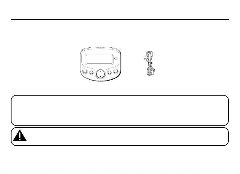
Make sure your package includes the following items:
new
delete
options
Caller ID unit
dial
flash
review
Telephone line cord
VERY IMPORTANT: You must call your local phone company and tell the representative that you have a Caller
ID/Call Waiting device that integrates the two services (called Type II Caller ID). Some phone companies aren't
equipped to integrate the two services, which means only the Caller ID part of your unit will work. The phone
companies that do have the ability to integrate Call Waiting and Caller ID must program your telephone line so
the two services work together. You need to call and ask them to do this.
CAUTION: When using telephone equipment, there are basic safety instructions that should always be
followed. Refer to the IMPORTANT SAFETY INSTRUCTIONS provided with this product and save them
for future reference.
6
Page 7

INTRODUCTION TO CID SERVICE
Congratulations on purchasing this Caller ID unit.
This system has been designed to be simple to
use, however, you can reach its full potential
more quickly by taking a few minutes to read this
User’s Guide.
This Caller ID system is a multifunction product for
use with the Call Waiting and Caller ID services
available from your local telephone company.
YOUR CALLER ID CALL WAITING
UNIT ALLOWS YOU TO:
• View the telephone number and name of a
waiting caller (Call Waiting Caller ID).
• Review all calls to your phone; the unit stores
up to 70 call records.
• Screen unwanted calls, eliminate harassment
from annoying calls, or to get prepared before
answering a call.
INSTALLATION
IMPORTANT INSTALLATION
INFORMATION
• Never install telephone wiring during a
lightning storm.
• Never touch uninsulated telephone wires or
terminals, unless the telephone line has been
disconnected at the network interface.
• Use caution when installing or modifying
telephone lines.
MODULAR JACK REQUIREMENTS
You need an RJ11C type modular jack,
which is the most common type of phone
jack and might look like the one pictured
here. If you don’t have a modular jack, call
your local phone company to find out
how to get one installed.
7
Page 8
INSTALLING THE BATTERIES
Your Caller ID uses 3 AA-size alkaline batteries (not
included) for receiving and storing Caller ID records.
IMPORTANT: You have approximately 60 seconds
to replace the batteries before the call records are
lost. Please read the instructions before replacing
the batteries and have them ready to be inserted
beforehand. You may want to write down any stored
information you do not want erased.
1. If the telephone line cord or a phone is
connected to the unit, disconnect it from the
unit.
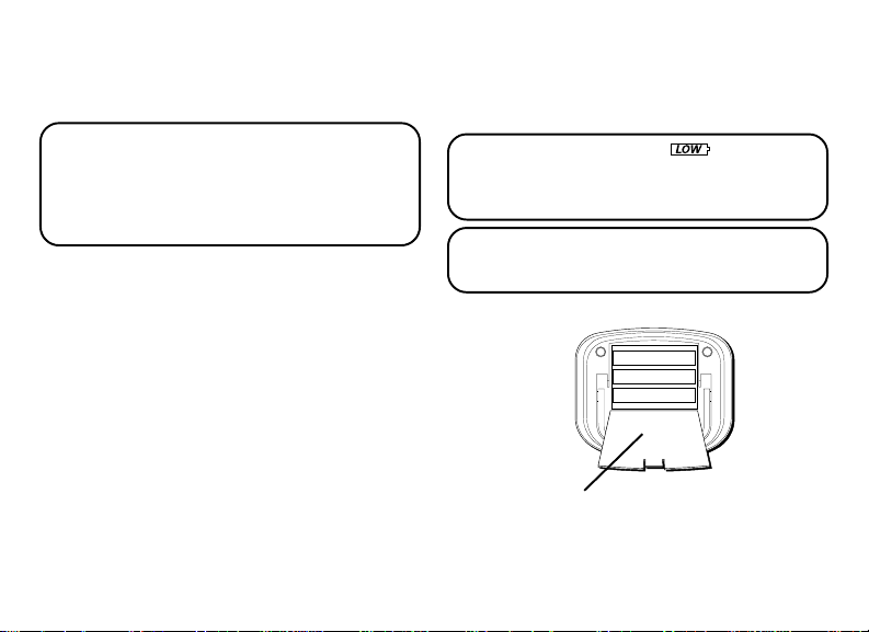
2. Use a screwdriver or other flat tool to open the
battery compartment door.
3. Insert 3 AA-size alkaline batteries (not
included) as shown on the diagram in the
battery compartment.
8
4. Replace the battery compartment door
securely.
5. If the line cord was previously connected,
reattach it to the unit.
NOTE: If the low battery icon appears in the
display, you need to replace the batteries. It is
important that you replace the batteries as soon as
possible in order to maintain Caller ID operation.
IMPORTANT: If you’re not going to use the unit
for more than 30 days, remove the batteries because
they can leak and damage the unit.
Battery door
Page 9
CONNECTING A TELEPHONE
2
4
3
5
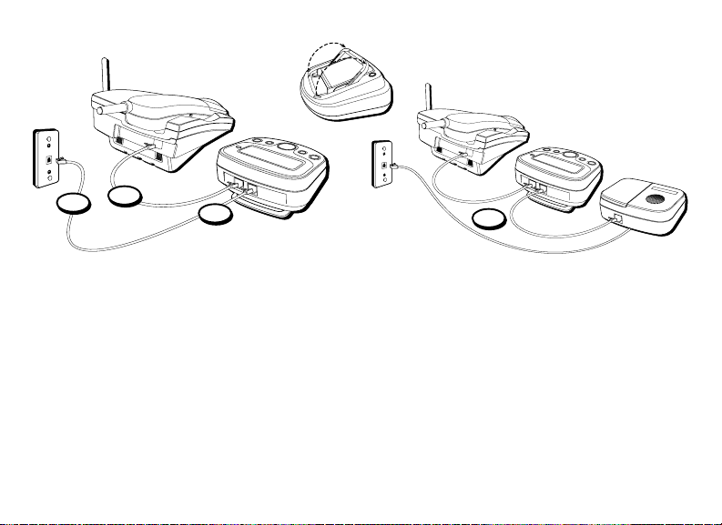
1. To install this unit, disconnect your telephone
by removing the plug at the end of its line cord
from the telephone wall jack.
2. Plug the line cord from your telephone into the
jack marked PHONE on this unit.
3. Plug one end of the line cord supplied with
your Caller ID unit into the jack marked LINE
on this unit.
4. Plug the remaining end of the line cord
connected to this unit’s LINE jack into the
telephone wall jack.
5. If this unit is connected with an answering
machine, please refer to the following drawing
and set your answering machine to answer the
phone for at least 2 rings. This will assure that
this unit will receive the CID information
correctly.
9
Page 10
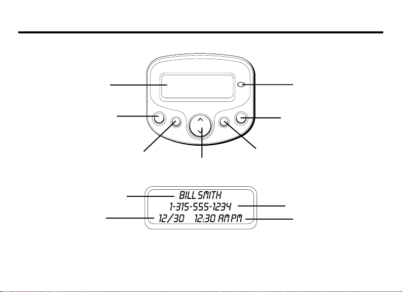
OPTIONS MENU
10
display
delete button
Caller ID name
Date
delete
options button
options
review
review button
new
NEW CALL
indicator
dial
flash
dial button
flash button
Caller ID number
Time
Page 11

If there is a transparent overlay label covering the
display, remove it prior to use.
When applying power for the first time, the
summary screen appears.
NOTE: Proceed immediately to change any of the
following factory preset settings as required.
1. To enter the options menu, press the options
button.
OPTIONS MENU SET
2. At this point you can press either arrow button
to scroll through 5 menu screens:
CID LANGUAGE (default English)
LCD CONTRAST (default 3)
LOCAL AREA CODE (default ---)
10 DIGIT ACs (default --- --- ---)
EXIT
• You have 10 seconds following any key press
before the unit will automatically return to the
summary screen.
NOTE: You can save a change and exit the options
menu by pressing the options button.
^ or v appears.
SETTING THE CID LANGUAGE
This adjustment let's you view the Caller ID
messages in English, French, or Spanish.
1. To enter the options menu, press the options
button.
OPTIONS MENU SET
2. Press the up or down arrow button until
LANGUAGE
3. Press the options button to show the current
language setting. The default is English.
4. Press the up or down arrow button to change
the language.
5. Press options again to store the language and
return to the
appears.
CID LANGUAGE
^ or v appears.
CID
display.
SETTING THE LCD CONTRAST
This adjustment allows you to adjust the contrast
and viewing angle of the display.
1. To enter the options menu, press the options
button.
OPTIONS MENU SET
2. Press the up or down arrow button until
CONTRAST
appears.
^ or v appears.
LCD
11
Page 12

3. Press the options button to show the current
contrast setting. There are 5 levels of contrast,
with the default set to 3.
4. To decrease the contrast, press the down arrow
button. To increase, press the up arrow button.
5. Press options again to store the contrast setting
and return to the
LCD CONTRAST
display.
SETTING THE LOCAL AREA CODE
The Caller ID unit uses the programmed area
code to determine the number format to display
when a valid Caller ID signal is received. The
programmed area code is also used for the Dial
Back feature.
1. To enter the options menu, press the options
button.
OPTIONS MENU SET
2. Press the up or down arrow button until
AREA CODE
3. Press the options button to show the current
local area code. The default is ---. The first digit
flashes, indicating it is ready to accept the area
code entry.
12
appears.
^ or v appears.
LOCAL
4. Press the down arrow button to choose 9-0 for
the first digit.
5. When the desired number is flashing, press the
up arrow button to advance to the next digit.
6. Repeat steps 4 and 5 until all the digits for your
area code are correct.
7. Press options again to store the local area code
and return to the
NOTE: If you make a mistake while setting the local
area code, you can delete the displayed area code
by pressing the delete button.
LOCAL AREA CODE
display.
SETTING THE 10-DIGIT REGIONAL
AREA CODES
Depending on your telephone company and your
location, it may be required that you dial a
10-digit number (area code + local number) to
complete some calls. You can store up to six 10digit regional area codes in this unit.
1. To enter the options menu, press the options
button.
OPTIONS MENU SET
^ or v appears.
Page 13

2. Press the up or down arrow button until
DIGIT AC's
3. Press the options button to show the current
regional area code. The default is --- --- ---. The
first digit flashes, indicating it is ready to
accept the area code entry.
4. Press the down arrow button to choose 9-0 for
the first digit.
5. When the desired number is flashing, press the
up arrow button to advance to the next digit.
6. Repeat steps 4 and 5 until all the digits for your
regional area code are correct.
7. Press options again to store the regional area
code and return to the
NOTE: If you make a mistake while setting the 10digit AC's, you can delete the selected set of the
area code by pressing the delete button.
appears.
10 DIGIT AC's
10
display.
EXITING THE OPTIONS MENU
1. Press the up or down arrow button until
EXIT SETUP
appears.
2. Press the options button to exit the options
menu.
OPERATION
RECEIVING CALLS
This unit has a built-in real time clock that
accurately keeps the current time and date. The
clock is automatically set and updated each time
Caller ID information is received.
IMPORTANT: Allow at least two rings to occur
prior to answering calls. This will assure that the
unit will receive the Caller ID information correctly.
• When the telephone is not in use and a new
call is received, the display displays the phone
number, the caller’s name, and time and date
of the call for 20 seconds. The
symbol comes on.
• The red NEW CALL indicator comes on,
confirming new calls have been received.
NEW
(new call)
13
Page 14

• After 20 seconds without activity, the display
changes to the summary screen which remains
until another call is received or any button is
pressed. You can see the total number of calls
stored and how many of the new calls have not
been reviewed.
FLASH
Press the flash button instead of using the hook
switch to activate customer calling services such
as call waiting or call transfer, which are provided
by your local telephone company.
CALL WAITING DISPLAY
To utilize the full capabilities of this unit, you must
subscribe to Caller ID with name and number
service and Call Waiting with Caller ID service. This
unit lets you know when a call is waiting, as well as
who is calling, before you answer.
This unit cannot provide Caller ID and Call
Waiting features unless you are subscribed to
receive the services from your local telephone
14
company. Check with your local telephone
company to confirm both of these services are
available. If you only have Caller ID service, this
unit will not receive and display Call Waiting with
Caller ID information. If you have Call Waiting
Caller ID service, a tone alerts you there is a new
call coming while you are on an existing call. You
will experience a short period of silence as the
Caller ID information is processed by the unit.
• When a call waiting signal is received,
WAITING
and telephone number of the person calling
appears in the display for 20 seconds.
• Press flash to put the existing call on hold and
answer the new call.
• When you finish with the new call, press flash
to return to the original call.
• If you choose not to answer the new call, the
Call Waiting ID information is stored for future
reference.
flashes in the display. Then the name
CALL
Page 15

TIP: If you choose not to use any of the Call
Waiting options, you may simply ignore the call
waiting beeps and continue your conversation. The
person calling will hear a continuous ring, as if you
are not home, or may be transferred to a voice mail
account if available.
IMPORTANT: To use the Call Waiting feature of
this unit, the phone you are using must be
connected directly to the unit.
REVIEWING CALL RECORDS
• When the red NEW CALL indicator is on, you
have received new incoming calls. Next to
the
NEW
Press the up or down arrow button to review
the stored calls. After the new call records
are reviewed, the indicator turns off.
• When you reach the end of the call records, the
display shows
have reviewed all the records.
symbol is the total number of calls.
START/END
, confirming you
DELETING CALL RECORDS
TO DELETE AN INDIVIDUAL CALL
When reviewing calls, you may delete an individual
call by pressing the delete button once. The
contents of the display will be erased and the
remaining Caller ID records are renumbered.
TO DELETE ALL CALLS
1. When reviewing calls, you may delete all calls
by pressing and holding the delete button for
more than 3 seconds.
the display.
2. Press delete again to confirm.
DELETE ALL?
appears in
DIAL
If your phone and Caller ID unit is connected to a
touch tone line, you may use the dial button to
dial any telephone number shown in the display.
IMPORTANT: All phones on the line must be on
the hook for this feature to work.
15
Page 16

CHANGING THE NUMBER FORMAT
The options button lets you change the format of
the displayed number. The available formats are
as follows.
7-digit 7-digit telephone number.
10-digit 3-digit area code+ 7-digit telephone
11-digit long distance code “1” + 3-digit area
1. Use the arrow buttons to scroll to the number
2. Press the dial button. If the number is 7, 10, or
3. If the phone is off the hook, the display counter
16
number.
code + 7-digit telephone number.
you want to call back.
11 digits,
NOTE: If the number does not dial as shown, press
the options button. Repeat if necessary, until the
correct number of digits is shown.
counts down from three to zero seconds. During
this time you may press the options button and
adjust the number format. When you are
fininshed the number automatically dials.
ADJUST
shows in the display.
IMPORTANT: All phones on the line must be on
the hook for this feature to work.
4. If the phone is on the hook, the counter counts
down from ten to zero seconds. During this
time, you may press the options button to
adjust the number format. Pick up the handset
before the phone turns to idle mode and the
phone number automatically dials.
5. Press the flash button to exit and return to
review mode.
CALLER ID MESSAGES
The following special messages indicate the
status of a message or the unit:
NO CALLS
UNKNOWN
CALLER
The call record log is empty.
The incoming call does not
have Caller ID service or its
service area is not linked to
yours. If
UNKNOWN CALLER
appears along with a calling
number, the name
information for that number
is not available.
Page 17

BLOCKED CALL
NO DATA
START/END
The caller is registered as
“Private Number” and the
Caller ID information is
withheld.
No Caller ID signal was
detected, or Caller ID service
was not activated.
Indicates you are at the
beginning or the end of the
call record log.
Battery power is low.
TROUBLESHOOTING TIPS
NO INFORMATION IS SHOWN AFTER THE
PHONE RINGS
• Be sure to wait until the second ring before
answering.
• Check all cabling to make sure all connections
are secure and not damaged.
• Did you order Caller ID service from your local
telephone company? This unit requires that you
subscribe to Caller ID service in order to work.
GENERAL PRODUCT CARE
To keep your Caller ID unit working and looking
good, follow these guidelines:
• Avoid putting it near heating appliances and
devices that generate electrical noise (for
example, motors or fluorescent lamps).
• DO NOT expose to direct sunlight or moisture.
• Avoid dropping the unit and other rough
treatment.
• Clean with a soft cloth.
• Never use a strong cleaning agent or abrasive
powder because it will damage the finish.
• Retain the original packaging in case you need
to ship it at a later date.
17
Page 18

INDEX
B
Before You Begin 6
C
Call Waiting Display 14
Caller ID Messages 16
Changing the Number Format 16
Connecting a Telephone 9
D
Deleting Call Records 15
Dial 15
E
Equipment Approval Information
2
Exiting the Options Menu 13
F
Features 4
Flash 14
18
G
General Product Care 17
I
Important Installation Information
7
Installation 7
Installing the Batteries 8
Interference Information 3
Introduction to CID Service 7
L
Limited Warranty 19
M
Modular Jack Requirements 7
O
Operation 13
Options Menu 10
P
Parts Checklist 6
R
Receiving Calls 13
Reviewing Call Records 15
S
Setting the 10-digit Regional Area
Codes 12
Setting the CID Language 11
Setting the LCD Contrast 11
Setting the Local Area Code 12
T
To Delete All Calls 15
To Delete an Individual Call 15
Troubleshooting Tips 17
Y
Your Caller ID Call Waiting Unit
Allows You To 7
Page 19

LIMITED WARRANTY
What your warranty covers:
• Defects in materials or workmanship.
For how long after your purchase:
• One year, from date of purchase.
(The warranty period for rental units begins with the first rental or 45 days
from date of shipment to the rental firm, whichever comes fir st.)
What we will do:
• Provide you with a new or, at our option, a refurbished unit. The exchange unit
is under warranty for the remainder of the original product’s warranty period.
How you get service:
• Properly pack your unit. Include any cables, etc., which were originally
provided with the product. We recommend using the original carton and
packing materials.
• ”Proof of purchase in the form of a bill of sale or receipted invoice which is
evidence that the product is within the warranty period, must be presented
to obtain warranty service.” For rental firms, proof of first rental is also
required. Also print your name and address and a description of the defect.
Send via standard UPS or its equivalent to:
ATLINKS USA, Inc.
c/o Thomson multimedia Inc.
11721 B Alameda Ave.
• Pay any charges billed to you by the Exchange Center for service not
• Insure your shipment for loss or damage. ATLINKS accepts no liability in
• A new or refurbished unit will be shipped to you freight prepaid.
What your warranty
• Customer instruction. (Your Owner’s Manual provides information regarding
• Installation and setup service adjustments.
• Batteries.
• Damage from misuse or neglect.
Socorro, Texas 79927
covered by the warranty.
case of damage or loss.
does not
cover:
operating instructions and user controls. Any additional information, should
be obtained from your dealer.)
• Products which have been modified or incorporated into other products.
• Products purchased or serviced outside the USA.
• Acts of nature, such as but not limited to lightning damage.
Limitation of Warranty:
• THE WARRANTY STATED ABOVE IS THE ONLY WARRANTY APPLICABLE TO
THIS PRODUCT. ALL OTHER WARRANTIES, EXPRESS OR IMPLIED
(INCLUDING ALL IMPLIED WARRANTIES OF MERCHANTABILITY OR FITNESS
FOR A PARTICULAR PURPOSE) ARE HEREBY DISCLAIMED. NO VERBAL OR
WRITTEN INFORMATION GIVEN BY ATLINKS USA, INC., ITS AGENTS, OR
EMPLOYEES SHALL CREATE A GUARANTY OR IN ANY WAY INCREASE THE
SCOPE OF THIS WARRANTY.
• REPAIR OR REPLACEMENT AS PROVIDED UNDER THIS WARRANTY IS THE
EXCLUSIVE REMEDY OF THE CONSUMER. ATLINKS USA, INC. SHALL NOT BE
LIABLE FOR INCIDENTAL OR CONSEQUENTIAL DAMAGES RESULTING FROM
THE USE OF THIS PRODUCT OR ARISING OUT OF ANY BREACH OF ANY
EXPRESS OR IMPLIED WARRANTY ON THIS PRODUCT. THIS DISCLAIMER OF
WARRANTIES AND LIMITED WARRANTY ARE GOVERNED BY THE LAWS OF
THE STATE OF INDIANA. EXCEPT TO THE EXTENT PROHIBITED BY APPLICABLE
LAW, ANY IMPLIED WARRANTY OF MERCHANTABILITY OR FITNESS FOR A
PARTICULAR PURPOSE ON THIS PRODUCT IS LIMITED TO THE APPLICABLE
WARRANTY PERIOD SET FORTH ABOVE.
How state law relates to this warranty:
• Some states do not allow the exclusion nor limitation of incidental or
consequential damages, or limitations on how long an implied w arranty
lasts so the above limitations or exclusions may not apply to you.
• This warranty gives you specific legal rights, and you also may have other
rights that vary from state to state.
If you purchased your product outside the USA:
• This warranty does not apply. Contact your dealer for warranty information.
19
Page 20

Model 29096
15861690 (Rev. 1 E/S)
02-20
Printed in China
ATLINKS USA, Inc.
101 West 103rd Street
Indianapolis, IN 46290
© 2002 ATLINKS USA, Inc.
Trademark(s) ® Registered
Marca(s) Registrada(s)
Page 21

Identificador de Llamadas con Llamada
en Espera (Caller ID with Call Waiting)
Guía del Usuario
Creamos cosas buenas para la vida.
29096
Page 22

INFORMACIÓN SOBRE LA APROBACIÓN DE EQUIPO
El equipo de su teléfono esta aprobado para la conexión con la red Telefónica Pública (Public Switched Telephone Network) y cumple
con los requisitos establecidos en las secciones 15 y 68 de las Reglas y Regulaciones de la FCC y con los Requerimientos Técnicos para
Equipos de Terminales Telefónicas (Technical Requirements for Telephone Terminal Equipment), publicado por ACTA.
1 Notificación a la Compañía Telefónica Local
En la parte de abajo de este equipo hay una etiqueta que indica, entre otra información, el número de US y el Número de
Equivalencia de Timbres (REN) para este equipo. Usted debe, cuando sea requerido, proveer esta información a su compañía
telefónica.
El REN es útil para determinar el número total de artefactos que Ud. puede conectar a su línea telefónica, todavía asegurando que
todos estos artefactos sonarán cuando se llame su número telefónico. En la mayoría de las áreas (pero no en todas), el total de los
números REN de todos los artefactos conectados a una línea no debe exceder 5. Para estar seguro del número total de artefactos
que Ud. pueda conectar a su línea (determinado por el REN), Ud. deberá ponerse en contacto con su compañía telefónica local.
NOTAS:
• No se puede usar este equipo con un teléfono de previo pago proveído por la compañía telefónica.
• Las líneas compartidas son sujetas a las tarifas del estado, y por eso, es posible que Ud. no pueda usar su propio equipo
telefónico si Ud. estuviera compartiendo la misma línea telefónica con otros abonados.
• Se debe notificar la compañía telefónica cuando se desconecte permanentemente su teléfono de la línea.
2 Derechos de la Compañía Telefónica
Si su equipo causase algún problema en su línea que pudiera dañar la red telefónica, la compañía telefónica siempre que sea
posible le avisará de la posible interrupción temporal de su servicio. En caso que la compañía no pudiera avisarle de antemano y
hubiera necesidad de tomar tal acción, la compañía telefónica podrá interrumpir su servicio inmediatemente. En caso de tal
interrupción telefónica temporal la compañía debe : (1) darle aviso al momento de tal interrupción temporal de servico, (2)
concederle a Ud. la oportunidad de corregir la situación, (3) informarle a Ud. de sus derechos de presentar una questa a la
Comisión de acuerdo con los procedimientos dictados en la Subparte E de la Parte 68 de las Regulaciones y Reglas de la FCC.
La compañía telefónica puede hacer los cambios en sus instalaciones de comunicación, en equipos, en sus funcionamientos o
procedimientos que digne necesarios para el manejo de sus negocios y que no sean incompatibles con las Reglas y Regulaciones
de l a FCC. Si estos cambios pudieran alterar el uso o el funcionamiento de su equipo telefónico, la compañía telefónica deberá
darle aviso adecuado en escrito para que Ud. goce de un servico ininterrumpido.
El número de la US está ubicado en el fondo de la base
El numero REN esta ubicado en el fondo de la base
2
Page 23

INFORMACIÓN DE INTERFERENCIAS
Este artefacto cumple con la Parte 15 de las Reglas de la FCC. Su funcionamiento es sujeto a las dos condiciones siguientes: (l) Este
artefacto no puede causar interferencia dañosa, y (2) Este artefacto debe aceptar cualquier interferencia recibida, incluyendo
interferencia que puede causar un funcionamiento no deseado.
Este equipo ha sido probado y cumple con los límites para un artefacto digital de la Clase B, de conformidad con la Parte 15 de las
Reglas de la FCC. Estos límites han sido diseñados para proporcionar una protección razonable contra una interferencia dañosa que
pueda existir en una instalación doméstica.
Este equipo genera, usa y puede radiar la energía de frecuencia de una radio y, si no fuera instalado y usado de acuerdo con las
instrucciones, puede causar interferencia dañosa a las transmisiones radiales. Sin embargo, no hay garantía que la interferencia no
ocurrirá en una instalación en particular.
Si este equipo causa en efecto una interferencia dañosa a la recepción de la radio o de la televisión, lo cual puede ser determinado
apagando y prendiendo el equipo, le animamos a Ud. de tratar de corregir la interferencia por medio de una (o más) de las sugerencias
siguientes:
• Cambie la posición o la ubicación de la antena (quiere decir la antena de la radio o de la televisión que está
recibiendo la interferencia).
• Cambie la posición o cambie la ubicación y aumente la distancia entre el equipo de telecomunicaciones y la
antena receptora de la radio o de la televisión que está recibiendo la interferencia.
• Conecte el equipo de telecomunicaciones a una toma en un circuito diferente del circuito al cual la antena
receptora esté conectada.
Si estas medidas no eliminan la interferencia, favor de consultar a su distribuidor o a un técnico de radio/televi
sión experto por otras sugerencias. También, la Comisión Federal de Comunicaciones (FCC) ha preparado un folleto muy útil, “How To
Identify and Resolve Radio/TV Interference Problems” (“Como Identificar y Resolver Problemas de Interferencia de Radio/Televisión”).
Este folleto se puede obtener del U.S. Goverment Printing Office, Washington, D.C. 20402. Favor de especificar el número
004-000-00345-4 cuando haga su pedido.
ATTENTION:
RIESGO DE SACUDIDA
ADVERTENCIA: PARA PREVENIR
EL RIESGO DE UNFUEGO O DE UNA
SACUDIDA ELECTRICA, NO EXPONGA
ESTE APARATO A LA LLUVIA O A LA
HUMEDAD.
ELÉCTRICA NO ABRA
EL RELÁMPAGO Y LA
PUNTA DE FLECHA
DENTRO DEL TRIÁNGULO
ES UNA SEÑAL DE
ADVERTENCIA,
ALERTÁNDOLE A UD. DE
QUE HAY "VOLTAJE
PELIGROSO" DENTRO DEL
PRODUCTO.
CUIDADO: PARA REDUCIR
EL RIESGO DE UNA SACUDIDA
ELÉCTRICA, NO QUITE LA
CUBIERTA (O PARTE
POSTERIOR) NO USE PARTES
DE REPUESTO DENTRO.
CONSULTE A ALGUNA
PERSONA CALIFICADA DEL
SERVICIO DE REPARACIONES.
VEA ADVERTENCIA EN LA PARTE POSTERIOR/BASE DEL PRODUCTO.
EL SIGNO DE
EXCLAMACIÓN DENTRO
DEL TRIÁNGULO ES UNA
SEÑAL DE
ADVERTENCIA,
ALTERTÁNDOLE A UD. DE
QUE EL PRODUCTO, TRAE
INCLUCIDO,
INSTRUCTIONES MUY
IMPORTANTES.
3
Page 24

FUNCIONES
• Muestra el nombre y el número de la persona que llama,
como también la hora y fecha de la llamada.*
• Muestra el nombre y número de la persona que llama en
la Llamada en Espera.
• Pantalla de tres líneas
• Visor con tres idiomas a elegir- Inglés, Francés y Español.
• Caracteres de 15 matriz de puntos (dot matrix) para
servicio de Nombre y Número de la persona que llama.
• Muestra el número total de llamadas recibidas en
modalidad de alerta. Almacena la información del
Identificador de Llamadas (CID) hasta para 70 archivos
de nombre y número del CID.
• Marca el número telefónico con el código de área de
larga distancia ya incluído.
• Doble botón que le permite recorrer hacia adelante o
atrás para revisar datos de llamadas.
• Control de contraste electrónico.
4
• Botón para borrar que le permite borrar datos de
llamadas individuales o colectivas.
• Clave de área programable.
• Indicador de llamadas nuevas.
• Indicación de Llamada Desconocida, Llamada Privada,
Error, y No Información Enviada.
• Reloj con la hora real.
* Requiere que su compañía telefónica le provea con el
servicio de Identificador de Llamadas y el servicio de
Nombre y Número.
Page 25

TABLA DE CONTENIDO
INFORMACIÓN SOBRE LA APROBACIÓN DE
EQUIPO ............................................2
INFORMACIÓN DE INTERFERENCIAS ............ 3
UNCIONES .......................................... 4
F
NTES DE COMENZAR ............................ 6
A
LISTA DE PARTES .............................................. 6
INTRODUCCIÓN AL SERVICIO DE
IDENTIFICADOR DE LLAMADAS .............. 7
SU T ELÉFONO CON IDENTIFICADOR DE LLAMADA
ESPERA LE PERMITE ...................................... 7
EN
INSTALACIÓN ........................................ 7
INFORMACIÓN IMPORTANTE PARA LA INSTALACIÓN .... 7
REQUERIMIENTOS DE CONTACTO MODULAR ............ 7
PARA INSTALAR LAS BATERÍAS ............................. 8
PARA CONECTAR EL T ELÉFONO ............................. 9
MENÚ DE OPCIONES ........................... 10
PROGRAMACIÓN DEL IDIOMA PARA EL
IDENTIFICADOR DE LLAMADAS ............................. 11
PROGRAMACIÓN DEL CONTRASTE DEL VISOR ......... 11
PROGRAMACIÓN DEL CÓDIGO DE AREA LOCAL ...... 12
PROGRAMACIÓN DEL CÓDIGO DE AREA REGIONAL
10 DÍGITOS ................................................ 12
DE
PARA SALIR DEL MENU DE OPCIONES ................ 13
OPERACIÓN ........................................ 13
PARA RECIBIR LLAMADAS ................................. 13
FLASH (SERVICIOS ESPECIALES) ......................... 14
VISOR DE LLAMADA EN ESPERA ......................... 14
PARA REVISAR ARCHIVOS ................................. 14
PARA BORRAR ARCHIVOS ................................. 15
PARA BORRAR UNA LLAMADA INDIVIDUAL ....... 15
PARA BORRAR TODAS LAS LLAMADAS ............. 15
MARCAR ........................................................ 15
PARA CAMBIAR EL FORMATO DE NÚMEROS ......... 15
MENSAJES DEL IDENTIFICADOR DE
LLAMADAS ..................................... 16
ETECCIÓN DE AVERÍAS ....................... 17
D
CUIDADO GENERAL DEL PRODUCTO ........ 17
ÓMO OBTENER SERVICIOS DE
C
MANTENIMIENTO ............................. 17
ÌNDICE ............................................... 18
ARANTÍA LIMITADA ............................ 19
G
5
Page 26

ANTES DE COMENZAR
LISTA DE PARTES
Asegúrese de que su paquete incluye los siguientes artículos:
new
delete
options
Aparato para Identificación de Llamadas
MUY IMPORTANTE: Usted tiene que llamar a su compañía de teléfonos local y debe informar al representante de que usted tiene
un aparato que integra los dos servicios: de Identificador de Llamadas y Llamada en Espera en uno (también conocido como
Identificador de Llamadas Tipo II). Algunas compañías telefónicas no están equipadas para integrar los dos servicios, lo cual
implica que unicamente funcionará la parte de su aparato para Identificador de Llamadas. Las compañías telefónicas que tienen la
capacidad de integrar Llamada en Espera e Identificador de Llamadas deben programar su línea telefónica para que ambos
dial
flash
review
Cable de línea telefónica
servicios funcionen juntos. Usted tiene que llamar y pedirles que así lo hagan.
CUIDADO: Cuando utilice equipo telefónico, hay instrucciones básicas de seguridad que siempre deben seguirse.
Refiérase a la guía de INSTRUCCIONES DE SEGURIDAD IMPORTANTES provista con este producto y guárdela
para referencia futura.
6
Page 27

INTRODUCCIÓN AL SERVICIO DE
IDENTIFICADOR DE LLAMADAS
Felicitaciones en la compra de su aparato Identificador
de Llamadas. El sistema ha sido diseñado para ser fácil
de usar. Sin embargo, usted puede aprovechar al
máximo su potencial si se toma unos minutos para leer
esta Guía del Usuario.
Este sistema con Identificador de Llamadas es un
producto con múltiples funciones para ser usado con los
servicios de Llamada en Espera e Identificador de
Llamadas que son disponibles a través de su compañía
telefónica.
INSTALACIÓN
INFORMACIÓN IMPORTANTE PARA LA
INSTALACIÓN
• Nunca instale el cableado del teléfono durante una
tormenta de relámpagos.
• Nunca toque alambres telefónicos o terminales que
no estén aislados, a menos que la línea telefónica
haya sido desconectada en la interfaz de la red.
• Sea cuidadoso cuando instale o modifique líneas
telefónicas.
SU TELÉFONO CON IDENTIFICADOR
LLAMADA EN ESPERA LE PERMITE:
DE
• Ver el número telefónico y el nombre de la persona
que llama (Identificador de Llamada en Espera).
• Revisar todas las llamadas recibidas; el aparato
almacena hasta 70 archivos de llamadas.
• Filtrar llamadas no deseadas, eliminar llamadas
molestas, o prepararse antes de contestar una
llamada.
REQUERIMIENTOS DE CONTACTO
MODULAR
Para conectar el teléfono se necesita un
enchufe modular telefónico RJ11C, que es el
tipo de enchufe más común y se parece al
ilustrado. Si usted no tiene este tipo de
enchufe, llame a su compañía telefónica
local para preguntar cómo conseguirlo.
7
Page 28

PARA INSTALAR LAS BATERÍAS
Su aparato Identificador de llamadas utiliza 3 pilas
alcalinas tamaño AA (no incluidas) para recibir y
almacenar archivos del Identificador de Llamadas.
IMPORTANTE: Usted tiene aproximadamente 60
segundos para reemplazar las baterías antes de que los
archivos de llamadas se pierdan. Por favor lea las
instrucciones antes de reemplazar las baterías y tenga
éstas listas de antemano para ser colocadas. Quizá
quiera tener escrita cualquier información almacenada
que usted no quiera que sea borrada.
1. Si el cable telefónico o el teléfono está conectado al
aparato, desconéctelo del aparato.
2. Utilice un destornillador o alguna otra herramienta
plana para abrir el compartimento de las baterías .
3. Coloque 3 baterías alcalinas tamaño AA (no
incluídas), como se muestra en el diagrama dentro
del compartimento de baterías.
4. Vuelva a colocar la puerta del compartimento y
asegúrese de que quede bien cerrada.
8
5. Si el cable de la línea estaba previamente conectado,
vuelva a conectar al aparato.
NOTA: Si el símbolo de baja batería aparece en la
pantalla, usted necesita cambiar las baterías. Es importante
que usted cambie las baterías tan pronto como le sea posible
para mantener la operación adecuada del Identificador de
Llamadas (Caller ID).
IMPORTANTE: Si usted no va a utilizar el aparato durante
más de 30 días, quite las baterías porque éstas pueden tener
fugas y dañar el aparato.
Puerta de las Baterías
Page 29

PARA CONECTAR EL TELÉFONO
2
4
3
5
1. Para instalar el aparato, desconecte su teléfono
sacando el enchufe del extremo del cable telefónico
del contacto en la pared.
2. Conecte el cable de la línea telefónica desde su teléfono
al contacto marcado “PHONE” en este aparato.
3. Conecte un extremo del cable telefónico, que viene
incluído en su empaque con el aparato de
Identificación de Llamadas, en un contacto marcado
“LINE” en el aparato.
4. Conecte el otro extremo del cable telefónico que ha
conectado ya en el contacto marcado “LINE”, en un
contacto de pared.
5. Si este aparato está conectado con un contestador,
por favor refiérase al siguiente diagrama y programe
su contestador para contestar el teléfono después de
por lo menos 2 timbres. Esto asegurará que el
aparato recibirá la información del Identificador de
Llamadas correctamente.
9
Page 30

MENÚ DE OPCIONES
Pantalla
delete
Botón para borrar (“delete”)
options
Botón para opciones (“options”)
Botón para revisar (“review”)
Nombre de la persona que llama
Fecha
Si hay una etiqueta transparente cubriendo el visor, por
favor quítela antes de usar el aparato.
Cuando pasa corriente por primera vez, la pantalla
sumario aparece.
10
new
Indicador de llamada
nueva (“new call”)
dial
flash
review
Botón para marcar (“dial”)
Botón para servicios (“flash”)
Número telefónico del Caller ID
Hora
NOTA: Proceda inmediatamente a cambiar cualquiera de
las siguientes programaciones pre-establecidas de fábrica
que vienen con el aparato, como sea requerido.
1. Para entrar al menú de opciones, oprima el botón de
opciones. La indicación de opciones (“
MENU SET
^ ov ”) aparece en la pantalla.
OPTIONS
Page 31

2. En este punto usted puede oprimir cualquiera de los
botones de las flechas para recorrer las 5 pantallas de
menús:
Idioma del Identificador de Llamadas (“CID
LANGUAGE”) (pre-programado de fábrica en inglés)
Contraste del Visor (“CONTRAST”), (pre-programado
en el nivel 3)
Código de Area de Larga Distancia (“CODIG AREA
LOCA”) (pre-programado ---)
Código de Area de 10 dígitos (“COD AREA10 DIGI”),
(pre-programado --- --- ---)
EXIT (salida)
• Usted tiene 10 segundos después de oprimir
cualquier tecla antes de que el aparato vuelva
automaticamente a la pantalla sumario.
NOTA: Usted puede salvar un cambio y salir del Menú de
opciones, simplemente oprimiendo el botón “options.”
PROGRAMACIÓN DEL IDIOMA PARA EL
IDENTIFICADOR DE LLAMADAS
Esta función le permite ver los mensajes del
Identificador de Llamadas en inglés, francés o español.
1. Para entrar al menú de opciones, oprima el botón de
opciones. La indicación de opciones (“
MENU SET
^ ov ”) aparece en la pantalla.
OPTIONS
2. Oprima el botón con la flecha hacia arriba o hacia
abajo hasta que aparezca la indicación de idioma en
la pantalla (“
3. Oprima el botón de opciones para mostrar la
programación actual de idioma. La programación de
fábrica es inglés.
4. Oprima el botón con la flecha hacia arriba o hacia
abajo para cambiar el idioma.
5. Oprima nuevamente el botón de opciones para
almacenar el idioma y volver a la pantalla de idioma
de la pantalla (“
CID LANGUAGE
CID LANGUAGE
”).
”).
PROGRAMACIÓN DEL CONTRASTE DEL
VISOR
Esta función le permite ajustar el nivel de contraste y el
ángulo de visión de la pantalla.
1. Para entrar al menú de opciones, oprima el botón de
opciones. La indicación de opciones (“
MENU SET
2. Oprima el botón con la flecha hacia arriba o hacia
abajo hasta que aparezca la indicación de contraste
de la pantalla (“
3. Oprima el botón para opciones (“
mostrar el nivel de contraste actualmente
programado. Hay 5 niveles de contraste, y el nivel
pre-programado es 3.
^ ov ”) aparece en la pantalla.
CONTRASTE
”).
OPTIONS
OPTIONS
”) para
11
Page 32

4. Para disminuir el contraste, oprima el botón de la
flecha hacia abajo. Para aumentarlo, el botón de la
flecha hacia arriba.
5. Oprima nuevamente el botón para opciones
(“options”) para almacenar el nivel de contraste y
regresar a la pantalla que indica
CONTRASTE
.
PROGRAMACIÓN DEL CÓDIGO DE AREA
LOCAL
El aparato Identificador de Llamadas usa la clave de área
programada para determinar qué formato de número
debe mostrar cuando una señal válida del Identificador
de Llamadas es recibida. La clave de área programada
también se usa para la función de Volver a Marcar el
Número que Llamó.
1. Para entrar al menú de opciones, oprima el botón de
opciones. La indicación de opciones (“
MENU SET
2. Oprima el botón con la flecha hacia arriba o hacia
abajo hasta que aparezca la indicación de clave de
área local (“
3. Oprima el botón para opciones (“options”) para
mostrar el código de área actualmente programado.
El código de área por omisión o pre-programado es ---.
El primer dígito parpadea, indicando que está listo
para aceptar la inscripción de la clave de área.
^ ov ”) aparece en la pantalla.
CODIG AREA LOCA
12
OPTIONS
”).
4. Oprima el botón de la flecha hacia abajo para escoger
entre el 9 y 0 para el primer dígito.
5. Cuando el número deseado está parpadeando,
oprima el botón de la flecha hacia arriba para avanzar
al siguiente dígito.
6. Repita los pasos 4 y 5 hasta que todos los dígitos
para su código de área estén correctamente inscritos.
7. Oprima nuevamente el botón para opciones
(“options”) para almacenar el código de área y
regresar a la pantalla que indica
NOTA: Si usted comete un error mientras programa su código
de área, usted puede borrar el código de área mostrado
simplemente oprimiendo el botón para borrar ("delete").
CODIG AREA LOCA
.
PROGRAMACIÓN DEL CÓDIGO DE
AREA REGIONAL DE 10 DÍGITOS
Dependiendo de su compañía telefónica y de su
localización, puede requerirse que usted marque un
número de 10 dígitos (clave de área + número local)
para completar algunas llamadas. Usted puede
almacenar hasta seis claves de área regional de 10
dígitos en este aparato.
1. Para entrar al menú de opciones, oprima el botón de
opciones. La indicación de opciones (“
MENU SET
^ ov ”) aparece en la pantalla.
OPTIONS
Page 33

2. Oprima el botón con la flecha hacia arriba o hacia
abajo hasta que aparezca la indicación de clave de
área (“
COD AREA 10 DIGI
3. Oprima el botón “options” para mostrar el código de
área regional actual. El código pre-programado es ---
--- ---. El primer dígito parpadea, indicando que está
listo para aceptar la inscripción de la clave de área.
4. Oprima el botón de la flecha hacia abajo para escoger
entre el 9 y 0 para el primer dígito.
5. Cuando el número deseado está parpadeando,
oprima el botón de la flecha hacia arriba para avanzar
al siguiente dígito.
6. Repita los pasos 4 y 5 hasta que todos los dígitos para su
código de área regional estén correctamente inscritos.
7. Oprima nuevamente el botón para opciones
(“options”) para almacenar el código de área regional
y regresar a la pantalla que indica
NOTA: Si usted comete un error mientras programa los 10
dígitos del código de área, usted puede borrar el grupo
seleccionado de código de área simplemente oprimiendo el
botón para borrar ("delete").
”).
COD AREA 10 DIGI
PARA SALIR DEL MENU DE OPCIONES
1. Oprima el botón de la flecha hacia arriba o hacia
abajo hasta que aparezca la indicación de salida
(“
SALIDA PROGRAMAC
2. Oprima el botón "options" para salir del menú de
opciones.
”).
OPERACIÓN
PARA RECIBIR LLAMADAS
Este aparato tiene un reloj integrado que mantiene la
hora y la fecha actual correctamente. El reloj es
programado automáticamente y se pone al día cada vez
que se recibe información del Identificador de Llamadas.
IMPORTANTE: Deje sonar el teléfono por lo menos dos
veces antes de contestar la llamada. Esto asegurará que el
aparato reciba la información del Identificador de Llamadas
correctamente.
• Cuando el teléfono no está en uso y se recibe una
nueva llamada, la pantalla muestra durante 20
segundos el número telefónico, el nombre de la
persona que llama, y la hora y fecha de la llamada. El
símbolo de llamada nueva (“
.
• El indicador rojo de llamada nueva (“NEW CALL”) se
iluminará para confirmar que nuevas llamadas han
sido recibidas.
• Después de 20 segundos sin actividad, la pantalla
cambia a la pantalla sumario, la cual permanece
hasta que otra llamada es recibida o cualquier botón
es oprimido. Usted puede ver el número total de
llamadas almacenadas y cuántas de las llamadas
nuevas no han sido revisadas.
NEW
”) aparece.
13
Page 34

FLASH (SERVICIOS ESPECIALES)
Oprima el botón de servicios especiales en lugar de utilizar
el gancho de colgar para activar servicios especiales como
llamada en espera o transferencia de llamadas, que son
provistas por su compañía telefónica local.
VISOR DE LLAMADA EN ESPERA
Para poder utilizar este aparato en su máxima
capacidad, usted debe suscribirse al servicio de
Identificador de Llamadas con nombre y número y
Llamada en Espera con servicio de Identificador de
Llamadas. Este aparato le anuncia cuando una llamada
está esperando, y también le anuncia quién es la
persona que llama antes de que usted conteste.
Este aparato no puede ofrecerle los servicios de
Identificador de Llamadas y Llamada en Espera a menos
que usted se suscriba y reciba estos servicios de su
compañía telefónica local. Verifique con su compañía
telefónica local para confirmar que estos dos servicios son
disponibles. Si usted únicamente tiene servicio de
Identificador de Llamadas, este aparato no recibirá y
mostrará la información de Identificador de Llamadas con
Llamada en Espera. Si usted tiene los servicios de
Identificador de Llamadas y Llamada en Espera, un tono
de alerta le indica que hay una llamada nueva entrando
mientras usted está en otra llamada. Usted experimentará
un pequeño rato de silencio mientras el aparato procesa la
información del Identificador de Llamadas.
14
• Cuando entra una señal de llamada en espera, la
indicación de llamada en espera (“
parpadea en la pantalla. Entonces el nombre y el
número telefónico de la persona que llama aparece
en la pantalla durante 20 segundos.
• Oprima el botón de servicios especiales (“flash) para
poner la conversación actual en espera y poder
contestar la llamada nueva.
• Cuando usted termina con esa llamada nueva,
oprima el botón “flash” para regresar a la llamada
original.
• Si usted prefiere no contestar la llamada nueva, la
información del Identificador de Llamadas es
almacenada para referencia futura.
SUGERENCIA: Si usted escoge utilizar cualquiera de las
opciones de la Llamada en Espera, usted puede
simplemente ignorar los tonos de llamada en Espera y
continuar su conversación. La persona que llama escuchará
tonos continuos, como si usted no estuviera en casa, o puede
ser transferida a un buzón de voz si éste es disponible.
IMPORTANTE: Para usar la función de Llamada en Espera
(Call Waiting) de este aparato, el teléfono que usted está
usando, debe estar conectado directamente al aparato.
MENSAJE
”)
PARA REVISAR ARCHIVOS
• Cuando aparece el indicador de llamada nueva
(“NEW”), quiere decir que usted ha recibido nuevas
llamadas entrantes. Junto al símbolo de llamada
Page 35

nueva (“NUEVA”) está el total de llamadas nuevas.
Oprima el botón de la flecha hacia arriba o hacia
abajo para revisar los archivos almacenados.
Después de que los archivos nuevos son revisados, el
indicador se apaga.
• Cuando usted llega al final de los archivos de
llamadas, la pantalla así se lo indica (“
FINAL
”) para confirmar que usted ha revisado todos
los archivos.
COMIENZO/
PARA BORRAR ARCHIVOS
PARA BORRAR UNA LLAMADA INDIVIDUAL
Mientras usted revisa sus archivos, usted puede borrar
las llamadas individuales oprimiendo el botón para
borrar (“delete”) una vez. El contenido de la pantalla
será borrado y los archivos del Identificador de
Llamadas restantes serán renumerados.
PARA BORRAR TODAS LAS LLAMADAS
1. Mientras usted revisa sus archivos, usted puede
borrar todas las llamadas individuales oprimiendo y
sosteniendo el botón para borrar (“delete”) durante
más de 3 segundos. La pantalla le preguntará si borra
todos los archivos (“
2. Oprima “delete” nuevamente para confirmar.
BORRAR TODO?
”).
MARCAR
Si su aparato con Identificador de Llamadas está
conectado a una línea con marcado por tono, usted
puede utilizar el botón para marcar (“dial”) cualquier
número telefónico que se muestra en la pantalla.
IMPORTANTE: Todos los teléfonos en la línea deben estar
colgados para que esta función sirva.
PARA CAMBIAR EL FORMATO DE
NÚMEROS
El botón "options" le permite cambiar el formato del
número mostrado. Los formatos disponibles son los
siguientes:
7-dígitos número telefónico de 7 dígitos
10-dígitos código de área de 3 dígitos +
11-dígitos código de larga distancia “1” +
1. Utilice los botones de las flechas para recorrer los
números a los que usted quiere devolver el llamado.
2. Oprima el botón para marcar. Si el número es de 7, 10
u 11 dígitos, la indicación de ajuste (“
AJUSTE
número telefónico de 7 dígitos.
código de área de 3 dígitos + número
telefónico de 7 dígitos.
”) aparece en la pantalla.
LEVANTE/
15
Page 36

NOTA: Si el número no se marca como está mostrado,
oprima el botón de opciones (“options”). Repita si es
necesario, hasta que aparezca el número correcto de dígitos.
3. Si el teléfono está descolgado, el temporizador de la
pantalla cuenta hacia abajo de tres a cero segundos.
Durante este tiempo, usted puede oprimir el botón de
opciones para ajustar el formato del número. Cuando
usted haya terminado, el número se marca
automáticamente.
IMPORTANTE: Todos los teléfonos en la línea deben estar
colgados para que esta función sirva.
4. Si el teléfono está descolgado, el temporizador de la
pantalla cuenta hacia abajo de diez a cero segundos.
Durante este tiempo, usted puede oprimir el botón de
opciones para ajustar el formato del número.
Levante el auricular antes de que el aparato entre en
modalidad de inactividad y el número telefónico se
marca automáticamente.
5. Oprima el botón de servicios (“flash”) para salir y
volver a la modalidad de revisión.
MENSAJES DEL IDENTIFICADOR
DE LLAMADAS
Los siguientes mensajes especiales indican el estado
actual de un mensaje o del aparato:
NINGUNA LLAMADA
16
El registro de llamadas está vacío.
DESCONOCIDO
LLAMDA PRIVADA
NINGUN MENSAJE
COMIENZO/ FINAL
La llamada entrante no tiene
servicio de Identificador de
Llamadas o su área de servicio no
está enlazada con la suya. Si la
indicación “
aparece junto con el número que
llama, la información de nombre
que corresponde a ese número no
está disponible.
La persona que llama está
registrada como “Número
Privado” y la
Identificador de Llamadas se
retiene.
No se detectó una señal del
Identificador de Llamadas, o el
servicio de Identificador de
Llamadas no fue activado.
Indica que usted está al principio
o al final del registro de
llamadas.
Advertencia de baja batería.
DESCONOCIDO
información del
”
Page 37

DETECCIÓN DE AVERÍAS
NO APARECE NINGUNA INFORMACIÓN EN EL
CUANDO ENTRA LA LLAMADA
VISOR
• Asegúrese que espera al segundo timbre antes de
contestar.
• Cheque todo el cableado para asegurarse de que
todas las conecciones están firmemente aseguradas
y no dañadas.
• ¿Ordenó usted el servicio de Identificador de
Llamadas (Caller ID) con su compañía telefónica
local? Este aparato requiere que usted se suscriba al
servicio de Identificador de Llamadas (Caller ID) para
que pueda funcionar.
CUIDADO GENERAL DEL PRODUCTO
Para mantener su Identificador de Llamadas funcionando y
conservándose bien, siga las siguientes recomendaciones:
• Evite poner este aparato cerca de aparatos que
producen calor y aparatos que generan ruido eléctrico
(por ejemplo, motores o lámparas fluorescentes).
• No lo exponga a la luz solar directa o a la humedad.
• Evite dejar caer el aparato y/o cualquier trato brusco.
• Limpie el aparato con un trapo suave.
• Nunca use un agente de limpieza fuerte ni un polvo
abrasivo, ya que esto dañará el acabado.
• Guarde el empaque original en caso de que usted
necesite enviar el aparato empacado en un futuro.
CÓMO OBTENER SERVICIOS DE
MANTENIMIENTO
Este producto puede únicamente ser reparado por el
fabricante o sus agentes de reparación autorizados.
Cualquier cambio o modificación no aprobados
expresamente por ATLINKS USA, Inc. podría ser motivo
de anulación de la autoridad del usuario para operar
este producto. Para recibir instrucciones sobre cómo
obtener servicios de mantenimiento, por favor consulte
la garantía incluida en esta Guía, o llame a Información
para el Usuario, 1-800-448-0329.
O envíe sus preguntas a:
ATLINKS USA, Inc.
Gerente, Servicio al Consumidor
P. O . B o x 1 9 7 6
Indianápolis, IN 46206
Adjunte su recibo al folleto, para futura referencia, o
anote la fecha en la que se compró o recibió este
producto como regalo. Esta información será valiosa si
se llegase a requerir durante el período de garantía.
Fecha de compra_____________________________________
Nombre de la tienda__________________________________
17
Page 38

ÌNDICE
A
Antes de Comenzar 6
C
Cómo Obtener Servicios de
Mantenimiento 17
Cuidado General del Producto 17
D
Detección de Averías 17
F
Flash (Servicios Especiales) 14
Funciones 4
G
Garantía Limitada 19
I
Información de Interferencias 3
Información Importante para la
Instalación 7
Información Sobre la Aprobación
de Equipo 2
18
Instalación 7
Introducción al Servicio de
Identificador de Llamada 7
L
Lista de Partes 6
M
Marcar 15
Mensajes del Identificador de
Llamadas 16
Menú de Opciones 10
O
Operación 13
P
Para Borrar Archivos 15
Para Borrar todas las
Llamadas 15
Para Borrar una Llamada
Individual 15
Para Cambiar el Formato de
Números 15
Para Conectar el Teléfono 9
Para Instalar las Baterías 8
Para Recibir Llamadas 13
Para Revisar Archivos 14
Para Salir del Menu de
Opciones 13
Programación del Código de Area
Local 12
Programación del Código de Area
Regional de 10 Dígitos 12
Programación del Contraste del
Visor 11
Programación del Idioma para el
Identificador de Llamadas 11
R
Requerimientos de Contacto
Modular 7
S
Su Teléfono con Identificador de
Llamada en Espera 7
V
Visor de Llamada en Espera 14
Page 39

GARANTÍA LIMITADA
Lo que cubre su garantía:
• Defectos de materiales o de trabajo.
Por cuánto tiempo después de la compra:
• Un año, a partir de la fecha de compra.
(El periodo de garantía para unidades arrendadas se inicia con la primera renta o
45 días de la fecha del embarque a la firma de arrendamiento, lo que ocurra
primero).
Lo que haremos:
• Proporcionarle una unidad nueva o, a nuestra opción, una reacondicionada. La
unidad de intercambio quedará bajo garantía por el resto del periodo de garantía
del producto original.
Cómo obtener servicio:
• Empaque bien la unidad, incluyendo todos los cables, etc., que originalmente
venían con el producto. Se recomienda usar el cartón y materiales de empaque
originales.
• “Prueba de compra como factura o recibo de compra, que ofrezca evidencia de
que el producto está dentro del periodo de garantía, debe ser presentado para
obtener servicio bajo garantía.” Para compañías de arrendamiento, se requiere
como evidencia el primer contrato de renta. También escriba claramente su
nombre, dirección y la descripción del defecto. Mande vía UPS o un servicio de
paquetería equivalente a:
ATLINKS USA, Inc.
c/o Thomson multimedia Inc.
11721 B Alameda Ave.
• Pague cualquier cargo que le facture el Centro de Intercambio por servicio que no
• Asegure su empaque para prevenir pérdida o daño. ATLINKS no acepta
• Un aparato nuevo o uno remozado se le enviará con los cargos pagados.
Lo que
• Instrucciones al cliente. (Su manual de propietario le proporciona la información
Socorro, Texas 79927
esté cubierto por garantía.
responsabilidad en caso de pérdida o daño.
no
cubre la garantía:
con respecto a las instrucciones de operación y los controles del usuario.
Cualquier información adicional debe obtenerse con su agente de ventas.
• Ajustes de instalación y de preparación del servicio.
• Baterías.
• Daño por mal uso o negligencia.
• Productos que han sido modificados o incorporados a otros productos.
• Productos comprados o que han recibido servicio fuera de los Estados Unidos.
• Desastres naturales, por ejemplo y sin limitarse a ellos, daños por relámpagos.
Limitaciones sobre la Garantía:
• LA GARANTÍA ESPECIFICADA ANTERIORMENTE ES LA ÚNICA GARANTÍA
APLICABLE A ESTE PRODUCTO. CUALQUIER OTRA GARANTÍA, EXPRESA O
IMPLÍCITA (INCLUYENDO TODAS LAS GARANTÍAS IMPLÍCITAS DE MERCADO O
DE SALUD PARA CUALQUIER PROPÓSITO) SON CONSIDERADAS NO VÁLIDAS.
NINGUNA INFORMACIÓN VERBAL O ESCRITA OTORGADA POR ATLINKS
USA,INC., SUS AGENTES, O EMPLEADOS SERÁ CONSIDERADA PARA CREAR
UNA GARANTÍA NI PARA AUMENTAR BAJO NINGUNA CIRCUNSTANCIA LA
COBERTURA DE ESTA GARANTÍA.
• LA REPARACIÓN O REEMPLAZO DE UN PRODUCTO COMO SE ESPECIFICA BAJO
ESTA GARANTÍA ES EL REMEDIO EXCLUSIVO DEL CONSUMIDOR. ATLINKS USA,
INC. NO SE HACE RESPONSIBLE POR DAÑOS INCIDENTALES, DAÑOS
DERIVADOS COMO CONSECUENCIA DEL USO DE ESTE PRODUCTO, O COMO
RESULTADO DEL INCUMPLIMIENTO DE CUALQUIER GARANTÍA IMPLÍCITA O
EXPRESA DE ESTE PRODUCTO. LA INVALIDEZ DE LAS GARANTÍAS O LAS
GARANTÍAS LIMITADAS ESTÁN REGLAMENTADAS POR LAS LEYES DEL ESTADO
DE INDIANA. EXCEPTO POR EL ALCANCE ESTABLECIDO POR LAS LEYES
APLICABLES, CUALQUIER GARANTÍA IMPLÍCITA DE MERCADO O DE SALUD
PARA CUALQUIER PROPÓSITO, EN ESTE PRODUCTO ES LIMITADA AL PERÍODO
DE GARANTÍA ESPECIFICADO ANTERIORMENTE.
Cómo se Relaciona la Ley Estatal a esta Garantía:
• Algunos estados no permiten la exclusión ni limitación de daño incidental o
derivado de alguna consecuencia, o la limitación con respecto al período de
tiempo que debe aplicarse para garantías implícitas, por lo tanto las limitaciones
y exclusiones mencionadas anteriormente pueden no ser aplicables para usted.
• Esta garantía le ofrece derechos legales específicos, y usted puede tener otros
derechos legales que varían de estado a estado.
Si compró su producto fuera de los Estados Unidos:
• Esta garantía no se aplica. Vea a su distribuidor para información sobre la
garantía.
19
Page 40

Modelo 29096
15861690 (Rev. 1 E/S)
02-20
Impreso en China
ATLINKS USA, Inc.
101 West 103rd Street
Indianapolis, IN 46290
© 2002 ATLINKS USA, Inc.
Trademark(s) ® Registered
Marca(s) Registrada(s)
 Loading...