

Page 1
WARNING
RISK OF SHOCK, DISCONNECT
POWER BEFORE INSTALLATION.
INSTALLATION INSTRUCTIONS
For P62- CP Carpet Plate and P62-TAR Adjusting Ring
CAUTION
THIS PRODUCT IS DESIGNED FOR USE IN NON-TRAFFIC AREAS ONLY. WHEN
LAYOUT REQUIREMENTS CHANGE AND COVERS ARE EXPOSED TO TRAFFIC,
REPLACE WITH P62TAR, PSOCP & P60COVER
P62-CP ASSEMBLY FOR RUBBER - BACK CARPET
1. ITEMS INCLUDED:
a. Carpet ring
b. Two split cover halves
c. Duplex receptacle partition
d. Three #12 - 24 x 1 inch long oval head steel adjusting screws
e. Two #6 - 32 x 3/8 inch long round head steel partition assembly screws
2. INSTALLATION:
2.1 Locate center of box opening, and if the oor covering is present, remove a 4- 3/4 inch
diameter section.
2.2 Break away concrete to expose protective cap. Remove and discard upper cap.
2.3 Fish power and /or telephone wires out of box. Install receptacle (not provided) on partition
using one of the #6- 32 x 3/8 round head screws. Wire the receptacle.
2.4 Install #6 - 32 x 3/8 round head screw in cover tab of oor box.
2.5 Insert receptacle - partition assembly into the oor box, pushing top u -slot of partition under
tab screw. Place the partition assembly over the forward projection in the box bottom, making
sure that it does not go beyond the two rear projections, and push the partition down to the
bottom of the box. Tighten the tab screw.
2.6 Place the carpet ring onto Floor Box Cover Mounting Ring and align three tabs with
countersunk clearance holes with the three tapped holes in the oor box cover mounting ring.
2.7 Install three #12- 24 x 1 adjusting screws through the countersunk holes into the tapped holes
below. Tighten screws all the way until carpet ring contacts the carpet.
2.8 Remove appropriate cable cutouts in cover halves.
2.9 Plug in access cords and assemble telephone connector, if applicable.
2.10 Install one cover half by inserting the straight edge of the cover under the two hold - down
tabs at each end of the opening in the carpet ring. Snap outer diameter of cover half down
into ring to secure it.
2.11 Follow same procedure for second cover half after making certain that cords t into
appropriate cut - outs.
P62-TAR ADJUSTING RING ASSEMBLY FOR USE WITH P62- CP
ASSEMBLY AND PLUSH CARPET
1. ITEMS INCLUDED:
a. Adjusting ring
b. Two #8 - 32 x 3/8 inch long round head steel hold - down screws
TA01350 B Page 1 of 2
Page 2
2. INSTALLATION:
Steps 2.1 through 2.5 are the same as above for use with rubber - back carpet.
2.6
Place P62-TAR adjusting ring (this assembly must be ordered separately) onto Floor Box Cover
Mounting Ring and align the three tabs with countersunk clearance holes with the three tapped
holes in the oor box cover mounting ring. To ensure proper alignment, the two locator tabs (see
sketch) should be parallel with the long side of the oor box.
2.7 Install three #12 - 24 x 1 adjusting screws (supplied with the P62 - CP assembly) through the
countersunk holes into the tapped holes below. Do not tighten screws, just engage two or
three turns.
2.8 Place carpet ring onto adjusting ring and align the three countersunk clearance holes with the
three #12 - 24 x 1 adjusting screws protruding from the adjusting ring. At the same time, the
two tabs in the carpet ring with small clearance holes should line up with the two tapped
holes in the adjusting ring.
2.9 Install two #8 - 32 x 3/8 round head screws through the two clearance holes in the carpet ring
and into the two tapped holes in the adjusting ring by lifting the adjusting ring up to engage
the screws. Tighten the two #8 - 32 x 3/8 screws securely so that the carpet ring bottoms on
the adjusting ring.
2.10 Tighten the three #12- 24 x 1 adjusting screws until the carpet ring reaches the desired
contact with the carpeted oor.
2.11 Remove appropriate cable cutouts in cover halves.
2.12 Plug in access cords and assemble telephone connector, if applicable.
2.13 Install one cover half by inserting the straight edge of the cover under the two hold down
tabs at each end of the opening in the carpet ring. Snap outer diameter of cover half down
into ring to secure it.
2.14 Follow same procedure for second cover half after making certain that cords t into
appropriate cutouts.
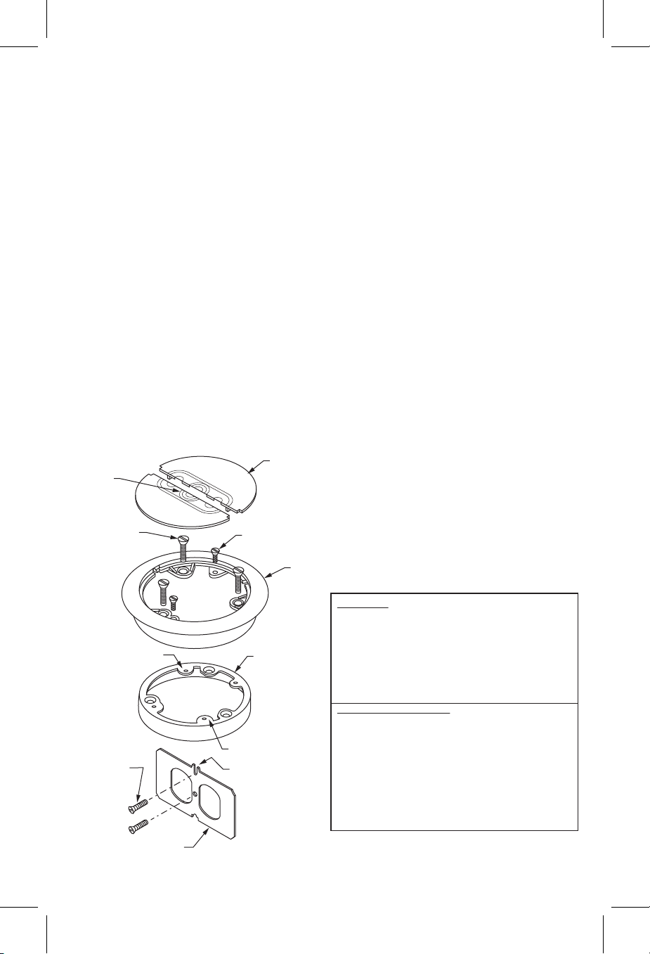
Split Cover Halves
Cutouts
#12-24 x 1”
LG Oval HD
Adjusting Screws
Locator Tab
#6-32 x 3/8
LG RD HD Screw
Duplex Receptacle
Partition
© 2011 Thomas & Betts. All Rights Reserved.
#8-32 x 3/8” LG Oval HD Adjusting Screws
Carpet Ring
WARRANTY: Thomas & Betts sells this product with the
understanding that the user will perform all necessary tests to
determine the suitability of this product for the user's intended
application. Thomas & Betts warrants that this product will be
free from defects in materials and workmanship for a period
Adjusting Ring
Locator Tab
“U” Slot
Thomas & Betts Corporation
Memphis, Tennessee
of two (2) years following the date of purchase. Upon prompt
notication of any warranted defect, Thomas & Betts will, at
its option, repair or replace the defective product or refund the
purchase price. Proof of purchase is required. Misuse or
unauthorized modication of the product voids all warranties.
Limitations and Exclusions: THE ABOVE WARRANTY IS
THE SOLE WARRANTY CONCERNING THIS PRODUCT,
AND IS IN LIEU OF ALL OTHER WARRANTIES EXPRESS
OR IMPLIED, INCLUDING BUT NOT LIMITED TO ANY
IMPLIED WARRANTY OF MERCHANTABILITY OR
FITNESS FOR A PARTICULAR PURPOSE, WHICH ARE
SPECIFICALLY DISCLAIMED. LIABILITY FOR BREACH OF
THE ABOVE WARRANTY IS LIMITED TO COST OF REPAIR
OR REPLACEMENT OF THE PRODUCT, AND UNDER NO
CIRCUMSTANCES WILL THOMAS & BETTS BE LIABLE
FOR ANY INDIRECT, SPECIAL, INCIDENTAL OR
CONSEQUENTIAL DAMAGES.
TA01350 B Page 2 of 2
 Loading...