

Page 1
Installation and Operation ......................... Par . 1-23 .........Pages 1-18
Check Installation and Start-Up ................. Par . 24 .............. Page 19
Optional Equipment ..................................Par . 25-31 ....... Pages 20-22
Service/Maintenance/Troubleshooting.....Par. 32-42 ....... Pages 23-28
Index by Page
Belt Tension ............................................... 16
Blower/Filter Cabinet (Optional) ...................22
Blower Motor ............................................ 16
Blower Rotation ........................................ 17
Blower Speed Adjustment ......................... 17
Bottom Access ........................................... 23
Burners ................................................ 18, 23
Burner Air Adjustment .............................. 18
Burner Rack Removal ............................... 23
Carryover, Flash ........................................ 25
Check Installation and Start-Up ................ 19
Clearances.................................................... 5
Combustion Air Proving Switch ............... 1 8
Combustion Air ....................................... 5, 6
Confined Space Installation......................... 6
Dimensional Drawings ................................ 3
Disconnect Switch (Optional) ................... 11
Duct Flange (Blower Model Option) ........ 20
INSTALLATION FORM RGM 436 (Version A)
APPLIES TO: Installation/Operation/Service
Table of Contents
Electrical Supply and Connections............ 11
Fan Blade................................................... 25
Fan Control.......................................... 17, 26
Fan Motor .................................................. 16
Gas Piping and Pressures .......................... 10
Guard Options (Blower Model) ................ 22
Hanger Kits (Optional) ................................ 7
Hazard Intensity Levels ............................... 2
Heat Exchanger ......................................... 25
Ignition System.................................... 18, 24
Installation Codes ........................................ 2
Limit Control ....................................... 17, 26
Locating the Heater ..................................... 5
Louvers, Vertical (Optional)...................... 20
Maintenance .............................................. 23
Maintenance Schedule............................... 23
Multiple Heater Control Option ................ 22
Model FE and BE
Gas-Fired, Power-Vented
Unit Heaters
Obsoletes 436-5
Nozzles, Downturn Air (Optional) ............ 20
Optional Equipment .................................. 20
Operating Sequence................................... 19
Orifices, Burner and Pilot.......................... 25
Pilot ..................................................... 18, 24
Polytube Adapter
Service ....................................................... 23
Spark Gap .................................................. 24
Suspending the Unit .................................... 6
Thermostats ............................................... 11
Troubleshooting......................................... 2 7
Uncrating and Preparation........................... 5
Valve, Gas............................................ 18, 26
Venter Motor and Relay ............................ 26
Venting ................................................... 7, 26
Warranty ...................................................... 2
Wiring Diagrams ................................12-15
(Blower Model Option) ..... 21
FOR YOUR SAFETY
If you smell gas:
1. Open windows.
2. Don't touch electrical switches.
3. Extinguish any open flame.
4. Immediately call your gas supplier.
WARNING: Gas-fired appliances are not
designed for use in hazardous atmospheres
containing flammable vapors or combustible
dust, in atmospheres containing chlorinated
or halogenated hydrocarbons, or in applications with airborne silicone substances. See
Hazard Levels, Page 2.
WARNING: Improper installation, adjustment, alteration, service, or maintenance can
cause property damage, injury or death. Read
the installation, operation, and maintenance
instructions thoroughly before installing or
servicing this equipment.
FOR YOUR SAFETY
The use and storage of gasoline or other
flammable vapors and liquids in open
containers in the vicinity of this appliance is
hazardous.
GENERAL
Installation should be done by a qualified agency in accordance
with the instructions in this manual and in compliance with all
codes and requirements of authorities having jurisdiction. The
instructions in this manual apply to the unit heater models shown
on the right.
Model F u el Vent Air Delivery
FE
BE
G as-Fired Power Propeller Fan
Centrifugal Blower (heater
Gas -Fired Po wer
may be attached to
ductwor k)
Mfg P/N 98807 Rev 8, Page 1
Page 2
HAZARD INTENSITY LEVELS
1. DANGER: Failure to comply will result in severe personal injury or death and/or property damage.
2. WARNING: Failure to comply could result in severe personal injury or death and/or property damage.
3. CAUTION: Failure to comply could result in minor personal injury and/or property damage.
1. Installation Codes
The gas-fired unit heaters covered in this manual are design-certified
by the American Gas Association and approved by the Canadian Gas
Association for use with either natural or propane gas. The type of gas
for which your heater is equipped and the correct firing rate are shown
on the rating plate attached to your unit. Electrical characteristics are
shown on the motor nameplate and on the unit rating plate.
These units must be installed in accordance with local building codes.
In the absence of local codes, in the United States, the unit must be
installed in accordance with the National Fuel Gas Code (latest edition). A Canadian installation must be in accordance with the CAN/
CGA B149.1 and B149.2 Installation Code for Gas Burning Appliances and Equipment. These codes are available from CSA Information Services, 1-800-463-6727. Local authorities having jurisdiction
should be consulted before installation to verify local codes and installation procedure requirements.
Clearances from the heater and vent to combustible construction or
material in storage must conform with the National Fuel Gas Code
ANSI Z223.1a (latest edition) pertaining to gas-burning devices, and
such material must not attain a temperature over 160oF by continued
operation of the heater.
Special Installations (Aircraft Hangars/
Garages)
Installations in aircraft hangars should be in accordance with ANSI/
NFPA No. 409 (latest edition), Standard for Aircraft Hangars; in public garages in accordance with ANSI/NFPA No. 88A (latest edition),
Standard for Parking Structures; and for repair garages in accordance
with ANSI/NFPA No. 88B (latest edition), Standard for Repair Garages. ANSI/NFP A-88 (latest edition) specifies overhead heaters must
be installed at least eight feet above the floor. In Canada, installations
in aircraft hangars should be in accordance with the requirements of
the enforcing authorities, and in public garages in accordance with CAN/
CGA B149 codes.
ANSI/NFP A 409 (latest edition) specifies a clearance of ten feet to the
bottom of the heater from the highest surface of the top of the wing or
engine enclosure of whatever aircraft would be the highest to be housed
in the hangar, and a minimum clearance of eight feet from the floor in
other sections of aircraft hangars, such as the offices, and shops which
communicate with areas used for servicing or storage. The heaters must
be located so as to be protected from damage by aircraft or other objects such as cranes and movable scaffolding. In addition, the heaters
must be located so as to be accessible for servicing, adjustment, etc.
2. Warranty
Refer to limited warranty information on the warranty card in the
"Owner's Envelope".
WARRANTY: Warranty is void if......
a. Unit Heaters are used in atmospheres containing flammable
vapors or atmospheres containing chlorinated or halogenated
hydrocarbons or airborne silicone substances.
b. Wiring is not in accordance with the diagram furnished with
the heater .
c. Unit is installed without proper clearances to combustible ma-
terials or located in a confined space without proper ventilation and air for combustion. (See Paragraphs 6 and 7.)
d. Fan-type unit heater is connected to a duct system.
Form 436, Page 2
Page 3
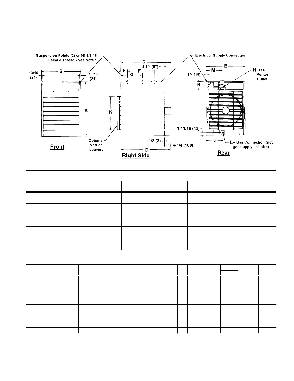
3. Dimensions
Fan-Type, Power-Vented Unit Heater
Dimensions (inches)
SizeABCDEFGHJKLMN
Nat Pro
29-25/32 13-9/16 27-1/16 31-7/ 16 5-27/32 14- 7/16 14-1/32 4 10-9/32 16 1/2 1/2 9-13/16 3
25
29-25/32 13-9/16 27-1/16 31-7/ 16 5-27/32 14- 7/16 14-1/32 4 10-9/32 16 1/2 1/2 9-13/16 3
50
29-25/32 15-9/16 27-1/16 31-7/ 16 5-27/32 14- 7/16 14-1/32 4 10-17/ 3 2 16 1/2 1/2 10-7/16 3
75
29-25/32 17-9/16 30-7/16 31-7/ 16 5-27/32 14- 7/16 14-1/32 4 12-29/ 3 2 16 1/2 1/2 10-7/16 3
100
29-25/32 23-5/16 30-7/16 31-7/ 16 5-27/32 14- 7/16 14-1/32 5 14-7/16 16 1/2 1/2 11-9/16 2-5/8
125
39-15/16 20-5/16 35-7/16 35-15/ 1 6 4-7/8 19-15/32 15-23/32 5 14-9/32 24 1/2 1/2 11-11/16 4- 1 9/32
165
39-15/16 23-5/16 36-3/16 35-15/ 1 6 4-7/8 19-15/32 15-23/32 5 14-13/32 24 1/2 1/2 11-11/16 4-19/ 32
200
39-15/16 28-13/ 1 6 36-3/16 35-15/1 6 4-7/8 19-15/32 15-23/32 5 12-11/ 32 24 1/2 1/2 11-11/16 4-19/ 32
250
39-15/16 28-13/ 1 6 36- 11/16 35-15/ 1 6 4-7/8 19-15/32 15-23/32 6 12-11/32 24 3/4 1/2 11-11/16 3-19/ 32
300
39-15/16 37-1/16 37-5/16 35-15/ 1 6 4-7/8 19-15/32 15-23/32 6 13 24 3/4 1/ 2 11-11/16 3-19/32
400
Dimensions (mm)
SizeABCDEFGHJKLMN
Nat Pro
25
50
75
100
125
165
200
250
300
400
756 344 687 799 148 367 356 102 261 406 13 13 249 76
756 344 687 799 148 367 356 102 261 406 13 13 249 76
756 395 687 799 148 367 356 102 267 406 13 13 265 76
756 446 773 799 148 367 356 102 328 406 13 13 265 76
756 592 773 799 148 367 356 127 367 406 13 13 294 67
1014 516 900 913 124 498 399 127 363 610 13 13 297 117
756 592 919 913 124 498 399 127 366 610 13 13 297 117
756 732 919 913 124 498 399 127 314 610 13 13 297 117
756 732 932 913 124 498 399 152 314 610 19 13 297 91
756 941 948 913 124 498 399 152 330 610 19 13 297 91
Suspension Notes: Use Dimension "G" for two-point suspension and "E" and "F" for four-
point suspension. (Two-point suspension is standard; four-point is optional. Four-point suspension is available either factory or field installed.)
Mfg P/N 98807 Rev 8, Page 3
Page 4
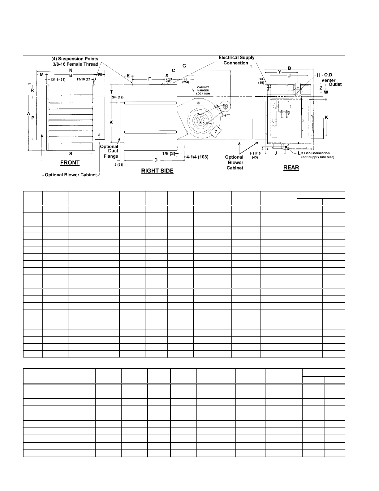
3. Dimensions (cont'd)
Blower-Type, Power-Vented Unit Heater
Dimensions (inches)
Size
25
50
75
100
125
165
200
250
300
400
Size
25
50
75
100
125
165
200
250
300
400
Dimensions (mm)
Size
25
50
75
100
125
165
200
250
300
400
Form 436, Page 4
ABCDEF
29-25/32 13-9/16 43-3/8 31-7/16 5-27/32 14-7/16 61-3/8 4 10-9/32 16 1/2 1/2
29-25/32 13-9/16 50 31-7/16 5-27/32 14 -7/16 61-3/8 4 10-9/32 16 1/2 1/2
29-25/32 15-9/16 50 31-7/16 5-27/32 14 -7/16 61-3/8 4 10-17/32 16 1/2 1/2
29-25/32 17-9/16 50 31-7/16 5-27/32 14 -7/16 61-3/8 4 12-29/32 16 1/2 1/2
29-25/32 23-5/16 47-1/2 31-7/16 5-27/32 14-7/16 65-29/32 5 14-7/16 16 1/2 1/2
39-15/16 20-5/16 61 35-15/16 4-7/8 19-15/32 76-1/8 5 14-9/32 24 1/2 1/2
39-15/16 23-5/16 66-1/2 35-15/16 4-7/8 19-15/32 76-1/8 5 14-13/32 24 1/2 1/2
39-15/16 28-13/16 66-1/2 35-15/16 4-7/8 19-15/32 76-1/8 5 12-11/32 24 1/2 1/2
39-15/16 28-13/16 66-1/2 35-15/16 4-7/8 19-15/32 76-1/8 6 12-11/32 24 3/4 1/2
39-15/16 37-1/16 66-1/2 35-15/16 4-7/8 19-15/32 76-1/8 6 13 24 3/4 1/2
MNPRST U W
3-23/32 20-15/16 17-3/4 5-1/4 10-3/4 8-7/16 14-3/4 6-3/16 31-7/32 9-13/16 3
3-23/32 20-15/16 17-3/4 5-1/4 10-3/4 8-7/16 14-3/4 6-3/16 31-7/32 9-13/16 3
2-23/32 20-15/16 17-3/4 5-1/4 12-3/4 8-7/16 14-3/4 6-3/16 31-7/32 10-7/16 3
1-23/32 20-15/16 17-3/4 5-1/4 14-3/4 8-7/16 14-3/4 6-3/16 31-7/32 10-7/16 3
1-11/32 20-15/16 17-3/4 5-1/4 20-1/2 8-7/16 20-1/2 6-3/16 35-3/4 11-9/16 2-5/8
2-27/32 25-15/16 25-1/4 7-1/4 17-1/2 11-7/16 20-1/2 7-15/16 36-11/16 11-11/1 6 4-19/32
1-11/32 25-15/16 25-1/4 7-1/4 20-1/2 11-7/16 20-1/2 7-15/16 36-11/16 11-11/1 6 4-19/32
5-29/32 40-9/16 25-1/4 7-1/4 26 11-7/16 26 7-15/16 36-11/16 11-11/16 4-19/32
5-29/32 40-9/16 25-1/4 7-1/4 26 11-7/16 26 7-15/16 36-11/16 11-11/16 3-19/32
6-25/32 50-9/16 25-1/4 7-1/4 34-1/4 11-7/16 34-1/4 7-15/16 36-11/16 11-11/16 3-19/32
ABCDEF
756 344 1102 799 148 367 1559 102 261 406 13 13
756 344 1270 799 148 367 1559 102 261 406 13 13
756 395 1270 799 148 367 1559 102 267 406 13 13
756 446 1270 799 148 367 1559 102 328 406 13 13
756 592 1207 799 148 367 1674 127 367 406 13 13
1014 516 1549 913 124 495 1934 127 363 610 13 13
1014 592 1689 913 124 495 1934 127 366 610 13 13
1014 732 1689 913 124 495 1934 127 314 610 13 13
1014 732 1689 913 124 495 1934 152 314 610 19 13
1014 914 1689 913 124 495 1934 152 330 610 19 13
Hanger
Hanger
GH J K L
XYZ
Nat Pro
Hanger
GH J K L
Nat Pro
Page 5
Size
25
50
75
100
125
165
200
250
300
400
MNPRST U W
94 532 48 1 133 273 214 375 157 793 249 76
94 532 48 1 133 273 214 375 157 793 249 76
69 532 48 1 133 324 214 375 157 793 265 76
44 532 48 1 133 375 214 375 157 793 265 76
34 532 48 1 133 521 214 521 157 908 294 67
72 659 64 1 184 445 291 521 202 932 297 11 7
34 659 64 1 184 521 291 521 202 932 297 11 7
150 1030 641 184 660 291 660 202 932 297 117
150 1030 641 184 660 291 660 202 932 297 91
172 1284 641 184 870 291 870 202 932 297 91
XYZ
Hanger
When equipped with optional blower cabinet.
When equipped with optional duct flange.
Dimension includes a 3/4" flange on the rear of the blower
cabinet.
NOTES
Use with 4-point suspension without blower cabinet. If
installing hanger kit Option CK19, suspension points
change; see Paragraph 8.
4. Uncrating and Preparation
This unit was test operated and inspected at the factory prior to crating and was in operating condition. If the heater has incurred any
damage in shipment, file a claim with the transporting agency.
Check the rating plate for the gas specifications and electrical characteristics of the heater to be sure that they are compatible with the
gas and electric supplies at the installation site. Read this booklet
and become familiar with the installation requirements of your particular heater. If you do not have knowledge of local requirements,
check with the local gas company or any other local agencies who
might have requirements concerning this installation. Before beginning, make preparations for necessary supplies, tools, and manpower.
Check to see if there are any field-installed options that need to be
assembled to the heater prior to installation. Each of the option packages includes a list of components and step-by-step instructions. For
a brief description of optional hanger kits, refer to Paragraph 8. For a
brief explanation of other frequently specified field-installed options,
see Paragraphs 25-31. After becoming familiar with the instructions,
assemble and install the options that are required for your heater.
If the heater was ordered with a vent cap shipped with the heater
(Option BT2), packaging depends on the size of the heater. Sizes 25
and 50 have the vent cap mounted on a shipping tube that is attached
to the venter housing. Remove the vent cap; remove and discard the
shipping tube. Sizes 100, 165, 200, 250, 300 and 400 have the vent
cap attached directly to the venter housing. Size 125 is shipped with
the vent cap mounted on the crate near the gas valve. Remove the
vent cap for field installation at the vent terminal.
Unless the crate bottom has been removed for option installation,
leave it attached until after the heater has been suspended. If the
crate bottom has been removed, the bottom of the heater must be
supported with plywood or appropriately placed boards. Without
adequate support, the bottom access panel could be damaged.
To protect the unit during shipping, the blower model has special
supports that must be removed before installation. Follow these instructions to remove:
oBlower Support Legs -- Remove the two blower support legs and
screws.
oMotor Shipping Block - Remove the wooden block located under
the motor bracket. Find the two rubber pads shipped in the instruction envelope. Place these pads on the ends of the motor
bracket bolts.
Use with 4-point suspension with blower cabinet.
Contactor is standard on Models 300 and 400; optional on other
sizes.
Contactor location with optional three phase motors on Sizes 50,
75, 100 and 125.
Deduct 6-5/8" on Sizes 50, 75, and 100 when equipped with
direct drive motor.
oMotor Shipping Plate -- Blower models that are equipped with motors
of 3/4 HP or less have a metal shipping plate attached between the
motor and the blower housing. Remove and discard the shipping plate.
Note: On units factory equipped with an optional belt guard, the belt
guard must be removed in order to reach the shipping plate.
5. Unit Heater Location
CAUTION: A void installing a unit heater in extremely
drafty areas. Extreme drafts can shorten the life of the
heat exchanger and/or cause safety problems.
For best results, the heater should be placed with certain rules in mind. In
general, a unit should be located from 8 to 12 feet above the floor. Units
should always be arranged to blow toward or along exposed wall surfaces, if possible. Where two or more units are installed in the same room,
a general scheme of air circulation should be maintained for best results.
Suspended heaters are most effective when located as close to the working zone as possible, and this fact should be kept in mind when determining the mounting heights to be used. However, care should be exercised
to avoid directing the discharged air directly on the room occupants.
Partitions, columns, counters, or other obstructions should be taken into
consideration when locating the unit heater so that a minimum quantity
of airflow will be deflected by such obstacles.
When units are located in the center of the space to be heated, the air
should be discharged toward the exposed walls. In large areas, units should
be located to discharge air along exposed walls with extra units provided
to discharge air in toward the center of the area.
At those points where infiltration of cold air is excessive, such as at entrance doors and shipping doors, it is desirable to locate the unit so that it
will discharge directly toward the source of cold air from a distance of 15
to 20 feet.
Units should not be installed closer than 18 inches from any wall.
CAUTION: Do not locate the heater where it may be
exposed to water spray, rain or dripping water.
6. Clearances & Combustion Air
Units must be installed so that the following clearances are provided for
combustion air space, service and inspection, and for proper spacing from
combustible construction.
Mfg P/N 98807 Rev 8, Page 5
Page 6
6. Clearances and Combustion
Air (cont'd)
Model Required Clearances (inches and mm)
Size Top Flue Sides Bottom Rear
Collector
25-400 6"(152) 6"(152) 18"(457) 12"(305) * 24" (610)**
* When supplied with optional downturn nozzle, bottom clearance is
42"(1067mm). For service purposes, on standard units, bottom clearance exceeding minimum (12" or 305mm) is not required but may
be desirable.
** For servicing purposes only, rear must remain full open.
All fuel-burning equipment must be supplied with the air that enters
into the combustion process and is then vented to the outdoors. Sufficient air must enter the equipment location to replace that exhausted
through the heater vent system. In the past, the infiltration of outside
air assumed in heat loss calculations (one air change per hour) was
assumed to be sufficient. However, current construction methods utilizing more insulation, vapor barriers, tighter fitting and gasketed doors
and windows or weather-stripping, and mechanical exhaust fans may
now require the introduction of outside air through wall openings or
ducts.
The requirements for combustion and ventilation air depend upon
whether the unit is located in a confined or unconfined space. An "unconfined space" is defined as a space whose volume is not less than 50
cubic feet per 1000 BTUH of the installed appliance. Under all condi-
tions, enough air must be provided to ensure there will not be a negative pressure condition within the equipment room or space. For specific requirements for confined space installation, see Paragraph 7.
W ARNING: These power-vented unit heaters ar e
designed to take combustion air from the space
in which the unit is installed and are not designed
for connection to outside combustion air intake
ducts. Connecting outside air ducts voids the
warranty and could cause hazardous operation.
See Hazard Levels, Page 2.
7. Combustion Air Requirements
for a Heater Located in a
Confined Space
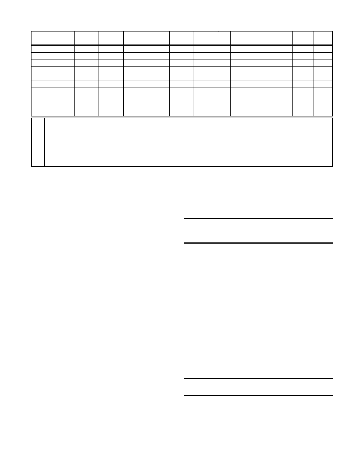
Do not install a unit in a confined space without providing wall openings leading to and from the space. Provide openings near the floor
and ceiling for ventilation and air for combustion as shown in Figure
1, depending on the combustion air source as noted in Items 1, 2, and
3 below the illustration.
Figure 1 Confined Space: A
space whose volume is
less than 50 cubic feet
per 1000 BTUH of the
installed appliance
input rating
Add total BTUH of all appliances in the confined space and divide by
figures below for square inch free area size of each (top and bottom)
opening.
1. Air from inside the building -- openings 1 square inch free area per
1000 BTUH. Never less than 100 square inches free area for each opening. See (1) in Figure 1.
2. Air from outside through duct -- openings 1 square inch free area
per 2000 BTUH. See (2) in Figure 1.
3. Air direct from outside -- openings 1 square inch free area per 4000
BTUH. See (3) in Figure 1.
NOTE: For further details on supplying combustion air to a confined
space, see the National Fuel Gas Code ANSI Z223.1a (latest edition ).
8. Suspending the Heater
Before suspending the heater, check the supporting structure to be used
to verify that it has sufficient load-carrying capacity to support the weight
of the unit.
Net Weight (lbs and kg)
Model Size
Type 25 50 75 100 125 165 200 250 300 400
Fan lbs 76 83 92 101 132 154 175 209 226 281
kg 34 38 42 46 60 70 79 95 103 127
Blower lbs 97 104 118 130 180 206 240 278 301 395
kg 44 47 54 59 82 93 109 126 137 179
NOTE: If the installation includes an optional stepdown transformer
kit (Option CF or CG), the stepdown transformer bracket is part of the
heater suspension and must be installed prior to hanging the heater.
Follow the instructions on the installation sheet included with the option kit.
A fan-type unit heater is equipped with standard two-point suspen-
sion. A 3/8-16 threaded hanger bracket assembly is located on each
side of the heater. If a fan-type unit has been ordered with optional,
factory-installed, four-point suspension (Option BJ6), it will have two
threaded hanger brackets on each side.
A blower-type heater is equipped with standard four-point suspen-
sion. Two 3/8-16 threaded hanger bracket assemblies are located on
each side of the unit. Each hanger bracket assembly is designed for
threaded rod attachment.
For both "standard" and "optional" suspension point dimensions, see
Dimension Tables in Paragraph 3. (Note: If installing Option CK19
hanger kit, suspension points change; see Figure 4B.)
WARNING: Suspend the heater only from the
threaded hanger brackets. Do not suspend from
the heater side panel.
When the heater is lifted for suspension, the bottom must be protected.
If the wooden crate bottom has been removed, the bottom of the heater
will have to be supported with plywood or other appropriately placed
material. If the bottom is not supported, the bottom access panel could
be damaged. Also, when lifting a blower unit, support the blower and
motor to prevent the unit from tipping.
All blower models have legs that support the blower assembly during
shipping. After
the unit is suspended, these
legs should be
removed.
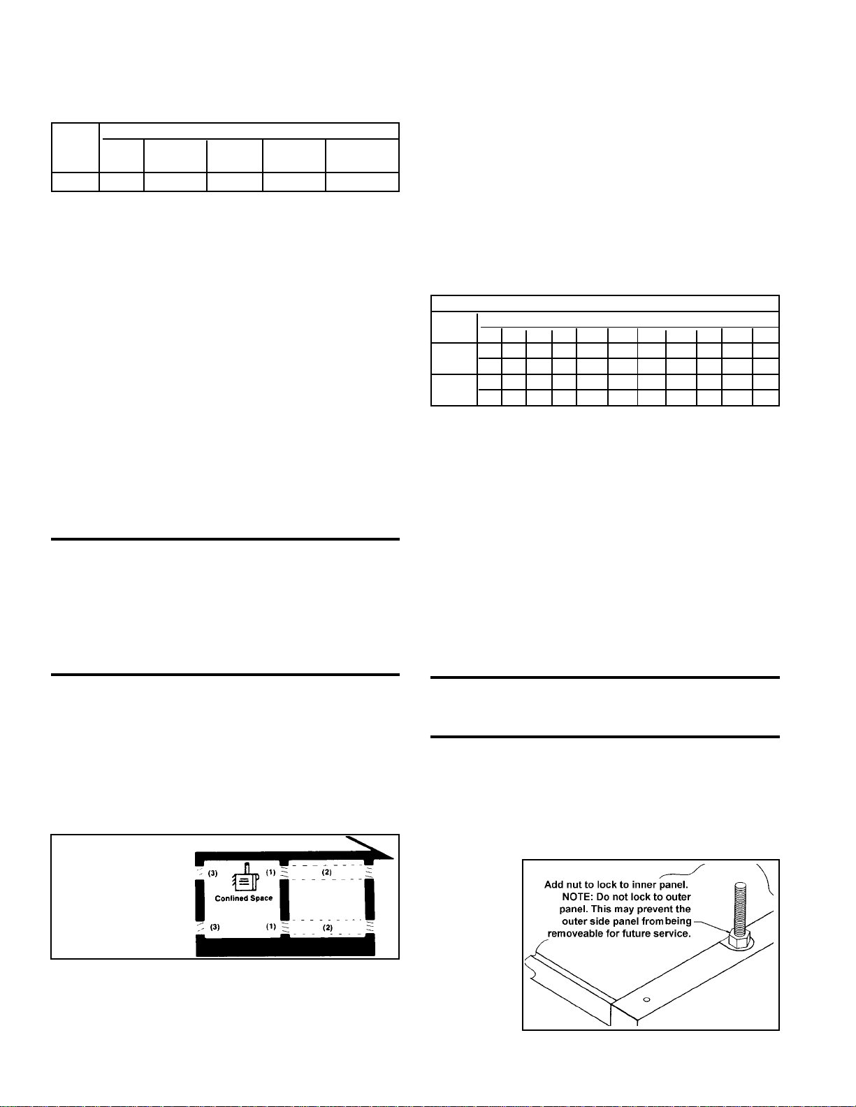
Be sure that the
threaded hanger
rods are locked
to the heater as
shown in Figure
2.
Figure 2 -
Suspension
Form 436, Page 6
Page 7
WARNING: Unit must be level for proper
operation. Do not place or add additional weight
to the suspended heater. See Hazard Levels, page
2.
If an optional downturn air nozzle is used, the unit must be suspended from four points to ensure level suspension. Two hanger
brackets are included in the downturn option package and must
be field-installed on fan-type units with standard two-point suspension. For additional information, refer to Paragraph 26 and
the instructions that are furnished with the option package.
When blower-type units are equipped with an optional blower/
filter cabinet, there are two suspension points on the blower cabinet hanger bar. Suspend a unit equipped with a blower/filter cabinet from four points, using the two heater hanger bracket assemblies closest to the front of the heater and the two suspension
points on the blower/filter cabinet.
If one of the optional, field-installed hanger kits has been ordered
for your heater, it will have been shipped separately . Each option
package includes a list of components and complete, step-by-step
assembly instructions.
Optional, Field-Installed Hanger Kits:
1) Four-Point Suspension (fan models only) - Option CK7
This option kit is designed to convert a fan-type heater from standard two-point suspension to four-point suspension. The kit contains two additional hanger brackets.
2) Two-Point Swivel Connectors (fan models only) - Option
CK8 (See Figure 3.)
The purpose of this option kit is to adapt the standard hanger
bracket so that the heater can be suspended from 1", threaded,
stationary pipe. The swivel connector screws "into" the threaded
hanger bracket on the heater and "onto" the 1" threaded pipe used
for hanging the heater. The kit includes two swivel hanger connector assemblies and two lock washers.
4) Four-Point Swivel Connectors - Option CK10 (See Figure 4A)
This option package is used on a heater that is already equipped with fourpoint suspension to adapt it for suspension from four 1", threaded, stationary pipes. The kit includes four swivel hanger connector assemblies and
four lock washers.
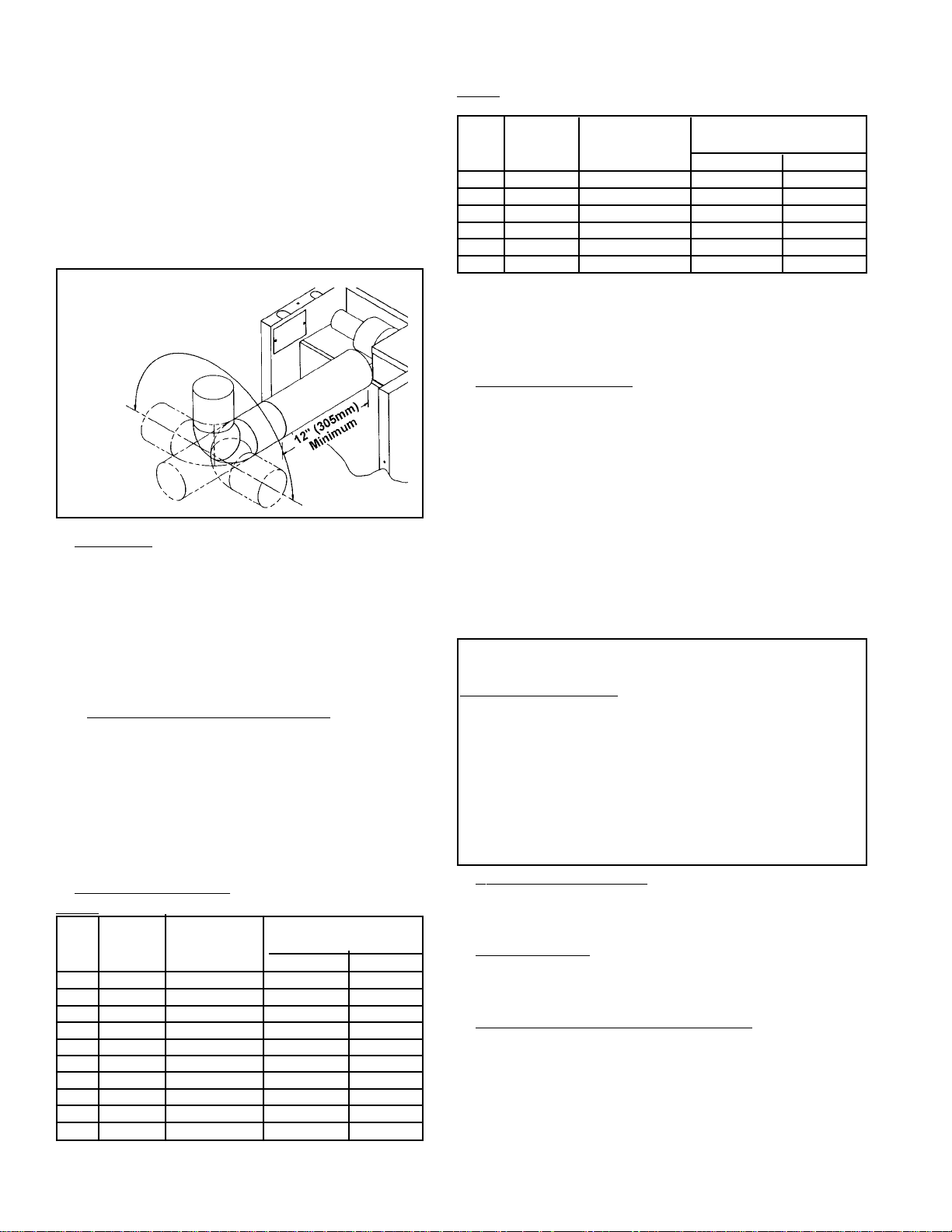
5) Special Four-Point Suspension with Nearly Equal Loading (applies
to blower models only) - Option CK19
This suspension option is designed for special applications when a suspension system is needed that has nearly equal loading at all four suspension
points. Use this option in installations with spring isolation designed for
seismic protection or when threaded rod hangers are longer than twelve
inches.
Suspension points change with the addition of hanger kit Option CK19; see
Figure 4B.
Figure 4B - Suspension Dimensions (inches and mm) for
Model BE Heater with Hanger Kit Option CK19
Size A B
25-50 11-7/8 (302) 9-1/8 (232)
75 13-7/8 (352) 11-1/8 (283)
100 15-7/8 (403) 13-1/8 (333)
125 21-5/8 (549) 18-7/8 (479)
165 18-5/8 (473) 15-7/8 (403)
200 21-5/8 (549) 18-7/8 (479)
250 27-1/8 (689) 24-3/8 (618)
300 27-1/8 (689) 24-3/8 (618)
400 35-3/8 (897) 32-5/8 (829)
Figure 3 - TwoPoint Suspension
with Swivel
Connections
(fan models
only)
3) Four-Point with Swivel Connectors (fan-models only) Option CK9 (See Figure 4A)
This option package is designed to convert a fan-type heater from
standard two-point suspension to four-point suspension with
swivel connectors. By installing this kit the standard fan-type heater
can be hung from four 1", threaded, stationary pipes. The kit includes two hanger bracket assemblies, four swivel hanger connector assemblies and four lock washers.
Figure 4A - Four-Point Suspension with Swivel
Connections (Applies to both fan
and blower models)
9. Venting
These power-vented unit heaters are designed to operate safely and efficiently with either a horizontal or vertical vent. (Horizontal vent run is recommended for maximum fuel savings.)
WARNING: Units installed in multiples require
individual vent pipe runs and vent caps. Manifolding
of vent runs is not permitted due to possible
recirculation of combustion products into the
building and possible back pressure effects on the
combustion air proving switch.
Specific Venting Requirements (read all before
installing)
1. Venter (Flue) Outlet
Venter Outlet Size:
Model Size Outlet Diameter
25-100 4" (102 mm)
125-250 5" (127 mm)
300-400 6" (152 mm)
Mfg P/N 98807 Rev 8, Page 7
Page 8
9. Venting (cont'd)
Venter Outlet Attachment Requirements:
• If the pipe used in the vent run is larger than the diameter of the
venter outlet (See Vent Length Table 2), make the transition at
the venter outlet.
• A minimum of 12" of straight pipe is required at the venter
outlet (or transition fitting) before installing an elbow in the
vent system. An elbow should never be attached directly to the
venter. An elbow attached to the straight pipe can be in any
position at or above horizontal. See Figure 5.
Figure 5 - Alternate Vent
Directions (vent in any
position above horizontal;
minimum of 12" of straight
pipe
required
before
an
elbow)
2. Vent Pipe
If installed with a horizontal vent run, use either vent pipe approved
for a Category III heater or appropriately sealed 26-gauge galvanized steel or equivalent single-wall pipe.
If at least half of the equivalent length of the vent system is vertical, vent pipe approved for a Category I heater may be used. Singlewall pipe or double-wall (Type B) vent pipe are suitable for use
with a Category I heater.
Use only one of the flue pipe diameters listed in the Vent Length
Tables for the furnace size being installed.
2A. Vent Pipe Diameter Reduction
If at least half of the equivalent length of the vent system is vertical, the vent pipe diameter may be reduced one inch from the standard diameter listed in Vent Length Table 1. Only single-wall pipe
is suitable for use when reducing the pipe diameter. A taper-type
reducer must be used. The maximum allowable vent length remains
the same. If required, double wall pipe may be used at the terminal
end as shown in Figure 6. (Use the equivalent length for elbows as
shown in Vent Length Table 1 for the standard vent pipe diameter.
All elbows used in the vent system must be considered.)
3. Vent Length Tables
Table 1: Maximum Permissible Vent Lengths
V ent Pipe Maximum Equivalent Straight
Model Diameter Vent Length* Length** - ft (m)
-" (mm) - ft (m) 90o Elbows 45o Elbows
25 4"(102) 30 ft (9.1 m) 3.5' (1 m) 1.8' (.5 m)
50 4"(102) 40 ft (12.2 m) 5' (1.5 m) 2.5' (.8 m)
75 4"(102) 50 ft (15.2 m) 7' (2.1 m) 3.5' (1.1 m)
100 4"(102) 50 ft (15.2 m) 7' (2.1 m) 3.5' (1.1 m)
125 5"(127) 50 ft (15.2 m) 5' (1.5 m) .5' (.8 m)
165 5"(127) 50 ft (15.2 m) 9' (2.7 m) 4.5' (1.4 m)
200 5"(127) 50 ft (15.2 m) 8' (2.4 m) 4.0' (1.2 m)
250 5"(127) 50 ft (15.2 m) 10' (3.0 m) 5' (1.5 m)
300 6"(152) 50 ft (15.2 m) 11' (3.4 m) 5.5' (1.7 m)
400 6"(152) 50 ft (15.2 m) 15' (4.6 m) 7.5' (2.3 m)
Form 436, Page 8
T able 2: Optional Maximum Permissible Vent Lengths
(Requires an increase in vent pipe diameter.)
V ent Pipe Maximum Equivalent Straight
Model Diameter Vent Length* Length** - ft (m)
- " (mm) - ft (m) 90o Elbows 45o Elbows
100 5" (127) 60 ft (18.3 m) 8' (2.4 m) 4.0' (1.2 m)
165 6" (152) 60 ft (18.3 m) 10' (3.0 m) 5.0' (1.5 m)
200 6" (152) 60 ft (18.3 m) 12' (3.7 m) 6.0' (1.8 m)
250 6" (152) 70 ft (21.3 m) 8' (2.4 m) 4.0' (1.2 m)
300 7" (178) 70 ft (21.3 m) 13' (4.0) 6.5' (2.0 m)
400 7" (178) 90 ft (27.4 m) 14' (4.3) 7.0' (2.1)
*Note 1: If the system contains all vertical pipe or a combination of horizontal
and vertical vent pipe, the Maximum Permissible Vent Length shown in Tables 1
and 2 may be increased one foot for each foot vertical rise up to a maximum
increase of 10 feet for model sizes 25 thru 100 and up to 20 feet for model sizes
125 thru 400.
**Reduce the maximum vent length by the amount indicated for each elbow.
4. Vent System Joints
Vent system joints depend on the installation and the type of pipe being
used.
• If using single wall, 26-gauge or heavier galvanized pipe, secure slipfit connections using sheet metal screws or rivets. Seal pipe joints either with tape suitable for 550
o
F (such as Option FA1, P/N 98266) or
high-temperature silicone sealant.
• If using Category III vent pipe, follow pipe manufacturer's instructions
for joining pipe sections. When attaching Category III pipe to the venter outlet or the vent cap, make secure, sealed joints following a procedure that best suits the style of Category III pipe being used.
• If using double-wall (Type B) vent pipe (allowed only if 1/2 of the
equivalent vent length is vertical), follow pipe manufacturer's instructions for joining pipe sections. For joining double-wall pipe to the venter outlet collar, single-wall pipe, and/or the vent cap, follow the instructions below.
Instructions for attaching double-wall (Type B) vent pipe to the venter outlet, a single-wall pipe run, or to the vent cap (use these instructions for either full length double-wall or terminal only):
Hardware and Sealant Required: 3/4" long sheetmetal screws; and a tube of RTV
1) Look for the "flow" arrow on the vent pipe; attach according to the arrow.
Slide the pipe so that the venter outlet, the single-wall pipe, or the vent cap is
inside the double-wall pipe.
2) Drill a hole through the pipe into the outlet collar, the single-wall pipe, or the
vent cap. (Hole should be slightly smaller than the sheet metal screw being used.)
Using a 3/4" long sheet metal screw, attach the pipe. Do not overtighten. Repeat,
drilling and inserting two additional screws evenly spaced (120o apart) around
the pipe.
3) Use RTV to seal any gaps. If there is an annular opening, run a large bead of
RTV in the opening. The bead of RTV must be large enough to seal the opening,
but it is not necessary to fill the full volume of the annular area.
5. Vent System Support
Support lateral runs every six feet, using a non-combustible material such
as strap steel or chain. Do not rely on the heater for support of either horizontal or vertical vent pipe
6. Condensation
Single wall vent pipe exposed to cold air or run through unheated areas
must be insulated. Where extreme conditions are anticipated, install a means
of condensate disposal.
7. Vent Terminal (Pipe and Vent Cap)
The vent system must be terminated with a suitable vent cap that is the
same size as the vent run.
Heaters installed in Canada must be equipped with the vent cap sup-
plied as optional equipment by the heater manufacturer (Option CC1 or
Option BT2). Heaters installed in the United States must be equipped
with the heater manufacturer's vent cap, a Type L Breidert Air-x-hauster
vent cap, or equivalent. Use of a vent cap supplied by the pipe manufac-
®
Page 9
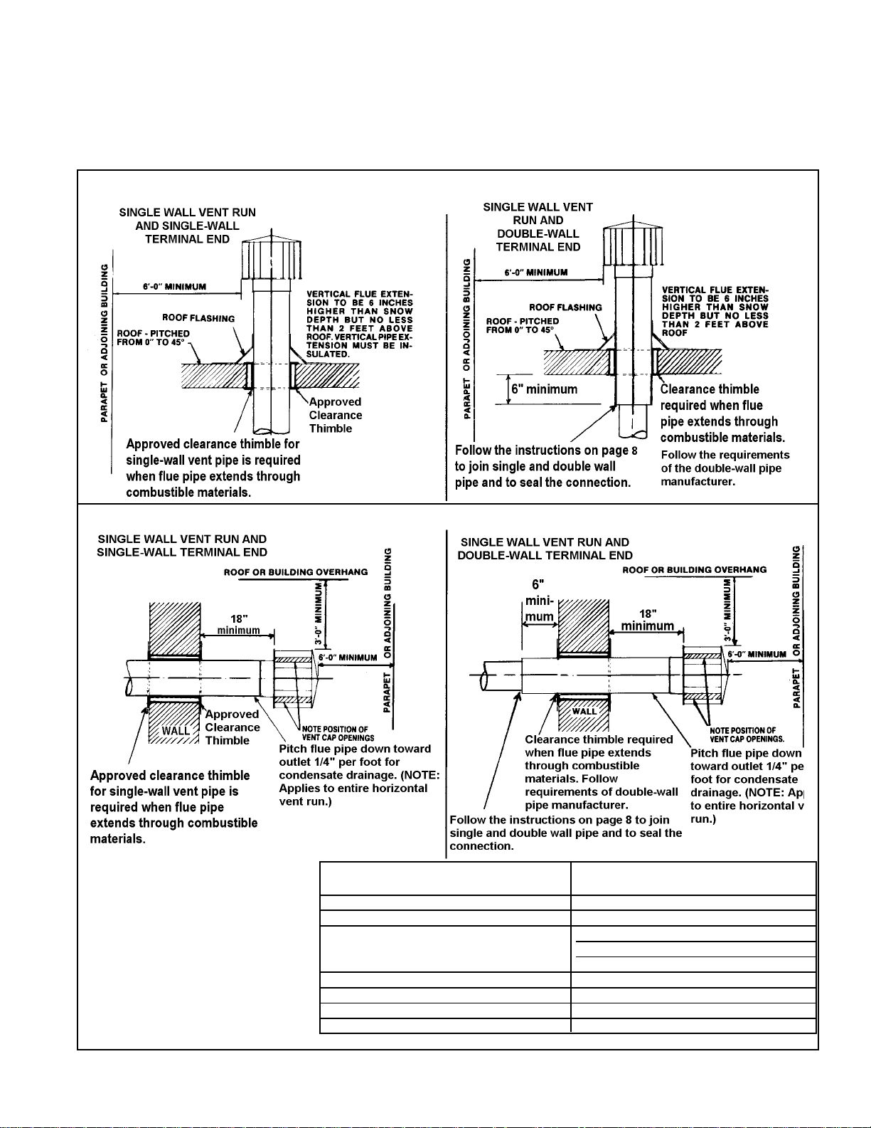
turer is not permitted; the vent cap must be the type approved for use
with this heater. A different style vent cap could cause nuisance problems or unsafe conditions.
See the illustrations in Figures 6 and 7 for requirements of both vertical and horizontal vent termination. The vent terminal section may be
Figure 6 - Vertical Vent Terminals
either single-wall or double-wall (Type B) vent pipe. If double-wall
pipe is used in the vent terminal with a single-wall vent run, follow the
instructions in No. 4, V ent System Joints, to attach the vent cap and to
connect the double-wall pipe to the single-wall vent pipe run.
Figure 7 - Horizontal Vent Terminals
Horizontal V ent Terminal Clearances:
The location of the termination of the horizontal vent system must be in accordance with
National Fuel Gas Code Z223.1. Required
minimum clearances are listed on the right.
Products of combustion can cause discoloration of some building finishes and deterioration of masonry materials. Applying a clear
silicone sealant that is normally used to protect concrete driveways can protect masonry
materials. If discoloration is an esthetic problem, relocate the vent or install a vertical vent.
Structure Minimum Clearances for V ent Termination
Location (all directions unless specified)
Forced air inlet within 10 ft (3.1m) 3 ft (0.9m) above
Combustion air inlet of another appliance 6 ft (1.8m)
Door, window, or gravity air inlet 4 ft (1.2m) horizontally
(any building opening) 4 ft (1.2m) below
3 ft (0.9m) above
Electric meter, gas meter * and relief equipment 4 ft (1.2m) horizontally
Gas regulator * 3 ft (0.9m)
Adjoining building or parapet 6 ft (1.8m)
Grade (ground level) 7 ft (2.1m) above
*Do not terminate the vent directly above a gas meter or service regulator.
Mfg P/N 98807 Rev 8, Page 9
Page 10

10. Gas Piping and Pressures
WARNING
This appliance is equipped for a maximum gas
supply pressure of 1/2 pound, 8 ounces, or 14
inches water column. Supply pressure higher
than 1/2 pound requires installation of an
additional service regulator external to the unit.
PRESSURE TESTING SUPPLY PIPING
Test Pressures Above 1/2 PSI: Disconnect the heater and manual
valve from the gas supply line which is to be tested. Cap or
plug the supply line.
Test Pressures Below 1/2 PSI: Befor e testing, close the manual
valve on the heater.
All piping must be in accordance with requirements outlined in the
National Fuel Gas Code ANSI/Z223.1a (latest edition), published by
the American Gas Association or CAN/CGA-B149.1 and B149.2, published by the Canadian Gas Association (See Paragraph 1). Gas supply
piping installation should conform with good practice and with local
codes.
Unit heaters for natural gas are orificed for operation with gas having a
heating value of 1000 (+ or - 50) BTUH per cubic ft. If the gas at the
installation does not meet this specification, consult the factory for
proper orificing.
Pipe joint compounds (pipe dope) shall be resistant to the action of
liquefied petroleum gas or any other chemical constituents of the
gas being supplied.
Install a ground joint union and manual shut-off valve upstream of the
unit control system, as shown in Figure 8. The 1/8" plugged tapping in
the shut-off valve provides connection for supply line pressure test
gauge. The National Fuel Gas Code requires the installation of a trap
with a minimum 3" drip leg. Local codes may require a minimum drip
leg longer than 3" (typically 6").
Gas connection sizes are included in the Dimensional Tables in Paragraph 3. After all connections are made, disconnect the pilot supply at
the control valve and bleed the system of air. Reconnect the pilot line
and leak-test all connections by brushing on a soap solution.
Sizing a Gas Supply Line
Ca pa c it y of P i pin g
Cubic Feet per Hour based on 0.3" w .c. Pressure Drop
Sp ecific Grav ity fo r N at ural G as -- 0.6 (N atu ral G as -- 10 0 0 B T U /C u bic Ft )
Specific Gravity for Propane G as -- 1.6 (P ropane Gas -- 2550 BT U /Cubic Ft)
Length Diameter of Pipe
of 1/2" 3/4" 1" 1-1/4" 1-1/2" 2"
Pipe Natu ral Propane N atural Pro p ane Natural Pro pane Natural Propane N atural Pro p ane Natural Pro pane
20' 92 56 190 116 350 214 730 445 1100 671 2100 1281
30' 73 45 152 93 285 174 590 360 890 543 1650 1007
40' 63 38 130 79 245 149 500 305 760 464 1450 885
50' 56 34 115 70 215 131 440 268 670 409 1270 775
60' 50 31 105 64 195 119 400 244 610 372 1105 674
70' 46 28 96 59 180 110 370 226 560 342 1050 641
80' 43 26 90 55 170 104 350 214 530 323 990 604
90' 40 24 84 51 160 98 320 195 490 299 930 567
100' 38 23 79 48 150 92 305 186 460 281 870 531
125' 34 21 72 44 130 79 275 168 410 250 780 476
150' 31 19 64 39 120 73 250 153 380 232 710 433
175' 28 17 59 36 110 67 225 137 350 214 650 397
200' 26 16 55 34 100 61 210 128 320 195 610 372
N o t e: W h e n s iz in g s u p p ly lin e s , c o n s id e r p o s s ib ilit ie s o f f u t u r e exp a n s io n a n d in c re a s ed r eq u ir e m e n t s .
Refer to National F uel G as Code for additional information on line siz ing.
Form 436, Page 10
Figure 8 - Supply
Piping Connection
WARNING: All components of a gas supply
system must be leak tested prior to placing
equipment in service. NEVER TEST FOR
LEAKS WITH AN OPEN FLAME. Failure to
comply could result in personal injury , property
damage or death.
Manifold or Orifice Pressure Settings
Measuring manifold gas pressure cannot be done until the heater is in
operation. It is included in the steps of the "Check-Test-Start" proce-
dure in Paragraph 24. The following warnings and instructions apply.
WARNING: Manifold gas pressure must never
exceed 3.5" w.c. for natural gas and 10" w.c. for
propane gas.
For Natural Gas: Manifold gas pressure is regulated by the combina-
tion valve to 3.5" w.c. Inlet pressure to the valve must be a minimum of
5" w.c. or as noted on the rating plate and a maximum of 14" w.c.
For Propane Gas: Manifold gas pressure is regulated by the combination valve to 10" w.c. Inlet pressure to the valve must be a minimum of
11" w.c. and a maximum of 14" w.c.
Page 11

Before attempting to measure or adjust manifold gas pressure,
the inlet (supply) pressure must be within the specified range for
the gas being used both when the heater is in operation and on
standby. Incorrect inlet pressure could cause excessive manifold
gas pressure immediately or at some future time.
Instructions to Check Manifold Pressure:
1) With the manual valve (on the combination valve) positioned
to prevent flow to the main burners, connect a manometer to
the 1/8" pipe outlet pressure tap in the valve. NOTE: A manometer (fluid-filled gauge) is recommended rather than a
spring type gauge due to the difficulty of maintaining calibration of a
spring type gauge.
2) Open the valve and operate the heater. Measure the gas pressure to the
manifold. Normally adjustments should not be necessary to the factory
preset regulator.
If adjustment is necessary, set pressure to correct settings by turning the regulator screw IN (clockwise) to increase pressure. Turn regulator screw OUT
(counterclockwise) to decrease pressure.
Consult the valve manufacturer's literature provided with the heater for more
detailed information.
11. Electrical Supply and Connections
All electrical wiring and connections, including electrical grounding MUST be made in accordance with the National Electric
Code ANSI/NFP A No. 70 (latest edition) or, in Canada, the Canadian Electrical Code, Part I-C.S.A. Standard C22.1. In addition, the installer should be aware of any local ordinances or gas
company requirements that might apply.
Check the rating plate on the heater for the supply voltage and
current requirements. A separate line voltage supply with fused
disconnect switch should be run directly from the main electrical panel to the heater. All external wiring must be within approved conduit and have a minimum temperature rise of 60
Conduit from the disconnect switch must be run so as not to
interfere with the service panels of the heater.
The electrical supply connects at the top back of the heater in the
left corner (left when facing the back of the heater). A threaded
hole is provided for a standard 1/2" electrical fitting.
The wiring access panel is easily removed for field connections.
Consult the wiring diagram supplied with your heater. Replace
the panel after the wiring connections are made.
If the heater has field-installed options that require electrical connections, consult the instruction sheet and wiring diagram supplied in the option package.
A fan-type heater may be equipped with a built-in fused disconnect switch (Option AI-1). If the heater is equipped with a builtin disconnect switch, a two-position toggle (on/off) switch is
located near the electrical supply access panel (See Figures 9A
and 9B). This switch may be used to disconnect the power when
servicing the heater other than in the supply junction box.
Specific wiring diagrams that include standard and factory-installed options are included with the heater. Check the wiring
diagram to identify optional equipment.
o
C.
Field Wiring
from Disconnect
in Conduit
Threaded
Hole for
Standard 1/2"
Fitting
Note: Fan-type
heaters with optional
built-in disconnect
switch, have an on/off
switch located near
the electrical supply
access panel.
Remove
Access
Panel to
make
connections
Figure 9A - Electrical
Connections
WARNINGS: On a heater with
a unit disconnect switch (Option
AI-1), if the power is turned off
at the switch, the supply lead in
the electrical supply junction
box (Figure 9A) remains
energized. If service is to be
done in the supply junction box,
turn off the power at the remote
disconnect switch.
If you turn off the power supply ,
turn off the gas.
The operating sequence of the heater can be
found on the heater wiring diagram and is published in Paragraph 24, Check Installation and
Start-Up. Typical wiring diagrams ar e on the
next four pages, showing standard singlestage heating with spark pilot with and without lockout.
CAUTION: If any of the original wire as
supplied with the appliance must be replaced, it must be replaced with
wiring material having a temperature rating of at least 105
limit control and sensor lead wires which must be 150oC. See Hazard
Levels, page 2.
12. Thermostat and Thermostat
Connections
A thermostat is not standard equipment but is an installation requirement.
Use either an optional thermostat available with the heater or a field-supplied
thermostat. Install according to the thermostat manufacturer's instructions.
Make sure that the heat anticipator setting on the thermostat is in accordance
with the amperage value noted on the
wiring diagram of your heater.
Terminal Strip Connections - The
standard heater is equipped with a twoscrew terminal connector strip (See Figure 10) for easy connection to the low
voltage controls (24V). When factoryinstalled options require two-stage
thermostat control, the heater is
equipped with a SP-ST relay and a
four-screw terminal connector strip
(See Figure 11).
If your heater requires field installation of the four-screw terminal
strip and the relay, follow the instructions packaged with the relay
or thermostat option.
Figure 9B
If equipped
with unitmounted
disconnect
switch, on/
off toggle
switch is
near access
panel to
electrical
supply
junction
box.
Circuit
breaker
button for
Option AI-1
unitmounted
disconnect
switch
o
C, except for
Figure 10 -
Two Screw
Terminal
Connector
Strip for
24-volt
Wiring
Figure 11 -
Four Screw
Terminal
Connector
Strip for 24V olt Wiring
(Paragraph 12 continued on page 16.)
Mfg P/N 98807 Rev 8, Page 11
Page 12

TYPICAL WIRING DIAGRAMS -- Pages 12 - 15
Field Control Wiring Length and Gauge
T otal W ire Distance from MinimumRecommended
Length Unit to Control Wire Gauge
150' (45.7 m) 75' (22.9 m) #18 gauge
250' (76.2 m) 125' (38.1 m) #16 gauge
350' (106.7 m) 175' (53.3 m) #14 gauge
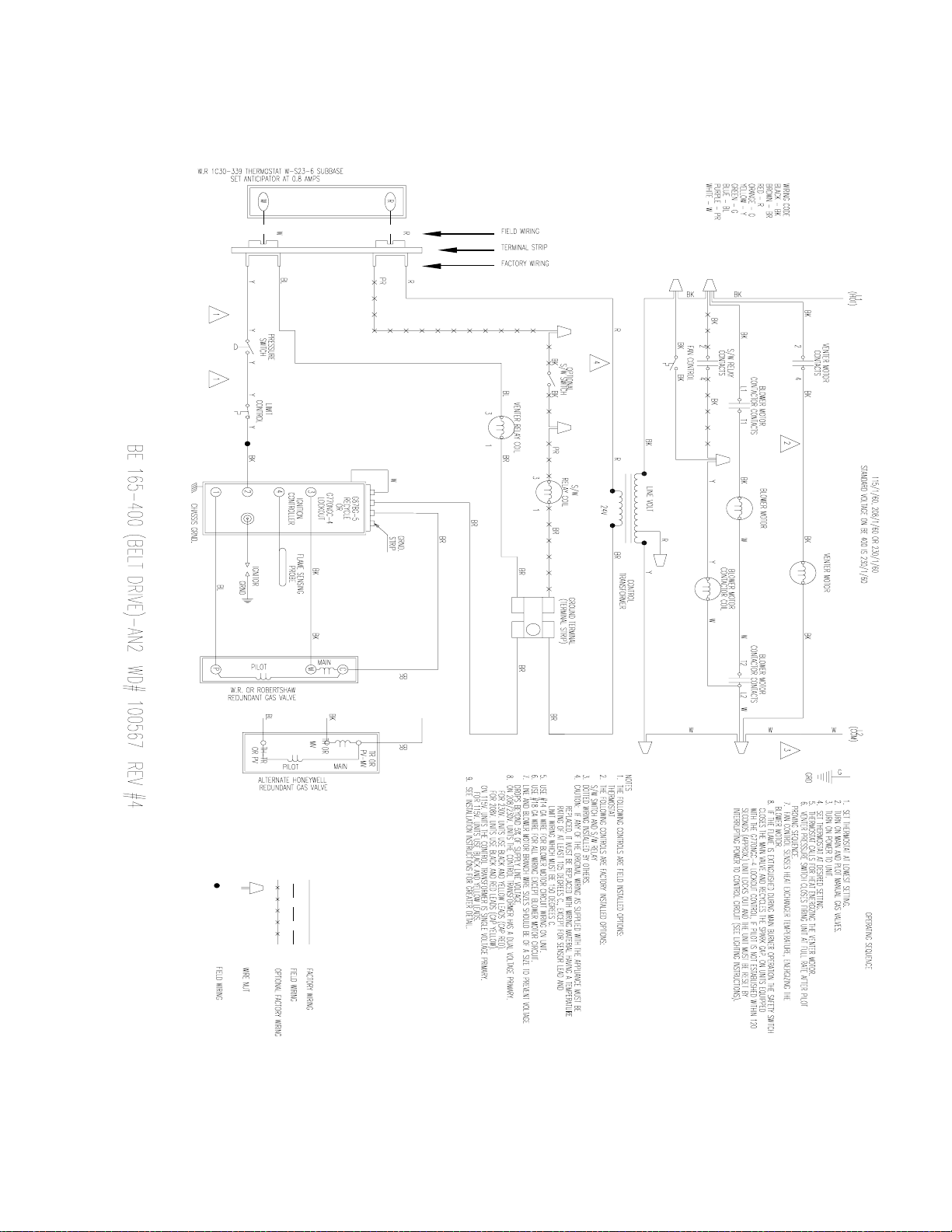
Fan-Type, Power-Vented Model
with Intermittent Spark Pilot,
Single-Stage Heating,
Natural or Propane
OPERATING SEQUENCE
1. SET THERMOSTAT AT LOWEST SETTING.
2. TURN ON MAIN AND PLOT MANUAL GAS VALVES.
3. TURN ON POWER TO UNIT.
4. SET THERMOSTAT AT DESIRED SETTING.
5. THERMOSTAT CALLS FOR HEAT ENERGIZING THE VENTER MOTOR.
6. VENTER PRESSURE SWITCH CLOSES FIRING UNIT AT FULL RATE AFTER PILOT
PROVING SEQUENCE.
7. FAN CONTROL SENSES HEAT EXCHANGER TEMPERATURE, ENERGIZING THE
FAN MOTOR.
8. IF THE FLAME IS EXTINGUISHED DURING MAIN BURNER OPERATION THE SAFETY SWITCH
CLOSES THE MAIN VALVE AND RECYCLES THE SPARK GAP. ON UNITS EQUIPPED
WITH THE G77ONGC-4 LOCKOUT CONTROL, IF PILOT IS NOT ESTABLISHED WITHIN 120
SECONDS (APPROX.) UNIT LOCKS OUT AND THE UNIT MUST BE RESET BY
INTERRUPTING POWER TO CONTROL CIRCUIT (SEE LIGHTING INSTRUCTIONS).
NOTES
1. THE FOLLOWING CONTROLS ARE FIELD INSTALLED OPTIONS:
THERMOSTAT
2. THE FOLLOWING CONTROLS ARE FACTORY INSTALLED OPTIONS:
S/W SWITCH
3. DOTTED WIRING INSTALLED BY OTHERS.
4. CAUTION: IF ANY OF THE ORIGINAL WIRING AS SUPPLIED WITH THE APPLIANCE MUST BE
REPLACED, IT MUST BE REPLACED WITH WIRING MATERIAL HAVING A TEMPERATURE
RATING OF AT LEAST 105 DEGREES C., EXCEPT FOR SENSOR LEAD AND
LIMIT WIRING WHICH MUST BE 150 DEGREES C.
5. USE #18 GA WIRE FOR ALL WIRING EXCEPT FAN MOTOR CIRCUIT.
6. LINE AND FAN MOTOR BRANCH WIRE SIZES SHOULD BE OF A SIZE TO PREVENT VOLTAGE
DROPS BEYOND 5% OF SUPPLY LINE VOLTAGE.
7. ON 230V. UNITS THE CONTROL TRANSFORMER HAS A DUAL VOLTAGE PRIMARY.
FOR 230V. UNITS USE BLACK AND YELLOW LEADS (CAP RED).
FOR 208V. UNITS USE BLACK AND RED LEADS (CAP YELLOW).
ON 115V. UNITS THE CONTROL TRANSFORMER IS A SINGLE VOLTAGE PRIMARY.
FOR 115V. UNITS USE BLACK AND YELLOW LEADS.
8. SEE INSTALLATION INSTRUCTIONS FOR GREATER DETAIL.
R
W
SET ANTICIPATOR AT 0.8 AMPS
W.R 1C30-339 THERMOSTAT W-S23-6 SUBBASE
WIRING CODE
BLACK - BK
BROWN - BR
RED - R
ORANGE - O
YELLOW - Y
GREEN - G
BLUE - BL
PURPLE - PR
WHITE - W
L1
(HOT)
VENTER RELAY
CONTACTS
BK BK
2 4
OPTIONAL
S/W SWITCH
BK BK
BK BK
FAN CONTROL
BK
BK
R
8
VENTER RELAY COIL
BL BR
FIELD WIRING
TERMINAL STRIP
FACTORY WIRING
R
R
BL
W
PRESSURE
SWITCH
CONTROL
Y YYY
5 5
FE 25-400 OPT. AH2/AH3 WD #97302 REV #8
31
LIMIT
6
BK
Y
115/1/60, 208/1/60 OR 230/1/60
VENTER MOTOR
BK
BK
R
LINE VOLT
R
BR
24V
BR
BR
5
GRND.
W
STRIP
G67BG-5
RECYCLE
OR
G770NGC-4
LOCKOUT
3
FLAME SENSING
IGNITION
CONTROLLER
4
BK
2
1
CHASSIS GRND.
Y
CONTROL
TRANSFORMER
GROUND TERMINAL
(TERMINAL STRIP)
BR
BK
PROBE
IGNITOR
GRND
BL
FAN MOTOR
FACTORY WIRING
FIELD WIRING
OPTIONAL FACTORY WIRING
WIRE NUT
CRIMP TERMINAL
BK
BK
BKBK
BR
BR
C
MAIN
M
BK
PILOT
W.R. OR ROBERTSHAW
REDUNDANT GAS VALVE
P
BL
L2
(COM)
G
WWW
GRD
7
BR
TR OR
PV-MV
MAIN
TH OR
MV
PILOT
ALTERNATE HONEYWELL
REDUNDANT GAS VALVE
TH-TR
OR PV
CAUTION: If any of the original wire as supplied with
the appliance must be replaced, it must be replaced with
wiring material having a temperature rating of at least
o
105
C, except for limit control and sensor lead wires
which must be 150oC. See Hazard Levels, page 2.
Form 436, Page 12
Page 13

Blower-Type, Power-Vented Model Sizes 25-100 with
Intermittent Spark Pilot,
Single-Stage Heating,
Natural or Propane,
Direct Drive
M odel Size Sp ee d
25 *Medium *Blue and White
L ow Red a nd White
50 *High *Bla ck and White
Medium Blue and White
High Bla c k and White
75 *Medium *Blue and White
L ow Red a nd White
*High *Bl a ck and White
100 Medium Blue and White
L ow Red a nd White
*Factory-wired speed
Use these Two Motor Wires
Mfg P/N 98807 Rev 8, Page 13
Page 14

Blower-Type, Power-Vented Model Sizes 50-250 with Intermittent Spark Pilot, Single-Stage Heating,
Natural or Propane, Belt Drive (NOTE: Belt drive is standard on Sizes 125-250; optional on Sizes 50-
100.)
Form 436, Page 14
Page 15
Blower-Type, Power-Vented Model Sizes 165-400 with Intermittent Spark Pilot, Single-stage
Heating, Natural or Propane, Belt Drive, Motor Contactor (NOTE: Motor contactor is
standard on Sizes 300 and 400; optional on other sizes.
Mfg P/N 98807 Rev 8, Page 15
Page 16
12. Thermostat Connections (cont'd)
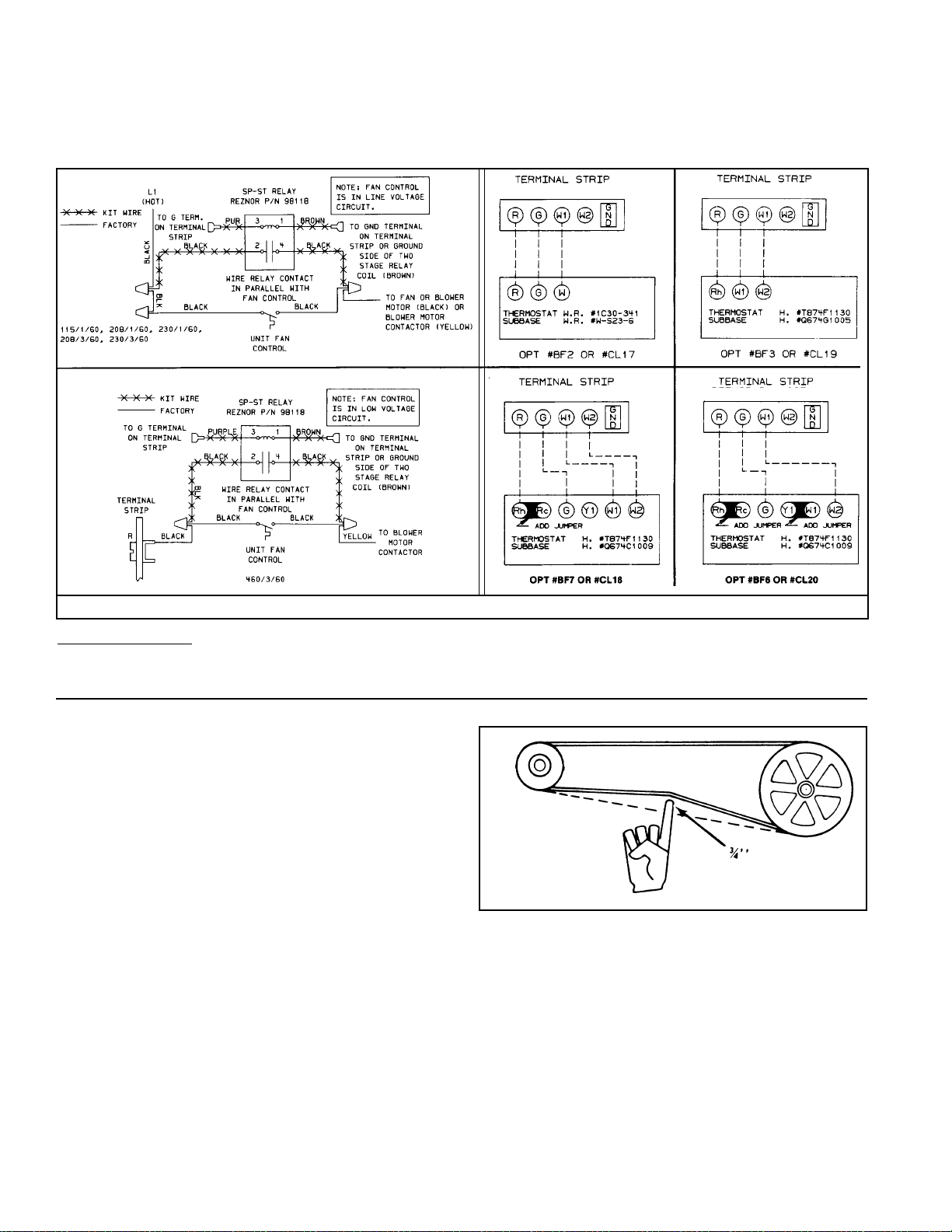
There are some unique wiring requirements with the installation of the optional controls (relay and two-stage). Figure 12 illustrates the wiring of the
relay and the connections required for optional thermostat control.
575/3/60
Figure 12 - Wiring Diagrams for Optional Controls
Multiple Heater Control - These unit heaters are not designed for multiple unit connection to one thermostat. If you require that more than one unit
be controlled by a single thermostat, it will be necessary to use relays in the circuit. Options CL31 and CL32 provide the necessary parts and
instructions for multiple heater control. For more information on these options, see Paragraph 30.
13. Fan Motor
Fan motors are equipped with thermal overload protection of the automatic reset type. Should the motor refuse to run, it may be because of
improper current characteristics. Make certain that the correct voltage
is available at the motor.
NOTE: If the unit is equipped with an optional totally enclosed motor,
the horsepower may be larger than the standard motor. Refer to the
motor nameplate to verify horsepower.
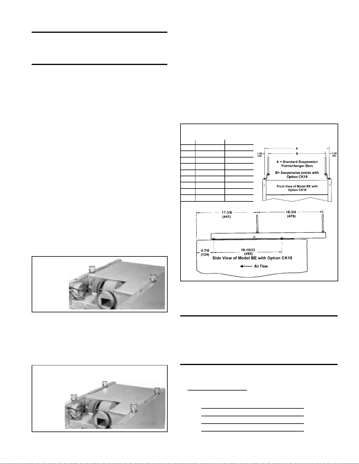
14. Blower Motor
Blower Model Sizes 25-100 are standardly equipped with a direct drive
motor; an optional belt drive motor is available on Sizes 50-100. Blower
Model Sizes 125-400 have an adjustable belt drive motor.
As part of the Check/Test/Start (Paragraph 24), check the belt for proper
tension. Proper belt tension is important to the long life of the belt and
motor. A loose belt will cause wear and slippage. Too much tension
will cause excessive motor and blower bearing wear. Adjust the belt
tension by turning the adjusting screw on the motor base until the belt
can be depressed 1/2-3/4". (See Figure 13.) After correct tension is
achieved, re-tighten the locknut on the adjusting screw.
Most blower motors are equipped with thermal overload protection of
the automatic reset type. If a motor is not equipped with thermal overload protection, the unit will be equipped with a starter. The adjustable
setting on the starter will be factory set to match the amp draw of the
Form 436, Page 16
Figure 13 Adjusting Belt
Tension
motor and sealed. No change should be made to starter set unless the
original motor is replaced.
Starters are supplied from the factory for manual reset operation. If an
overload condition is experienced, the condition must be corrected,
and the starter must be manually reset.
After the installation is complete including all ductwork, the amp draw
of the motor should be checked with an amp meter to verify that the
motor amp rating on the motor nameplate is not being exceeded. Amps
may be adjusted downward by reducing blower speed for by increasing the duct system static pressure. The temperature rise must be within
the range specified on the unit rating plate.
Page 17
15. Blower Speed Adjustment
The blower speed may be adjusted to achieve the desired outlet temperature, as long as the adjustment is within the temperature rise and
the static pressure limits shown on the heater rating plate. Direct drive
motors are factory set as indicated in the chart below. Belt drive motors are factory set at the mid-point between maximum and minimum
blower speeds.
If the duct resistance is low, the blower may deliver too high an air
volume; or if the heater is operated without ductwork, it may deliver
sufficient excess air to overload the motor, causing the overload protector to cycle the motor. Reducing the blower speed will correct these
conditions. If ductwork is added to an installation, it may be necessary
to increase the blower speed. Decreasing blower speed will increase
outlet temperature; increasing blower speed will decrease outlet temperature.
Blower Model Sizes 25-100 with Direct
Drive
Direct drive blower motors have multi-speed taps for speed adjustment. If your installation requires an adjustment of the blower speed,
the motor may be re-wired to an alternate tap by following these instructions.
1. Turn off the gas and the electric power.
2. Remove the left (left when facing the back of the unit) outer side
panel of the heater to reveal the wiring connections.
3. Consult the wiring diagram on the heater and follow the below chart
to choose the wire for the desired adjustment. The asterisk(*) indicates the factory-wired speed.
Model Size Speed Use these Two Motor W i res
25 *Medium *Blue and White
Low Red and White
50 *High *Black and White
Medium Blue and White
High Black and White
75 *Medium *Blue and White
Low Red and White
*High *Black and White
100 Medium Blue and White
Low Red and White
4. Cut the crimped cap from the end of the wire that you intend to use
and strip the insulation.
5. Disconnect the factory-wired connection and re-wire, using the
newly stripped wire.
6. Put a wire nut on the end of the blower motor wire that was disconnected.
7. Replace the heater side panel and turn on the gas and the electric.
Blower Model Sizes 50-400 with Belt Drive
The belt drive on these units is equipped with an adjustable pulley
which permits adjustment of the blower speed. Follow these instructions to adjust the blower speed.
1. Turn off the gas and the electric power.
2. Loosen belt tension and remove the belt.
3. Loosen the set screw on the side of the pulley away from the motor.
4. T o increase the blower speed, decreasing outlet temperature, turn
the adjustable half of the pulley inward. To decrease the blower
speed, increasing the outlet temperature, turn the adjustable half
of the pulley outward. One turn of the pulley will change the speed
8-10%.
5. Tighten the set screw on the flat portion of the pulley shaft.
6. Replace the belt and adjust the belt tension. Adjust tension by turning the adjusting screw on the motor base until the belt can be depressed 1/2-3/4". (See Figure 13.) Re-tighten the lock nut on the
adjusting screw.
7. Turn on the gas and electric. Light the heater following the instructions on the lighting instruction plate.
8. Check the motor amps with an amp meter. The maximum motor
amp rating on the motor nameplate must not be exceeded.
CAUTION: An external duct system static
pressure not within the limits shown on the rating
plate or improper adjustment of the motor pulley
or belt may overload the motor.
16. Blower Rotation
Each blower housing is marked for proper rotation. Rotation may be
changed on single-phase motors by re-wiring in the motor terminal
box. Three-phase motors may be reversed by interchanging two wires
on the 3-phase supply connections.
17. Fan Control
1. A fan control provides the following:
(a) Delay of fan or blower operation to prevent the discharge of
cold air.
(b) Fan or blower operation as long as the unit is hot.
2. The fan control provides additional safety by keeping the fan or
blower in operation in the event that the gas valve fails to close
when the thermostat is satisfied.
3. To be sure that the fan or blower can continue to operate, the power
supply to the heater MUST NOT be interrupted except when servicing the unit.
4. If the customer wants the heater off at night, the gas valve circuit
SHOULD BE OPENED by a single pole switch wired in series
with the thermostat. Some thermostats are provided with this feature.
Multiple units controlled from a single thermostat are shut off in the
same manner. For proper operation, be sure the fan control wiring
is observed.
WARNING: If you turn off the power supply,
turn off the gas. See Hazard Levels, page 2.
NOTE: Low ambient temperatures (less than 40oF) may cause false
cycling of the fan/blower. To prevent this, a time delay relay can be
added to the unit (available with single-stage gas valve only) to activate the fan/blower electrically independent of the heat exchanger or
the room temperature. The low ambient fan control relay can be factory installed; Option BF8 will appear on the heater wiring diagram.
Or, the relay can be field installed; order Option CQ3 (P/N 112779).
This relay is in addition to the fan control The fan control is a safety
device and should never be removed from the heater circuit.
18. Limit Control
All models are equipped with an automatic, non-adjustable reset limit
control that acts to interrupt the electric supply to the redundant main
operating valve in case of motor failure or lack of airflow due to restrictions at the inlet or outlet.
Mfg P/N 98807 Rev 8, Page 17
Page 18
19. Combustion Air Proving
Switch
The combustion air proving switch is a pressure sensitive switch that
monitors air pressure to ensure that proper combustion air flow is available. The switch is a single pole - normally open - device which closes
when a decreasing pressure is sensed in the outlet duct of the flue gas
collection box.
On start-up when the heater is cold, the sensing pressure is at the most
negative level, and as the heater and flue system warm up, the sensing
pressure becomes less negative. After the system has reached equilibrium (about 20 minutes), the sensing pressure levels off.
If a restriction or excessive flue length or turns cause the sensing pressure to become less than the switch setpoint, the pressure switch will
function to shut off the main burners. The main burners will remain off
until the system has cooled and/or the flue system resistance is reduced.
The Table on the right lists the approximate water column negative pressure readings and switch setpoints for sea level operating conditions.
Model Start-Up Equilibrium Set Point Set Point
Size Cold "OFF" "ON"
25-400 -1.0" w.c. -0.60" w.c. -0.47" w.c. -0.64"w.c.
DANGER: Safe operation of this unit requires
proper venting flow . NEVER bypass combustion
air proving switch or attempt to operate the unit
without the venter running and the proper flow
in the vent system. Hazardous conditions could
result. See Hazard Levels, page 2.
20. Gas Valve
Main operating valve is powered by the 24-volt control circuit through
thermostat and safety controls. The main control valve is of the diaphragm type with magnetic pilot servo bleed operators, providing regulated gas flow preset at the factory. The valve body also incorporates a
magnetic valve providing pilot gas control for the electronic ignitor system and redundant or dual valve safety shutoff function.
WARNING: The operating valve is the prime
safety shutoff. All gas supply lines must be free of
dirt or scale before connecting the unit to ensure
positive closure. See Hazard Levels, page 2.
is imposed on that metal probe which is electrically isolated from
ground. When the pilot flame impinges on the flame sensing probe,
the flame acts as a conduction path to ground. The pilot flame rectifies and completes the DC circuit. The ignition controller acknowledges the flame and energizes the main gas valve.)
22. Burners
These unit heaters have individually formed steel burners with accurately die-formed ports to give controlled flame stability without lifting or flashback with either natural or propane gas. The burners are
lightweight and factory mounted in an assembly which permits them
to be removed as a unit for inspection or service.
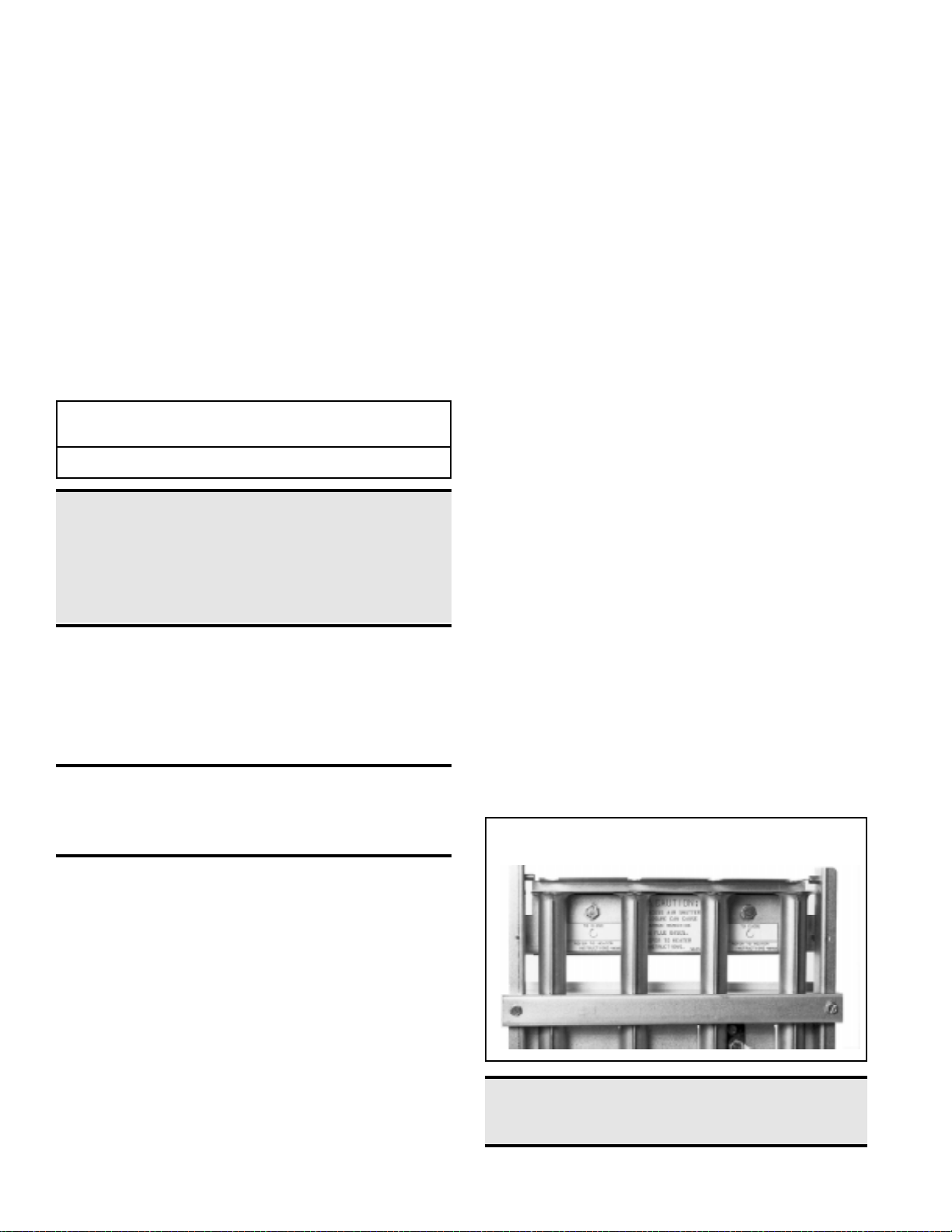
23. Burner Air Adjustment
All sizes of these unit heaters that are equipped with standard aluminized burners are designed to operate without burner air shutters when
fueled with either natural or propane gas. However, Sizes 165 through
400 equipped with optional stainless steel burners (Option AD2) require air shutters (Option AE1) when used with propane gas (Option
AA2).
Optional air shutters, either factory or field installed, are available for
any size model for use where unusual conditions cause excess primary aeration.
Before making any adjustments to the air shutters, allow the heater to
operate for about fifteen minutes. The air shutter adjustment screws
can be reached by opening the bottom panel. (Remove the two screws
located at the rear of the bottom panel and allow the panel to hinge
down from the front.) The adjustment screws for the air shutters are
visible at the rear of the burner rack . See Figure 14.
When making the adjustment, close the air shutters no more than is
necessary to eliminate the problem condition.
Observe the flame for yellow-tipping. A limited amount of yellowtipping is permissible for liquefied petroleum gases. Other fuels should
not display any yellow-tipping.
T wo adjustment screws are used (See Figure 14). Rotating the screws
clockwise closes the shutters, reducing the primary air supply. Counterclockwise rotation opens the shutters, increasing the primary air
supply. The two adjustment screws should be rotated alternately to
open or close the shutters. Attempting to gain adjustment by not alternating between the two screws may cause the shutters to bind.
After proper adjustment has been completed, eliminating the problem
condition, close the bottom panel and replace the retaining screws.
Figure 14 - Air Shutter Adjustment Screws -- Alternate
Turning Screws When Adjusting Shutter
21. Pilot and Ignition System
These unit heaters are equipped with a spark ignited intermittent safety
pilot system that shuts off the pilot gas flow between heat cycles. In
addition, propane units are equipped with a spark pilot system that incorporates a lockout device that stops the gas flow to the pilot if the
pilot fails to light in 120 seconds. The spark pilot with 100% lockout
requires manual reset by interruption of the thermostat circuit. Propane
units require the lockout; natural gas units may be equipped with either
standard spark pilot or spark pilot with lockout (Option AH3). Refer to
the wiring diagram with your heater for pilot system identification and
proper wiring.
The ignition controller in the spark pilot system provides the high voltage spark to ignite the pilot gas and also acts as the flame safety device.
After ignition of the pilot gas, the control electronically senses the pilot
flame. (A separate solid metal probe in the pilot burner assembly is
employed for the flame sensing function. A low voltage electrical signal
Form 436, Page 18
DANGER: Failure to install and/or adjust air
shutters according to directions could cause
property damage, personal injury , and or death.
Page 19

24. Check Installation and Start-Up
Check the installation prior to start-up:
o Check suspension. Unit must be secure and level.
o Blower Model - Check to be sure that all shipping supports
have been removed. Rubber feet must be on the motor bracket
bolts. See Paragraph 4.
o Check clearances from combustibles. Requirements are shown
in Paragraph 6.
o Check vent system to be sure that it is installed according to
the instructions in Paragraph 9.
o Check piping for leaks and proper gas line pressure. Bleed
gas lines of trapped air. See paragraph 10.
o Check electrical wiring. Be sure all wire gauges are as rec-
ommended. A service disconnect switch should be used.
V erify that fusing or circuit breakers are adequate for the load
use.
o Check that any field-installed options have been included in
the installation.
o Blower Model - Check belt tension. See Paragraph 14.
Start-Up -- Typical Operating Sequence:
1. Set thermostat at lowest setting.
2. T urn on main and pilot manual gas valves.
3. Turn on the power to the unit.
4. Set the thermostat to desired setting.
5. Thermostat calls for heat, energizing the venter motor.
6. Venter pressure switch closes, firing the unit, after pilot proving sequence.
7. Fan control senses heat exchanger temperature, energizing
the fan or blower motor.
8. If the flame is extinguished during the main burner operation, the safety switch closes the main valve and recycles the
spark gap.
On units equipped with lockout device, if the pilot is not established within 120 seconds, the unit locks out and must be
reset by interrupting power to the control circuit. (See lighting instructions on the heater.)
Check installation after start-up:
o With the unit in operation, measure manifold gas pressure.
Manifold pressure for natural gas should be 3.5" w.c. and
10" w.c. for propane gas. See Paragraph 10.
o Turn the unit off and on, pausing two minutes between each
cycle. Observe for smooth ignition.
o Blower Model - Check motor amps with an amp meter. The
maximum amp rating on the motor nameplate must not be
exceeded.
o Place 'Owner's Envelope" containing Limited Warranty Card,
this booklet, and any optional information in an accessible
location near the heater. Follow the instructions on the envelope.
DANGER: The gas burner in this gas-fired equipment is designed and equipped to provide safe
and economically controlled complete combustion. However, if the installation does not permit
the burner to receive the proper supply of combustion air, complete combustion may not occur.
The result is incomplete combustion which produces carbon monoxide, a poisonous gas that can
cause death. Safe operation of indirect-fired gas burning equipment r equires a properly operating
vent system which vents all flue products to the outside atmosphere. FAILURE TO PROVIDE
PROPER VENTING WILL RESULT IN A HEALTH HAZARD WHICH COULD CAUSE
SERIOUS PERSONAL INJURY OR DEATH.
Always comply with the combustion air requirements in the installation codes and in Paragraphs
6 and 7. Combustion air at the burner should be regulated only by manufacturer-provided
equipment. NEVER RESTRICT OR OTHERWISE ALTER THE SUPPLY OF COMBUSTION
AIR TO ANY HEATER. Indoor units installed in a confined space must be supplied with air for
combustion as required by Code and in Paragraph 7 of this heater installation manual. MAINT AIN
THE VENT SYSTEM IN STRUCTURALLY SOUND AND PROPERLY OPERATING
CONDITION.
Mfg P/N 98807 Rev 8, Page 19
Page 20
OPTIONAL EQUIPMENT
This section contains a brief description of the more frequently specified field-installed options. All option packages include complete assembly
and installation instructions.
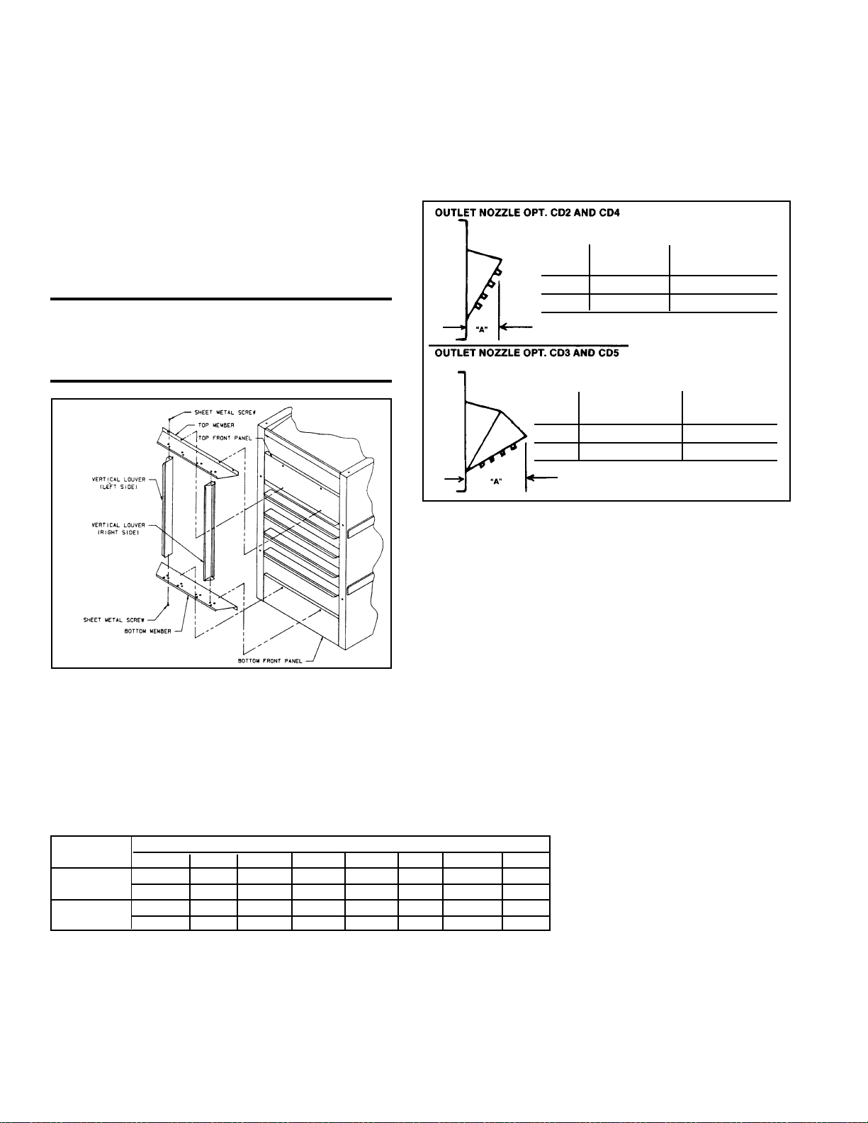
25. Optional Vertical Louvers Option CD1
The purpose of the addition of optional vertical louvers is to increase the air pattern spread. The vertical louver assembly is designed to be field assembled and installed. Refer to the instructions
packaged with Option CD1 for a list of components and step-bystep installation instructions (Do not add optional vertical louvers to
a fan-type heater with downturn nozzle Option CD3. See Paragraph
26.)
CAUTION: To avoid getting burned, adjust
louvers prior to heater operation. If louvers
need re-adjusting after start-up, wear
protective gloves.
Figure 15 Optional
Vertical
Louvers
26. Optional Downturn Air Nozzles
- Options CD2, CD3, CD4, & CD5
Sizes "A" Range of
Air Deflection
25-125 9" (229mm) 25o-65
165-400 13" (330mm) 25o-65
Figure 16 - Optional
Downturn Nozzles
Sizes "A" Range of
Air Deflection
25-125 16-1/2" (419mm) 50o-90
165-400 23-1/2" (597mm) 50o-90
Unit heaters may be specified with optional downturn air nozzles to direct
the discharge tempered air. The nozzles are shipped separately for field
assembly and installation. The horizontal louvers are removed from the
heater and re-installed into the outlet of the downturn nozzle.
The addition of a downturn nozzle requires four-point heater suspension.
T wo hanger brackets are included with downturn nozzle options and must
be added to fan-type heaters with standard two-point suspension. Suspension point dimensions are found in Dimension Charts in Paragraph 3. On
fan-type heaters, do not install Option CD5 or use vertical louvers with
Option CD3.
o
o
o
o
27. Optional Duct Flange - Option CD9 (Blower Models only)
Blower-type unit heaters may be connected to ductwork. The duct flange option is designed to adapt
the heater outlet (supply side) for connection to ductwork.
Ductwork connection sizes are shown in the chart below.
Follow the installation instructions included with the option package.
Model BE Duct Connection Sizes (inches and mm) with Optional Duct Flange
Size 25-50 75 100 125 165 200 250-300 400
Height 15-7/8 15-7/8 15-7/8 15-7/8 23-7/8 23-7/8 23-7/8 23-7/8
403 403 403 403 606 606 606 606
Width 10-3/4 12-3/4 14-3/4 20-1/2 17-1/2 20-1/2 26 34-1/4
273 324 375 521 445 521 660 870
Form 436, Page 20
Page 21

28. Optional Polytube Adapter - Options CD6, CD8, and CD11
(Blower Models only)
The polytube adapter option is designed to adapt this blowertype heater for use with polytube ductwork. The use of
polytubes for air distribution is common in greenhouse applications and some industrial applications. A polytube distribution system delivers warm air to a specific area, reducing the
need for complete area heating. The polytube adapter is available in three installation designs making it adaptable to many
applications and building structures.
Figure 17 - Polytube Adapter
Illustration shows Option
CD8, Polytube Adapter
for Floor-Mounted
Heater. Options CD6 and
CD11 are for Suspended
Heaters.
WARNINGS: This adapter is to be used
only on units equipped with a blower. At
no time should the free area in the polytube
be less than the listed minimum. Failure to
comply with these warnings could result
in severe personal injury, death and/or
property damage.
The following chart shows specification information covering the use of polytubes with these blower-type unit heaters.
CFM at Polytube Minimum Free
Size .25" Diameter Area (square
ESP (inches) Inches)
75 925 18 110
100 1235 18 145
125 1540 18 185
130 1600 24 190
165 2035 24 240
200 2465 24 300
250 3085 24 360
300 3700 24 425
400 4935 24 550
The polytube adapter option package does not include polytubing.
Polytubing can be obtained from a supply distributor such as FOF
Products, Inc., P. O. Box E, 1505 Racine Street, Delevan, WI
53115; ACME Engineering Co., P.O. Box 978, Muskogee, OK
74402; or any local greenhouse supply distributor. Some local
code authorities require the polytube material to be a listed material. Consult code authority having jurisdiction and the polytube
supplier to determine the appropriate polytube material and recommended methods of suspension.
Holes
Number 37pairs 75 pairs 75 pairs
Diameter 1-1/2" 1" 1"
Spacing 16" 12" 16"
Number 50 pairs 50 pairs 100 pairs 94 p airs
Diameter 1-1/2" 1-1/2" 1" 1"
Spacing 12" 18" 12" 16"
Number 40 pairs 60 pairs 60 pairs 125 pairs
Diameter 1-7/8" 1-1/2" 1-1/2" 1"
Spaci ng 15" 15" 20" 12"
Number 40 pairs 60 pairs 60 pairs 125 pairs
Diameter 1-7/8" 1-1/2" 1-1/2" 1"
Spaci ng 15" 15" 20" 12"
Number 50 pairs 50 pairs 75 pairs 75 pairs 75 pairs
Diameter 1-7/8" 1-7/8" 1-1/2" 1-1/2" 1-1/2"
Spaci ng 12" 18" 16" 20" 24"
Number 42 pairs 42 pairs 60 pairs 60 pairs 100 pairs
Diameter 2-1/4" 2-1/4" 1-7/8" 1-7/8" 1-1/2"
Spaci ng 14" 21" 20" 25" 18"
Number 40 pairs 60 pairs 60 pairs 60 pairs 60 pairs
Diameter 2-1/2" 2" 2" 2" 2"
Spaci ng 15" 15" 20" 25" 30"
Number 75 pairs 75 pairs 75 pairs 75 pairs 75 pairs
Diameter 2" 2" 2" 2" 2"
Spaci ng 9" 12" 16" 20" 24"
Number 60 pairs 60 pairs 60 p airs 100 p airs 100 pairs
Diameter 2-1/2" 2-1/2" 2-1/2" 1-7/8" 1-7/8"
Spacing 10" 15" 20" 15" 18"
Suggeste d Hole Sizes and Locations
Length of Polytube
50 Ft 75 Ft 100 Ft 125 Ft 150 Ft
Conversion T able (Diameter to Area)
Diameter of the Hole Area of the Hole
(inches) (sq in)
2-1/2 4.91
2-1/4 3.98
2 3.14
1-7/8 2.76
1-1/2 1.76
1 0.785
Mfg P/N 98807 Rev 8, Page 21
Page 22

29. Optional Guards Options CD10 & CD12
(Blower Models only)
These guard options are designed to provide complete protection from the rotating drive and/or blower components.
Option CD12 is designed for use with Sizes 25-100 with
standard direct drive motor. This kit includes only the blower
inlet guard.
Option CD10 is designed for use on Sizes 50-400 with a
belt driven motor and includes both the belt guard and the
blower inlet guard.
Figure 18 - Optional Guards
Optional
Belt
Guard
Installed
Optional
Blower Inlet
Guard
Installed
30. Optional Multiple Heater Control Options CL31 & CL32
The multiple heater control options are designed to permit the control of up to six
heaters (one master and five slave units) with a single thermostat or a time clock
and single/multiple thermostats.
For maximum safety, the multiple control is one in the low voltage circuit. These
multiple heater control options may not be used with two-stage gas valves.
Figure 19 - Multiple Heater Control Wiring with Options CL31
and/or CL32
31. Optional Blower/Filter Cabinet -
Options CW1, CW2, or CW3
(Blower Models Only)
The blower/filter cabinet option is available for all sizes. The blower/filter cabinet is shipped separately for field assembly and installation. The cabinet is adaptable for use with either 1" or 2" filters and may be connected to a return air duct
(includes 3/4" duct flange). Option CW1 does not include filters; CW2 includes
1" permanent aluminum filters; and CW3 includes 2" permanent aluminum
filters.
Figure 20 - Optional Field-Installed Blower/Filter Cabinet
Blower Cabinet with
Filters (Option CW2
or CW3) -- side panel
removed to illustrate
interior of cabinet
Blower Cabinet
without Filters
(Option CW1)
Model Filter Replacement P/N
Size Qty Size 1" Filter 2" Filter
25-125 1 20 x 20 101608 101621
165-200 1 16 x 25 101609 101622
1 20 x 25 101610 101623
250-300 2 16 x 20 101607 101620
2 20 x 20 101608 101621
400 2 16 x 25 101609 101622
2 20 x 25 101610 101623
Form 436, Page 22
Page 23

SERVICE AND MAINTENANCE
WARNING: If you turn off the power supply,
turn off the gas. See Hazard Levels, page 2.
This unit will operate with a minimum of maintenance. To ensure long
life and satisfactory performance, a heater that is operated under normal conditions should be inspected and cleaned at the start of each
heating season. If the heater is operating in an area where an unusual
amount of dust or soot or other impurities are present in the air, more
frequent maintenance is recommended.
The following procedures should be carried out at least annually (See
Paragraphs 32-41 for specific instructions.):
1. Clean all dirt and grease from the primary and secondary combustion air openings.
2. Fan Models - Clean the fan blade, fan guard, and motor.
3. Blower Models - Clean the blower, the belt guard, the inlet guard,
and motor of all dirt and grease. Check the blower belt for tension
and wear. Replace a worn belt that may fail before the next scheduled maintenance check.
4. Clean the heat exchanger both internally and externally.
5. Check the pilot burner and main burners for scale, dust, or lint accumulation. Clean as needed.
6. Check the vent system for soundness. Replace any parts that do not
appear sound.
7. Check the wiring for any damaged wire. Replace damaged wiring.
(See Paragraph 11 for replacement wiring requirements.)
NOTE: Use only factory-authorized replacement parts.
visible. Do the
following:
(a) Disconnect the
pilot tubing from the
pilot burner.
(b) Disconnect the
flame sensing wire
and high tension
(spark) lead from
the ignition controller.
7A. Heaters manufactured beginning 8/91 (Serial No. Date Code
AQH) - The burner rack is indexed as illustrated in Figure 23. While
supporting the burner rack, remove the screws (two or three) that
hold the burner rack support. (For screw location, refer to Figure
23.) Remove the burner rack support allowing the burner rack assembly to swing down (See Figure 24).
Pilot
Tubing
Figure 22 - Spark Pilot Location
Flame
Sensor Lead
Burner Rack Support
with Indexing
Burner Rack
Support on units
Screws
manufactured
prior to 8/91 was
not indexed
Figure 23 - Burner Rack Support and Retaining Screws
32. Burner Rack Removal
These unit heaters have a convenient bottom access panel. The pilot is
attainable with the bottom panel open. With the access panel removed,
the burner rack assembly will hinge down for removal. Use the following step-by-step instructions for removal of the bottom access panel
and the complete burner rack assembly.
Instructions for Burner Rack Removal (See
Figures 21-24.)
1. Shut the gas supply off ahead of the combination valve.
2. Turn off electric supply.
3. Remove the two sheet metal screws located at the rear of the bot-
tom panel.
4. Allow bottom
panel to hinge
down from the
front.
5. Push in one of
the two springloaded hinge pins
located at the
front of the bottom panel (inside), and completely remove
the bottom
panel.
6. The bottom of
the pilot is now
Push
hinge
pin to
remove
bottom
panel
Figure 21- Bottom Access Panel Open
Pilot
Location
7B. Heaters manufactur ed prior to 8/91 (Serial No. Date Code AQH)
Loosen the sheet metal screws (two or three) located at the front of
the burner rack assembly. See Figures 23. These screws retain the
burner rack support. While supporting the burner rack assembly,
slide the burner rack support and remove it from the screws, allowing the burner rack assembly to swing down (See Figure 24).
8. To Remove the Burner Rack -- With the burner rack assembly
"hanging" down, lift up on the rear and slide the assembly up and
out of the manifold support brackets.
Figure 24 Burner Rack
Hinged Down
Mfg P/N 98807 Rev 8, Page 23
Page 24

32. Burner Rack Removal (cont'd)
Figure 25
Burner Assembly Support Brackets
Burner Orifices
moval, Paragraph 32. The pilot can be removed to check the wiring,
the spark gap, or to remove the orifice for cleaning. When the pilot is
re-installed, be sure to include the pilot hole cover plate.
Pilot Hole
Cover
Plate
Figure 26 Burner Rack
Completely
Removed
9. To remove the individual burners:
a. Remove the flash car-
ryover (one screw per
burner).
b. With the burner rack
upside down, remove
the sheet metal screws
(located at the rear)
that retain the burner
holddown.
c. Lift the rear of the
burner upward slightly
and pull back, removing the individual
burners.
d. To replace individual burners, reverse the above procedure.
10. To replace the burner rack assembly and the bottom panel, reverse the above procedure (Steps 1-8).
Individual burners may be cleaned using air pressure. Use an air nozzle
to blow out scale and dust accumulation from the burner ports. Alternately, blow through burner ports and venturi.
Figure 27 - Individual Burners
CAUTION: Eye protection is recommended.
Use a fine wire to dislodge any stubborn particles. Do not use anything
that might change the port size.
When any service is completed, be careful to reassemble correctly to
ensure that no unsafe conditions are created. When re-lighting, always
follow the lighting instructions on the heater.
33. Pilot and Ignition System
The pilot can be serviced by opening the bottom access panel of the
heater. Follow the first four steps of instructions for Burner Rack Re-
Form 436, Page 24
Figure 28 - Pilot Removal
Spark gap must be maintained to .100". (See Figure 29.)
Figure 29 Pilot Burner
Spark Gap
In the event the pilot
flame is short and/or
yellow, check the pilot orifice for blockage caused by lint or
dust accumulation.
Remove the pilot orifice and clean with air
pressure. Check and
clean the aeration slot
in the pilot burner.
Figure 30 Pilot
Assembly
CAUTION: Due to high voltage on pilot spark
wire and pilot electrode, do not touch when
energized. See Hazard Levels, page 2.
The ignition controller of the intermittent electronic ignition pilot sys-
tem is visibly located on the back of the heater. (See Figure 31.) Do not
attempt to disassemble the ignition controller. There are no field replaceable components in the control enclosure. However, each heating
season the lead wires should be checked for insulation deterioration
and good connections.
Proper operation of the electronic spark ignition system requir es a
minimum flame signal of .2 microamps as measured by a
microampmeter.
For further information and check out procedure on the intermittent
electronic ignition pilot system, refer to the manufacturer's control operating instructions supplied with the heater.
Page 25

Figure 31
- Ignition
Controller
Location
Ignition
Controller
for Spark
Pilot
34. Burner Orifices
Heaters are shipped with orifices of proper size and type for gas and
altitude specified on the order. When ordering replacement orifices,
give BTUH content, specific gravity of gas, and altitude, as well as
model and serial number of the heater.
Main Burne r Orifices (sea level)
Model Natural Gas Propane G as
Size Drill
25 51 39650 2 60 95936 2
50 47 84853 3 1.2MM 63003 3
75 45 38678 4 1.3MM 64676 4
100 44 11833 5 55 11830 5
125 44 11833 6 55 11830 6
165 35 11831 5 1.65MM 96344 5
200 35 11831 6 1.65MM 96344 6
250 35 11831 8 1.65MM 96344 8
300 35 11831 9 1.65MM 96344 9
400 35 11831 12 1.65MM 96344 12
Pilot
Orifice
Natural - P/N 103034 Propane - P/N 98695
WARNING: Do not use this table for gas conversion.
Additional parts are required; contact your Reznor
Distributor.
Siz e
Orifice
P/N
Qty Drill Size
Orifice
P/N
Qty
CAUTION: Eye protection is recommended.
36. Heat Exchanger
The outside of the heat exchanger can be cleaned from the front of the
heater with an air hose and/or a brush. Remove all accumulated dust
and grease deposits.
The inner surfaces of the heat exchanger can be reached for cleaning
with the burner rack removed. (See Paragraph 32.) Cleaning can be
done with a long furnace brush or a heavy wire to which steel wool has
been attached. Brush up and down inside each heat exchanger tube
until all foreign material is removed. A flashlight is helpful in examining the upper section of the tube.
37. Fan or Blower
Remove dirt and grease from the motor.
On fan model units, remove dirt and grease from the fan guard and
blades. Use care when cleaning the fan blades to prevent causing misalignment or imbalance. Check that the hub of the fan blades is secure
to the shaft.
On blower models, remove the grease and dirt from the blower housing and check the belt for wear and proper tension (See Paragraph 14.)
Lubricate if the motor has oil cups or grease fittings. The motor supplied as standard has lifetime lubrication and sleeve bearings.
On blower models, check current draw to motor rating plate.
Fan Models: Follow these instructions for replacement of the fan guard,
fan motor or fan blades.
1. If the heater is installed, turn off the gas and disconnect the electric
power.
2. Remove the left outer side panel (left when facing the rear of the
unit). Disconnect the fan motor wires.
3. Depending on the date that the heater was manufactured, it will have
either a lower-half fan guard only, two-piece full fan guard, or a onepiece full fan guard. If the unit has a two piece fan guard, remove the
tension mounted upper half fan guard and the four screws that hold the
lower half. If the unit has a one-piece fan guard, remove all of the
screws that retain the fan guard. Remove the assembled parts (the fan
guard, the motor and the fan blade).
4. Disassemble and replace whatever parts are needed and reassemble
using whatever part(s) are being replaced and the original parts. If the
fan guard is being replaced, it is important that the same hardware be
used for attaching the motor to the fan guard as was used with the
original guard. These screws are especially made to cut through the
coating on the fan guard to provide adequate grounding for the motor.
35. Flash Carryover
See Figure 32. The burner carryover system receives its gas supply
from the main burner ports. Check the carryover assembly and also the
main burner ports for cleanliness. Clean with air pressure.
Flash
Carryover
Figure 32 -
Burner
Rack Flash
Carryover
Figure 33 Proper Position
of the Fan
Blade on the
Motor Shaft
Be sure the fan
blade is in proper
position on the
shaft. Position the
fan as shown in
Figure 33 according to the chart on
the right.
Fan
Motor
A
Model Set Screw “A” Hub to
Size Torque In-Lbs Motor
25 80 + or - 10 1-1/4" (32mm)
50 80 + or - 10 3/8"(10mm)
75 80 + or - 10 1/8" (3mm)
100-125 120 + or - 10 2-1/2" (64mm)
165-400 150 + or - 10 2-1/2" (64mm)
Mfg P/N 98807 Rev 8, Page 25
Fan Hub
Page 26

37. Fan (cont'd)
Position the assembly on the heater. Attach the fan guard at the center
mounts. (IMPORTANT: If replacing the fan guard, use the screws
that held the original fan guard. These specially designed screws will
cut through the coating on the fan guard to provide a ground for the fan
motor.)
Rotate the fan blade to check for adequate clearance. If adjustment is
required, loosen the mounting screws, re-position the fan guard, and
tighten the screws. Rotate the fan blade and re-check for adequate clearance. Repeat this procedure until the assembly is positioned properly.
5. If necessary, drill the required upper and lower fan guard mounting
holes. Attach the fan guard at all upper and lower mounting points
using either the screws removed or field-installed sheet metal screws.
6. Reconnect the fan motor wires and replace the outer side panel.
7. Restore power to the heater and turn on the gas. Light, following the
instructions on the lighting instruction plate. Check for proper operation.
38. Venter Motor
Remove dirt and grease from the motor housing. Power venter motor
is permanently lubricated.
The vent relay controls the venter motor. If the relay contacts fail to
close the venter motor will not run. If the relay contacts fail to open,
the venter motor will not shut off, preventing the combustion air pressure switch from opening.
39. Operating Gas Valve
The gas valve requires no field maintenance except careful removal of
external dirt accumulation and checking of wiring connections. Instructions for testing pressure settings are in Paragraph 10.
CAUTION: The operating valve is the prime
safety shutoff. All gas supply lines must be free
of dirt or scale before connecting to the unit
to ensure positive closure. See Hazard Levels,
page 2.
40. Fan and Limit Controls
If it is determined that the fan or limit control needs replacing, use only factory-authorized replacement parts that are designed for your heater.
Instructions for replacing fan or limit control:
1. Turn off the electric power and shut off the gas supply.
2. Remove the outer left side panel (left when facing the back of the unit). Remove the access panel. (See Figure 34.)
3. Remove defective controls and install new controls in the same mounting holes. Use only factory-authorized replacement parts.
4. Replace access panel and side panel.
5. Turn on the electric power and the gas supply.
6. Relight following the lighting instructions on the heater.
Figure 34 Access to
Controls
Remove
Control
Access
Panel
41. Vent System
Check the vent system at least once a year. Inspection should include all
joints, seams, and the vent cap. Replace any defective parts.
Limit
Control
Fan
Control
Form 436, Page 26
Page 27
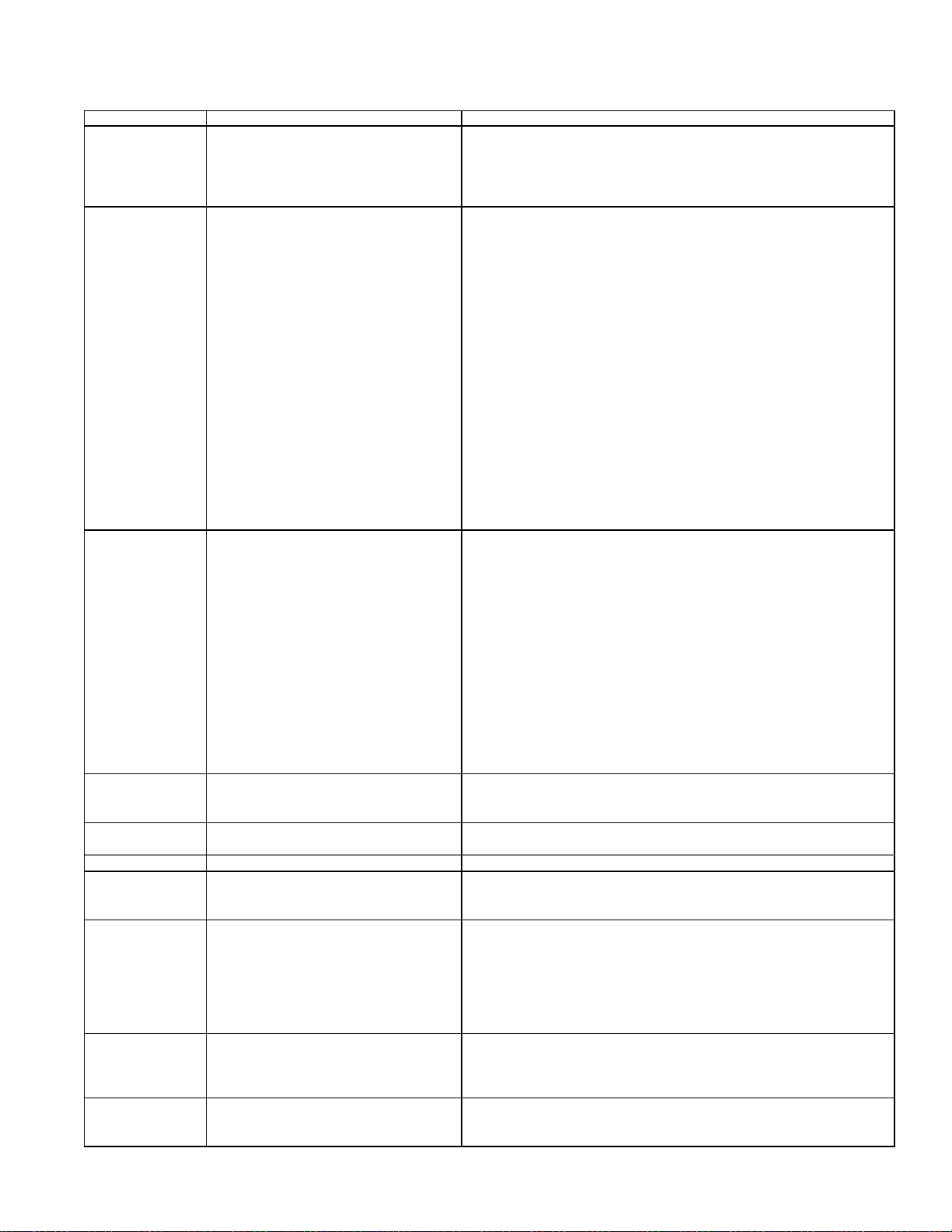
42. T roubleshooting
TRO U B LE PRO BAB L E C AU S E REMEDY
Vente r motor will
not start
Pilot will not light 1.
(spark ignitio n 2.
system) 3.
No power to unit.
1.
No 24 volt power to venter relay.
2.
Vent er relay defect ive.
3.
Defect ive m oto r o r cap acit or.
4.
Manual valve not open.
Air in gas line.
Dirt in pilot o r ifice.
Gas pressure too high or too low.
4.
Kinked pilot tubing.
5.
Pilot valve does not open.
6.
No spark:
7.
Loose wire connect ions
a)
T ransformer failure.
b)
Inco rr ect spark gap.
c)
Spark cable shorted t o ground.
d)
Spark electrode shorted t o ground.
e)
Draft s affecting pilot.
f)
Turn on power, check supply fuses, or circuit breaker. If unit is equipped with
1.
unit-m o unt ed disconn ect switch , ch eck circuit breaker ( See Paragraph 11).
T urn up therm ostat ; ch eck co n trol transfo rm er o ut p ut.
2.
Replace relay.
3.
Replace motor o r cap acit or.
4.
Open m an ual valve.
1.
Bleed gas line.
2.
Remove an d clean with compressed air o r solven t (do no t ream ).
3.
Adjust supply pressure. (See Paragraph 10).
4.
Replace tubing.
5.
If 24 v olt av ailable at valve, replace valve.
6.
7.
Be certain all wires conn ections are solid.
a)
Be certain 2 4 v olts is available.
b)
Maint ain spark gap at .100".
c)
Replace wo r n o r grounded sp ar k cable.
d)
Replace pilot if cer am ic spark electrode is cracked or grounded.
e)
Make sure all panels are in place and tightly secured to pr ev en t drafts at pilot.
f)
g)
h)
8.
circuit by above causes.
Pilot lights, main 1.
valve will not open 2.
(Spark Ign itio n
system)
No heat (Heater 1.
O perating) 2.
Cold air de livered 1.
On Start- up 2.
During O pera tion 3.
Motor will not run 1.
Motor turns o n 1.
and off whil e 2.
burner is operating
(See motor cuts o ut
on overload 4.
below) 5.
Fan m otor cuts 1.
out on overload 2.
Blower motor 1.
cuts o ut on
overload 3.
9.
a)
b)
3.
a)
b)
continues)
c)
d)
e)
3.
2.
3.
3.
exchan ger t ube. Surface con tact is required.
causing false cycling.
3.
4.
2.
Ignition control not grounded.
Faulty ignition cont roller.
Optional lockout device interrupt ing cont rol
Faulty combustion air proving switch.
Manual valve not open.
Main valve not operat ing.
Defect ive v alv e.
Loose wire connect ions.
Ignition control does not power main valve.
Loose wire connect ions.
Flame sensor grounded. (Pilot lights - spark
Gas pressure in co r rect.
Cracked ceramic at sensor.
Faulty ignition cont roller.
Inco rr ect man ifo ld pressure or o r ifices.
Cycling on limit c ontrol.
Improper thermostat location or adjustment. 3. See thermostat man ufact urer's instructio n s.
Fan control improperly wired
Defect ive f an co n trol.
Incorrect manifold pressure.
Circuit open.
Fan control inoperative.
Defect ive m oto r o r cap acit or.
Fan control improperly wired.
Defect ive f an co n trol.
Po or con tact between fan co n tro l and heat
Motor overload device cycling on and off.
Low ambient t emperature (less than 4 0
Low or high voltage supply .
Defect ive m oto r .
Poor air flow.
Defect ive bearing or lubricatio n .
Improper motor pulley and/or adjustment.
Imp roper static pressure i n th e duct system.
Low voltage.
o
Make certain ignition co ntr o l is grounded to furnace ch assis
g)
If 24 volt is available to ignition controller and all ot her causes have been
h)
eliminated, rep lace ignition co n trol.
Reset lockout by int errupt ing cont rol at thermostat.
8.
Replace combustion air pro v ing switch.
9.
Open m an ual valve.
1.
2.
If 24 v olt is measured at valv e co n n ections and valve r em ain s closed, replace
a)
valve.
Check and t ight en all wiring conn ections.
b)
3.
Check and t ight en all wiring conn ections.
a)
Be certain flame sensor lead is not grounded or insulation or ceramic is not
b)
cracked. Replace as required.
Set supply pressure at 5" w.c. to 14" w.c. for natural gas and 11" w.c. to 14"
c)
w.c. for propane gas.
Replace sensor.
d)
See Paragraph 33. If all check s indicate no ot her cause, replace ign ition
e)
contro ller. DO NOT ATTEMPT TO REPAIR IGNIT ION CONTROLLER.
T HI S DEVICE HAS NO FI EL D REP L ACEABLE P ARTS.
Check manifold pressure (See Paragraph 10).
1.
Check air t h r o ughput (See Paragraph 15).
2.
Connect as per wiring diagram.
1.
Replace fan con trol.
2.
Check man ifo ld line pressure (See P ar agraph 1 0 ) .
3.
Check wiring and connections. .
1.
Replace fan con trol.
2.
Replace motor o r cap acit or.
3.
Connect as per wiring diagram.
1.
Replace fan con trol.
2.
Check for bent mounting or loose mounting screws.
3.
Check mo tor load against mo tor r ating plate. Replace moto r if n eeded.
4.
F)
Install fan delay relay kit (See Paragraph 17.)
5.
Correct electric supply .
1.
Replace motor.
2.
Clean moto r, fan and fan guard.
3.
Lubricate bearings or replace mo tor .
4.
See instruct ions in P aragraph 14.
1.
Adjust duct sy ste m damp e rs.
2.
Check power supply.
3.
Mfg P/N 98807 Rev 8, Page 27
Page 28

FOR SERVICE OR REPAIR, FOLLOW THESE STEPS IN ORDER:
FIRST: Contact the installer.
Name _______________________________________________________________________________________
Address ________________________________________________________________________________________
________________________________________________________________________________________
________________________________________________________________________________________
Phone ________________________________________________________________________________________
SECOND: Contact the nearest distributor (See telephone Yellow Pages.)
THIRD: Contact: REZNOR
150 McKinley Avenue
Mercer, PA 16137
Phone: (724) 662-4400
Model No. ______________________________________________________________________________________________
Unit Serial No. __________________________________________________________________________________________
Date of Installation _______________________________________________________________________________________
®
/Thomas & Betts Corporation
Form 436, Page 28
©1999 Thomas & Betts Corporation, All rights reserved. Printed in the U.S.A.
Trademark Note: Reznor® is registered in the United States and other countries. All other trade-
marks are the property of their respective organizations.
MANUFACTURER OF GAS, OIL, ELECTRIC HEATING AND VENTILA TING SYSTEMS
999 10M YL Form 436 (Version A.8)
 Loading...