

Page 1

NOMARK 65/99
Zone Industrielle, 3
ème
Rue
B. 6040 JUMET
Tél. : +32 (0)71.91.97.60
Fax : +32 (0)71.91.96.71
www.thomas-welding.com
Manuel NOMARK_65_99_Anglais_01.doc
Page 2
FOREWORD
Your new THOMAS stud welder is carefully constructed of the finest components and material
available. Used properly, this equipment will give you years of efficient profitable service.
This manual has been specifically prepared for use in familiarizing personnel with the design,
installation, operation, maintenance and trouble-shooting of this equipment. Careful consideration
should be given to all the information presented to assure the proper performance of this
equipment.
A careful study of this manual will enable you to understand how the welders operate to insure
proper performance under all conditions.
GUARANTEE
The electrical and mechanical components of your THOMAS stud welder are thoroughly
performance inspected prior to assembly in the welder. The assembled welder is completely
performance checked. The welder is delivered to you in functional electro-mechanical condition. All
parts used in the assembly of the welder and its accessories are fully warranted for a period of one
(1) year from the date of delivery.
Under this warranty, the manufacturer reserves the right to repair or replace in its plant in JUMET
(BELGIUM), at its option, defective parts which fail during the warrantee period. Notice of any claim
for warranty repair or replacement must be furnished to the manufacturer by the purchaser within
five (5) days after the defect is first discovered. The manufacturer does not assume any liability for
paying shipping costs or for any labor or material furnished where such costs are not expressly
authorized in writing.
We do not warrant THOMAS stud welders, parts, or accessories against failures resulting from
misuse, abuse, improper installation, maladjustment or use not in accordance to the operating
instructions furnished by the manufacturer. The warranty is valid only when studs are purchased
from sources approved by the manufacturer.
Installation servicing or troubleshooting must only be done by qualified personnel trained to
work on this type of equipment.
The equipment must always be accompanied by the instructions of
operation, instructions, safety, inspection and maintenance, applicable
information relating to the devices and security instructions required at the
place of uses of the machine. The security instructions concerning welding
in general must also be well known and applied.
1
Page 3
TABLE OF CONTENTS
Page
1 Introduction
4
1.1
General information
- For your safety
- Field of application of the stud welding system
- Features of the stud welding system
5
5
5
6
1.2 Components of the stud welding system
8
1.3 Functional principle of the stud welding system
7
1.4 Stud welding gun C0
8
1.5 Stud welding gun C1 10
1.6 Meaning and description of symbols 12
1.7 Other descriptions 14
1.8 Welding elements (studs) 14
1.9 Material combinations 15
1.10 Centring device (For future applications) -
1.14 Angle bracket 16
1.15 Bending device 16
1.16 Chucks (standard) 16
1.17 Chucks (for insulation pins) 17
1.18 Chuck extension 17
1.20 Welding on centre punches or scribed lines 17
2 Work safety and rights 18
2.1 Safety symbols 19
2.2 Safety information 20
2.3 Proper use 26
2.4 Guarantee and liability 28
2.5 Copyright 29
2.6 EC Declaration of conformity 30
3 Delivery ... Installation 31
3.1 Extent of delivery 32
3.2 Receiving inspection 32
3.3 Storage 32
3.4 Transport 32
3.5 Place of use 33
3.6 Erection 33
3.7 Power connection 33
2
Page 4
3
Page
4 Operation 34
4.1
Connections of the power unit
Connecting the earth cable
Connecting the welding gun
36
36
37
4.2 Chuck preparation 38
4.3 Adjusting the C0 and C1 guns 40
4.4 Adjusting the CHP (For future applications) -
4.5 Tips for good welding results 42
4.6 Work procedure during welding 43
4.7
Testing the weld
Visual inspection
Impact bending test
45
45
46
5 Maintenance 47
5.1 Troubleshooting 48
5.2 Care and cleaning 52
5.3 Maintenance intervals 53
5.4 Fuse elements 54
5.5 Technical specifications NOMARK 65 / 99 55
5.6 Explosion view of NOMARK 65 / 99 56
5.7 Block circuit diagram 58
5.8
Technical specifications C0 Gun
59
5.9 Explosion view 60
5.10 Welding accessories 63
5.11
Technical specifications C1 Gun
65
5.12 Explosion view 66
5.13 Welding accessories 68
5.14 Iso Kit for C1 71
5.15 Blank page for notes 73
Page 5

1 Introduction
1.1 General information
1.2 Components of the stud welding system
1.3 Functional principle of the stud welding system
1.4 Stud welding gun C0
1.6 Meaning and description of symbols
1.7 Other descriptions
1.8 Welding elements (studs)
1.9 Material combinations
1.10 Centring device
1.11 Welding template
1.12 Positioning tube
1.13 Sound insulting tube
1.14 Angle bracket
1.15 Bending device
1.16 Chucks(standard)
1.17 Chucks(ISO)
1.18 Chuck extension
1.19 Intermediate ring
4
1.20 Welding on centre punches or scribed lines
Page 6

1.1 General information
These operating instructions apply to the power unit type NOMARK 65/99
with welding gun C0 and/or CHP and are intended for
the operating, repair and service personnel.
Familiarise yourself with the contents of these operating instructions
before starting the power unit. You will then achieve better
welding results and work safely.
In the event of difficulties or confusion please consult the after sales
service of TWS Tech, who will be pleased to help you.
The figures, specifications and data given in these operating instructions
correspond to the state of development as on 13 March 2001.
TWS reserves the right to make technical changes serving to
improve the power unit.
1.1.1 For your safety
Knowledge of the contents of these operating instructions is essential
to ensure safe and trouble free operation of the stud welding system.
See chapter 2 for information on proper and safe handling of welding
guns.
Circumstances and requirements change from case to case.
Therefore also always comply with your national and EN (European)
standards regarding safety.
Set-up personnel
Set-up personnel need knowledge and experience in welding to
• assess the workplace,
• set up the equipment
• select the right welding element.
Knowledge in the handling of stud welding systems is also required.
This knowledge is taught either by TWS or trained set-up personnel.
Operator
Welding work may only be performed by persons over 18 years of
age. Knowledge of welding is presupposed (see also section 1.1.3).
Employer
The personnel must be instructed according to the regulations of
BG § 1 regularly, at least once a year.
Untrained or unauthorised personnel may not use the power unit.
1.1.2 Field of application of the stud welding system
The power unit is designed for welding of welding elements (e.g.
welding studs) by the arc pressure welding method. The device
only works in combination with a suitable welding gun.
The power unit can be used to weld, for example, welding studs
according to EN 13918 – Studs for arc welding – on to weldable
workpiece surfaces. Many other forms of welding element can
5
also be welded. Contact THOMAS in this regard if necessary.
Page 7
1.1.3 Features of the stud welding system
• Easy operation
The power unit is easy to use and – except in the case of work
subject to official supervision – no special welding qualification is
necessary. The partial mechanisation of the welding process
means high-quality welding results can be achieved after a short
familiarisation period.
• Safety
We have designed the device according to EU and national Belgian
regulations so that you can work as safely as possible. Work
under increased electrical hazard is permitted. The device fulfils
the requirements of Protection Class I, IP 21 and comes with the
"CE" symbol.
• Long life
The transformers, rectifiers and electronics are especially robust
and together with the modern sheet steel housing guarantee long
life of the power unit.
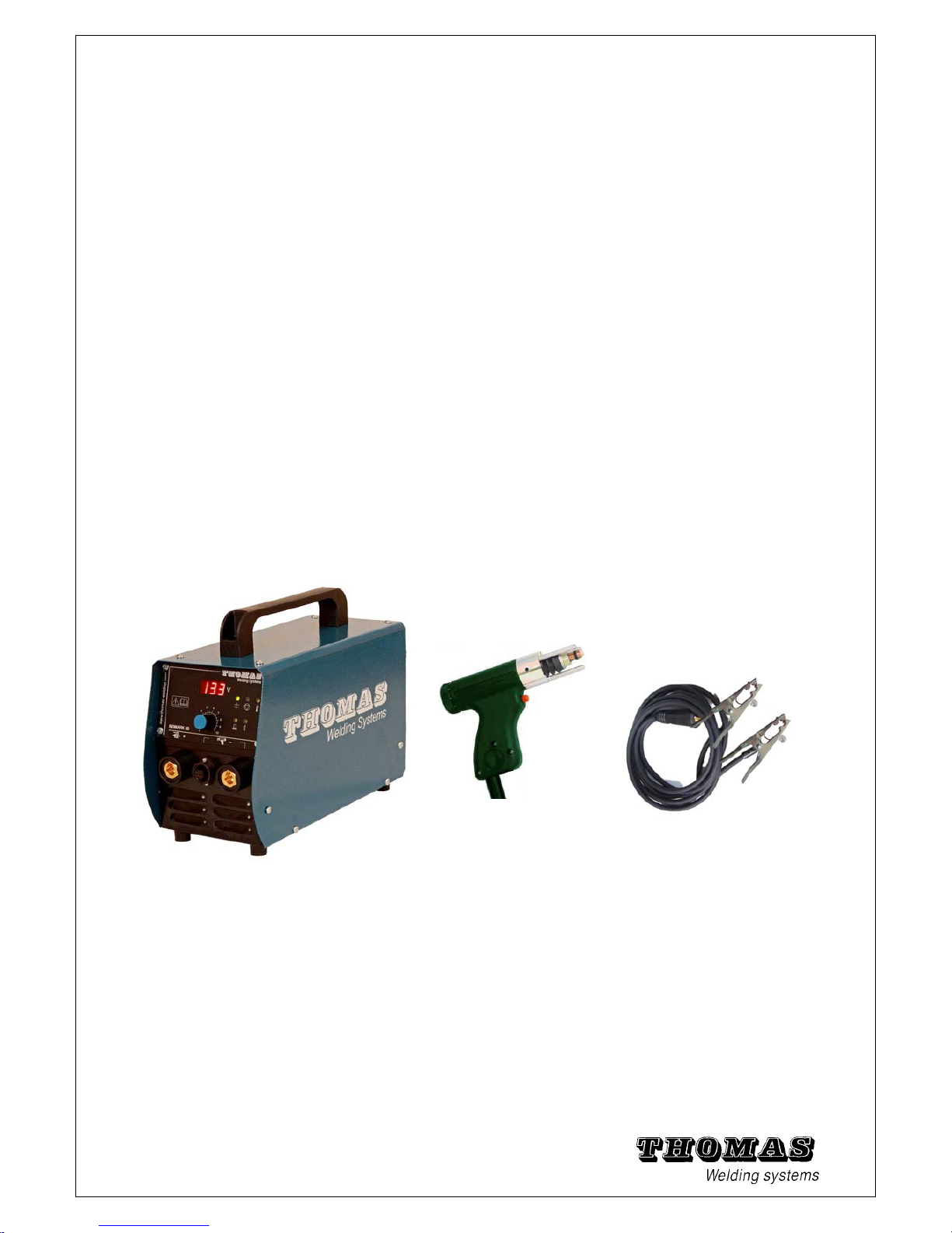
1.2 Components of the stud welding system
The stud welding system consists of the
power unit (type NOMARK 65/ 99), welding gun ,(C0), Ground cable and chuck
NOMARK 65 / 99 C0 welding gun Double ground clamp
Fig. 1 - 1 Power unit and stud welding gun
1) Power unit NOMARK 65 + C0 ( welding gun for contact welding)
2) Power unit NOMARK 99 + C0 ( welding gun for contact welding)
Both welding units can weld normal welding studs. They are equipped with studs manually.
Volt
4
5
6
3
Page 8
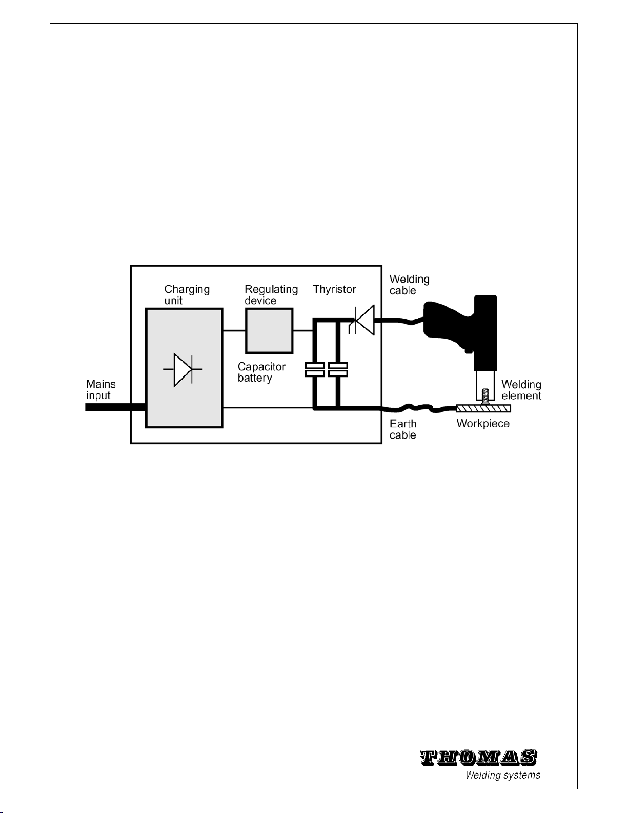
1.3 Functional principle of the stud welding system
Stud welding systems are used to weld metal welding studs (e.g.
threaded studs) on to weldable metal workpiece surfaces.
The power unit NOMARK 65/99 is a mobile welding unit developed by
THOMAS that sets new standards in stud welding technology with
its compact construction.
It works by the principle of capacitor discharge.
Together with a manually equipped welding gun of the type C0 (contact
welding gun) , it can weld normal welding studs with ignition tips.
The welding energy required is delivered by the power unit, which
charges a capacitor battery via a regulator circuit. The welding
current is then activated by a power SCR. The electric circuit is
closed by the welding gun, stud, workpiece and earth cable.
Fig. 1 - 2 Functional principle of the electric control system
7
Page 9
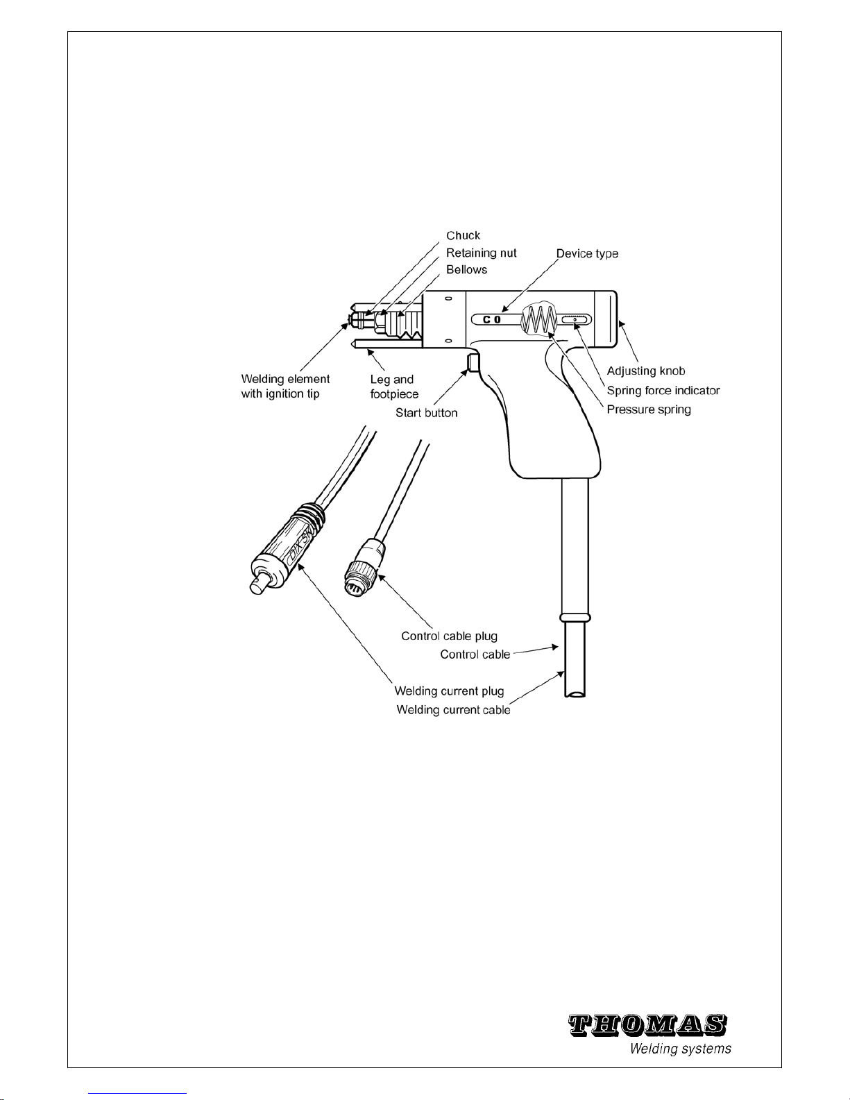
1.4 Stud welding gun C0
Field of application
The C0 is a contact welding gun for welding studs with ignition
tips. The welding elements should preferably be of
steel and stainless steel. Brass or Aluminium studs can also be processed
with limitations.
Owing to the somewhat longer welding time (compared to gap
welding) and deeper penetration, the C0 is especially suitable for lightly galvanised steel
.
Fig. 1 - 3 Contact welding gun C0
See chapter 5.6 for technical specifications and chapter 5.8 for individual part
drawings and replacement part numbers.
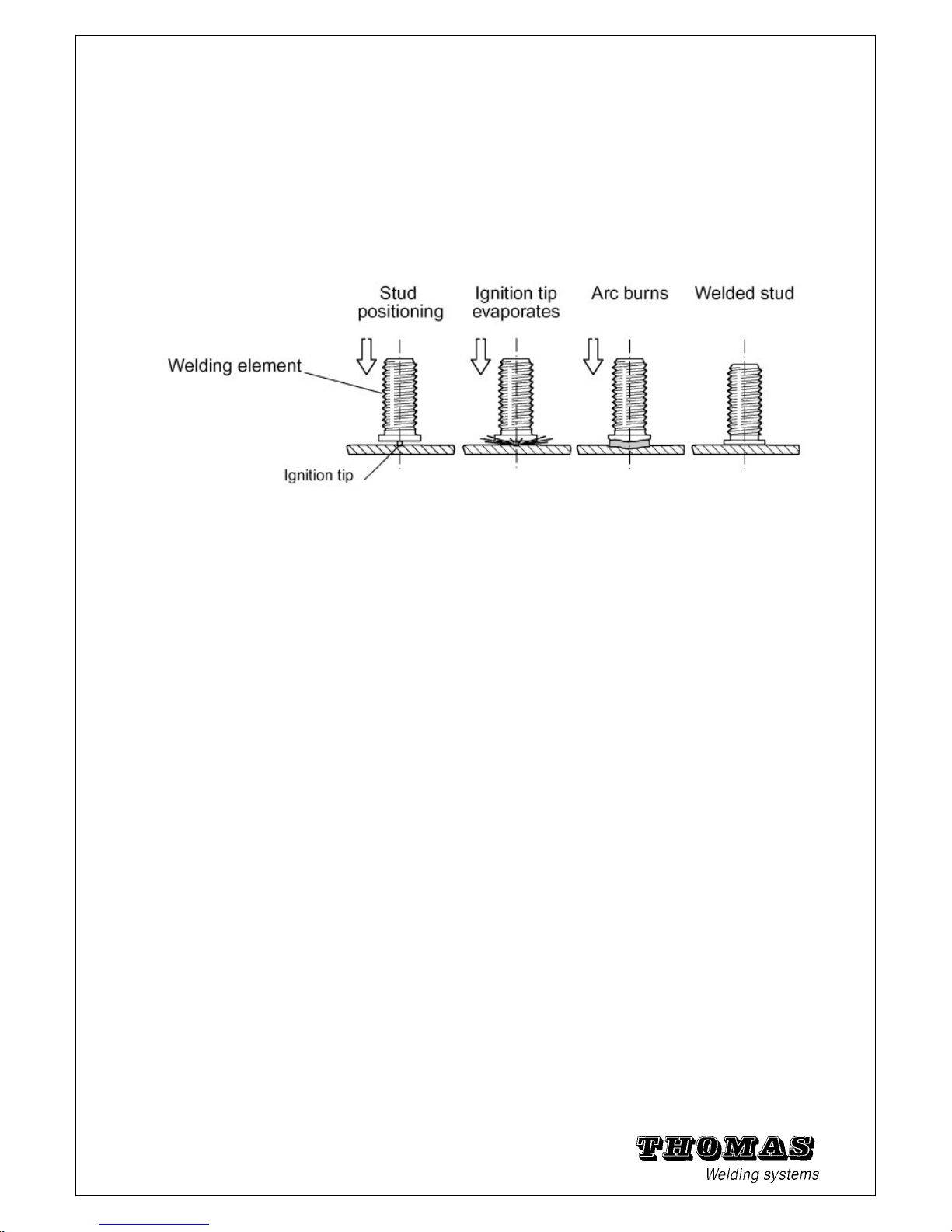
Method
A welding element is first pushed into the Chuck of the welding
gun. The ignition tip of the element is then placed down vertically
at the required point on the workpiece and the gun pressed down
until all positioning feet touch the workpiece (this pushes the
plunger against the pressure spring).
The welding current is then switched on and the welding process
started by pressing the start button. The ignition tip evaporates
and generates an arc, which melts the face of the stud and the
8
workpiece.
Page 10
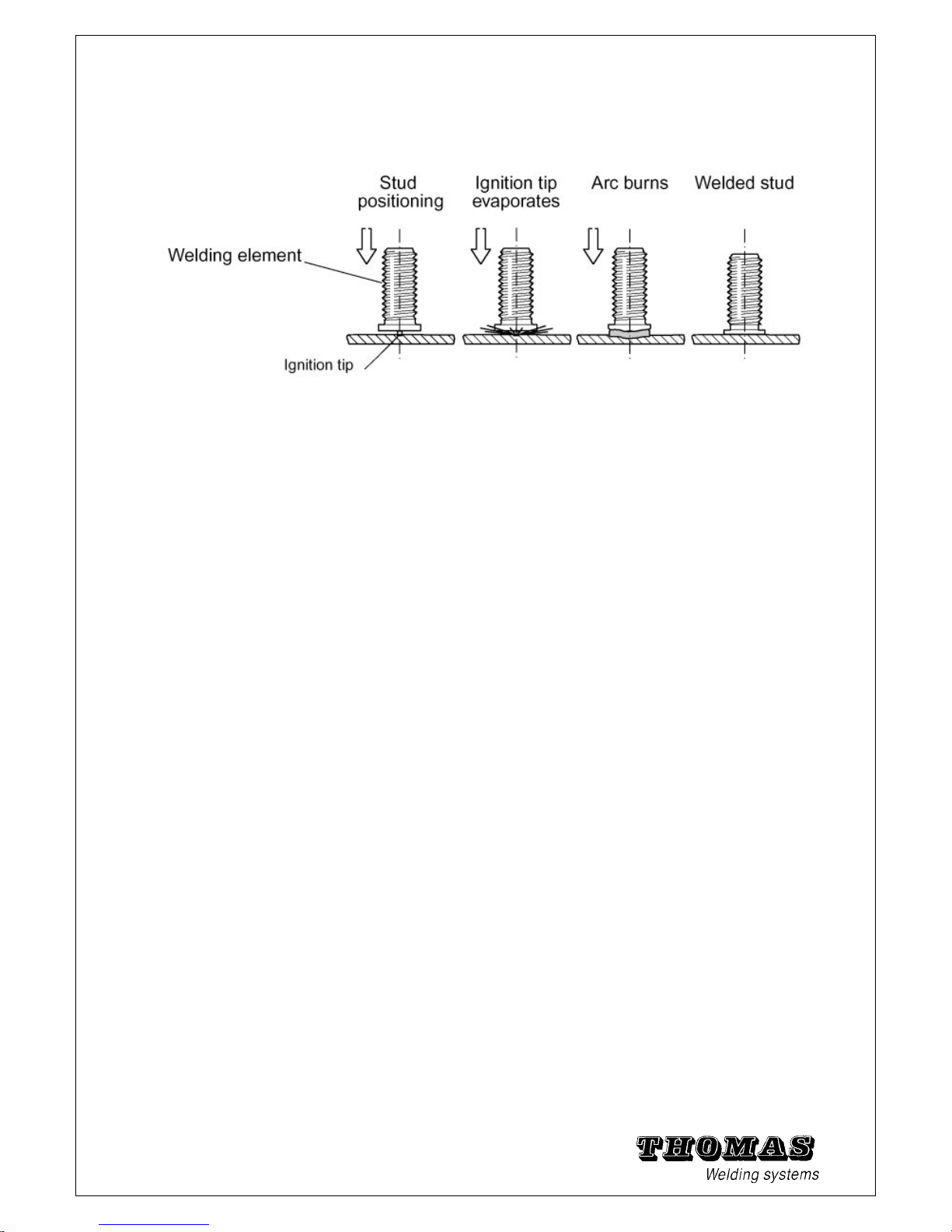
The pre-stressed pressure spring then forces the welding element
into the weld pool and the arc is extinguished. The capacitors are
discharged completely. The weld pool solidifies.
This welding process lasts about 1.5 to 3.0 ms.
The welding gun can be pulled off the welding element vertically
directly afterwards and fitted with a new one.
.
Fig. 1 - 4 Contact stud welding sequence
Note:
A threaded stud was chosen as welding element in the figure above.
Other welding studs equipped with ignition tip are shown in chapter 1.8
9
Page 11
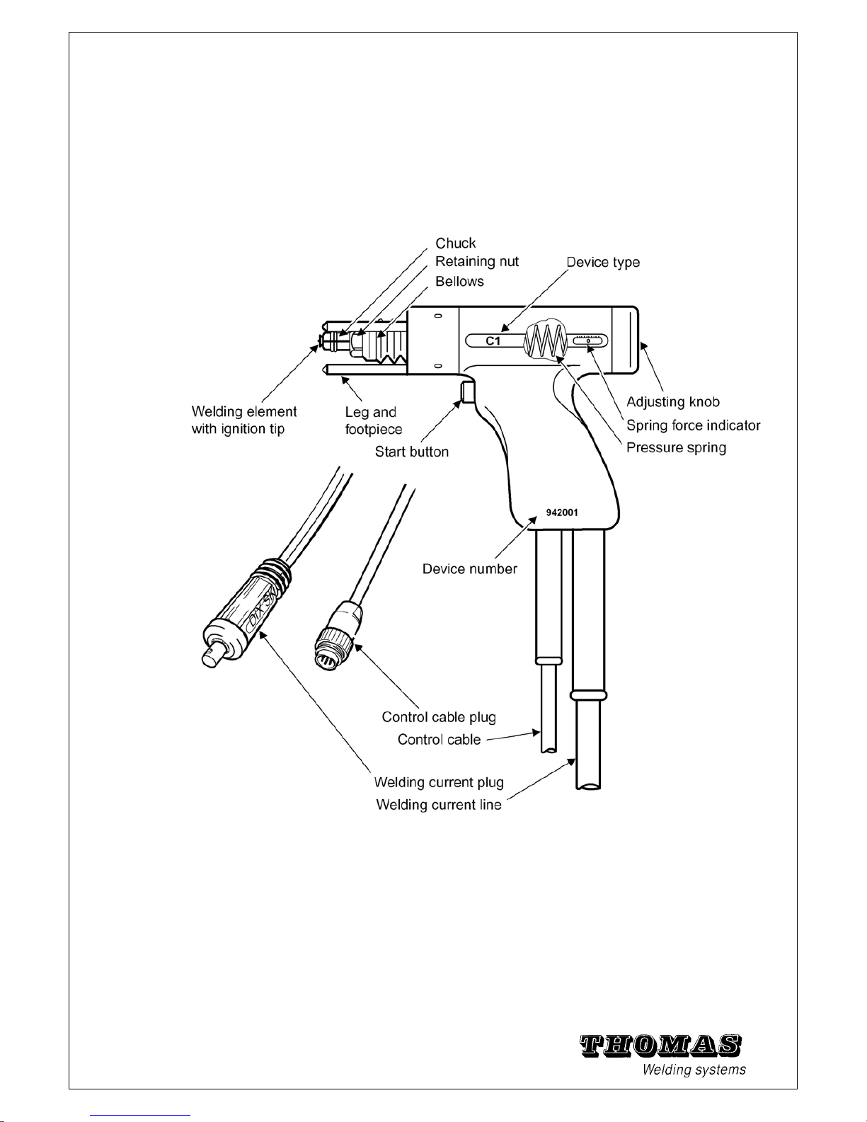
1.5 Stud welding gun C1
Field of application
The C1 is a contact welding gun for welding studs with ignition
tips. The welding elements should preferably be of
steel and stainless steel. Brass or Aluminium studs can also be processed
with limitations.
Owing to the somewhat longer welding time (compared to gap
welding) and deeper penetration, the C1 is especially suitable for lightly galvanised steel
.
Fig. 1 - 5 Contact welding gun C1
See chapter 5.6 for technical specifications and chapter 5.8 for individual part
drawings and replacement part numbers.
Method
A welding element is first pushed into the Chuck of the welding
gun. The ignition tip of the element is then placed down vertically
10
at the required point on the workpiece and the gun pressed down
Page 12
until all positioning feet touch the workpiece (this pushes the
plunger against the pressure spring).
The welding current is then switched on and the welding process
started by pressing the start button. The ignition tip evaporates
and generates an arc, which melts the face of the stud and the
workpiece.
The pre-stressed pressure spring then forces the welding element
into the weld pool and the arc is extinguished. The capacitors are
discharged completely. The weld pool solidifies.
This welding process lasts about 1.5 to 3.0 ms.
The welding gun can be pulled off the welding element vertically
directly afterwards and fitted with a new one.
.
Fig. 1 - 6 Contact stud welding sequence
Note:
A threaded stud was chosen as welding element in the figure above.
11
Other welding studs equipped with ignition tip are shown in chapter 1.8
Page 13
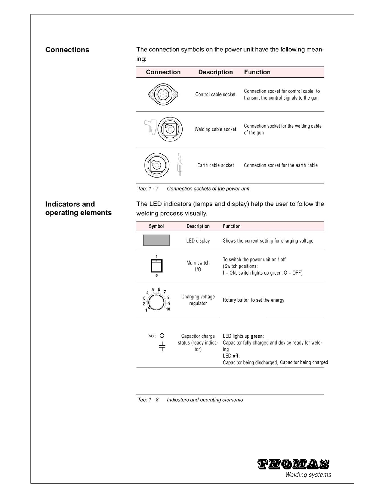
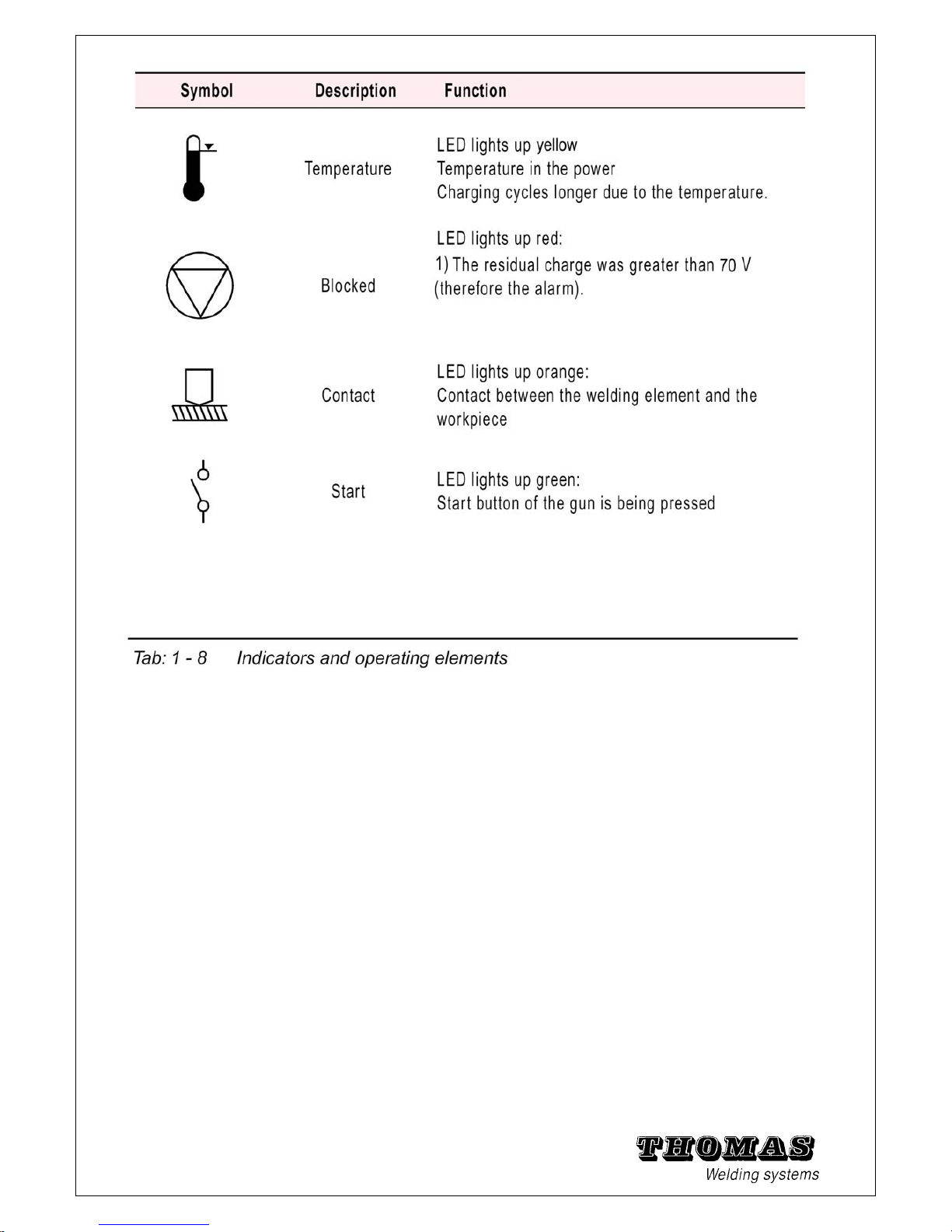
1.6 Meaning and description of symbols
12
Page 14
Start check:
• The following must light up when the power unit has been
switched on:
the main switch, the display (shows the setting for charging voltage)
Note:
• The LED for connection of a gun with hoisting magnet has no
function when the gun C0 is being used.
• Hold the gun with stud against the workpiece: the contact LED
must light up (when earth cable – on both sides – and welding cable connected).
• Hold the gun in the air and press the start button: the start LED
must light up.
• Otherwise no further LEDs should light up.
Troubleshooting
See Troubleshooting chapter 5.1 Troubleshooting.
13
Page 15

1.7 Other descriptions
Ignition tip The power unit NOMARK 65/99 and connected stud welding gun work by
the tip ignition welding method.
In order to ignite an arc and therefore to generate a weld pool,
every stud must have an ignition tip.
Fan To avoid unnecessary soiling, the fan is only switched on when a
high temperature is reached.
Inert gas Inert gas is seldom used in tip ignition welding because the short
welding time gives little time for oxidation.
1.8 Welding elements (studs)
Depending on how the welding gun is equipped, threaded studs,
internal thread bushes and pins (in accordance with DIN 32 501)
of various sizes and materials can be welded if they have an ignition tip.
Fig. 1 - 9 Examples of different types of welding elements
The following conditions must be observed:
• The diameter of the welding element must be <= 10.
• Length of welding studs : from 6 to 40 mm with standard components.
For studs longer than 40 mm, an intermediate ring must be used.
• Length of welding pins : from 6 to 100 mm with standard components.
• A suitable chuck must be selected for every welding element.
Note:
14
Please contact THOMAS regarding different Chuck shapes and sizes.
See chapter 5.10 for standard chucks
Page 16
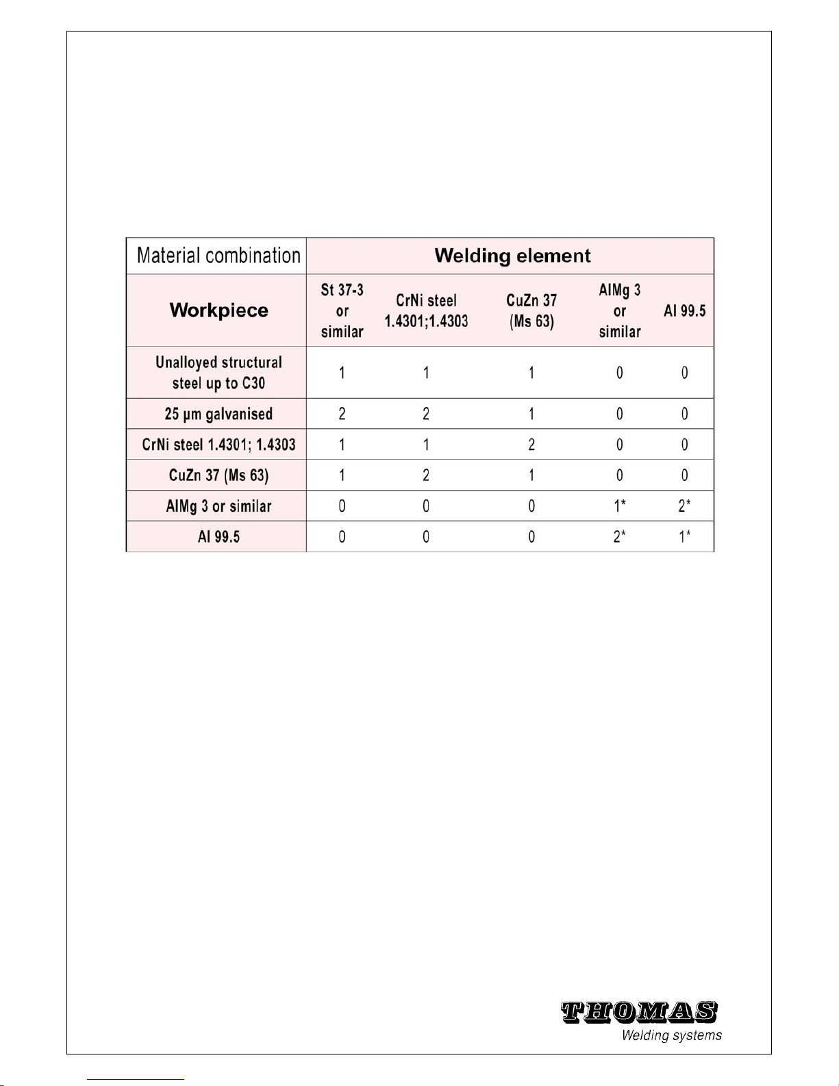
1.9 Material combinations
The weldability of workpiece and welding element materials is defined as follows:
1 = weldable 2 = limited weldability 0 = not weldable/ not tested
* = limited weldability with contact welding gun
Contact and gap welding
Tab: 1 - 10 Suitability of material combinations for tip ignition welding
Note:
Your THOMAS specialist advisor will be glad to advise you in
the case of material combinations not listed in this table.
15
Page 17
16
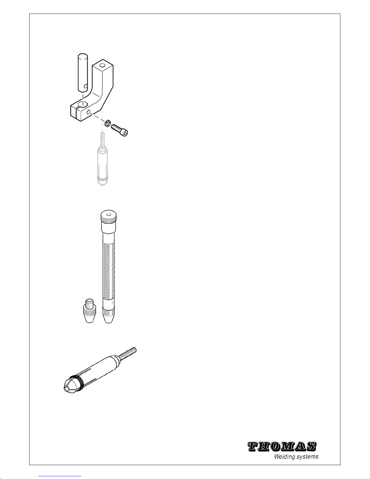
1.14 Angle bracket
With the angle bracket you can approach a right-angled
surface to up to 8 mm with the gun and weld studs (order
no. see chapter 5.10).
1.15 Bending device
The bending device is used in impact bending tests (see
chapter 4.7).
It is manufactured according to DIN 0905 Part 2. The five
inserts must be ordered individually (order nos. see chapter
5.10).
1.16 Chucks (standard)
These chucks are used for threaded studs and un-
threaded studs (order nos. see chapter 5.10).
Page 18
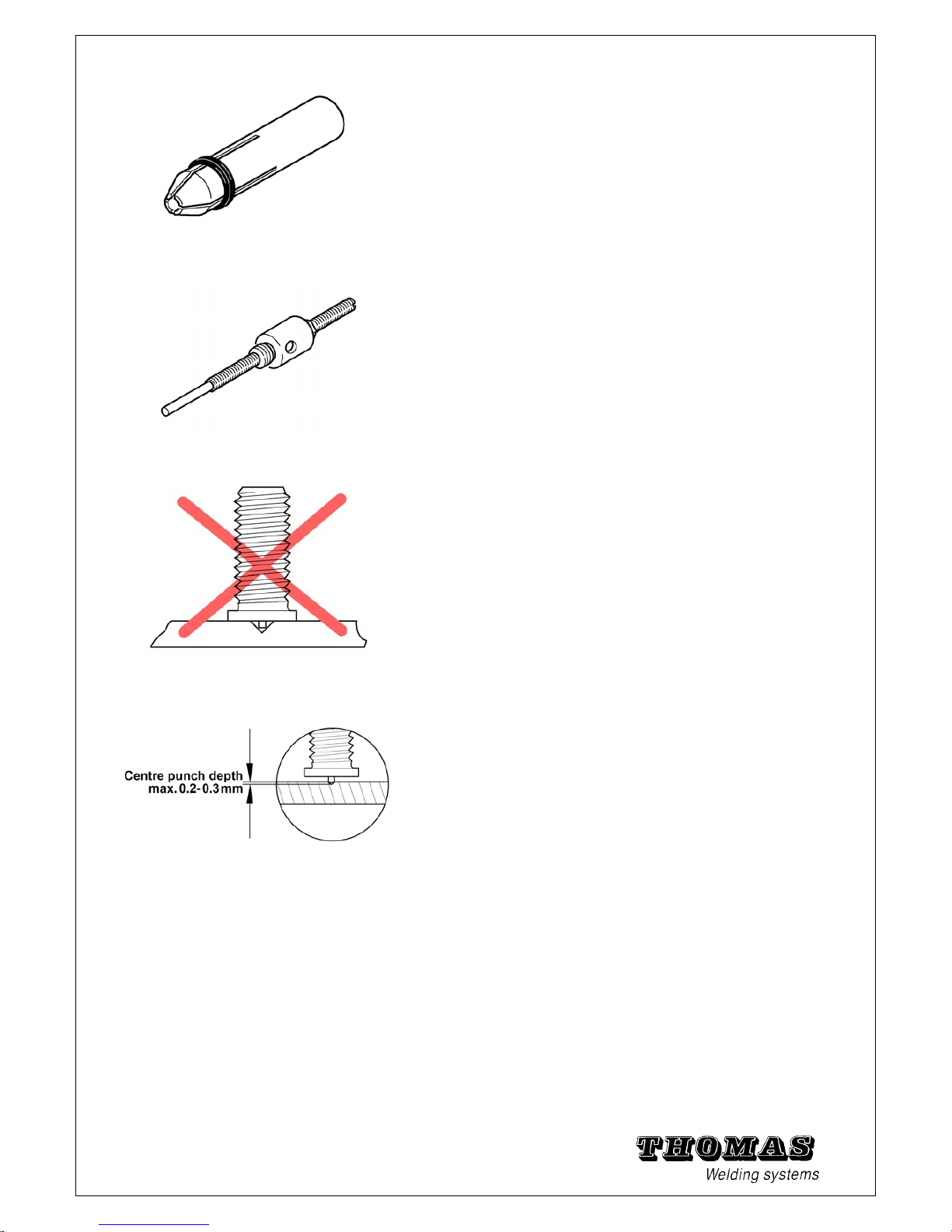
1.17 Chucks (for insulation pins)
These chucks are used for insulating nails and pins
(order nos. see chapter 5.10).
1.18 Chuck extension
The Chuck extension is only used when using a centring
device
(see chapter 1.10; order nos. see chapter 5.10).
1.20 Welding on centre punches
Welding elements with ignition tip can be positioned for
pattern welding exactly on centre punches or scribed lines.
Since the welding process is started by the ignition tip,
marking must be performed carefully.
The arc cannot ignite on a centre punch struck too deeply.
Should it nevertheless ignite, then the strength of the weld
is questionable.
Therefore make sure that the depth of the centre punch
does not exceed 0.3 mm.
Note: You can rule out this uncertainty by using a so-called
automatic
punch (order no. see chapter 5.10).
17
Page 19

2 Work safety and rights
2.1 Safety symbols
2.2 Safety information
2.3 Proper use
2.4 Guarantee and liability
2.5 Copyright
2.6 EC Declaration of conformity
18
Page 20
19
Page 21
20
Page 22
21
Page 23
22
Page 24

23
Page 25

24
Page 26

25
Page 27
26
Page 28

27
Page 29

28
Page 30

29
Page 31

15th October 2012
DECLARATION OF CONFORMITY
We, THOMAS WELDING SYSTEMS SA, Zone Industrielle, 3
ème
RUE, B. 6040 JUMET
(BELGIUM) declare, solely that the product
NOMARK 65 / NOMARK 99
mentioned in this declaration, complies with the following standards and / or normative documents :
Low Voltage EN 60974-1
EMC EN 50199
and thus declare that the mentioned product comply to the essentials requirements of the LVD directive
2006/95/EEC.
Pascal THOMAS
30
Page 32

3 Delivery ... Installation
3.1 Extent of delivery
3.2 Receiving inspection
3.3 Storage
3.4 Transport
3.5 Place of use
3.6 Erection
31
3.7 Power connection
Page 33

3.1 Extent of delivery
The extent of delivery for the power unit NOMARK 65/99 contains the following
components and accessories:
• 1 power unit NOMARK 65/99
• 1 welding gun C0 or C1
• 1 earth cable with two earth clamps.
• Accessories set including :
1 socket spanner (width across flats 17 mm)
1 welding gun Chuck M3
1 welding gun Chuck M4
1 welding gun Chuck M5
1 welding gun Chuck M6
1 welding gun Chuck M8
• 1 set of operating instructions for NOMARK 65/99 with C0/C1 gun
Note:
The article numbers for orders are to be found from chapter 5.4 on.
The accessories are only free of charge when ordering a complete set.
3.2 Receiving inspection
The power unit was checked for working order before dispatch.
It must be checked on delivery for damage and completeness of
the parts contained in the extent of delivery.
The manufacturer or responsible haulage company must be notified
immediately of any transport damage and/or missing parts.
3.3 Storage
If the power unit NOMARK 65/99 is not put into operation directly after
delivery, it must be stored in a secure place.
The complete power unit must be protected adequately against
dust and moisture.
To preserve the lifetime of the capacitors, the power unit must be
switched on for about an hour every six weeks, with the charging
voltage being raised gradually from 1 to 10. Then turn the charging
voltage regulator back to position 1.
3.4 Transport
To avoid damaging the power unit, the NOMARK 65/99 should only be
32
transported using the carrying handle provided.
Page 34

3.5 Place of use
Use of the power unit NOMARK 65/99 is restricted to closed industrial
and commercial rooms.
When using the system in residential and business environments
the operator must take special measures to ensure that the electromagnetic
fields arising during welding do not represent a danger to people and property.
Danger:
• Caution! Danger to life! Wearers of cardiac pacemakers must
keep clear of the vicinity of stud welding systems.
• The electromagnetic fields arising during welding can disrupt or
damage other electrical or electronic equipment. For this reason a
minimum distance of 10 m must be kept between the welding system
and other electrical and electronic equipment.
• Do not operate the power unit in the vicinity of data storage media.
Their contents may be deleted.
• Use of the power unit in rooms where there is a danger of fire or
explosions or in damp rooms is strictly forbidden.
• Solvents containing chlorine must be removed from the welding
area. They may not be exposed to the arcs of the welding system.
3.6 Erection
Place the power unit on a horizontal, vibration-free and non-slip surface.
The bearing strength of the surface must be at least twice
the weight of the power unit.
Due to the design and power of the NOMARK 65/99, thermal stresses occur
in the housing. These temperatures are reduced by a fan.
Make sure the air inlet is always kept free.
To keep the temperature level low, the fan is switched on at a device
temperature of 60°C.
To ensure unhindered heat exchange with the surroundings, the
power unit must be kept at least 1 m away from other sources of heat.
3.7 Power connection
The power cable with plug is located at the back of the unit.
The following mains ratings must be observed:
• Mains voltage: 230V (factory setting)
• Mains frequency: 50Hz (factory setting)
• Mains fuse: min. 10A (slow-blow)
The control voltage for all welding gun functions is supplied by the
power unit.
Note: If the standard factory setting of 230 V/ 50 Hz is to be
changed to 115 V/60 Hz, you must contact TWS.
Warning: Switch off the power unit and pull out the mains plug
before opening.
The following safety precautions must be taken before the power
unit is connected to the mains power supply:
• Only use mains power sockets with tested protective conductor
function. This test must be performed by an electrician.
• Compare the values of the mains power supply with the specifications
on the rating plate. If they do not correspond, consult an
electrician to take appropriate steps (see above).
When the above precautions have been taken, the power unit can
be connected to the mains power supply.
33
Page 35

4 Operation
4.1 Connections of the power unit
4.2 Chuck preparation
4.3 Adjusting the C0
4.5 Tips for good welding results
4.6 Work procedure during welding
34
4.7 Testing the weld
Page 36

All connection sockets and operating elements are arranged
freely accessible on the front panel of the power unit NOMARK 65/99.
The mains power switch is located at the back of the unit
35
Page 37

36
4.1 Connections of the power unit
The power unit is designed for connection of the welding
gun C0 or C1.
.
Caution: If welding guns from other manufacturers are
connected to the power unit, no guarantee regarding
safety and functionality of the welding system can be
given. TWS accepts no liability for damage caused by the
use of guns from other manufacturers.
Warning: The power unit NOMARK 65/99 must be
switched off before carrying out connection work. The
main switch must be in the position "0".
Lay the cable such that it does not represent a tripping
danger.
4.1.1 Connecting the
earth cable
Connect the earth cable directly to the workpiece or to the
workpiece holder (welding bench, welding grate, etc.)
provided.
Note: Steel structures, pipes, etc. may not be used as
current conductor if they are not themselves the workpiece
that is to be welded.
Warning: Observe all applicable safety regulations and
take
suitable safety precautions.
Note: The welding current circuit may not be earthed.
Exception:
the workpiece itself is earthed by necessity (steel
structure, shipbuilding, pipes, etc.).
• The welding site must lie between the two earth clips:
do not place the two earth clips too close to the welding
site and – if possible – position them symmetrically and
equidistant to the welding site. In this way you avoid a
magnetic arc blowing action (sideways deflection of the
arc).
• Plug the earth cable plug into the connection socket
marked .
• Fasten the earth cable plug firmly in place by turning it
strongly clockwise.
Page 38

37
4.1.2 Connecting the
welding gun
Caution:
Make sure the power unit is switched off.
• Plug the welding cable plug into the connection socket marked .
• Fasten the welding cable plug firmly in place by turning it
strongly clockwise.
• Plug the control cable plug into the corresponding connection
socket and lock it in place.
Page 39

38
4.2 Chuck preparation
The Chuck is selected in dependence on the welding
element
(welding stud). The extent of delivery of the stud welding
system
contains chucks from M3 to M8.
The suitable Chuck must then be adjusted to the length of
the
welding element
.
Note: Chucksare wearing parts and should therefore
always be
kept in stock and ordered in time (see chapter 5.10).
Procedure
1. Select a Chuck fitting the diameter and form of the
welding element.
2. Depending on the length of the welding element, fit the
striking
pin in the Chuck as follows:
a) Welding elements up to 20 mm in length:
The unthreaded part of the striking pin is located
inside the chuck.
b) Welding elements from 20 to 40 mm in length:
The unthreaded part of the striking pin is located
outside the chuck.
c) Welding elements over 40 mm in length:
An intermediate ring (accessory part) is additionally
required (see
chapter 1.19 and chapter 5.4).
3. Equip the Chuck with the welding element.
4. Turn the striking pin until the distance between locknut
and stud face is:
when using the C0: 51 mm (to max. 53 mm)
.
Note: Add 12.5 mm when using a Chuck extension!
5. Warning: Switch off the power unit before inserting the
Chuck (to rule out any eventualities).
Page 40

39
Caution:
The retaining nut may not be tightened when there is
no Chuck in the welding gun.
6. Loosen the retaining nut (if it is tight) by turning 90° with the
socket spanner.
7. Insert the Chuck to the stop in the plunger of the welding gun.
8. Then tighten the retaining nut firmly.
Caution: Make sure that the bellows is positioned correctly on
the retaining nut.
Page 41

40
4.3 Adjusting the C0 and C1 gun
The electrical and mechanical welding parameters are set
at the
power unit and on the welding gun.
Welding time
• The welding time depends on the stud speed. It is
adjusted indirectly
via the spring force. The greater the spring force is, the
higher the speed of the welding element and therefore the
shorter
the welding time.
The spring force is set with the adjusting knob (
Turning clockwise:
The spring force is increased, thereby reducing the
welding time.
Turning anticlockwise:
The spring force is reduced, thereby increasing the
welding time.
Note: To prevent damage to the adjusting mechanism,
never use force to turn the adjusting knob into its end
positions.
Procedure
• Find your material combination and the diameter of the welding
element in
table 4 - 1.
• Turn the adjusting knob until the spring force indicator on the
welding gun shows the value from the table.
Tab: 4 - 1 Recommended spring force [mm] for contact stud welding gun C0/ C1
* Aluminium joints can only be welded with the contact welding gun with limitations
Page 42

Charge voltage
The welding current strength is regulated via the charge voltage
of the power unit (see
table 4 - 2).
To set the charge voltage, turn the power regulator (see chapter
1.6
) until the digital display shows the voltage value required.
Tab: 4 - 2 Recommended charge voltage [V] in the power unit NOMARK 65/99
*
* Aluminium joints can only be welded with the contact welding gun with limitations
Note:
The settings in the tables are approximate values only,
attained
under optimised welding conditions.
The settings of the power unit and welding gun must be adjusted
exactly to the respective welding job (e.g. to the base metal) in
dependence on the welding result (see also
chapter 4.7 Testing the
weld
).
41
Page 43

4.5 Tips for good welding results
The following tips contain important information on how to achieve
good weld joints.
1. The welding elements and workpieces must be weldable. Only
use material combinations specified in these operating instructions
(otherwise suitable tests must be carried out beforehand to
confirm the necessary quality features).
2. Make sure that the maximum roughness of the welding zone does
not exceed 80 µm.
3. The welding zone should be metallically bright:
Workpieces of aluminium or with aluminium coating may only be
cleaned with a rust-free wire brush.
Carefully remove all soiling like rust, scale, paint, moisture,
grease and oil.
Strip anodised workpiece surfaces with a caustic soda lye or grind
them clean.
4. The welding site must be designed so that there is always a surface
of at least Ø 40 mm available to receive the positioning feet.
When using centring tubes or similar, at least Ø 20 mm.
5. Make sure the workpiece is supported such that it is free of vibrations.
This is especially important in the case of large and thin walled
workpieces.
6. Always lay the welding and earth cables free of loops. In this way
electromagnetic influences can largely be avoided.
7. Fasten the earth clips symmetrically to the welding site and not
too close to it. In this way flaws in the weld quality caused by arc
blowing can be avoided.
8. Make sure there is a good transfer of current (low resistance) at
all contact points in the welding circuit (welding cable connections,
chuck, earth cable connection, earth clips).
9. Observe the necessary settings on the welding gun and power
unit for your welding job.
10. The welding gun and workpiece may not be moved during the
welding process.
11. Always pull the gun off the welding element vertically. This prevents
overstretching of the Chuck blades.
12. Avoid welding on one workpiece with more than one welding system
at the same time (possible influence on the arcs).
13. In order to check that the settings are correct, a number of trial
42
welds should always be performed before commencing work. The
Page 44

quality of the welding results must be checked.
14. Check the clamping force of the Chuck blades from time to time
and bend them together a little if necessary. This increases the
lifetime of the chuck.
43
4.6 Work procedure during welding
Before commencing welding work make sure that the welding
gun
and power unit are connected correctly (chapter 4.1) and the
set
values correspond to the welding job.
Observe the following safety information.
Warning: All persons working with the welding system must
observe
the safety information in chapter 2 before commencing work.
When the start button is pressed, the Chuck and the welding
element
carry current for approx. 10 ms. These parts may not be
touched
during welding!
Preparing the welding gun C0 / C1:
• Equip the gun with a suitable chuck.
• Set the "spring force" (for C0) according to the
instructions (chapter 4.3 and chapter 4.4).
• Insert a welding element in the chuck.
Preparing the power unit NOMARK 65/99:
• Switch on the power unit. Carry out the start check (see
page 13).
• Set the charge voltage according to the approximate
values specified in chapter 4.3 and chapter 4.4.
The setting can be read on the digital display.
• A number of trial welds must be carried out (with the
specified values) to find the optimum setting.
Page 45

44
Work procedure:
1. If not already done, insert a welding element in the
chuck. Position the welding gun on the welding spot
vertically. The contact LED lights up.
2. Press the welding gun vertically (90°) against the
workpiece surface
with both hands.
3. Hold the welding gun steady and press the start button.
The welding
process is started. At the same time the start LED lights up
A trigger block prevents the welded welding element from
being welded again. The power unit remains discharged.
4. After welding remove the welding gun vertically from the
welded welding element.
The LED "contact" go out and the power unit charges the
capacitors for the next welding operation.
5. Check the welding result in accordance with chapter 4.7.
If the welding result is not satisfactory, the settings must be
optimised.
Warning: After completing welding work or in the case of
longer breaks in welding work disconnect the machine from
the mains power supply and secure it against unauthorised
use.
Page 46

45
4.7 Testing the weld
Testing of the weld in continuous production monitoring is
restricted to a visual inspection of the welded stud. Further
testing is possible, but complex. Consult your TWS specialist
advisor or study DVS Guideline*) 0905 Part 2 in this regard.
If a weld is thought to be defective, an impact bending test
must be carried out on the welding studs concerned according
to section 4.7.2.
*) DVS Guideline 0905 Part 2: Ensuring the quality of stud welds "Stud
welding with tip ignition"
**) DIN 8563 Part 10: Ensuring the quality of stud welds (edition:
December 1984)
4.7.1 Visual inspection
Every welded welding element must be checked visually.
Besides
assessing the weld bead for form, size and appearance, you
should also check the nominal length of the welded stud.
1. Good welding:
The bead is closed and has a shiny surface. There is no visible
undercutting at the bottom of the welding element. Small
notches
between weld bead and stud shaft are unavoidable and can be
ignored.
2. Welding too hot:
Deep notches can be seen between weld bead and stud shaft.
Due to the strong melting, the melt zone at the stud middle is
recessed.
The excess weld metal was flung out of the welding zone.
(Spring force or lift too low.)
3. Welding too cold:
The form and height of the weld bead are irregular. Distinct
undercutting
can be seen at the stud edge. Due to the low energy, the
melt zone under the complete stud cross-section is very flat.
(Spring force or lift too high.)
Page 47

4. Welding too irregular:
The weld bead is asymmetrical (as a result of magnetic arc
blowing
action) and the stud edge is undercut on one side. (Possibly
change earth clip positions.)
4.7.2 Impact bending test
The impact bending test is one of the most common test methods
to check welding parameters and to identify defective welds.
If a weld joint is thought to be defective or the fusion length of the
stud is too short, the impact bending test must be carried out as follows:
Bend the welding element by 60° with a hammer or bending device.
This stresses the weld joint in tension, pressure and bending
by an undefined amount.
• The impact bending test is deemed as passed if there are no
cracks to be seen in the welding zone.
• If the welding element is torn out of the base metal (a recess is
formed in the workpiece), the weldability of the materials is
deemed proven.
• If the welding element breaks off in the welding zone, you must
check whether:
- both materials are weldable,
- the material combinations are weldable,
- the ignition tip is in order,
- the settings on the welding gun and power unit are correct and
the welding gun or power unit is defective.
-
If these requirements are not met, an impact bending test must
also be carried out on the three previous and three next welds.
Warning:
Welding work may only be continued when satisfactory
test results are obtained.
46
Page 48

5 Maintenance
5.1 Troubleshooting
5.2 Care and cleaning
5.3 Maintenance intervals
5.4 Conversion and wearing parts
5.5 Fuse elements
5.6 Technical specifications
5.7 Replacement parts NOMARK 65/99
5.8 Replacement parts C0
5.9 Block circuit diagram
5.10 Spare parts and welding accessories
47
5.11 Blank page for notes
Page 49

5.1 Troubleshooting
In the event of a malfunction proceed as follows:
1. Switch off the power unit.
2. Unscrew the control, earth and welding cables from the
power unit.
3. Switch on the power unit.
4. If in addition to the main switch, the mains power LED, the
capacitors charge status LED and the display any other LED
then also lights up, switch off the power unit again and contact
TWS.
Warning: In the event of a system malfunction the power unit
must be switched off, disconnected from the mains and
secured
to that it cannot be switched on again.
If no other LED lights up, you can take the following
remedial measures:
Warning:
Faults in the power unit NOMARK 65/99 requiring the housing
to be opened may only be repaired by authorised electricians!
Faults in the welding gun requiring only replacement of
mechanical replacement parts can be repaired by skilled
personnel with the aid of the exploded view (chapter 5.8 and
chapter 5.9).
After repair a function test of the protective circuits must be
carried out by an electrician.
Only replacement parts specified in the corresponding part lists
may be used to replace parts!
Malfunctions that cannot be repaired by the remedial measures
listed below may only be repaired by TWS or authorised repair
technicians.
1. First carry out the start check (page 13).
If the test results is negative, continue with the relevant point in
table 5 - 1.
48
Page 50

Indicators Situation Cause Remedy
2. Main switch does not
light up although it is
switched on
• NOMARK not connected
Fault in:
• Main switch or lamp
• Power cable
• Mains power plug
• Mains fuse
• Connect NOMARK and switch
on!
Check*) and replace if
necessary*):
• Main switch or lamp
• Power cable with plug
• Mains fuse (in switch box)
3. Main switch lights up,
Display does not light up
Fuse defective Replace fuse in NOMARK
65/99*)
(see chapter 5.5)
4. Main switch lights up,
Display does not light up
Fuse defective Replace fuse*)
(see chapter 5.5)
5. G1 is connected,
but LED "magnet"
does not light up
Control cable damaged
(e.g. loose contact); hoisting
magnet in gun defective
Connect another gun and check
whether the LED then lights up;
replace cable or hoisting magnet
if
necessary*)
6. No G1 connected,
but LED "magnet"
still lights up
Fault in power unit Shut down NOMARK and mark
as
defective so that it is not switched
on again; notify TWS
after sales service
7. LED "blocked"
lights up
• Malfunction
• Fault in power unit
• Switch NOMARK off and then
on
again. If LED does not light up
again, continue working.
• Shut down NOMARK and mark
as
defective so that it is not switched
on again; notify TWS
after sales service
9. Ready LED does not
light up
Fuse defective Replace fuse*)
(see chapter 5.5)
10. Contact LED does
not light up on contact
with the workpiece
• No earth or welding cable
connected
• One of the cables is
defective
• NOMARK 65/99 defective
• Connect earth, control and
welding cables to NOMARK
• Replace cable if necessary
• Notify TWS aftersales
service
11. Start LED does not
light up although the
start button is being
pressed
• Control cable not
connected to NOMARK 65/99
• Control cable defective
• gun defective
• NOMARK 65/99 defective
• Connect and fix cable
• Replace cable if necessary
• Connect another gun and test
LED again
• Notify TWS after sales
service
12. Start LED lights up
although the start
button is not being
pressed
• Short circuit in control
cable
• Start button defective
• Replace control cable or
start button if necessary (see
chapter 5.8 or chapter 5.9)
*) Check only by electricians!
Tab: 5 - 1 Troubleshooting using LED indicators
49
Page 51

Indicators Error number Cause Remedy
Voltmeter
Display
E 1
Gun trigger pressed at machine
switch ON
Check gun trigger
E71
Weld SCR defect
E72
Capacitors are not charging Check fuse or overheat of
the machine
E73
Capacitors are still charged when
unit is switched ON
E74
Main relay defect
E75
Defect charging SCR
E76
Capacitors are not charging during
the test when unit is switched ON
Check fuse or overheat of
the machine
E77
Capacitors are discharging too
fast.
Check Main relay and the
discharge resistances.
E78
No weld (no discharge) - Weld SCR defect.
- Control Board defect
- Bad electrical contact in the
welding circuit (gun/plate)
E79
Capacitors voltage is too high (>
210 v)
Tab: 5 – 1b Troubleshooting using Voltmeter LED display
Malfunction or
change
Situation Cause Remedy
Charging cycle
takes
longer
Temperature NOMARK
is high
Clear air slots of NOMARK 65/99 if
appropriate; keep adequate
distance between NOMARK and
other objects; remove heat sources
from environs; shield
against heat radiation
Welding is not
Started
No welding element in
chuck (LED "contact"
off)
Insert welding element in chuck and
repeat welding
Welding is not
Started
Welding element does
not have
an ignition tip
Insert welding element with ignition
top in Chuck and repeat welding
Welding is not
Started
Control cable defective Check control cable and replace if
necessary
Welding is not
Started
Gun micro switch
defective
Check micro switch and replace if
necessary
Welding is not
started
Control board defective Replace control board*) or notify
TWS Tech after sales service
*) Check only by electricians!
Tab: 5 - 2 Defective welds or malfunctions
Note: Never weld with an overlarge or expanded Chuck because the Chuck will be damaged.
50
• Never weld without stud because the Chuck will then also be damaged.
Page 52
51
Welding result
defective
1.The start check (see page 13) has been carried out (indicators are okay).
2. Defective welding results were achieved:
Situation Cause and remedy
- Defective weld • Set correct charging voltage (see table 4 - 2 and
table 4 - 4)
• Set welding gun (see table 4 - 1 and table 4 - 3
and chapter 4.7)
• General: study and apply chapter 4.3 to chapter
4.7 inclusive
- "Cold weld" • Chuck : clean or replace
• Welding time too short (spring force or lift too
high)
- "Very hot weld" • Welding time too long (spring force or lift too low)
- "Bond weld,
stud does not hold"
• Very strong melting loss, stud does not lift off
♦ Increase spring force or lift significantly, clean or
replace gun plunger
- Stud shaft or stud thread
scorched
• Chuck does not match the welding element
dimensions -> use a suitable chuck
• Chuck has been expanded retighten or
replace (in future pull off the gun vertically from the
welded studs)
- Constantly changing
welding results
• Place gun on workpiece at right angle; replace
positioning feet if necessary
• Gun plunger is stiff ->clean or replace
- Irregular welds • Gun plunger is stiff ->clean or replace
- Arc drop during welding
(no-load welding))
• Clean welding site of oil, grease and other
contamination
• Check workpiece for spring
• Check spring force or lift
• Clean supporting feet or supporting tube
• Optimise earth clip position
- Welding stud crooked • Place gun on workpiece at right angle
• Replace worn or bent positioning feet
• Replace positioning tube
- Welds with distinct
beading
on one side (blowing
action)
Eliminate magnetic arc blowing action by
• changing the position of the welding cable
• changing the position of the earth clips (see fig. 1
- 12)
• bringing in additional plates on iron parts
*) Check only by electricians!
Page 53

52
5.2 Care and cleaning
The stud welding system does not require any special care.
The following cleaning work is nevertheless recommended.
The cleaning intervals depend on the degree of soiling, but
should not exceed max. six months.
Warning: The power unit must be switched off and
disconnected from the mains power supply before cleaning.
Welding gun
• It must be ensured that the handle of the welding gun is
always dry, clean and free of greases and oils.
Caution: No aggressive agents, agents containing alcohol or
in- flammable liquids may be used to clean the welding system.
• Positioning feet and chucks soiled with weld spatter
must be cleaned with a brass wire brush.
Power unit
• The housing must be wiped with a damp cloth. The
rating plate
and safety information must be kept in a legible condition.
Caution: No aggressive agents, agents containing alcohol or
in- flammable liquids may be used to clean the welding system.
• The front panel of the power unit must be cleaned with a
grease dissolving cleaning agent. The LED indicators
must be clearly readable in operation.
Connecting cables
• All connecting cables must be cleaned with a dry cloth.
Scorched sites or mechanical defects can then be
detected more easily. The cables must be replaced if
necessary.
Inside the device
• It might also be necessary to clean the inside of the
device if it is very dirty.
Warning: Only authorised electricians may open the power
unit
and work inside the housing.
The power unit must be switched off, disconnected from the
mains power supply and secured so that it cannot be switched
on again before opening.
• Dirt and contamination inside the power unit like metallic
dust or conductive chips must be sucked off. They may
not be blown out with compressed air!
Warning: After the cleaning work the device must be restored
to and handed over in orderly condition so that – when used
properly in accordance with these instructions – it does not
pose a danger to the user or the environment.
Page 54

5.3 Maintenance intervals
You can avoid malfunctions caused by inadequate maintenance
by adhering to the following maintenance intervals.
The maintenance intervals and instructions specified in the table
below presuppose proper use under normal conditions.
Warning: Maintenance work requiring the power unit NOMARK
65/99 to be opened may only be carried out by authorised
electricians
Maintenanc
e
intervals
Maintenance instructions
Every 8
hours
or daily
• Check the welding cable, earth cable,
control cable and
power cable for external damage – replace
defective cables immediately.
• Check the Chuck (wearing part) for adequate
clamping force and wear; replace if necessary.
• Check the welding cable plugs for firm
connection; tighten if necessary – replace
scorched plugs.
• Check the retaining nut of the gun for firm
seating; tighten if necessary.
• Check the bellows for correct seating and
adjust if necessary – replace if damaged.
• Check the positioning feet for firm seating;
tighten if necessary – replace bent feet.
• Check the gun plunger for ease of movement
– clean with a brass brush.
Every 35
hours
or weekly
• Check connections and operating elements.
• Make sure the LEDs work.
Every 800
hours
or half-yearly
Power unit NOMARK 65/99:
Check for dirt and contamination*) inside the
housing and clean*) if
necessary according to chapter 5.2.
Check all screw connections.
Every two
years
• General inspection of the power unit by repair
technician and electrician.
*) Check only by electricians!
Tab: 5 - 4 Periodic maintenance intervals
53
Page 55

Warning: After the cleaning work the device must be restored to
and handed over in orderly condition so that – when used
properly
in accordance with these instructions – it does not pose a
danger to the user, other people or the environment.
5.4 Fuse elements
To protect against impermissibly high currents, the back of the
power unit is equipped with one fuse to protect the circuits:
• Fuse 10 A / 250 V – Time Long
The mains power socket to which the power unit is connected
should be protected with a fuse of at least 10 A.
Tab: 5 - 14 Fuses in NOMARK 65/99
Fig. 5 - 15 NOMARK 65/99: Back view with fuses
Warning: Always replace defective fuses with like fuses of
identical ratings.
54
Page 56

55
5.5 Technical specifications
Power unit : NOMARK 65 / 99
Welding method tip ignition in contact welding
Input voltage / Frequency NOMARK 65 / 99 (230 V)
230V(±10%) / 50Hz-60Hz
(see chapter 3.7)
NOMARK 65 / 115 V
115V(±10%) / 50Hz-60Hz
(see chapter 3.7)
Mains fuse external NOMARK 65 (230 V) : T 6.3 A
NOMARK 99 (230 V) : T 10 A
NOMARK 65 (115 V) : T 10 A
Charge capacity max NOMARK 65 : 66.000 µF
NOMARK 99 : 99.000 µF
Charge voltage 40 to 200 V, continuously adjustable
Fuses:
Mains voltage 10A / 250V
Cooling fan (AF)
Protective system IP 21
Protection class I (one)
Dimension (l x w x h)
400 mm x 195 mm x 270 (315) mm
Weight NOMARK 66 : 12,5 Kg
NOMARK 99 : 14 kg
Power cable length: 3 m
line cross section: 3 x 2,5 mm2
Earth cable (standard)
Earth cable including
1 plug and 2 clamps length 2.5 m.
cross section: 2 x 25 mm2; highly
flexible
Page 57
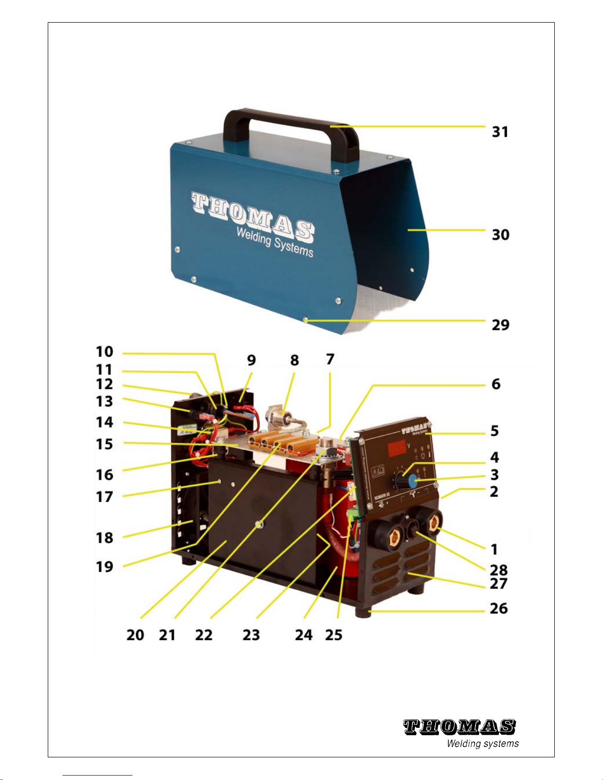
5.6 Explosion view of NOMARK 65 / 99
56
Fig. 5 - 18 Explosion view NOMARK 65 / 99.
Page 58

Item Article no. Part /description Qty
1. 650.668 Panel mounting weld socket 2
2. 101.002 Panel plug link “U” bar 1
3. 101.003 Knob cap 1
4. 101.004 Knob 1
5. 101.005 Control Panel overlay (NOMARK 65) 1
or 101.040 Control Panel overlay (NOMARK 99) 1
6. 101.006 Negative bus bar 1
7. 101.007 Mounting Pillar 2
8. 101.008 Free wheel diode 1
9. 101.009 Mains On/Off switch 1
10. 101.010 Earth screw 1
11. 101.011 Strain Relief 1
12. 101.012 Cord set (230V) 1
13. 101.013 Fuse holder 1
122.987 T 6.3 A Fuse (Not shown) NOMARK 65 / 230 V 1
or 100.014 T 10 A Fuse (Not shown) NOMARK 65 / 115 V 1
or 100.014 T 10 A Fuse (Not shown) NOMARK 99 / 230 V 1
14. 101.014 Main filter 1
15. 101.015 Positive bus bar 1
16. 101.016 Insulator Nut 4
17. 101.017 Thermal switch for fan control (NOMARK 65) 1
or - No Thermal switch (NOMARK 99) 0
18. 101.018 Fan 1
19. 101.019 Resistor (NOMARK 65) 4
or 101.019 Resistor (NOMARK 99) 5
20. 101.020 Mounting plate 1
or 101.061 Mounting plate NOMARK 65 / 115 V 1
101.062 Terminal Block NOMARK 65 / 115 V 1
21. 101.021 Welding SCR (NOMARK 65) 1
or 101.050 Welding SCR (NOMARK 99) 1
101.051 SCR Box clamp (NOMARK 99) 1
101.052 SCR Mounting plate (NOMARK 99) 2
101.053 Positive connection cable 1
22. 101.022 Control & Display PCB (NOMARK 65)
Fuse F2 : T 6.3 A
1
or 101.022 Control & Display PCB (NOMARK 99)
Fuse F2 : T 10 A
1
23. 101.023 Main transformer (NOMARK 65) 1
or 101.060 Main transformer (NOMARK 65 / 115V) 1
or 101.054 Main transformer (NOMARK 99) 1
24. 101.024 33.000 µF capacitors (NOMARK 65) 2
or 101.024 33.000 µF capacitors (NOMARK 99) 3
25. 101.025 PCB Connector 1
26. 101.026 Casing foot 4
27. 101.027 Housing base plate 1
28. 101.028 Panel mounting control socket 1
29. 101.029 Housing cover screw 12
30. 101.030 Housing cover 1
31. 101.031 Carrying handle 1
57
Tab: 5 - 19 Replacement parts list NOMARK 65 / 99
Page 59
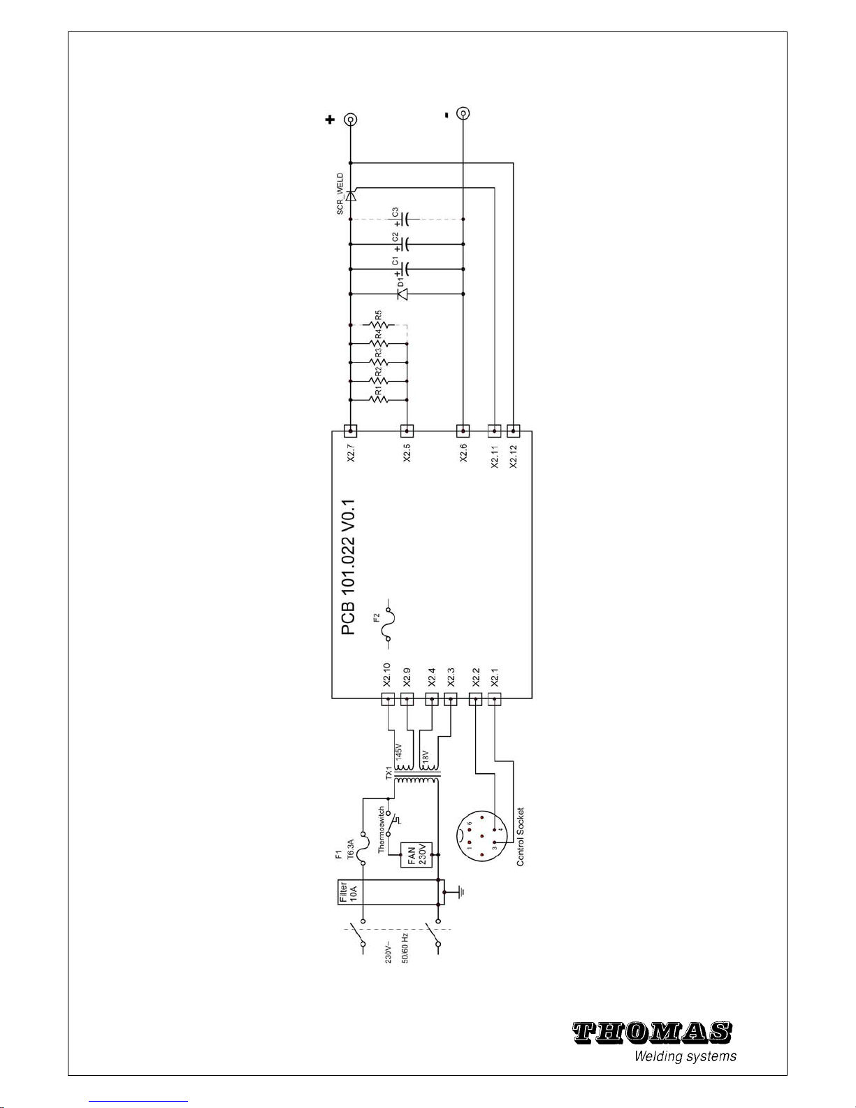
5.7 Block circuit diagram
58
Fig. 5 - 20 Block circuit diagram
Page 60

5.8 Technical specifications
C0 Gun
Type contact stud welding gun C0
Welding range M3 – M8 (M 10)
Weight 0,6 kg (without cable)
Noise level max. 107 dB(A)
Welding & control cable length: 4 m
Weld cable cross section: 25 mm2
Fig. 5 - 21 Dimensions C0
Fig. 5 – 22 Control cable plug connection
For procurement of replacement parts for the power unit and gun, see the exploded views.
Warning: Repair work on the power unit may only be carried
out by electricians.
It is expressly pointed out that the parts may only be stripped to
the degree of dismantling shown in the exploded views!
59
Page 61

5.9 Explosion view of C0 Gun and ground clamps
60
Spare parts for C0 gun
Part Number
1.
102.150 C0 Gun complete with cable
102.151 C0 Gun complete without cable
2.
102.152 Spring (Cable protection)
3.
102.153 Cable (4 meters), with connectors
4.
110.020 Weld male plug
5.
110.304 4 poles connector, cable end
6+7+8
102.154 Key set
9.
Chuck (see welding accessories)
102.165 Complete double ground with cable
102.160 Ground Clamp
(Sold individually. If you need a pair,
be sure to order two)
Page 62
61
Spare parts for C0 gun
Page 63
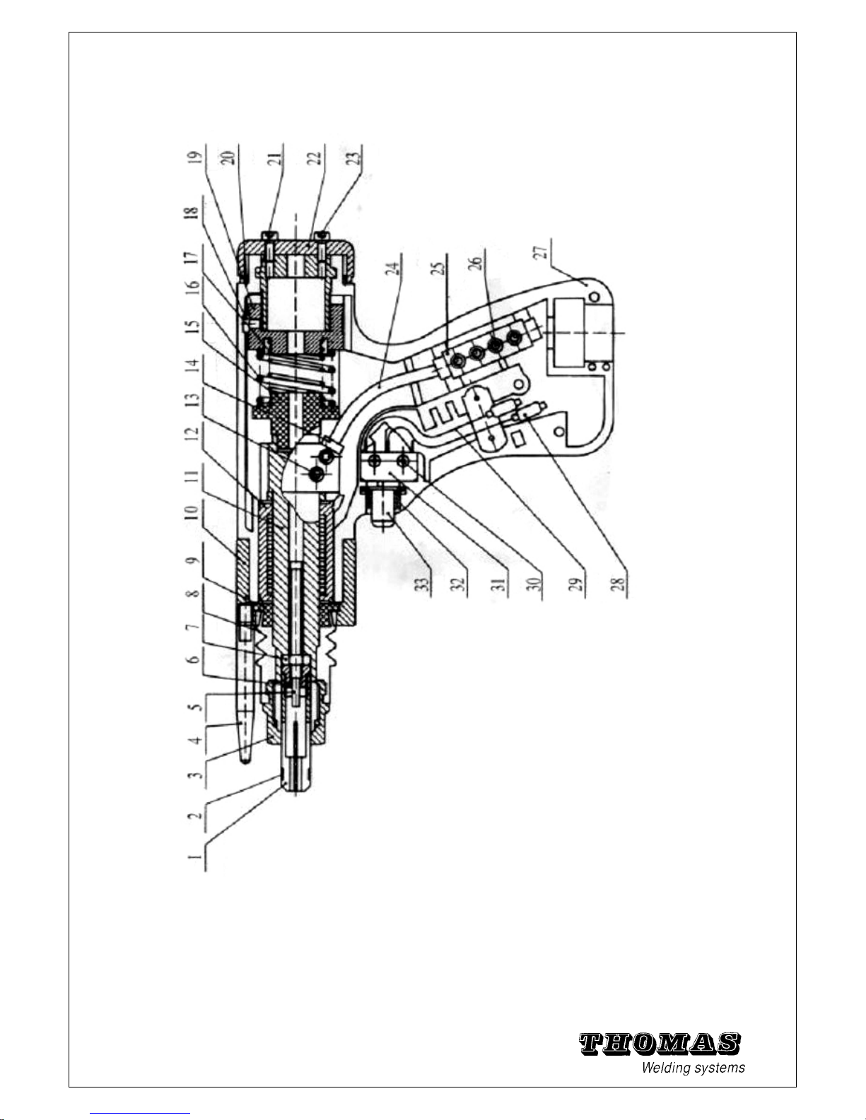
Spare parts for C0 gun
Item Part number
Description
Quantity
1.
Depends on chuck Ø
Chuck
-
2.
190.053
“O” ring
-
3.
102.103
Chuck nut
1
4.
190.002
Tripod Leg. (Ø 6 x 50 mm)
Can be replaced by C1/G1 legs
3
5+6+7
190.042
backstop locking nut
-
8.
102.108
Dust protection Bellow
1
9.
102.109
bellow retaining ring
1
10.
102.110
Front end cap / Legs holder
(Supplied without leg)
1
11.
102.111
Spindle
1
12.
102.112
Bearing bush
1
13.
102.113
Screw
2
14.
102.114
Ferrule
1
15.
102.115
Fixed spring seat
1
16.
102.116
Spring
1
17.
102.117
Spring
1
18.
102.118
Supplied with part nr 19
1
19.
102.119
Adjustable spring seat
1
20.
102.120
Back cap ring
1
21.
102.121
Spring preload adjuster
1
22.
102.122
Back cap
1
23.
102.123
Back cap screw
2
24.
102.124
Flexible braid assembly
1
25.
102.115
Cable splicing block
1
26.
102.126
Screw
4
27.
102.127
Gun body moulding (2 parts)
1
28.
102.128
Sleeve
2
29.
102.129
Trigger wires
1
30.
102.130
Screw (trigger switch)
2
31.
102.131
Trigger micro switch
1
32.
102.132
Trigger bezel (supplied with nr 33)
1
33.
102.133
Trigger push button
1
,
62
Fig. 5 - 23 Explosion view standard contact pistol C0
Page 64

63
5.10 Welding accessories
CD Accessories for C0
1. CHUCK
190.104 Chuck CD Ø 3 mm
190.108 Chuck CD Ø 4 mm
190.112 Chuck CD Ø 5 mm
190.116 Chuck CD Ø 6 mm
190.120 Chuck CD Ø 7,1 mm
190.124 Chuck CD Ø 8 mm
190.128 Chuck CD Ø 10 mm
(Depending on the stud length,
Additional parts could be requested)
190.101 Chuck CD Ø 2.5 mm
2. CHUCK for Insulation pins
190.102 Chuck CFN Ø 2 mm
190.103 Chuck CFN Ø 3 mm
190.134 Chuck BIMETAL Ø 3 mm
( Ø int. = 6 mm x 13 mm)
3. CHUCK for Earth Tag CDL / CDLD
190.581 Chuck CDL 6,3 x 0,8 mm
Leg for tripod
190.002 Leg (Ø 6 x 50 mm)
Set of 3 is requested for the
standard tripod
Page 65

Offset chuck attachment
190.012 Offset chuck attachment
The Angled Extension Arm
allows the welding of studs
into corners and against
upstands.
190.205 CD tester bending bar
190.210 Bending bar nozzle Ø 3 mm
190.216 Bending bar nozzle Ø 4 mm
190.222 Bending bar nozzle Ø 5 mm
190.228 Bending bar nozzle Ø 6 mm
190.234 Bending bar nozzle Ø 8 mm
64
Page 66

5.11 Technical specifications
C1 Gun
Type contact stud welding gun C1
Welding range M3 – M8 (M 10)
Weight 0,6 kg (without cable)
Noise level max. 107 dB(A)
Welding cable length: 5 m
line cross section: 25 mm2
Control cable length: 5 m
Fig. 5 – 24 Dimensions C1
Fig. 5 – 25 Control cable plug connection
For procurement of replacement parts for the power unit and gun, see the exploded views.
Warning: Repair work on the power unit may only be carried
out by electricians.
It is expressly pointed out that the parts may only be stripped to
the degree of dismantling shown in the exploded views!
65
Page 67

5.12 Explosion view of C1 Gun
66
Spare parts for C1 gun
Page 68

Spare parts for C1 gun
Item Part number Description
Quantity
1.
102.301
Chuck Nut 1
2.
102.302
Bellow 1
3.
102.303
Bellow retainer 1
4.
102.304
Bearing bush 1
6.
102.306
Spindle 1
7.
102.307
Screw 1
8.
102.308
Fixed spring seat 1
9.
102.309
Main spring 1
11.
102.311
Screw 1
12.
102.312
Adjustable spring seat 1
13.
102.313
Shaft Key 1
16.
102.316
Rear back cap 1
21.
190.002
Tripod Leg 3
22.
102.322
Front end cap / Legs holder
(Supplied without leg)
1
23.
102.323
Back cap & front end cap Screws 3+2
24.
102.324
Gun body moulding (2 parts) 1
31.
102.331
Screw 3
32.
102.332
Trigger button 1
33.
102.333
Trigger bezel 1
34.
102.334
Cable securing clip 1
36.
102.336
Screw 2
37.
102.337
Trigger switch 1
38.
102.338
Screw 2
39.
102.339 Flexible braid assembly
1
41.
102.341
Split washer 1
42.
102.342
Screw 1
60.
102.360
Ring 1
80.
102.380
Label “C1” 1
102.381
Label “THOMAS Welding Systems” 1
90.
102.390
Complete Cable assy’ ( 5 meters) 1
91.
102.391
Control cable sleeve 1
92.
102.392
Weld cable sleeve 1
93.
102.393
Cable splicing block 1
94.
102.394
Cable tie clip 10
96.
110.314
Cable end control plug 1
97.
110.020
Cable end weld plug 1
106.
110.232
Control cable (m) 5,3
107.
110.213
Weld cable (m) 5
67
Fig. 5 - 26 Explosion view contact pistol C1
Page 69

68
5.13 Welding accessories
CD Accessories for C1 / G1
1. CHUCK
190.104 Chuck CD Ø 3 mm
190.108 Chuck CD Ø 4 mm
190.112 Chuck CD Ø 5 mm
190.116 Chuck CD Ø 6 mm
190.120 Chuck CD Ø 7,1 mm
190.124 Chuck CD Ø 8 mm
190.128 Chuck CD Ø 10 mm
(Depending on the stud length,
Additional parts could be requested)
190.101 Chuck CD Ø 2.5 mm
190.156 Chuck CD Ø 1/4
2. CHUCK for Insulation pins
190.102 Chuck CFN Ø 2 mm
Chuck CFN Ø 2.6 mm
190.103 Chuck CFN Ø 3 mm
190.134 Chuck BIMETAL Ø 3 mm
(Ø int. = 6 mm x 13 mm)
3. CHUCK for Earth Tag CDL / CDLD
190.581 Chuck CDL 6,3 x 0,8 mm
Page 70

69
Tool Ø 30 mm for template
190.008
Support Tube 30mm diameter.
The support tube allows stud
welding with templates and
positioning on curved surfaces
190.009 Longer version (+ 11 mm)
=> total length : 90 mm
Tool for reducing noise ( Ø 35 mm)
190.006 Reducing noise/spatter tool
Standard tripod leg assembly
190.014
Complete kit consisting of :
1. 190.002
Tripod leg (Ø 6 x 50 mm)
2. 102.323
M5 x 4
3.
102.322
Front end cap / Legs holder
(Supplied without leg,
but with 3 screws M5 x 4)
Leg for tripod
190.002 Leg (Ø 6 x 50 mm)
Set of 3 is requested for the standard tripod
190.003 Leg (Ø 6 x 116 mm)
Set of 3 is requested for the standard tripod
Other lengths : on request
Extension kit (for studs L > 40 mm)
190.016 Extension kit
(h = 16 mm)
Page 71

Socket spanner
190.295 Socket spanner SW 17
Tube for Template Ø 20, 26 et 30 mm
(allow welding of studs through templates with different diameter holes.)
190.30x
Complete Assembly:
190.310 1. Face plate
190.315 2. Spacer ( x 3 )
190.320 3. Screw-in ring
190.325 4. Centring rod
190.33x 8. Nose cone
190.34x 9. Centring cup
190.045 Longer Chuck Screw
x = 1 for Ø 20 mm.
x = 5 for Ø 26 mm.
x = 7 for Ø 30 mm.
Longer Chuck Back stop Screw
190.045 Chuck Back stop
Offset chuck attachment
190.012 Offset chuck attachment
The Angled Extension Arm
allows the welding of studs
into corners and against
upstands.
CD tester bending bar
Bending bar nozzle Ø 3 mm
Bending bar nozzle Ø 4 mm
Bending bar nozzle Ø 5 mm
Bending bar nozzle Ø 6 mm
Bending bar nozzle Ø 8 mm
70
Page 72

ISO Kit Accessories for C1 / G1
(for welding longs CD pins > 100 mm)
1. CHUCK
190.104 Chuck CD Ø 3 mm
190.108 Chuck CD Ø 4 mm
190.101 Chuck CD Ø 2.5 mm
2. Gun face plate
104.127 Face Plate
3. Foot plate + Nozzle
1. Leg (*)
190.201 8 x 170 mm
190.202 8 x 220 mm
190.203 8 x 300 mm
190.204 8 x 400 mm
190.205 8 x 500 mm
2. Foot washer
190.210
3. Foot screw
M 5 x 25 (or 30 mm)
190.215
4. Foot plate for Ø 35 mm nozzle 190.240
5 Ø35mm Nozzle 190.241
6. Teflon ring 190.242
(*) Leg length >= CD pins length. Sold individually. If you need a pair, be sure to order two
71
Page 73

72
ISO Kit Weld Gun specific setup
1. Adjust Chuck back stop screw.
There is a depth stop inside of the chuck (Chuck back stop screw)
The depth stop should be adjusted so that you are retaining a good portion of the stud you are
setting up to weld. Typically, this is 10 – 15 mm of the pins you are welding.
2. Seat weld pin firmly against chuck back stop Screw.
3. Loosen the legs adjustment screws.
4. To adjust the protrusion (plunge), loosen the leg set screws in the gun body. Move the foot
towards the gun or away from the gun to increase or decrease plunge. The plunge
measurements are from the end of the stud and do not include the welding tip.
Slide the Leg / Foot assembly until weld pin flange extends 2 to 5 mm beyond foot nozzle (spark
shield).
5. Retighten adjustment screw.
Page 74

73
5.11 Blank page for notes
Page 75

74
(No part of this document may be duplicated, passed on or communicated
to others or used otherwise unless expressly permitted.
Violations will be prosecuted to the full extent of the law. All rights reserved,
especially in the event of a patent being granted or a utility patent
being registered.)
(We have checked the contents of this publication for correspondence
with the hardware it describes. Nevertheless discrepancies cannot be
ruled out, for which reason we cannot guarantee complete correspondence.
However, the contents of this publication are checked regularly
and any corrections needed incorporated in following editions.
Please send us your recommendations for improvement.
TWS - THOMAS WELDING SYSTEMS ·
© 2013 All rights reserved · Subject to technical change
Address for orders:
THOMAS WELDING SYSTEMS SA
ZI - 3EME RUE
B-6040 JUMET
BELGIUM
www.thomas-welding.com
 Loading...