

Page 1

135TA/137/153
PUBLICATION NO. 52935
June 2005
Owner’s
and
Operator’s
Manual
Skid Steer Loader
Page 2

THOMAS EQUIPMENT LIABILITY WARRANTY
THE WARRANTY IS THE ONLY OBLIGATION OF THOMAS OR A THOMAS
DEALER TO THE PURCHASER OR ANYONE ELSE CONCERNING A PRODUCT, IT’S
SERVICE, IT’S USE OR PERFORMANCE OR IT’S LOSS OF USE OR FAILURE TO
PERFORM. NEITHER
THOMAS NOR A THOMAS DEALER HAVE MADE AND
NEITHER
WILL MAKE ANY OTHER EXPRESSED OR IMPLIED REPRESENTATION,
WARRANTY OR AGREEMENT
CONCERNING
A PRODUCT, NEITHER THOMAS NOR
A THOMAS DEALER HAVE MADE OR WILL MAKE ANY REPRESENTATION,
W
ARRANTY OR AGREEMENT CONCERNING A PRODUCT’S MERCHANTABILITY
OR OTHER QUALITY, IT’S SUITABILITY FOR PURCHASER’S PURPOSE (EVEN IF A
PURCHASER HAS INFORMED THOMAS OR A THOMAS DEALER OF THAT
PURPOSE), IT’S DURABILITY, PERFORMANCE OR OTHER CONDITION.
EVEN IF THOMAS OR A THOMAS DEALER WAS ADVISED OF THE
POSSIBILITY OF SUCH LOSS, NEITHER THOMAS NOR A THOMAS DEALER WILL BE
LIABLE TO PURCHASER OR ANYONE ELSE FOR ANY INDIRECT, INCIDENTAL
CONSEQUENTIAL, PUNITIVE, ECONOMIC, COMMERCIAL, OR SPECIAL LOSS
WHICH IN ANY WAY ASSOCIATED WITH A PRODUCT. THIS INCLUDES ANY LOSS OF
USE OR NON-PERFORMANCE OF A PRODUCT, ANY REPLACEMENT RENTAL OR
ACQUISITION COST, ANY LOSS OF REVENUE OR PROFITS, ANY FAILURE TO
REALIZE EXPECTED SAVINGS, ANY INTEREST COSTS, ANY IMPAIRMENT OF
OTHER GOODS, ANY INCONVENIENCE OR ANY LIABILITY OF THE PURCHASER TO
ANY OTHER PERSON.
PURCHASER MAY NOT ATTEMPT TO ENLARGE ITS RIGHTS UNDER THE
WARRANTY BY MAKING CLAIM, FOR INDEMNITY, FOR BREACH OF CONTRACT,
FOR BREACH OF COLLATERAL WARRANTY, FOR A TORT (INCLUDING
NEGLIGENCE, MISREPRESENTATION OR STRICT LIABILITY) OR BY CLAIMING
ANY OTHER CAUSE OF ACTION.
THE WARRANTY IS A CONDITION OF SALE OF THE PRODUCT TO THE
PURCHASER AND WILL THEREFORE APPLY EVEN IF THE PURCHASER ALLEGES
THAT THERE IS A TOTAL FAILURE OF THE PRODUCT.
N.B. Read and practice your Thomas operating and servicing instructions. Failure to do this may
void the warranty.
PUBLICATION NUMBER 52473
© Thomas Equipment Inc. 2005
Printed in Canada
Page 3

INDEX
1. SAFETY PRECAUTIONS
2. CONTROLS
2. 1 Instrument Panel
2. 2 Seat and Seat Belt
2. 3 Seat Bar
2. 4 Parking Brake
2. 5 Throttle Controls
2. 6 Lift Arm Supports
2. 7 Steering Controls
2. 8 Foot Pedals
2. 9 Quick - Tach
2. 10 Electrical Panel
3. OPERATION
3. 1 Starting Instructions
3. 2 Operating Procedure
3. 3 Filling From a Pile
3. 4 Digging with a Bucket
3. 5 Leveling and Backfilling
3. 6 Auxiliary Hydraulics
3. 7 Lifting
3. 8 Towing
3. 9 Securing and Transporting
3. 10 Lowering Lift Arms
4. MAINTENANCE
4. 1 Preventive Maintenance Service Schedule
4. 2 Service Access
4. 3 Daily Service Checks
4. 4 50 Hour Service Check
4. 5 150 Hour Service Check
4. 6 Final Drive Maintenance
4. 7 Hydraulic / Hydrostatic System Maintenance
4. 8 Engine Maintenance
4. 9 Air Cleaner Maintenance
4. 10 Engine Cooling System
4. 11 Electrical System
4. 12 Tire Maintenance
4. 13 Trouble Shooting
4. 14 Hydraulic / Hydrostatic Circuit
4. 15 Special Tools
5. SPECIFICATIONS
5. 1 Loader Specifications
5. 2 Torque Specifications
5. 3 Decals
6. ATTACHMENTS AND BUCKETS
6. 1 Thomas Approved Buckets and Attachments
Page 4
WARNING
This warning indicates
hazards or unsafe
practices which COULD
result in severe personal
injury or death.
This warning indicates an
immediate hazard which
WILL result in severe
personal injury or death.
DANGER
Instructions are necessary
before operating or
servicing this machine.
Read the operators manual
and service decals on the
loader. Follow warnings and
instructions in this manual
when making repairs,
adjustments or servicing.
Check for correct operation
after adjustments and
repairs.
IMPORTANT
This notice shows
important procedures
which must be followed
to prevent damage to the
loader or attachment.
IMPORTANT
This warning indicates
hazards or unsafe
practices which COULD
result in minor personal
injury or product or
property damage.
CAUTION
FOREWORD
This book has been written to give the Owner / Operator necessary operating,
servicing and preventative maintenance instructions on the loader.
Read this manual completely and know the loader before operating or servicing it.
Do not do any service procedures that are not in the Operator’s manual.
Only service personnel that have had training in the service of this loader can do these
service procedures.
Reference Information
Write the correct information for your loaders in the spaces below. Always use these
numbers when referring to your loader.
Model No.
Serial No.
Dealer Name
Address
Phone
Throughout this manual the terms DANGER, WARNING and CAUTION are used to
indicate the degree of hazard in terms of personal safety. These words will be used in
conjunction with the Safety - Alert symbol, a triangle with an exclamation mark.
Throughout this manual, the term IMPORTANT is used
* To indicate that instructions are necessary before operating or servicing the
loader.
* To show important procedures which must be followed to prevent damage to
the loader or attachment.
Page 5

5
1. SAFETY PRECAUTIONS
The following precautions are suggested to help prevent accidents.
A careful operator is the best operator. Most accidents can be avoided by observing certain precautions. Read and take the
following precautions before operating this loader to help prevent accidents. Equipment should be operated only by those
who are responsible and instructed to do so.
1. Read this manual carefully before using the loader.
Working with unfamiliar equipment can lead to accidents.
2. Do not allow anyone to ride on the loader with the
operator.
3. Make sure the seat bar is installed and functioning at all
times.
4. Never run the engine in a closed building without
adequate ventilation, as the exhaust fumes can cause
death.
5. Always fasten the seat belt around your waist before
starting the engine. Never fasten the seat belt behind you.
6. Never attempt to start the engine while standing beside
the unit unless as specified in this manual or under
specific service and backhoe operation procedures. Start
the engine only while sitting in the operator’s seat with
the seat belt fastened around you. Always check to make
certain that the seat cushion is secured to the frame.
7 Keep the operator’s area free of debris.
8. Never enter or leave the loader while the engine is
running. Always lower the lift arms down against the
frame, drop the attachment down to contact the ground,
set the parking brake and shut off the engine prior to
leaving the loader.
9. If the unit is equipped with a cab enclosure kit always
close the door prior to operating the loader lift arms.
10. Do not operate the loader unless all safety equipment,
shields, seat belt, seat bar, hydraulic controls, parking
brake, operator guard, and lift arm supports are working
properly, as well as all safety and instruction decals are in
place.
OPERATING THE LOADER
1. Always drive the loader at speeds compatible with safety,
especially when operating over rough ground, crossing
ditches or when turning.
2. Avoid jerky turns, starts, stops, or reverses.
3. Use care when operating on steep grades to maintain
proper stability.
4. Do not turn the loader while the lift arms are in the
raised position.
5. Be careful when driving through door openings or under
overhead objects. Always make sure there is sufficient
clearance for the operator’s guard.
6. When travelling on public roads, know the local rules and
regulations and make sure your loader is equipped with
the proper safety equipment.
7. Always be sure of water, gas, sewage and electrical line
locations before you start to dig.
8. Watch out for overhead and underground high-voltage
electrical lines when operating the loader.
9. Always park the loader on level ground where possible. If
the loader is to be parked on an incline, always lower the
attachment so it contacts the ground, set the parking brake
and block the wheels.
10. Do not leave the loader when it is in motion.
11. Do not dismount from the loader and leave the loader lift
arms raised, unless following specific service procedures.
Always lower the lift arms down against the frame and
drop the attachment down to contact the ground.
12. Always be watchful of bystanders when operating the
loader.
13. Always carry the attachment low for maximum stability
and visibility.
14. Exercise extreme caution when operating the loader with
a raised attachment.
15. Never attempt to lift loads in excess of loader capacity.
16. Check that the foot pedals are locked before getting out of
the operator’s seat.
17. Keep both hands on the control levers while the loader is
in motion.
MAINTENANCE
1. Stop the engine before performing any service on the
loader.
2. Never refuel the loader while smoking or with the engine
hot or running.
3. Replace all missing, illegible or damaged safety and
warning decals. See Section 5.3 for list.
4. Do not modify or alter, or permit anyone to modify or
alter this loader or any of its components or any loader
function.
5. Do not bypass the safety system. Consult your Thomas
Equipment Dealer if your safety controls are
malfunctioning.
6. Do not make mechanical adjustments while the loader is
in motion or when the engine is running. However, if
minor engine adjustments must be made, securely block
the loader with the wheels clear of the ground, and use
extreme caution.
7. Do not attempt to repair or tighten hydraulic hoses when
the system is under pressure, when the engine is running
or when the lift arms are raised.
8. Do not get under the attachment or lift arms or reach
through the lift arms when they are raised.
9. Never attach the chains or ropes to the operator’s guard
for pulling purposes, as the loader can tip over.
10. Whenever servicing or replacing pins in cylinder ends,
buckets,
etc., always use a brass drift and a hammer.
Failure to do so could result in injury from flying metal
fragments.
11. Cooling system operates under pressure which is
controlled by the radiator cap. It is dangerous to remove
the cap while system is hot. Always turn cap slowly to the
first stop and allow the pressure to escape before
removing the cap entirely.
12. Keep the operator and foot pedal areas free from debris.
13. For lifting and towing instructions, refer to Sections 3.7
and 3.8 of this manual.
Page 6
To prevent personal
injury do not start the
engine unless you are in
the seat with the seat belt
fastened around you.
WARNING
To prevent personal
injury do not operate the
loader without lowering
the safety bar, fastening
the seat belt and keeping
feet on the control pedals
or cab floor.
WARNING
This engine is equipped
with glow plugs. Do not
use ether or any high
energy fuels to assist
starting.
IMPORTANT
C-359
6
1. SAFETY PRECAUTIONS
To avoid personal injury,
lower the lift arms, shut off
the engine, raise the seat bar
and cycle the hydraulics to
ensure they are locked.
Then, unlatch the seat belt
and exit the loader. Do not
enter or exit with the engine
running unless as specified
in this manual or under
specific service and backhoe
operating procedures.
WARNING
START SAFELY
1. Sit in the operator’s seat and adjust it so you can operate
all of the controls properly.
2. Adjust the seat and fasten the seat belt. Cycle the
controls to make sure they are in the locked or neutral
position. Lower the seat bar.
3. Know the exact starting procedure for your machine.
See Section 3 for the manufacturer’s instructions for
starting.
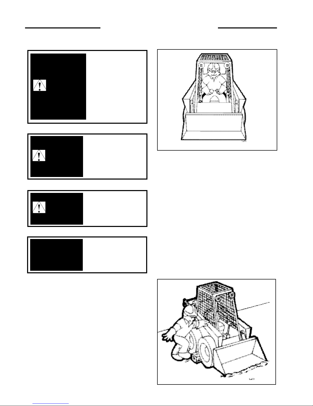
PARK SAFELY
Select level ground whenever possible. If you must park
on a slope or incline, position the machine at right angles
to the slope. Lower the attachment to the ground, engage
the parking brake and block the wheels (C359).
C - 360
Page 7

7
2. CONTROLS
2. 1 Instrument Panel
2. 2 Control Lever Handles
2. 3 Seat and Seat Belt
2. 4 Seat Bar
2. 5 Parking Brake
2. 6 Throttle Control
2. 7 Lift Arm Supports
2. 8 Steering Controls
2. 9 Auxiliary Controls
2. 10 Foot Pedals
2. 11 Hand Controls
2. 12 Quick-Tach
2. 13 Electrical Panel
2. CONTROLS
Page 8
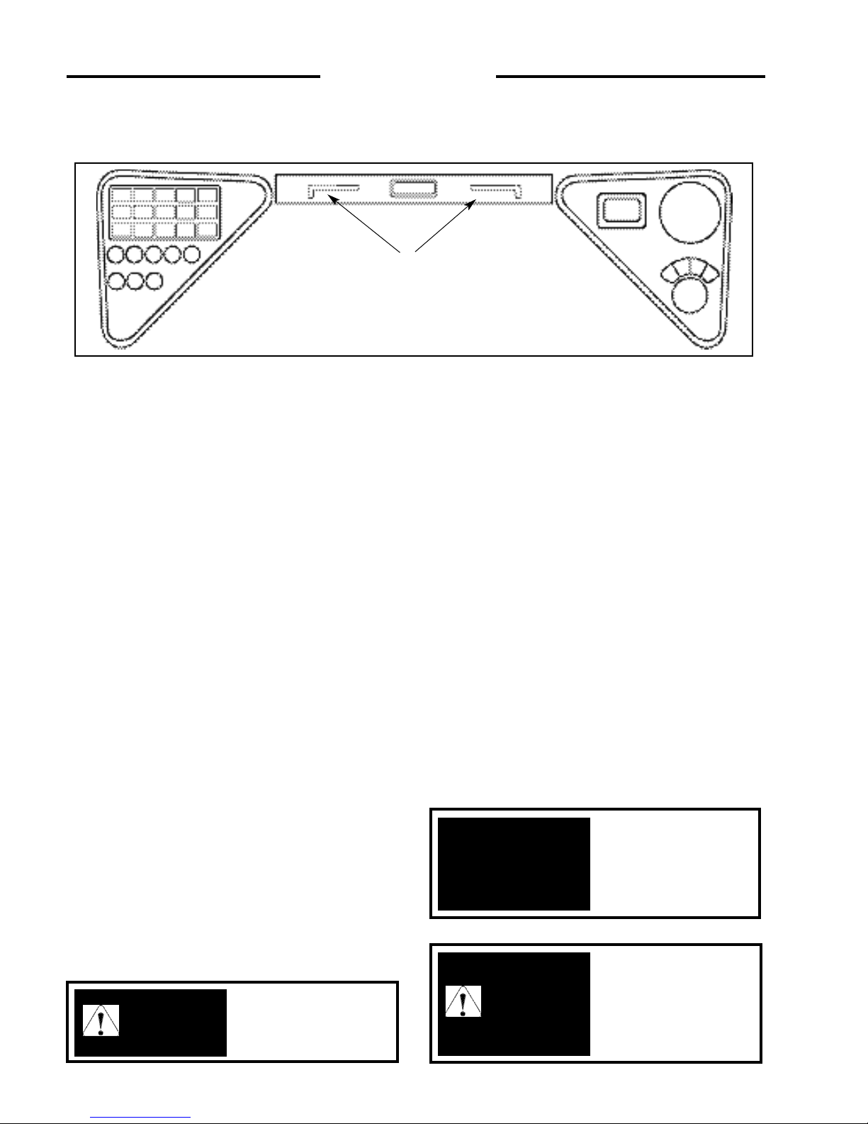
1. Fuel Gauge: The fuel gauge indicates the quantity of
fuel remaining in the fuel tank.
2. Ignition Switch: The ignition switch is a four (4)
position switch: ‘OFF’, ‘PRE-HEAT’, ‘RUN’ and
‘START’. Turn the key counter clockwise to engage
engine ‘PRE-HEAT’. Turn the key clockwise to the
‘START’ position, this engages the starter. The key will be
in the ‘RUN’ position when released. Turn the key to
‘OFF’ to shut off the engine and remove the key.
3. Hour Meter: The hour meter records the number of
engine operating hours and has a total of 9999.9 hours.
4. Left Signal Indicator Light: This light will illuminate
when the operator uses the optional left signal (not
available on all models).
5. Auxiliary Front Indicator Light: This light will
illuminate when the loader auxiliary hydraulic front switch
(not available on all models) is turned on.
6. Hi-Flow Hydraulics Indicator: This light will
illuminate when the loader hi-flow hydraulics (not
available on all models) are in use.
7. Work Lights Indicator: This light will illuminate
when the loader work lights are turned on. This will serve
as a reminder to turn them OFF when the loader is not in
use.
8. Right Signal Indicator Light: This light will
illuminate when the operator uses the optional right signal
(not available on all models).
9. Hydraulic Oil Temperature Indicator: This light will
illuminate when the oil temperature has exceeded
recommended levels. Shut off the engine immediately and
determine the cause.
10. Brake Indicator Light: The brake light will
illuminate when the parking brake is engaged.
11. Seat Belt Indicator Light: This light will illuminate
when the seat belt is unfastened.
12. Hydraulic Oil Pressure Indicator Light: This light
will illuminate when there is low hydraulic oil pressure. If
this light illuminates, shut off the engine and determine the
cause (not available on all models).
13. Rotary Beacon Indicator: This light will illuminate
when the optional rotary beacon (not available on all
models) is turned on.
14. Engine Oil Pressure Indicator: This light will
illuminate when the engine loses lubrication pressure. Shut
off the engine immediately and determine the cause.
15. Coolant Temperature Indicator Light: This light
will illuminate if there is a rise in engine temperature. If
this occurs, shut off the engine immediately and determine
the cause.
16. Alternator Indicator Light: This light will
illuminate when the alternator is not producing sufficient
current.
8
2. CONTROLS
2.1 INSTRUMENT PANEL
C3170
Fig. 2.1
To prevent personal
injury never add fuel to
the loader when the
engine is running or is
hot. NO SMOKING!
WARNING
4
To prevent personal
injury do not start the
engine unless you are in
the seat with the seat belt
fastened around you.
WARNING
This engine is equipped
with glow plugs. Do not
use ether or any high
energy fuels to assist
starting.
IMPORTANT
5
6
7
8
9
10
11
12
13
14
15
16
17
18
19
24
1
2
3
20
21
22 23
25
Page 9
9
17. Air Cleaner Indicator Light: This light will
illuminate when there is an obstruction in the intake or
when the air filter needs servicing. If this light illuminates,
stop the engine and service the cleaner (see section 4.9).
18. Pre-heat Indicator Light: This light will illuminate
when the ignition key is turned counter clockwise to
activate the engine glow plugs.
19. Dipped Beam Light Switch: This switch is a toggle
switch. Push up to turn the dipped beam lights on. These
lights are located on the front of the loader (not available
on all models).
20. Rotary Beacon Light Switch: This switch is a toggle
switch. Push up to turn the optional rotary beacon light on
(not available on all models).
21. Hazard Light Switch: This switch is a toggle switch.
Push up to turn the optional hazard light on (not available
on all models).
22. Work Light Switch: This switch is a toggle switch.
Push up to turn the optional work light on (not available
on all models). The light is located on the back of the
loader.
23. Auxiliary Hydraulics Front Switch: This switch is
a toggle switch. Push up to provide a continuous flow
of
hydraulic oil to the quick couplers when using an
attachment (not available on all models).
24. Lift Arm Supports: For safety while performing
service or maintenance, the loader is equipped with a lift
arm support device. Refer to section 2.6 for details.
25. Hi-Flow Hydraulic Switch: This switch is a toggle
switch. Push up to turn the hi-flow hydraulics on (not
available on all models).
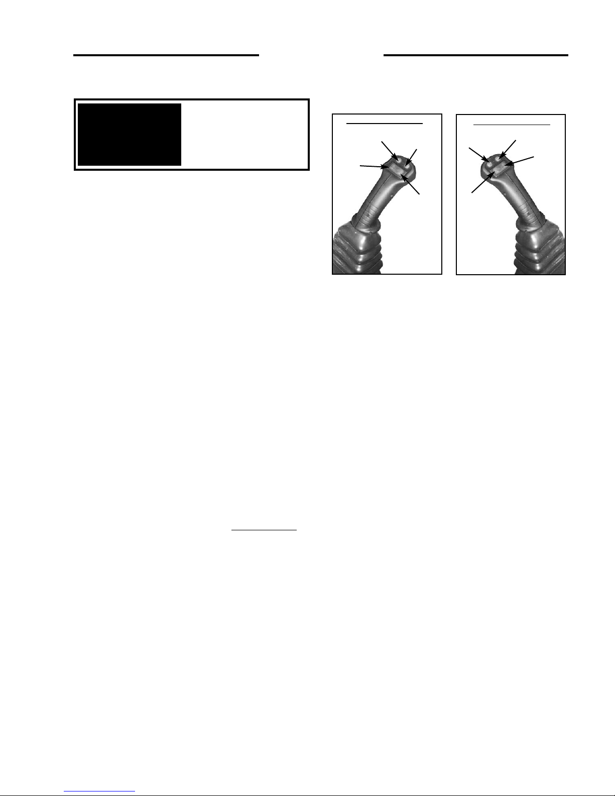
2.2 CONTROL LEVER HANDLES
1. Two Speed Switch (not available on all models):
This switch provides alternate switching. Press to activate
Hi-Speed function. Pressing and releasing the switch a
second time will return the loader to the Low-Speed
function. (Fig. 2.2A)
2. Horn Switch (not available on all models): This
switch is a momentary switch. Pressing and holding the
switch will activate the horn. Releasing the switch
deactivates the horn. (Fig. 2.2A)
3 & 4. Electric Solenoid Auxilliary Switch: This
switch is a momentary switch. Pressing and holding the
switch in position 3 provides hydraulic flow to the female
quick coupling. Pressing and holding the switch in position
4 provides hydraulic flow to the male quick coupling.
Releasing the switch returns it to neutral, stopping the
hydraulic flow. (Fig. 2.2A)
5. LH Directional Signal Switch (not available on
all models): This switch is a momentary switch. Pressing
and holding this switch will activate the LH turn signal.
Releasing the switch deactivates the LH turn signal. (Fig.
2.2B)
6. RH Directional Signal Switch (not available on
all models): This switch is a momentary switch. Pressing
and holding the switch will activate the RH turn signal.
(Fig. 2.2B)
7 & 8. Hi-Flow Hydraulic Switch (not available on all
models): This switch is a momentary switch. Pressing and
holding the switch in position 7 activates the hi-flow
hydraulics to the male quick coupling. Pressing and
holding the switch in position 8 activates the hi-flow
hydraulics to the female quick coupling. Releasing the
switch returns it to neutral and stops the hi-flowhydraulic
flow. (Fig. 2.2B)
Fully retract lift arm
support pins before
raising or lowering lift
arms.
IMPORTANT
2. CONTROLS
LH Control Handle
RH Control Handle
1
3
2
4
5
6
8
7
C3015
Fig. 2.2A
C3933
Fig. 2.2B
Page 10
2. CONTROLS
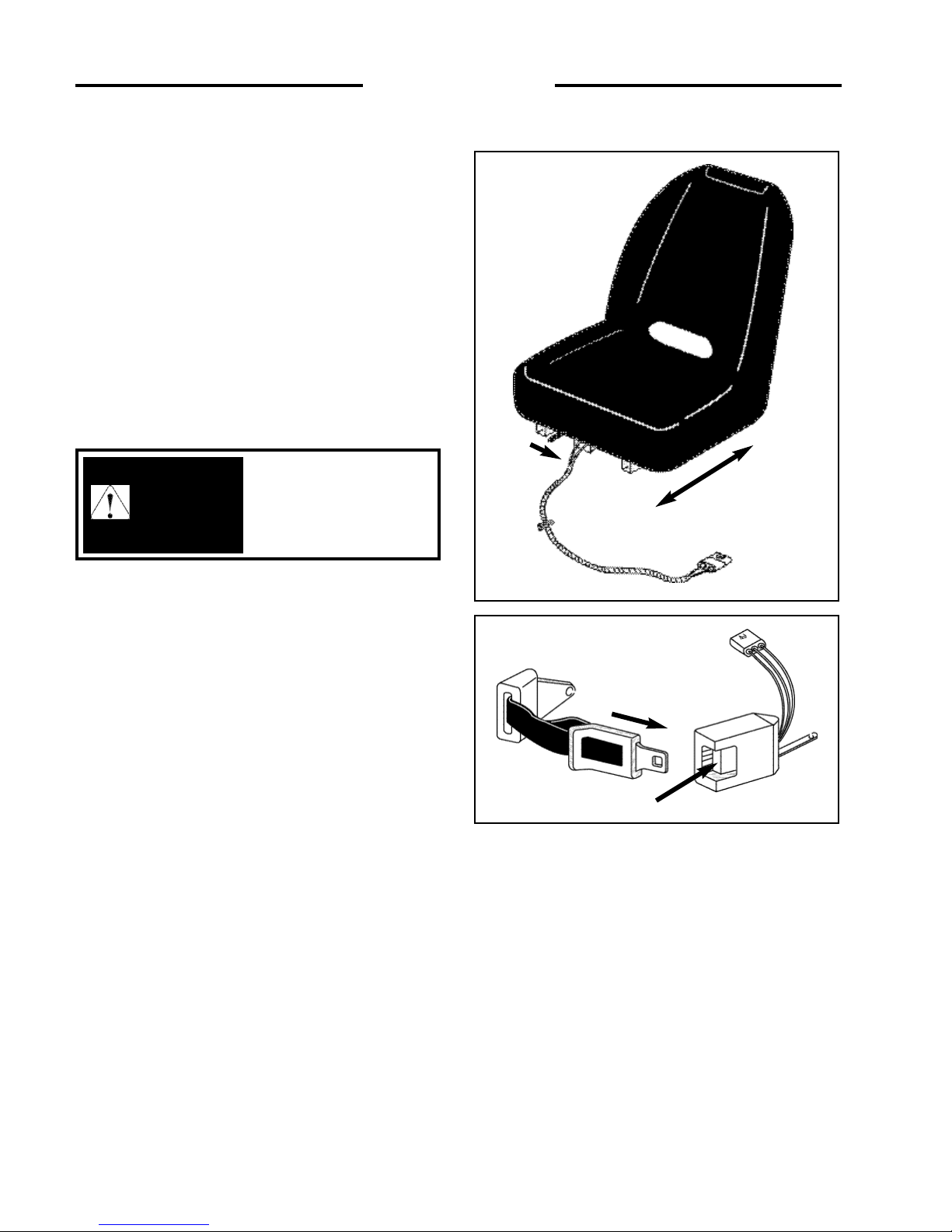
2.3 SEAT AND SEAT BELT
The loader is equipped with a deluxe seat. The seat can be
adjusted forward or back for operator comfort. (Fig. 2.2A).
For your safety the loader is equipped with a seat belt.
Before starting the loader adjust and fasten the seat belt
(Fig. 2.2B) around you. The seat and seat belt also have
integrated safety lock switches whereby the operator must
be seated in the seat with the seat belt securely fastened
and seat bar lowered before the loader hydraulics can be
operated.
To prevent personal
injury do not start the
engine unless you are in
the seat with the seat belt
fastened around you.
WARNING
Fig. 2.2B
C2698
Fig. 2. 2A
C2699
Release
10
Page 11
11
2. 4 SEAT BAR
For operator protection the loader is equipped with a seat
bar.
The loader must be started with the operator seated in the
loader and the seat bar in the up position. To raise the seat
bar, lift up on the bar (Fig. 2.3A). In the up position, the
seat bar activates the parking brake.
When down (Fig. 2.3B), the seat bar releases the park
brake and the hydraulic controls of the lift and tilt circuits.
Before exiting the loader always check the controls by
cycling them to ensure that they are in the neutral position.
2. CONTROLS
To avoid personal injury,
lower the lift arms, shut off
the engine, raise the seat bar
and cycle the hydraulics to
ensure they are locked. Then,
unlatch the seat belt and exit
the loader. Do not enter or
exit with the engine running
unless as specified in this
manual or under specific
service and backhoe
operating procedures.
WARNING
C3775
Fig. 2. 3A
C3776
Fig. 2. 3B
Seat Bar Up
Seat Bar Down
Page 12
12
2. 5 PARKING BRAKE
The loader is equipped with park brakes, located inside the
torque motor. The brakes are activated and de-activated
by the seat bar, via charge pressure. When the seat bar is
in the up position, the brake is activated (Fig. 2.4A). When
the seat bar is in the down position, the brake is off (Fig.
2.4B).
The loader has a parking brake indication light to warn that
the brake is engaged.
2. 6 THROTTLE CONTROL
The diesel engine throttle control is the lever located on
the left hand side of the loader next to the steering control
lever (Fig. 2.5). Engine start and stop are controlled
electrically by the ignition key.
Before shutting off the engine, return the throttle control to
idle position and allow the engine to cool at least 2
minutes.
Pushing the lever all the way forward increases the
engine speed to maximum high idle. Pulling the lever
back decreases the engine RPM.
The engine should always be operated at full speed and
the loader travel speed controlled with the steering
control levers (See Section 2.7).
2. 7 LIFT ARM SUPPORTS
For safety while performing regular service or
maintenance work the loader is equipped with lift arm
supports.
The lift arm supports, when extended, prevent the lift arms
from dropping if hydraulic pressure is relieved or the foot
control pedals are accidentally cycled.
To avoid personal injury,
lower the lift arms, shut off
the engine, raise the seat bar
and cycle the hydraulics to
ensure they are locked.
Then, unlatch the seat belt
and exit the loader. Do not
enter or exit with the engine
running unless as specified
in this manual or under
specific service and backhoe
operating procedures.
WARNING
C870
Fig. 2.5
2. CONTROLS
C3775
Fig. 2.4A
C3776
Fig. 2.4B
Seat bar UP
(Parking Brake On)
Seat bar DOWN
(Parking Brake Off)
Page 13
13
To operate the lift arm supports, first remove any bucket or
attachment from the quick - tach; raise the lift arms to full
height and shut OFF the engine. Push the two lift arm
support pin handles located directly in front of the operator
at the top of the operator compartment (Fig. 2.6A) outward
extending the lift arm locking pins (Fig. 2.6B). Slowly
lower the lift arms down onto the pins. To retract the
support pins, first lift the lift arms off of the pins before
retracting.
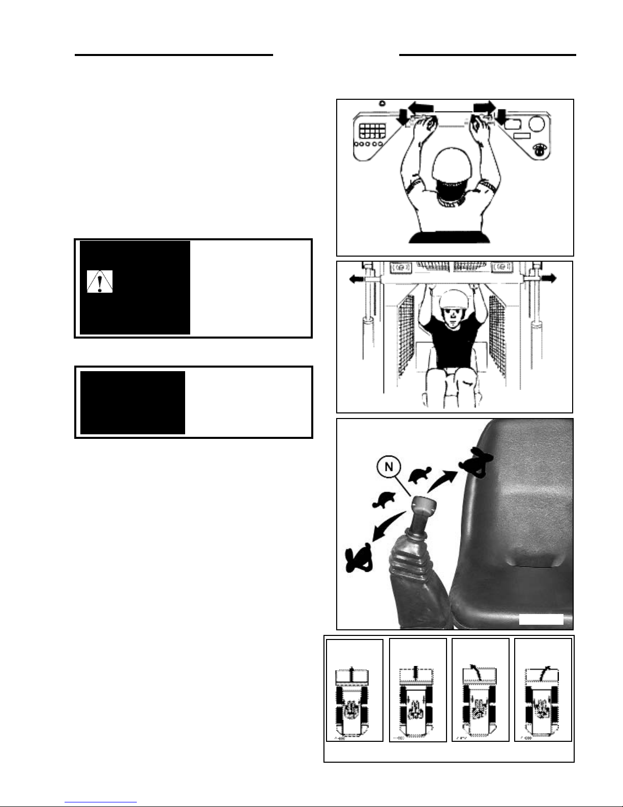
2. 8 STEERING CONTROLS
The two steering levers control speed, direction and
turning of the loader. The R.H. lever controls the wheels
on the R.H. side of the loader and the L.H. lever the L.H.
wheels. Loader speed is controlled by the amount each
lever is moved from centre or neutral position. (Fig. 2.7A)
The further away from neutral the faster the travel speed.
For maximum power and slow travel speed move the
control levers only a small amount.
To drive the loader forward in a straight line, move both
control levers forward the same amount (Fig. 2.7B).
To drive the loader in reverse in a straight line, move both
control levers back the same amount (Fig. 2.7B).
The loader is turned by moving one lever further forward
than the other. To turn right, move the left lever further
than the right lever. To turn left, move the right lever
further than the left lever (Fig. 2.7B).
For the loader to turn or “skid-steer” within its own length,
one lever is moved forward and the other back. This causes
the wheels on one side to turn forward and the wheels on
the other side to reverse turning the loader (Fig. 2.7B).
Fully retract the lift arm
supports before raising
or lowering lift arms.
IMPORTANT
2. CONTROLS
C - 694
Fig. 2. 6B
C3135
Fig. 2. 6A
C3938
Fig. 2.7A
C - 696 - 9
Fig. 2.7B
FORWARD REVERSE
LEFT TURN RIGHT TURN
To avoid personal injury do
not start the engine unless
you are in the seat with the
seat belt fastened around
you, unless as specified in
this manual or under
specific service and backhoe
operating procedures.
WARNING
Page 14

14
2. CONTROLS
C3793a
Fig. 2.8B
C3015
Fig. 2.8A
C4086
Fig. 2.8C
2.9 ELECTRIC SOLENOID
AUXILIARY CONTROLS
Auxiliary hydraulics (solenoid operated - standard)
A switch located on the L.H. steering control lever (Fig. 2.8A)
is used to engage the loader’s auxiliary hydraulic circuit to
power attachments such as post hole augers, sweepers, etc.
Pressing and holding the switch in position 1 (fig. 2.8A)
provides hydraulic flow to the female quick connect coupling
located at the front of the lift arms (fig. 2.9C). Releasing the
switch returns the auxiliary hydraulic circuit to neutral,
stopping the hydraulic flow.
Pressing and holding the switch in position 2 (fig. 2.8A)
provides hydraulic flow to the male quick connect coupling
located at the front of the lift arms (fig. 2.8C). releasing the
switch returns the auxiliary hydraulic circuit to neutral,
stopping hydraulic flow.
For continuous flow to the auxiliary hydraulic circuit, a toggle
switch is located on the L.H. instrument panel (fig. 2.8B).
Placing the switch in the “ON” position provides continuous
hydraulic flow to the female quick connect coupling located
at the front of the lift arms (fig. 2.8C). To stop hydraulic flow
to the auxiliary hydraulic circuit, return the switch to the
“OFF” position (fig. 2.8B). When the switch on the
instrument panel is in the “ON” position, the switch located in
the L.H. control lever is not operable.
NOTE: See Section 2.2 for information on the control
handles.
AUXILIARY HYDRAULIC CONTROL
1
2
NEUTRAL
ROPS SIDE
SEAT SIDE
TOGGLE
SWITCH
T avoid persinal injury,
lower the lift arms, shut off
the engine, raise the seat bar
and cycle the controls to
ensure they are locked.
Then, unlatch the seat belt
and exit the loader. Do not
enter or exit with the engine
running unless as specified
in this manual or under
specific service and backhoe
operating procedures.
WARNING
Male Quick Coupling
Female Quick Coupling
Page 15
15
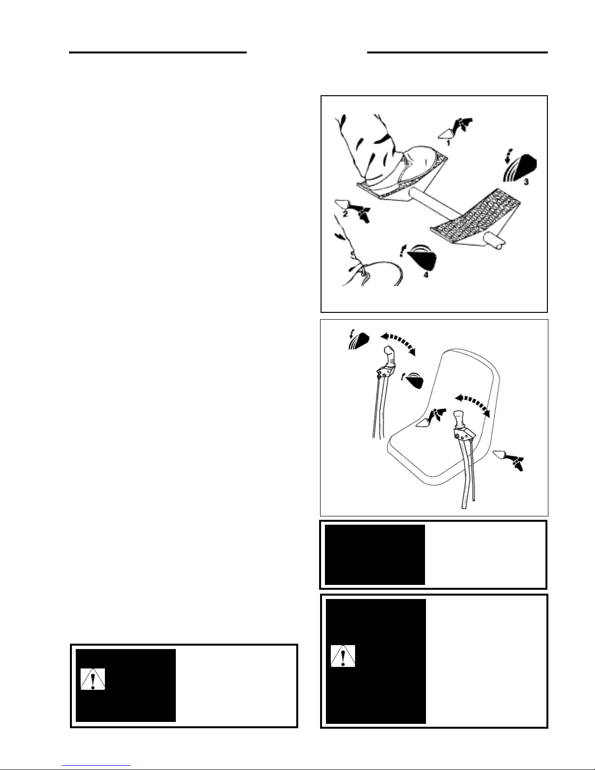
2.10 FOOT CONTROLS
Operation of the lift cylinders and the bucket tilt cylinders
are controlled by the foot pedals (fig. 2.10) connected to a
hydraulic control valve. The hydraulic control valve is a
series type valve which allows simultaneoous use of both
the lift and bucket tilt circuits.
Lift –
The L.H. pedal is the lift control (Fig. 2.10). To raise
the lift arms press on the heel (2) of the pedal. To lower the lift
arms press on the toe (1) of the pedal. Firm pressure on the toe
(1) of the pedal will lock the lift arms in float position. This
allows the bucket to follow the ground as the loader moves
backward.
Bucket Tilt –
The R.H. pedal is the bucket tilt (dump)
control. Pressing on the toe (3) of the pedal will dump the
bucket. Pressing on the heel (4) of the pedal will roll the bucket
back.
2. 11 HAND CONTROLS
Hand controls to operate the loader’s lift arm and bucket
hydraulic system as well as the loader’s travel speed and
direction are available. Refer to previous section for
instructions on steering controls.
LIFT ARM AND BUCKET CONTROLS
The right hand lever controls the bucket tilt cylinders
(2.11). Moving the control lever to the right causes the
bucket to dump. Moving the lever to the left rolls the
bucket to the carry position.
Moving the left hand control lever (Fig. 2.11) to the left
will cause the lift cylinders to extend, raising the loader’s
lift arms. Moving the control lever to the right causes the
lift cylinder to retract, lowering the lift arms. Moving the
control lever to the extreme right will place the lift arms in
the float position. This allows the bucket to follow the
contour of the ground as the loader moves backward.
When the control levers are released they will
automatically return to the neutral position, stopping all
hydraulic movement and travel speed. Before exiting the
loader, lower the lift arms completely down to the frame
and ground the attachment. Then shut off the engine. Move
both levers to the left and right to ensure the hydraulic
controls are locked before you get out of the loader.
2. CONTROLS
To prevent personal
injury do not operate the
loader without lowering
the safety bar, fastening
the seat belt and keeping
feet on the control pedals
or the cab floor.
WARNING
To avoid personal injury,
lower the lift arms, shut
off the engine, raise the
seat bar and cycle the
hydraulics to ensure they
are locked. Then unlatch
the seat belt and exit the
loader. Do not enter or
exit with the engine
running unless as
specified in this manual
or under specific service
and backhoe operating
procedures.
WARNING
C - 669
Fig. 2.10
Return the auxiliary
hydraulic control to the
neutral position when not
in use.
IMPORTANT
Fig. 2.10
C3020
Page 16
16
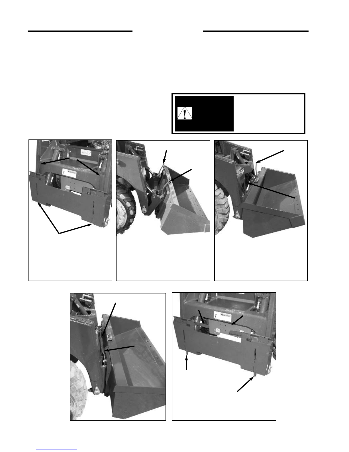
2.12 QUICK - TACH
The quick - tach, which is standard equipment, allows
changing from one attachment to another quickly without
having to remove bolt or pins.
To operate, (Fig. 2.11A), lift the locking lever (1) up to
completely retract the locking pins (2). Tilt the quick - tach
frame forward (Fig. 2.11B) with the bucket tilt cylinders and
drive into the attachment. Retract the bucket tilt cylinders
(Fig. 2.11C) which will line up the bottom of the attachment
with the quick - tach lock pins. Shut off the engine.
Push the locking lever (1) fully down (Fig. 2.11D) extending
the lock pins (Fig. 2.11E item 2) through the attachment and
securing the attachment.
Before operating the attachment check that the locking pins
are correctly engaged.
After hooking up the
attachment check to be
sure pins and locking
levers are correctly
engaged.
WARNING
C3967
C3964
Fig. 2.11B
Fig. 2.11A
C 3966
C 3968
Fig. 2.11E
1
1
2
Fig. 2.11D
1
2
1
C3965
Fig. 2.11C
1
1
1
1
2
1
2. CONTROLS
Page 17
17
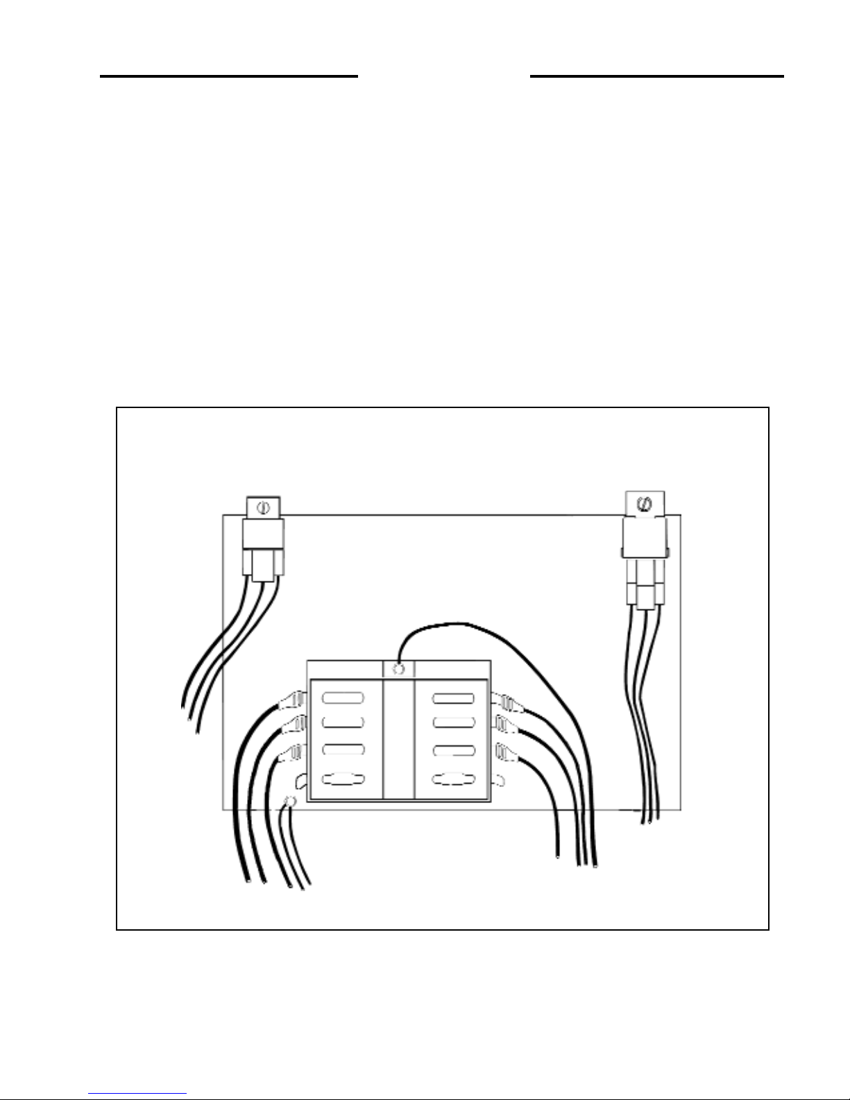
2.13 ELECTRICAL PANEL
The loader is equipped with a 12 volt, negative ground
electrical system. The fuse and relay panel are located in
the engine compartment on the engine cover. The panel
consists of the following:
1. Engine Pre-Heater Relay.
2. Starter Relay.
3. Fuse Panel.
FUSE PANEL (3)
4. Electric Fuel Solenoid Shutoff (15A)
5. Alternator Light (10A)
6. Electric Auxiliary (10A)
7. Spare
8. Spare
9. Valve Locks (10A)
10. Horn (Optional) (10A)
11. Spare
2. CONTROLS
Fig 2.12
C672
STARTER RELAY
PRE-HEATER RELAY
1
2
4
5
6
7
8
9
10
11
3
Page 18

18
3. OPERATION
3. 1 Starting Instructions
1. Pre-Starting Inspection
2. Starting Procedure
3. Shut-Off Procedure
3. 2 Operating Procedures
3. 3 Filling From a Pile
3. 4 Digging With a Bucket
3. 5 Leveling and Backfilling
3. 6 Auxiliary Hydraulics
3. 7 Lifting
3. 8 Towing
3. 9 Securing and Transporting
3. 10 Lowering Lift Arms
3.11 Accumulator
3. OPERATION
Page 19

19
3.1 STARTING INSTRUCTIONS
1. Pre-Starting Inspection
Before starting the loader complete the following
inspection:
(1) Check the hydraulic oil level, engine oil level, engine
coolant level and fuel supply.
(2) Check for fuel, oil and hydraulic leaks.
(3) Check lights, battery level and cables.
(4) Check tire pressure:
10.00 x 16.5 . . . . 40 - 45 PSI (276 - 310 kPa)
(5) Check wheel nut torque 100 - 110 ft. lbs. (136- 149
Nm).
(6) Lubricate all grease fittings.
(7) Check the condition and operation of all safety decals
and equipment – Ensure all shields and safety screens
are in place. If necessary repair or replace before
starting.
For complete daily servicing refer to section 4. 3.
2. Starting Procedure – Diesel
1. Ensure the seat bar is in the UP position and the
steering controls are centered and the foot pedals
locked.
2. Adjust and fasten the seat belt securely around you.
3. Place the throttle control in idle position.
4. Turn the ignition key counter clockwise to activate the
glow plugs. Hold approximately 15 seconds. Both the
alternator and engine oil pressure warning lights
should be on.
5. Turn the key clockwise to start position to engage the
starter. Do not crank the starter for more than 15
seconds. If the engine fails to start turn the key counter
clockwise and pre-heat again.
6. When the engine has started the engine oil pressure
and alternator warning lights should go out. If they
don’t, shut - off the engine immediately and determine
cause.
7. Allow the engine to warm up for five minutes before
operating. When ready to operate, lower the seat bar
and advance the throttle to full on position.
3. Shut-Off Procedure
(1) Park the loader on level ground. If it’s necessary to
park on a slope, position the machine at right angles to
the slope.
(2) Lower the lift arms and ground the attachment.
(3) Return the throttle control to idle position. If the
engine is hot allow it to idle until normal. At least 2
minutes.
(4) When the engine is cool, turn the ignition key to the
OFF position and remove the key.
(5) Never enter or exit the loader when the engine is
running.
(6) Raise the seat bar to apply the park brake. Turn the
ignition switch to the OFF position, unfasten the seat
belt, and ensure the hydraulic controls are locked by
rocking them.
This engine is equipped
with glow plugs. Do not
use ether or any high
energy fuels to assist
starting.
IMPORTANT
3. OPERATION
To avoid personal injury
do not start the engine
unless you are in the seat
with the seat belt
fastened around you,
unless as specified in this
manual or under specific
service and backhoe
operating procedures.
To avoid personal injury,
lower the lift arms, shut off
the engine, raise the seat bar
and cycle the hydraulic
controls to ensure they are
locked. Then, unlatch the seat
belt and exit the loader. Do
not enter or exit with the
engine running unless as
specified in this manual or
under specific service and
backhoe operating
procedures.
WARNING
WARNING
To prevent personal
injury do not operate the
loader without lowering
the safety bar, fastening
the seat belt and keeping
feet on the control pedals
or cab floor.
WARNING
Page 20
20
3. 2 OPERATING PROCEDURES
1. When learning to use the loader operate at a slow rate.
2. Take advantage of the efficient operation of the loader.
Keep the travel distance as short as possible. Keep the
work area small so the cycle time is short.
3. Keep the work area as level as possible.
4. Decrease cycle time by “skid” turning (See Section
2.7) rather than a go backward-go forward turn.
5. Fill the bucket to rated capacity. Turning is easier with
a full load than with a partial load. Keep the loaded
bucket close to the ground when transporting.
6. Tilt the bucket as you raise the lift arms or drive up a
slope. This will prevent material from falling off the
back of the bucket.
7. Do not drive across a slope. Always go up or down a
slope with the heavy end of the loader pointing up
towards the top of the slope.
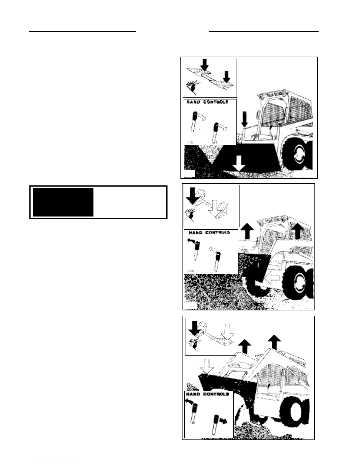
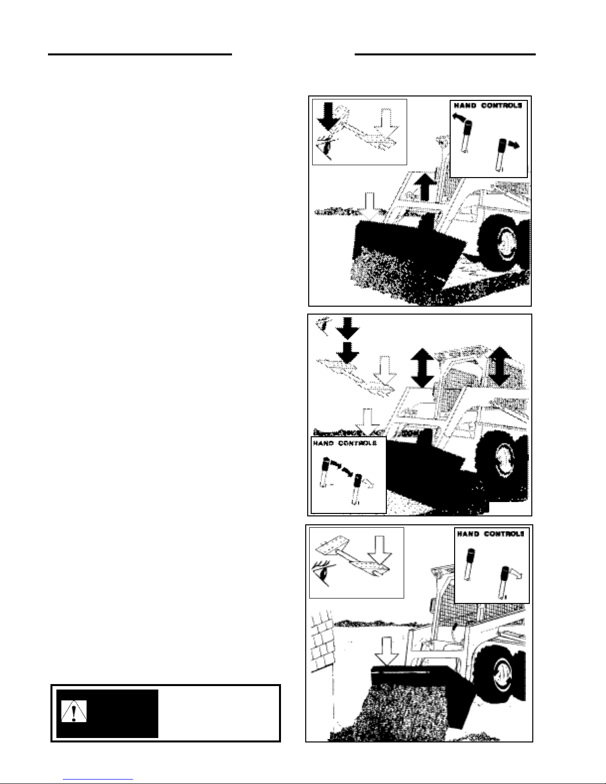
3. 3 FILLING FROM A PILE
Push down on the toe of the lift arm pedal and lower the lift
arms completely down (Fig. 3.3A). Push the toe of the bucket
pedal and place the cutting edge of the bucket on the ground.
For hand control units, move the L.H. control lever towards
you and lower the lift arms completely down. Move the R.H.
control lever away from you (Fig. 3.3A) and place the cutting
edge of the bucket on the ground.
Drive the loader forward slowly. As the bucket begins to fill
push on the heel of the bucket pedal to raise the front of the
bucket (Fig. 3.3B) and push on the heel of the lift arm pedal
to raise the lift arms. When the bucket is full back away from
the pile. For hand control units, move the R.H. control lever
towards you to raise the front of the bucket, and move the
L.H. control lever away from you to raise the lift arms (Fig.
3.3B). When the bucket is full back away from the pile.
To dump the bucket (Fig. 3.3C) push down on the heel of the
lift arm pedal to raise the lift arms. Push down on the toe of
the bucket pedal small amounts as the lift arms are raising to
stop material from falling off the back of the bucket. When
the bucket is at the correct height for dumping, push on the toe
of the bucket pedal to empty the bucket.
For hand control units, move the L.H. control lever away
from you (Fig. 3.3C) to raise the lift arms. Move the R.H.
control lever away from you in small amounts as the lift arms
are raising to stop material from falling from the back of the
bucket. When the bucket is at the correct height for dumping,
move the R.H. lever away from you to empty the bucket.
* Hand controls not available on all machines.
Always let the engine
warm completely before
you begin operation each
day.
IMPORTANT
3. OPERATION
Fig. 3.3A
Fig. 3.3B
C706
Fig. 3.3C
C709
C707
LH
R H
LH
RH
C710
LH
RH
*
*
*
Page 21

21
3. 4 DIGGING WITH A BUCKET
Push on the toe of the lift arm pedal and lower the lift arms
completely down. Push on the toe of the bucket pedal and
place the cutting edge of the bucket on the ground (Fig.
3.4D). Drive the loader forward at a slow rate and continue
to tilt the bucket down until it enters the ground.
Push down on the heel of the bucket pedal (Fig. 3.4E) to
increase traction and keep an even digging depth.
Continue to drive forward until the bucket is full. When
digging in hard ground, it is easier to raise and lower the
bucket cutting edge with the tilt pedal while slowly driving
forward. When the bucket is full, push down on the heel of
the bucket pedal (Fig. 3.4F) to raise the tip of the bucket.
For hand control units, move the L.H. control lever towards
you to lower the lift arms completely down. Move the R.H.
control lever away from you and place the cutting edge of the
bucket on the ground (Fig. 3.4D). Drive the loader forward at
a slow rate and continue to tilt the bucket down until it enters
the ground. Move the R.H. control lever towards you (Fig.
3.4E) to increase traction and keep an even digging depth.
Continue to drive forward until the bucket is full. When the
bucket is full, move the R.H. control lever towards you (Fig.
3.4F) to raise the tip of the bucket.
* Hand controls not available on all machines.
To avoid personal injury:
When starting or
operating loader in an
enclosed area make sure
there is enough
ventilation. Exhaust
fumes can kill.
WARNING
3. OPERATION
Fig. 3.4D
To prevent personal
injury always carry the
load low.
WARNING
Fig. 3.4E
C711
C713
Fig. 3. 4F
C715
LH
C712
RH
C714
LH
RH
C718
LH
RH
*
*
*
To prevent personal
injury, ensure that the
bucket with the proper
rated capacity is being
used for the job you are
doing.
WARNING
Page 22
22
3. 5 LEVELING AND BACKFILLING
Spread dirt on uneven ground by pushing on the heel of the lift
arm pedal (Fig. 3.5G) to raise the lift arms and push on the toe
of the bucket pedal to tilt the bucket down as you drive
forward.
For hand control units, spread dirt on uneven ground by
moving the L.H. control lever away from you (Fig. 3.5G).
This will raise the lift arms. Move the R.H. control lever away
from you to tilt the bucket down as you drive forward.
To level the ground; raise the lift arms and tilt the bucket down
by pressing on the toe of the bucket pedal. (See Fig. 3.5H)
Push firmly on the toe of the lift arm pedal to lock the lift arms
in the float position. The weight of the lift arms and bucket
will hold the bucket on the ground. Drive backward to level
material.
To level the ground with a hand control unit, raise the lift arms
and tilt the bucket down by moving the R.H. lever away from
you. Move the L.H. control lever all of the way towards you
(Fig. 3.5H) to place the lift arms in the float position. The
weight of the lift arms and the bucket will hold the bucket on
the ground. Drive backwards to level material.
To fill a hole (Fig. 3.5I) drive the loader slowly with the
bucket low, up to the hole. As the bucket passes the edge of the
hole, push on the toe of the bucket pedal to dump the bucket.
When necessary raise the lift arms to empty the bucket.
On hand control units, as the bucket passes the edge of the
hole, move the R.H. control lever away from you to dump the
bucket. When necessary, raise the lift arms to empty the
bucket.
* Hand controls not available on all machines.
3. OPERATION
Fig. 3.5H
C717
Fig. 3.5G
To prevent personal
injury always carry the
load low.
WARNING
C719
Fig. 3.5I
C721
C716
LH
RH
C720
LH
RH
C722
LH
RH
*
*
*
Page 23

23
3. 6 AUXILIARY HYDRAULICS
To operate an attachment such as a grapple fork the Left
Hand Control Lever will be used. Push right of neutral on
the Auxiliary Hydraulic Control Switch to open the
grapple (Fig. 3.6J).
To close the grapple (Fig. 3.6K), push left of neutral on the
Auxiliary Hydraulic Control Switch, or push down on the
toe of the auxiliary pedal if so equipped. The lift arm and
bucket pedals can be used to raise and tilt the grapple as
with a bucket.
To operate an attachment which requires a constant flow of
oil, a toggle switch on the L.H. instrument panel (Fig.
3.6L) should be placed in the “ON” position.
When the auxiliary circuit is not in use switch to the
“OFF” position. Otherwise starting the loader may be
difficult or impossible and damage to the starter may
occur.
Return the auxiliary
control to neutral when
not in use otherwise
starting may be
impossible and damage
to the starter may occur.
IMPORTANT
3. OPERATION
Fig. 3.6J
Fig. 3.6K
To avoid personal injury,
lower the lift arms, shut off
the engine, raise the seat bar
and cycle the hydraulics to
ensure they are locked. Then,
unlatch the seat belt and exit
the loader. Do not enter or
exit with the engine running
unless as specified in this
manual or under specific
service and backhoe
operating procedures.
WARNING
C723
C724
C3022
C3022
Fig. 3.6L
C3793
Toggle Switch
Page 24

24
3. 7 LIFTING
The loader is equipped with features to use in lifting (for
example by crane onto a flatbed trailer or a flat car), for
securing, and for extraction (from mud or snow). To
facilitate this requires the optional lifting lugs.
To lift using a crane, first follow the shut - off procedure in
section 3.1-3.
Once this is done, attach properly rated cables, chains or
straps to lift points provided (See Fig. 3.7). To prevent
marking the operator guard or chafing of the lifting cable,
a lifting frame should be used.
3. 8 TOWING
1. When winching or towing a stuck loader from the rear,
always lower the lift arms until the attachment is
resting on the ground and then follow the shut - off
procedure (See Section 3.1-3).
2. When winching or towing a stuck loader from the
front, lower the attachment so that the front attachment
points are accessible and have an assistant block the
attachment, then follow the shut-off procedure (See
Section 3.1-3).
3. Attach a properly rated chain, cable or towing strap to
the towing point provided (Fig. 3.8A).
4. Deactivate the brake system for towing. To release the
park brake, turn the release button on the brake valve
counter clockwise. Pressurize the brake release quick
coupler to 200 PSI (15 Bar). This will release the
motor brakes for towing. See maintenance section for
details.
5. Open the tandum pump by-pass valve which are
integral with the high pressure relief valves by turning
four (4) revolutions. There are four of the high
pressure relief valves. Two (2) on the top of the pump
(fig. 3.8B), and two (2) on the bottom. Do not open the
valves past four (4) turns. When open, the valve
connects both sides of the pump/motor circuit and
allows the motor to turn for towing short distances at
low speeds without running the engine. The valve
closing torque is 30 - 70 ft. lbs. (41 - 95 Nm.).
*Damage to the unit may result from over-torquing the
bypass valve.
6. The attachment point on the towing or winching
equipment should be kept as low as possible and in as
direct a line as possible with the stuck loader. A steep
tow line angle or side pull could result in upsetting the
stuck loader.
3. OPERATION
C3939
Fig. 3.8A
Fig. 3.7
C3407
To avoid personal injury,
lower the lift arms, shut off
the engine, raise the seat bar
and cycle the hydraulics to
ensure they are locked. Then,
unlatch the seat belt and exit
the loader. Do not enter or
exit with the engine running
unless as specified in this
manual or under specific
service and backhoe
operating procedures.
WARNING
IMPORTANT
Never install tie down
chains across the bucket
cylinders. Damage to the
cylinders may occur.
C1882
Fig. 3.8B
Bypass Valves (Top)
Page 25

25
3. OPERATION
3.9 SECURING AND TRANSPORTING
There are three tie down points provided for securing the
skid steer while transporting. One at the lower front and
two at the rear (Fig. 3.9).
Be sure the trailer and/or truck is of adequate size and
capacity to safely transport your skid steer.
Measure the clearance height of the machine and trailer or
truck, and post it in the cab of the truck.
Before loading the skid steer make sure the ramps and
parking surface are free of all oil, grease, ice, etc. and of
sufficient strength to support the load.
Know the local rules and regulations, and make sure your
truck and trailer is equipped with the correct safety
equipment.
When loading a skid steer with an attachment, always load
the heavy end first.
Once the skid steer has been loaded, lower the attachment
to the floor, stop the engine and engage the park brake.
Install chains at the front and rear tie down locations, and
securely attach to the transport vehicle.
NOTE: Minimum 3/8 in. grade 40 chain is required
C3408
Fig. 3.9
C362
SAFE SHUTDOWN PROCEDURES
- Stop machine
- Lower the bucket and other attachments flat on the
ground
- Position controls in neutral
- Raise operator seat bar to engage parking brake
- Idle engine for short cool-down period
- Stop engine
- Cycle all controls to ensure they are locked in
neutral
- Unbuckle seat belt
- Remove ignition key and lock covers and closures
C361
To avoid personal injury,
lower the lift arms, shut off
the engine, raise the seat bar
and cycle the hydraulics to
ensure they are locked.
Then, unlatch the seat belt
and exit the loader. Do not
enter or exit with the engine
running unless as specified
in this manual or under
specific service and backhoe
operating procedures.
WARNING
IMPORTANT
When moving your skid steer
on or off a transport vehicle,
drive slowly and keep the
machine centered.
WARNING
Ramps must be of sufficient
strength to support the
weight of your skid steer.
Wooden ramps can break
and cause personal injury.
Page 26

26
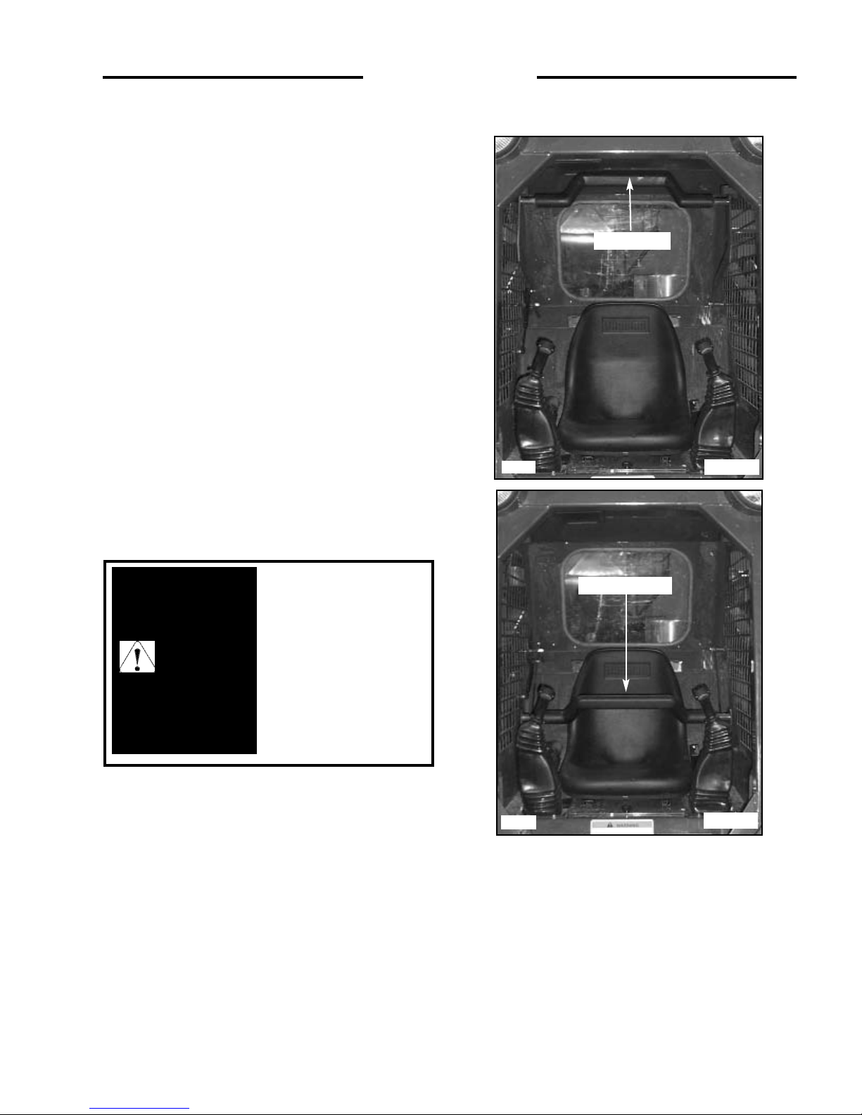
3.10 LOWERING LIFT ARMS
(ENGINE OFF)
In the event that you should have an electrical failure which
renders your skid steer inoperable with the lift arms up, the
following procedures would apply.
1. Lift Arm Height Is Sufficient To Engage
Lift Arm Support Pins
Engage lift arm support pins. (Fig. 3.10A) Raise seat bar
and cycle all controls to ensure they are locked. Exit loader
and open rear door. Locate the control valve on the left
side of the machine. Unplug the electrical wire and remove
the knurled nut holding the solenoid on the spool lock.
Remove the solenoid, then remove the lock pin and spring
assembly (Fig. 3.10C). Once the lock pin and spring are
removed, the lift arm spool is free to travel. Enter the
machine, being careful not to cycle the foot pedals or the
control levers as the locking system has been disabled.
Once in the operator seat dis-engage lift arm support pins.
Move the lift arm pedal or control lever to lower the lift
arms to the ground.
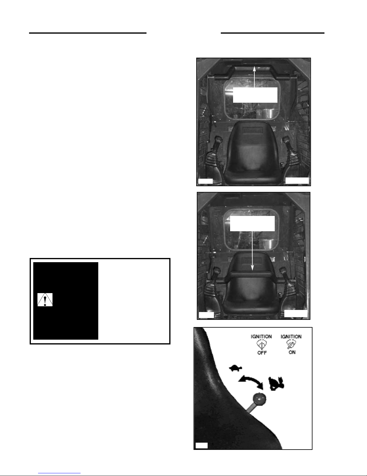
2. Lift Arm Height Is Not Sufficient To
Engage Lift Arm Support Pins
DO NOT EXIT FROM FRONT OF LOADER WITHOUT
LIFT-ARMS ON GROUND OR SUPPORTED BY
ACCEPTABLE MEANS!
Raise seat bar and cycle all controls to ensure they are
locked. If help is readily available, have some one place a
suitable support under the lift arms (e.g. 4” x 4” Lumber)
or a piece of angle iron between lift cylinder end cap and
lift cylinder rod mount.
Then exit loader using extreme caution. If help is not
available, the operator must exit the loader from the rear
window and perform the proper lift arm supporting (as
described previously). Once this is completed, open rear
door. Locate the control valve on the left side of the
machine (Fig. 3.10B). Unplug the electrical wire and
remove the knurled nut holding the solenoid on the spool
lock. Remove the solenoid, then remove the lock pin and
spring assembly (Fig. 3.10C). Once the lock pin and spring
are removed, the lift arm spool is free to travel.
Ensure assistance is available, then the operator can enter
the machine, being careful not to cycle the foot pedals or
the control levers as the locking system has been disabled.
Once in the operator seat, lower the safety bar. Have the
assistant remove the lift arm support devices. The operator
can then move the lift arm pedal or control lever to lower
the lift arms to the ground.
To avoid personal injury:
Do not leave lift arms up
unless the lift arm
supports are engaged.
WARNING
3. OPERATION
C-694
Fig. 3.10A
Fig. 3.10C
C805
Knurled
Nut
Lock Pin
Solenoid
C3413
Fig. 3.10B
Lift Arm Lock
Solenoid
C3949
Lift Arm Support
Spring
O-Ring
(underneith)
O-Ring
Page 27

3. OPERATION
3.11 ACCUMULATOR
The accumulator (fig. 3.11A) stores system pressure until
it is required to activate the electric auxiliary. The key
must be placed in the “On” position to operate the electric
auxiliary (engine not running).
The electric auxiliary and stored system pressure can be
used to activate the spools. This decreases the hydraulic
pressure from the male/female couplers located on the lift
arms. This is accomplished by cycling the momentary
switch on the L.H. control a couple of times (fig. 3.11B).
Once this pressure is decreased the operator can
remove/replace the quick attach accessories easily.
C3901
Fig. 3.11A
Accumulator
C3915
Fig. 3.11B
Momentary
Switch
ROPS SIDE
SEAT SIDE
27
Page 28

28
4. 1
Preventative Maintenance Service Schedule
4. 2 Service Access
1. Lift Arm Support
2. Seat Removal
3. Battery Access
4. Engine Compartment
4. 3 Daily Service Check
1. Hydraulic Oil Level
2. Air Cleaner
3. Tires and Wheel Nuts
4. Safety Equipment
5. Decals
6. Lubrication
7. Engine Oil Level
8. Radiator / Oil Cooler Service
4. 4 50 Hour Service Check
1. Engine
2. Hydraulic / Hydrostatic
3. Final Drive
4. Controls and Safety Equipment
5. Electrical
6. Grease / Lubrication
7. General
4. 5 150 Hour Service Check
4. 6 Final Drive Maintenance
1. Oil Level Check
2. Adding Oil
3. Drive Chain, Axle and Sprocket
Inspection
4. Chain Drive Adjustment
4. 7 Hydraulic / Hydrostatic System
Maintenance
1. Oil Level Check
2. Adding Oil
3. Hydraulic Filter Replacement
4. Draining System Fluid
5. Oil Cooler and Cooling Fan
6. Brake Service Override
4. 8 Engine Maintenance
1. Engine Maintenance
2. Oil Level Check
3. Engine Oil and Filter Replacement
4. Cooling System Fluid
5. V-Belt Tension
6. Adding Fuel
7. Fuel Filter Replacement
8. Bleeding the Fuel System
4. 9 Air Cleaner Maintenance
1. Daily Maintenance
2. Servicing Cleaner Element
4. 10 Engine Cooling System
4. 11 Electrical System
1. Battery Maintenance and Boosting
2. Electrical Schematic - ROPS
3. Electrical Schematic - Engine
4. 12 Tire Maintenance
1. Tire Inflation and Service
2. Tire Rotation
4. 13 Troubleshooting
1. Hydraulic System
2. Hydrostatic Drive
3. Final Drive Transmission
4. Control Levers
5. Electrical
6. Engine
4. 14 Hydraulic / Hydrostatic Cicuit
4.15 Special Tools
4. MAINTENANCE
4. MAINTENANCE
Page 29

29
ITEM SERVICE REQUIRED
8 HOURS
50 HOURS
150 HOURS
300 HOURS
1000 HOURS
Engine Oil
Hydraulic Oil
Radiator & Oil Cooler
Air Cleaner
Tires and Wheel Nuts
Safety Equipment
Decals
Lubrication
Hydraulic Oil Filter
Safety System Linkages
and Springs
50 Hour Service
Engine Oil
Engine Oil Filter
Final Drive
Hydraulic Oil Filter(s)
Preventative Maintenance
Service Check
Engine Oil
Engine Oil Filter
Check level and add if necessary. Use 10W30 API Classification CF oil.
Check level and add if necessary. Use10W30 API Classification SJ or
20W50 API Classification SJ oil.
Check level and add if necessary. Fill with 50% mixture of ethylene
glycol and water. Check cooling fins for dirt. If necessary blow out with
compressed air.
Empty dust cap. Check condition indicator and service or replace element
as required.
Check for low pressure or tire damage, refer to Section 5.1 for more
information. Check wheel nut torque 100-110 ft. lbs. (136-149 Nm).
Check all safety equipment for proper operation and condition. Seat belt,
lift arm supports, quick-tach locks, parking brake, safety treads, front
shield and cab side screens. If necessary lubricate foot pedal and steering
control linkages, springs and shafts with a silicone based lubricant. If
necessary repair or replace.
Check for damaged safety or instruction decals (See Section 5.3). If
necessary replace.
Grease all hinge pin fittings and pivot bearings until excess shows.
Replace hydraulic oil filter element. Initial change only.
Check and if necessary adjust. Lubricate lock springs, shaft and linkage
with a silicone based lubricant.
Perform complete 50 hour service (See Section 4.4).
Replace engine oil. Use API Classification CF oil. (See Section 4.8-3).
Initial change only.
Replace engine oil filter. Initial change only.
Check chain and sprocket condition. Check every 150 hours.
Replace hydraulic oil filter element (See 4.7-3).
It is recommended as a preventative maintenance procedure that the 50
hour service be repeated every 150 hours. (See Section 4.5)
Replace engine oil. Use API Classification CF oil. See 4.8-3. Replace
every 150 hours.
Replace engine oil filter. See 4.8-3. Replace every 300 hours.
4.1 PREVENTIVE MAINTENANCE SERVICE SCHEDULE
4. MAINTENANCE
Page 30

30
WARNING
ITEM SERVICE REQUIRED
50 HOURS
150 HOURS
300 HOURS
800 HOURS
1000 HOURS
Engine Fuel Filter
Engine Valve Clearance
Final Drive
Hydraulic reservoir
Engine Cooling System
Replace engine fuel filter. (See Section 4.8-6).
Adjust (See Thomas Dealer).
Change final drive lubricating oil. Use 10W30 API Classification SJ oil.
Remove and replace the 100 micron suction element in the oil reservoir.
Change hydraulic oil. Replace with 10W30 API Classification SJ oil or
20W50 API Classification SJ.
Drain, flush and refill. Use 50% mixture of ethylene glycol and water.
To avoid personal injury
service repairs must be
performed by an
authorized Thomas
dealer.
4. MAINTENANCE
WARNING
WARNING: Escaping hydraulic
fluid under pressure can
penetrate the skin causing
serious injury.
• DO NOT use your hand to check
for leaks. Use a piece of cardboard
or paper to search for leaks.
• Stop engine and relieve pressure
before connecting or disconnecting
lines.
• Tighten all connections before
starting engine or pressurizing
lines.
If any fluid is injected into the skin
obtain medical attention
immediately of gangrene may
result.
Page 31

31
4. 2 SERVICE ACCESS
1. Lift Arm Support
For safety while performing regular service or
maintenance work, the loader is equipped with lift arm
support pins. The lift arm support pins when extended
prevent the lift arms from dropping if hydraulic pressure is
relieved or the hydraulic controls are accidentally cycled.
To operate the lift arm support, first remove any bucket or
attachment from the quick-tach; raise the lift arms to full
height. Raise the lift arm support handle (Fig. 4.2A) up and
push out toward lift arms to extend the lift arm supports.
(Fig. 4.2B) Slowly lower the lift arms down on to the pins.
To retract the lift arm supports, lift the lift arms off of the
pins before retracting pins.
2. Seat Removal
The seat assembly can be removed to provide access to the
controls, hydraulic and hydrostatic components. To
remove the seat assembly, remove the fasteners located at
the front of the seat. DISCONNECT ELECTRICAL
PLUG! Lift the seat assembly out of the machine. When
installing the seat, be sure the seat plate is locked in place
at the rear (Fig. 4.2C).
3. Battery Access
The battery is located in a compartment found behind the
operators seat (Fig. 4.2D). Remove the seat and remove
the bolt holding the battery cover in place. The battery
compartment is hinged with a prop rod to hold open.
Fully retract lift support
pins before raising or
lowering lift arms.
IMPORTANT
To avoid personal injury:
Do not leave lift arms up
unless the lift arm
supports are engaged.
WARNING
4. MAINTENANCE
Fig. 4.2C
Fig. 4.2B
C1132
C694
Electrical Plug
C3135
Fig. 4.2A
Fig. 4.2D
C4417
Page 32

32
4. Engine Compartment
The engine compartment is completely enclosed for
component protection and lockable to discourage
vandalism. For servicing the rear door swings open and
the engine cover hinges up.
To open; raise the door lock handle up over the lock plate;
pull outward releasing the door catch and swing the door
open (Fig. 4.2E). Lower the engine cover before closing
the rear door. Figure 4.2F shows the engine compartment.
4. 3 DAILY SERVICE CHECK
1. Hydraulic Oil Level
Check the oil level with the machine on a level surface
with the lift arms down and the attachment grounded.
Open the rear door and check the oil level sight glass (Fig.
4.3A). If oil is apparent the oil level is satisfactory.
If necessary to add oil, remove the reservoir cap located
at the top of the oil reservoir and add oil until oil appears
in the oil level sight glass.
Use a good quality 10W30 oil which meets the API
classification SH only.
2. Air Cleaner
The loader is equipped with an air cleaner restriction
warning lamp. Should this lamp illuminate, shut off the
engine and determine cause. Possibly a plugged air filter.
Figure 4.3B shows the air cleaner.
Check that all hose clamps are tight and the hose is
undamaged. Check the vacuator valve for damage (Fig
4.3B).
See Section 4.9 for Air Cleaner Maintenance.
Fig. 4.2F
C1866
Keep the rear door
closed except for
servicing. Make sure the
door is closed and
latched before operating
the loader.
IMPORTANT
4. MAINTENANCE
C644
Fig. 4.3A
C674
Fig. 4.2E
WARNING
To avoid personal injury:
Stop, Cool and Clean the
engine of flammable
materials before
servicing. Never service
or adjust machine with
engine running.
Fig. 4.3B
C1237
Air Cleaner
Vacuator Valve
Page 33

33
3. Tires and Wheel Nuts
Inspect tires for wear or damage. Check and inflate tires to
correct pressure:
10.00 x 16.5 ...........40 - 45 PSI (276 - 310 kPa)
Tires can be inflated to 50 PSI (345 kPa) when operating
on hard, flat surfaces.
To prevent shearing of the wheel studs and rim damage
check wheel nuts for proper torque 100 -110 lbs. ft. (136 149 Nm) daily (Fig. 4.3C). After changing a rim, Check
wheel nuts hourly, until the reading stabilizes.
4. Safety Equipment
Check all safety equipment for proper operation and
condition - seat belt, lift arm supports, seat bar, steering
neutral lock, parking brake, quick tach lock, shields,
safety treads and lift arm lock down. Lubricate all
linkages, springs and pivot points with a silicone based
lubricant. Repair or replace if necessary.
5. Decals
Check the condition of all safety and instruction decals.
Replace any damaged or missing decals. Refer to Section
5.3 for decal description and locations.
6. Lubrication
There are sixteen (16) grease fittings located in the loader
that require lubrication every eight hours. Lubricate with
a good quality multi-purpose lithium based grease. Apply
grease until excess shows. Refer to the service schedule
for complete service details. (See Fig. 4.3D). The sixteen
(16) lubrication points are:
Rear Lift Arm Pivots (2)
Lift Cylinder Bushings (4)
Bucket Cylinder Bushings (4)
Lift Arm Supports (2)
Quick Tach Pivot and Lock Pins (4)
7. Engine Oil Level
Check the oil before engine start up. If the engine has been
running let it cool for at least 5 minutes to allow the oil to
drain back to the oil pan.
To check the oil level, check with the loader on level
ground, open the rear door and remove the dipstick (Fig.
4.3E).
Keep the oil level between the full and low mark on the
dipstick (Fig. 4.3F). Do not fill above the full mark. Use
API Classification CF oil.
4. MAINTENANCE
C3956
Fig. 4.3D
Torque Wheel Nuts 100 - 110 lbs. ft. (136 - 149 Nm)
Fig. 4.3C
C3415
Fig. 4.3E
Dipstick
Location
C3414
Fig. 4.3F
FULL
LOW
Page 34

34
8. Radiator / Oil Cooler Service
With the engine cool, check the coolant level in the
overflow reservoir (fig. 4.3G). Ensure the coolant level is
at the Full-Cold mark on the reservoir by adding 50%
mixture of ethylene glycol and water if required.
The radiator and oil cooler fins must be kept free of debris
otherwise overheating of the engine will occur. Inspect the
radiator cooling fins for damage or buildup of debris.
Repair any damage and if necessary flush the radiator
with compressed air to remove debris.
4. 4 50 HOUR SERVICE CHECK
The following service check is to be performed by your
dealer after the first 50 hours of operation.
1 Engine
1.1 Oil and Filter:
Change the engine oil and filter. Use only original
replacement parts. Change the oil every 150 hours
thereafter. Change the filter every 300 hours
thereafter.
1.2 Radiator:
Check the coolant level. If necessary flush the radiator
with compressed air. A dirt buildup on the radiator
cooling fins can cause both engine and hydraulic
system overheating. Check the foam sealing ring on
the fan drive.
1.3 V-Belt Tension and Condition:
Check v-belt for cuts or wear, if necessary replace.
Check tension and adjust as shown in Section 4.8.4.
1.4 Fuel System for Leaks:
Make a visual inspection of fuel system for leaks and
potential hazards such as fuel line(s) touching exhaust
manifold, flywheel, etc. Replace fuel filter every 300
hours.
1.5 Air Intake and Cleaner System:
Visually inspect the air cleaner system and be sure all
hose clamps are secure and no hoses are damaged.
1.6 Exhaust System:
Visually inspect the exhaust system and ensure all
clamps are secure and the manifold bolts/nuts are tight.
1.7 Engine Speed:
Check engine speed and if adjustment is necessary,
contact a Thomas Equipment dealer.
4. MAINTENANCE
Keep the rear door
closed except for
servicing. Make sure the
door is closed and
latched before operating
the loader.
IMPORTANT
To avoid personal injury,
lower the lift arms, shut off
the engine, raise the seat bar
and cycle the hydraulics to
ensure they are locked. Then,
unlatch the seat belt and exit
the loader. Do not enter or
exit with the engine running
unless as specified in this
manual or under specific
service and backhoe
operating procedures.
WARNING
Coolant Overflow
Reservoir
C1663
Fig. 4.3G
Page 35

35
2 Hydraulic/Hydrostatic
2.1 Hydraulic Oil Filter:
Change the hydraulic filter now and every 150 hours
after the initial change. Lubricate the filter cartridge
seal with system fluid.
2. 2 Hydraulic Oil Level:
If oil is visible in the oil level sight glass the level
satisfactory.
If additional oil is required use only 10W30 API
classification SJ oil. Fill to the top or maximum
check point.
2.3 Hoses and Pipes:
Make a visual inspection of all hydraulic lines and
fittings for leaks. Check that steel lines do not touch
one another.
2.4 Cylinders:
Inspect cylinders for leaks. Extend cylinders and
check for rod damage.
2.5 Hydraulic Functions:
Check that the following operate properly: control
valve float position, auxiliary hydraulics, pedals and
hydraulic cylinders.
2.6 Pumps & Motors, Leakage:
Inspect pumps and motors for leaks.
2.7 Oil Cooler:
Inspect the oil cooler for leaks, fin damage or clogged
with dirt. If necessary flush fins with compressed air.
2.8 Fan Drive:
Inspect fan, bolts, v-belt and guard to ensure there is
no buildup of dirt, trash, or wear. Use compressed air
to clean the area.
3 Final Drive
3.1 Oil Level:
Check lubricating oil level. If necessary add 10W30
API classification SJ oil.
3.2 Drive Chain Condition:
Check drive chains for any sign of wear or damage.
Check lubrication oil in housing for signs of
contamination.
3.3 Hydrostatic Motor Mounting Bolts:
Check torque 85 - 90 ft. lbs. (115 - 122 Nm)
3.4 Bearing End Play:
Check both the idler sprocket and axle bearings for
loss of bearing pre-load. If necessary, adjust the
bearings for zero end play.
3.5 Axle Seal:
Inspect axle seal area. Clean area of debris build up
and visually check for seal damage, replace as
required.
4 Controls and Safety Equipment
4.1 Control Levers, Operation and Linkage:
Check that the steering levers operate freely without
binding, they return to neutral when released and the
machine travels in a straight line with both levers in
forward position. Ensure control levers lock in neutral
with seat bar up. Lubricate linkage with a silicone
based lubricant.
4.2 Hydraulic Controls, Operation and Linkage:
Check that the hydraulic controls, foot pedals or hand
controls operate freely without binding. Before leaving
the operator seat, ensure the controls are locked.
Seat Bar Switch Check: Raise the seat bar and check that the
hydraulic controls are locked in neutral.
Seat Belt Switch Check:
Unbuckle the seat belt and check
that the hydraulic controls are locked in neutral.
Seat Switch Check: With the seat bar down and the seat belt
connected loosely around you, raise your weight off
the seat and check that the controls are locked in
neutral.
4.3 Engine Throttle Control:
Check that the throttle control operates freely without
binding or slackening off due to vibration.
4. 4 Parking Brake:
Check that the parking brake engages and completely
disengages. The park brake automatically engages with
seat bar up.
4. 5 Lift Arm Supports:
Check that the lift arm supports operate without
binding.
NOTE: Ensure the lift arm supports are fully retracted
before raising or lowering the lift arms.
4. MAINTENANCE
WARNING
To avoid personal injury:
never repair or tighten
hydraulic hoses or
fittings with the engine
running or the system
under pressure.
Page 36

36
4.6 Quick-Tach, Operation & Linkage:
Ensure the quick-tach linkage operates smoothly
without binding and engage completely.
4.7 Seat Belt:
Check seat belt condition. If necessary replace.
5 Electrical
5.1 Battery (s):
Maintenance Free.
5.2 Battery Terminals:
Check battery terminals for corrosion. If necessary,
clean.
5.3 Starter Operation:
Engage and disengage the starter a few times to ensure
it’s working properly. To prevent starter damage do not
engage for more than 15 seconds. Allow 1 minute
between starting attempts for cooling the starter and
stop solenoid.
5.4 Operation of Electrical Equipment:
Make a complete check of all electrical equipment,
gauges, warning devices, pre- heater indicator, work
lights, seat and seat belt switch, seat bar switch and all
optional equipment to ensure they are operating
correctly.
6 Grease/Lubrication
Lubricate the following points with a good quality
grease. Numbers marked ( ) indicate the number of
fittings at each location.
Rear Lift Arm Pivots (2)
Lift Arm Cylinder Bushings (4)
Bucket Cylinder Bushings (4)
Engine Universal Joint (2)
Lift Arm Supports (2)
Quick - Tach Pivot (4)
7 General
7. 1 Tire Pressure:
Check tire pressure and if necessary inflate to the
following pressures:
10.00 x 16.5 . . . . . . . 40 - 45 PSI (207 - 241 kPa)
7. 2 Wheel Nut Torque:
Check and torque wheel nuts to 100 - 110 ft. lbs. (136
- 149 Nm).
7.3 Condition of Cab:
Inspect both the seat and seat belt. Ensure all safety and
instruction decals are in place. Inspect sound
insulation, side windows and door operation for
machines equipped with cab enclosure kits. Inspect for
structural damage and alterations to R.O.P.S.
7. 4 Condition of Shields and Safety Equipment:
Inspect and ensure all shields are in place and
securely fastened. Inspect and ensure all safety
equipment is working properly. Ensure owners and
operators manual,
safety manual and all safety and
instruction decals are in place. If necessary, replace.
If the safety controls are malfunctioning or require
adjustment, consult a Thomas Equipment Dealer for
service.
7. 5 General Condition:
Make a general inspection of the machine looking for
loose or missing parts, oil leaks, etc.
4. 5 150 HOUR SERVICE CHECK
The following service check is to be performed by your
dealer after the first 150 hours of operation.
1. It is recommended that the 50 hour check (see
Section 4.4) be repeated at 150 hours.
4. MAINTENANCE
Page 37

37
4. 6 FINAL DRIVE MAINTENANCE
1. Oil Level Check
The loader has two independent final drive housings.
Check the lubricating oil level with the loader on a level
surface. Remove the check plug (Fig. 4.6A) located on the
front of the loader to determine the oil level. The oil level
should be checked after 50 operating hours and every 150
hours thereafter. It is recommended the oil be changed
after 1000 operating hours or if it shows signs of
contamination.
2. Adding Oil
Add oil with the loader on level ground. Remove the oil
level check plug (Fig. 4.6A) on the final drive housing.
Remove the seat and hydrostatic shield. Remove the filler
cap (Fig. 4.6B). Fill with 10W30 API Classification SJ to
the level of the check plug.
3. Drive Chain, Axle and Sprocket Inspection
The condition of the drive chains should be checked after the
first 50 hours of operation and every 150 hours thereafter.
To inspect, block the loader securely with all four wheels
off the ground. Remove both the front and rear wheels. On
reassembly torque the wheel nuts to 100-110 ft. lbs. (136149 N m). Remove the inspection cover on the side of the
chain drive housing.
Inspect the chain for any sign of wear, damage or excessive
looseness. Inspect the sprockets for any sign of damage or
excessive wear. Inspect the lubricating oil for signs of
contamination. Check both the idler sprocket and axle
bearings for loss of bearing preload. If necessary adjust the
bearings for zero end play.
Check the axle seals for leaking oil or damage. Replace
seals at first sign of problem.
4. MAINTENANCE
Check Plug
Fig. 4.6A
C1033
Filler Cap
Fig. 4.6B
C1662
Page 38

38
4. Chain Drive Adjustment
The drive chain must be checked for excessive slack after
the first 50 hours of operation and every 150 hours
thereafter.
To adjust, remove the inspection cover on the seat support.
With the parking brake engaged, remove the filler cap and
measure the amount of free play in the chain with the
chain tension gauge (Fig. 4.6C). The chain must be
adjusted so there is between 1/4 - 3/8 inch (6.4 - 9.5 mm)
free play.
Remove the shield protecting the chain tightener.
Loosen the 3 chain tightener nuts (Fig. 4.6D), until the
spring washers just begin to open. do not over-loosen or
over tightening of the chain can occur.
Back off the rear adjuster nut (Fig. 4.6D) and tighten the
front adjustment nut until free play measured on the chain
is between 1/ 4 - 3/8” (6. 4 - 9.5 mm).
Tighten the rear adjuster nut and torque the 3 chain
tightener nuts to 150 ft. lbs. (203 Nm) (Fig. 4.6D).
Repeat on opposite side of machine.
4. 7 HYDRAULIC/ HYDROSTATIC
SYSTEM MAINTENANCE
1. Oil Level Check
Check the oil level of the hydraulic reservoir with the
machine on a level surface with the lift arms down and the
attachment grounded. Shut off the engine. Open the rear
door and check the oil level sight glass (Fig. 4.7A). If oil
is apparent the level is satisfactory.
WARNING
WARNING: Escaping hydraulic
fluid under pressure can
penetrate the skin causing
serious injury.
• DO NOT use your hand to check
for leaks. Use a piece of cardboard
or paper to search for leaks.
• Stop engine and relieve pressure
before connecting or disconnecting
lines.
• Tighten all connections before
starting engine or pressurizing
lines.
If any fluid is injected into the skin
obtain medical attention
immediately of gangrene may
result.
Front
Axle
Rear
Axle
4. MAINTENANCE
C644
Fig. 4.7A
Fig. 4.6D
C-1037
Fig. 4.6C
C372
Chain Tension
Guage
Oil Level
Sight Glass
Adjustment Nuts
Chain Tightener Nuts
Page 39

39
2. Adding Oil
To add oil, remove the oil filler cap located at the top of the
oil reservoir (Fig. 4.7B). Check and ensure the filter screen in
the filler neck is undamaged. Add 10W30 or 20W50API
Classification SJ oil until oil is visible in the oil level sight
glass (Fig. 4.7A).
3. Hydraulic Filter Replacement
The hydraulic oil filter (Fig. 4.7C) must be changed after
the first 50 hours of operation and every 150 hours
thereafter.
To change the filter; shut off the engine, lower the lift
arms, ground any attachment and set the parking brake.
Open the rear door and using an oil filter wrench remove
the filter element. Lubricate the new filter seal with system
fluid and reinstall hand tight. Note: The loader only has
one filter.
4. Draining System Fluid
Change the hydraulic oil:
1. After 1000 operating hours.
2. If the oil has become contaminated.
3. After any major hydrostatic repair.
To drain the oil: remove the drain plug located at the
bottom of the reservoir (Fig. 4.7D). Have a container(s)
ready to hold approximately 15 gallons (58 liters) of
fluid. Remove any metal particles stuck to the magnet.
Seal the plug with teflon tape when replacing.
4. MAINTENANCE
To avoid personal injury,
lower the lift arms, shut off
the engine, raise the seat bar
and cycle the hydraulics to
ensure they are locked. Then,
unlatch the seat belt and exit
the loader. Do not enter or
exit with the engine running
unless as specified in this
manual or under specific
service and backhoe
operating procedures.
WARNING
OIL RESERVOIR
DRAIN
Fig. 4.7B
Fig. 4.7D
C1034
C-1108
Thomas recommends
that you abide by all
applicable enviromental
regulations when
disposing of oil.
IMPORTANT
OIL FILLER CAP
C3364
Fig. 4.7C
Hydraulic
Filter
Page 40

5. Oil Cooler and Cooling Fan
Oil returning from the control valve is circulated through
the oil cooler before being sent to other parts of the
hydraulic system.
An engine cooling fan drives air through the oil cooler
when the rear door is closed. Refer to Figure 4.7E.
The oil cooler should be checked daily for dirt buildup on
the cooling fins. If the air flow is restricted through the
cooling fins, overheating of the hydraulic system may
occur. Clean any dirt buildup with compressed air. Flush
with water if necessary. Figure 4.7E shows the radiator/oil
cooler setup for the loader.
6. Brake Service Override
A service override has been incorporated for use by
Thomas Dealers. The normal position of the plunger is
down and turned into the locked position (Fig. 4.7F).
To release the park brake, turn the release button counter
clockwise. Go to the rear of the machine and pressurize the
small quick coupler to 200 psi to release the park brake
(Fig. 4.7G).
4. MAINTENANCE
Fig. 4.7E
C3416
Oil Cooler
Fan
To avoid eye injury
always use safety goggles
when cleaning with
compressed air.
WARNING
Fig. 4.7F
C1255
40
C1663
Fig. 4.7G
Brake Quick
Coupler
Plunger
Page 41

41
2. Oil Level Check
Check the oil before engine start up. If the engine has been
running let it cool for at least 5 minutes.
To check the oil level, stop the engine with the loader on
level ground, open the rear door and remove the dipstick
(Fig. 4.8A).
Keep the oil level between the full and low mark on the
dipstick. Do not fill above the full mark.
3. Engine Oil and Filter Replacement
Operate the engine until warm, approximately 5 minutes.
Stop the engine. Remove the oil drain plug located at the
bottom of the oil pan. Remove the oil filter (Fig. 4.8B).
Clean the filter housing surface. Put clean oil on the seal of
the new filter and install the filter hand tight.
Replace the oil drain plug. Remove the filler cap and add
10W30 API classification CF engine oil. Start the engine
and run for 5 minutes. Stop the engine and check for leaks
at the filter. Recheck the oil level and add oil until the level
is at the top mark on the dipstick.
WARNING
To avoid personal injury:
Stop, Cool and Clean the
engine of flammable
materials before
servicing. Never service
or adjust machine with
engine running.
4. MAINTENANCE
C3415
Fig. 4.8A
Dipstick
Location
C828
Fig. 4.8B
Engine Oil
Filter
Thomas recommends
that you abide by all
applicable enviromental
regulations when
disposing of oil.
IMPORTANT
4. 8 ENGINE MAINTENANCE
1. Engine Specifications 153 135TA/137
Make............................................................................................Kubota............................................Kubota
Model...........................................................................................V2203E..........................................V1903E
No. of Cyls ..................................................................................4......................................................4
Horsepower (Gross) ....................................................................49....................................................42
Power (ISO9249 Net Power) ......................................................34.3 kW...........................................29kW
Power CE (ISO9249 Net Power) ................................................33.8 kW...........................................28.9kW
High Idle............................................................................. ........2800................................................2800
High Idle CE ...............................................................................2600................................................2600
Max. Torque.................................................................115 ft.lbs. (15.9kg/m@1600)............89.1 ft.lbs. (12.3 kg/m @ 1600)
Displacement ...................................................................... 134 in.
3
(2197 c.c.)..........................113.5 in.3(1861 c.c.)
Engine Oil ...................................................................................8.5 qts. (8 L)...................................8.5 qts. (8 L)
Firing Order.................................................................................1 - 3 - 4 - 2......................................1 - 3 - 4 - 2
Alternator.....................................................................................40 A.................................................40 A
Oil Check.....................................................................................Daily................................................Daily
Oil Change...................................................................................150 hrs............................................150 hrs.
Filter Change ...............................................................................150 hrs............................................150 hrs.
Page 42

4. V-Belt Tension
Check the V-belt tension midway between the crankshaft
pulley and alternator pulley (Fig. 4.8C). Deflection should
be between 1/4 to 3/8 in. (7-9 mm).
5. Adding Fuel
Use No. 2 diesel fuel only. Total tank capacity 18 gal. (68
L). Before adding fuel to the loader the key switch must
be off and the engine must be cool. Remove the fuel cap
(Fig. 4.8D). Use a clean approved safety container to add
fuel. Add fuel only in an area that is well ventilated and
away from open flames or sparks - NO SMOKING!
6. Fuel Filter Replacement
The fuel filter is located in the engine compartment on the
left hand side (Fig. 4.8E). The fuel filter should be
removed every 100 hours and any water or dirt found in
the element drained off. Change the filter every 300 hours.
To replace the filter; close the fuel inlet line shut - off
located on the side of the fuel tank (Fig. 4.8E). Remove the
filter element (Fig. 4.8E). Lubricate the seal on the new
filter and install the filter hand tight. Open the fuel inlet
shut - off. It may be necessary to remove air from the fuel
system after changing the filter element. (Refer to Section
4.8-8).
7. Bleeding the Fuel System
Air must be removed from the fuel, after replacement of
the fuel filter element, or when the tank has been run out
of fuel, before starting the engine.
To remove air, ensure the fuel inlet shut-off located on the
side of the fuel tank is open (fig. 4.8E). Open the bleed
valve by turning it counter clockwise (fig. 4.8F) on top of
the injector pump. Place the throttle at idle, then turn the
engine over with the starter. After the engine starts and
runs smoothly, shut off the engine and close the bleed
valve by turning it clockwise.
Fuel Filter
Fig 4.8E
Fuel Inlet Shut - off
C-831P
C-1238
Fig. 4.8F
C-833
Fuel Air
Bleed Valve
4. MAINTENANCE
Alternator
Pulley
Fan Pulley
Crankshaft Pulley
Fig. 4.8C
C-834
Fuel Tank
C1254
Fig.4.8D
WARNING
To avoid personal injury
never add fuel to the
loader when the engine is
running or is hot. NO
SMOKING.
42
Page 43

4. 9 AIR CLEANER MAINTENANCE
1. Daily Maintenance
Inspect the air cleaner canister for holes, dents,
missing or mis-aligned gaskets. Check all hose
clamps for tightness and inspect the hose and
vacuator valve for damage (Fig. 4.9A).
2. Servicing Cleaner Element (Fig. 4.9B)
DO NOT open unless the indicator indicates a blocked
filter or under normal scheduled servicing. To check
the indicator, with the engine running, block half of the
intake inlet and check the indicator on the dash panel.
It should illuminate to simulate a blocked filter.
2.1 Unlatch and remove the cover assembly
2.2 Release The Seal Gently - The filter should be
removed gently to reduce the amount of dust
dislodged. Move the end of the filter up and down
and side to side or twist to break the seal.
2.3 Avoid Dislodging Dust from the Filter - Gently pull
the filter off the outlet tube. Avoid knocking the
filter against the housing.
2.4 Always clean the sealing surface of the outlet tube
- Dust on the outside diameter of the housing could
hinder an effective seal.
2.5 Always clean the inside of the outlet tube. Dirt
inside of the outlet tube will reach the engine : it
only takes 9 grams of dirt to dust an engine.
2.6 Check your old filter. Inspecting your old filter will
detect foreign material on the sealing surface that
may causing leakage.
2.7 Inspect the new filter for seal or pleat damage.
2.8 Insert the new filter properly - The seal area is on
the inside of the open end of the primary filter. A
new filter has a dry lubricant to aid installation. The
critical sealing area will stretch slightly, adjust
itself and distribute the sealing pressure evenly. To
complete a tight seal, apply pressure at the outer
rim of the filter, not the flexible centre. No cover
pressure is required to hold the seal.
2.9 Check connections and ducts for air tight fit - Make
sure all clamps, bolts and connections are tight.
Check for holes in piping. Leaks here send dust
directly to the engine.
2.10 DO NOT reuse filters by cleaning and reinserting.
4. MAINTENANCE
To avoid personal injury,
lower the lift arms, shut off
the engine, raise the seat bar
and cycle the hydraulics to
ensure they are locked. Then,
unlatch the seat belt and exit
the loader. Do not enter or
exit with the engine running
unless as specified in this
manual or under specific
service and backhoe
operating procedures.
WARNING
To avoid personal
injury: DO NOT charge
a frozen battery because
it can explode and cause
personal injury. Let the
battery warm to
60°F.(15.5°C.) before
putting on a charger.
WARNING
Inlet
Outlet
Cover Assembly
Vacuator
Valve
Latch
Safety
Filter
(Optional)
Primary
Filter
C-653
Fig. 4.9B
43
Fig 4.9A
C3417
Air Cleaner
Hose
Vacuator Valve
Page 44

4. 10 ENGINE COOLING SYSTEM
The engine cooling system fluid is a 50-50 mixture of
ethylene glycol and water for cold-weather protection.
To drain the cooling system; attach a hose to the drain
valve located at the engine block (Fig. 4.10A). Remove
the radiator cap. Turn the drain valve handle so that it’s
toward the valve outlet. To completely drain the radiator
remove the rubber drain plug located at the bottom of the
radiator (Fig. 4.10B). To fill the cooling system; close the
drain valve on the engine block (Fig. 4.10A) and refit the
radiator drain plug. Fill the radiator with a 50-50 mixture
of ethylene glycol and water. Refit the radiator cap.
C3418
Fig. 4.10A
WARNING
To avoid personal injury:
DO NOT remove the
radiator cap when the
engine is hot.
4. MAINTENANCE
44
Engine Coolant
Drain
Drain Valve
Handle
C3419
Fig. 4.10B
Rubber Drain
Plug
WARNING
To avoid personal injury
never add coolant when
the engine is running or
is hot.
Page 45

4. 11 ELECTRICAL SYSTEM
1. Battery Maintenance and Boosting
Inspect the batteries on a regular basis for damage such as
a cracked or broken case or cover which would allow
electrolyte loss.
Check the battery cables for tightness and corrosion.
Remove any acid corrosion from the battery and cables
with a baking soda and water solution. Coat the terminal
connections with di-electric grease.
If it is necessary to use a booster battery to start the engine,
BE CAREFUL! There must be one person in the operators
seat and one person to connect and disconnect the battery
cables.
BOOSTING PROCEDURES
The ignition must be in the OFF position. The booster
battery to be used must be 12 volt. Connect the end of the
first cable to the positive (+) terminal of the booster battery.
Connect the other end of the same cable to the loader
battery positive (+) terminal. Connect the end of the
second cable to the negative (–) terminal of the booster
battery (fig. 4.11A). Connect the other end of the same
cable to a ground. Keep cables away from moving parts.
Start the engine. After the engine has started, disconnect the
end of the second cable from the negative (–) terminal of
the booster battery. Disconnect the other end of the same
cable from the ground. Disconnect the end of the first cable
from the positive (+) terminal of the booster battery.
Disconnect the other end of the same cable from the loader
battery positive (+) terminal.
4. MAINTENANCE
WARNING
To prevent personal injury
DO NOT charge a frozen
battery because it can
explode and cause
personal injury. Let the
battery warm to 60°F.
(15.5°C.) before putting on
a charger.
Lead-acid batteries contain
sulfuric acid which will
damage the eyes or skin on
contact. Always wear goggles
to avoid acid in the eyes. If
acid contacts the eyes, wash
immediately with LARGE
QUANTITIES of clean water
and get medical attention.
Wear rubber gloves and
protective clothing to keep
acid off the skin. If acid
contacts the skin, wash off
immediately with clean water.
WARNING
45
C3419
Fig. 4.11A
Boosting Lug
Page 46

46
2. ELECTRICAL SCHEMATIC – ROPS
4. MAINTENANCE
C3361
Page 47

47
3. ELECTRICAL SCHEMATIC – ENGINE
4. MAINTENANCE
C3690
Page 48

4. 12 TIRE MAINTENANCE
1. Tire Inflation and Service
1.1 Upon receiving your loader, check the air pressure
in the tires as indicated in the tables.
1.2 Check tire pressure every 8 hours.
1.3 Tire inflation pressure affects the amount of
weight which a tire may carry. Do not over-orunder inflate the tires.
1.4 Do not inflate a tire above the manufacturer’s
maximum pressure shown on the tire or the
maximum pressure shown in the table.
1.5 Do not re-inflate a tire that has been run flat or
seriously under-inflated until the tire has been
inspected for damage by a qualified person.
1.6 When checking tire pressure, inspect the tire for
damaged side walls and tread cuts. Neglected
damage will lead to early tire failure.
1.7 Be sure the rim is clean and free of rust.
1.8 Lubricate both tire beads and rim flanges with
soap solution. Do not use oil or grease.
1.9 Use a clip-on tire chuck with a remote hose and
gauge which allows the operator to stand clear of
the tire while inflating it.
1.10 After seating the beads, adjust inflation pressure to
recommended operating pressure.
1.11 Do not inflate a tire unless the rim is mounted on
the loader or is secured so that it will not move if
the tire or rim should suddenly fail.
1.12 Do not weld, braze, or otherwise repair a rim, Do
not use a damaged rim.
1.13 Never attempt tire repairs on a public road or
highway.
1.14 Use jack stands or other suitable blocking to
support the loader while repairing tires
1.15 Insure jack has adequate capacity to lift your
loader.
1.16 Insure jack is placed on a firm level surface.
1.17 Do not put any part of your body under the loader
or start the engine while the loader is on the jack.
1.18 Torque lug nuts to specification after reinstalling
wheel. Check lug nut torque hourly until torque
stabilizes.
Tire Inflation Pressure
12.00 x 16.5 40-45 PSI (276 - 310 kPa)
2. Tire Rotation
The front and rear tires will wear at different rates. For
even wear move the front tires to the rear and the rear tires
to the front when wear is first noticed.
If two tires become worn more than the other two put the
two worn tires on the same side.
When new tires are installed, always keep tires the same
size on the same side of the loader. Two different size tires
on the same side of the loader will cause drive chain wear,
tire wear and a loss of power
.
WARNING
To avoid personal injury:
Inflating or servicing
tires can be dangerous.
Trained personnel should
be called to service
and/or mount tires when
possible. In any event to
avoid possible serious or
fatal injury, follow the
safety precautions below.
4. MAINTENANCE
48
WARNING
NEVER INFLATE
TIRES TO OVER 240
kPa (35 PSI) TO SEAT
BEADS. If beads have not
seated by the time
pressure reaches 240 kPa
(35 PSI), deflate the
assembly, reposition the
tire on the rim,
relubricate both tire
beads, rim flanges and re-
inflate. INFLATION
Beyond 240 kPa (35 PSI)
with unseated beads may
break the bead or rim
with EXPLOSIVE force,
sufficient to cause serious
injury.
Page 49

49
4. MAINTENANCE
4. 13 TROUBLESHOOTING
Contact Thomas Equipment for all major fixes under the remedy column except for regular service (ie. Replenish fluids, tightening etc.)
1. Hydraulic System
Problem Cause Remedy
Loss of hydraulic power (no flow
from gear pump)
Loss of hydraulic power (flow from
gear pump)
Hydraulic action jerky
Hydraulic Overheat
Lift arms raise slowly at full engine
RPM
Lift or tilt cylinders will not support
a load
Hydraulic fluid overheating
Reservoir low on fluid
Coupling between engine and pump
failure
Spline coupling failure between front
and rear hydrostatic pump
Hydraulic gear pump not functioning
Reservoir low on fluid
Foot pedal linkage disconnected or
binding
Auxiliary hydraulics engaged
Relief valve failure in control valve
Reservoir low on oil
Air in hydraulic system
Anticavitation check valve not
functioning
Engine fan not turning
Broken hydraulic fluid line
Reservoir low on oil
Foot pedal linkage binding
Auxiliary engaged
Engine RPM too slow
Anticavitation check valve spring
broken
Main relief or port relief valve in
control valve faulty
Internal leakage in pump due to wear
Oil bypassing one or both lift
cylinder piston seals
External leak between or at control
valve and cylinders
Control valve spool not centering
Oil leaking by one or both cylinder
piston seals
Reservoir low on fluid
Oil cooler plugged or dirty (also
check engine radiator)
Auxiliary engaged
Replenish with 10W30 API SJ oil.
Check for hose or fitting leaking.
Inspect and replace damaged parts.
Check for misalignment between
engine and pumps.
Inspect coupling for sheared splines.
Also check pump shaft bearings.
Inspect and repair.
Replenish with 10W30 API SJ oil.
Inspect and adjust.
Disengage.
Check pressure and adjust.
Replenish with 10W30 API SJ oil.
Check for leak between reservoir
and pump. Bleed system by
extending and retracting lift
cylinders several times.
Inspect and repair or replace.
Clean fan area or repair or replace
faulty drive system components.
Repair or replace defective line.
Replenish with 10W30 API SJ oil.
Replenish with 10W30 API SJ oil.
Inspect and adjust.
Disengage.
Check RPM and reset.
Replace.
Check pressure, if necessary - adjust.
Check pump flow and repair or
replace as necessary.
Install new piston seal kits.
Check for leaks and correct.
Check for sticking foot pedal
linkages.
Check for broken or stuck return
spring on valve spool.
Install new piston seal kits.
Replenish with 10W30 API SJ oil.
Clean cooling fins.
Disengage.
Page 50

50
4. MAINTENANCE
1. Hydraulic System (Continued)
Problem Cause Remedy
Hydraulic fluid overheating
(continued)
Foot pedals do not operate smoothly
Engine RPM too slow
Incorrect temperature sensor
Foot pedal linkages out of
adjustment
Foot pedal linkages need lubrication
Cable binding
Check RPM and adjust.
Replace.
Adjust foot pedal linkages.
Lubricate with a silicone based
lubricant.
Check routings for kinks etc.
2. Hydrostatic Drive
Problem Cause Remedy
No power on one side (both
directions)
No power on one side (one direction
only)
No power on both sides (also loss of
hydraulic power)
Gradual loss of power as machine
warms up
System erratic and/or noisy
Machine will not travel in a straight
line
Reservoir low on fluid
Disconnected control linkage
Bolt sheared on pump pintle lever
High pressure line failure
Drive chain failure
Motor shaft or key failure
Excessive internal leakage in motor
and/or pump
Defective relief valve
Reservoir low on oil
Coupling failure between engine and
pump
Drive coupling between front and
rear pump failure
Check system pressure
Excessive internal leakage in pump
and/or motor
Air in system due to low oil level in
reservoir
Air in system due to leak at suction
fitting
Internal pump or motor wear caused
by overspeeding
Excessive play in linkage or pintle
lever
Control levers binding
Replenish with 10W30 API SJ oil.
Check for hose or fitting leak.
Reconnect and adjust linkage.
Replace. Check pintle lever for
loose bolt or excessive play.
Replace line. Ensure new line fits
without being forced. If necessary
stress relieve.
Replace chain or connection link.
Adjust tightener tension.
Inspect and repair defective parts.
Check motor mounting bolts.
Inspect and repair defective unit.
Flush all lines and tank. Replace
filter. Check on type of fluid used
and engine RPM.
Replace defective valve.
Replenish with 10W30 API SJ oil.
Check for hose or fitting leaks.
Inspect and replace damaged parts.
Check for misalignment between
engine and pumps.
Inspect couplings for sheared
splines, replace. Also check support
bearings in pumps.
If low, consult dealer or Thomas
Service Dept.
Consult dealer or Thomas Service
Dept.
Replenish with 10W30 API SJ oil.
Check fittings and tighten.
Consult your dealer or Thomas
Service Dept.
Adjust linkage and tighten or replace
pintle lever.
Check that shields are not stopping
lever from full travel.
Adjust tracking.
Page 51

51
4. MAINTENANCE
4. Control Levers
Problem Cause Remedy
Control levers will not center
Machine operates erratically
Machine will not travel in a straight
line
Control levers do not operate
smoothly
Linkage out of adjustment
Linkage disconnected
Centering spring broken
Linkage binding
Control lever linkage loose
Bolt in pintle lever worn or broken
Linkage binding
Control lever travel out of
adjustment
Internal pump and/or motor linkage
Control lever linkages out of
adjustment.
Control lever linkages need
lubrication.
Adjust, check for wear at rod ends,
loose counter nuts.
Reconnect, check for wear at rod
ends, loose counter nuts.
Replace
Binding of spring bushing in spring
box. Align spring box with linkage.
Control levers binding with safety
shields or sound insulation. Adjust.
Control lever bearings binding in
lever assembly. Inspect, replace or
clean as required.
Inspect linkage for wear at rod ends,
loose counter nuts.
Replace bolt. Inspect pintle lever for
wear at bolt hole. Ensure bolt
clamping lever to pump shaft is
tight.
See also troubleshooting guide for
hydrostatic system.
Adjust.
Adjust.
See troubleshooting hydrostatic
system.
Adjust control lever linkages.
Lubricate with a silicone based
lubricant.
3. Final Drive Transmission
Problem Cause Remedy
Final drive transmission noisy
No lubricating oil
Axles have too much end play
Parking brake damaged or out af
adjustment
Chain loose
Check and bring oil to the proper
level. Use 10W30 API SH engine
oil.
Preload axle bearings removing all
end play.
Inspect and adjust or replace
damaged parts.
Replace the chain.
5. Electrical
Problem Cause Remedy
Engine will not crank over
Battery failure
Battery cable failure
Starter failure
Check battery - charge or replace.
Check for loose or corroded
connectors. Tighten and clean as
required. Use di-electric grease to
prevent corrosion.
Check continuity of cables and
replace.
Repair or replace.
Page 52

52
5. Electrical (Continued)
Problem Cause Remedy
Engine will not crank over
(continued)
Engine cranks over, but will not start
Loader starts, but hydraulic controls
will not release.
Fuse burnt
Defective relay
Ignition switch failure
Auxiliary hydraulics engaged
Defective glow plug relay
Defective glow plug
Broken connection or defective wire
No fuel
Electric solenoids not releasing valve
spools
Check and replace.
Check relay continuity. If defective,
replace.
Check continuity, repair or replace.
Engine will smoke, but not run
unassisted by starter. Disengage
auxiliary hydraulics.
Check continuity and if defective,
replace.
Check continuity and if defective,
replace.
Disconnect the ROPS harness from
the engine harness. Open the dash
panel and check continuity of the
circuit not functioning properly in
both engine and ROPS harness.
Check fuel levels and system.
Defective solenoid or binding
solenoid locks. Loosen screws and
re-adjust.
Check continuity of connectors and
wire.
4. MAINTENANCE
6. Engine
Problem Cause Remedy
Engine does not start
No fuel
Air in the fuel
Water in the fuel
Fuel pipe clogged
Fuel filter clogged
Excessively high viscosity of fuel or
engine oil at low temperature
Fuel with low cetane number
Fuel leak due to loose injection pipe
retaining nut
Incorrect injection timing
Fuel cam shaft worn
Injection nozzle clogged
Injection pump malfunctioning
Seizure of crankshaft, camshaft,
piston, cylinder liner or bearing
Compression leak from cylinder
Improper valve timing
Piston ring and liner worn
Excessive valve clearance
Replenish fuel.
Vent air.
Change fuel and repair or replace
fuel system.
Clean.
Clean or change.
Use the specified fuel or engine oil.
Use the specified fuel.
Tighten nut.
Adjust.
Replace.
Clean.
Repair or replace.
Repair or replace.
Replace head gasket, tighten cylinder
head bolt, glow plug and nozzle
holder.
Correct or replace timing gear.
Replace.
Adjust.
Page 53

53
4. MAINTENANCE
6. Engine (Continued)
Problem Cause Remedy
Starter does not run
Engine revolution is not smooth
Either white or blue exhaust gas is
observed
Either black or dark gray exhaust gas
is observed
Excessive lubricant oil consumption
Fuel mixed into lubricant oil
Water mixed into lubricant oil
Low oil pressure
High oil pressure
Battery discharged
Starter malfunctioning
Key switch malfunctioning
Wiring disconnected
Fuel filter clogged or dirty
Air cleaner clogged
Fuel leak due to loose injection pipe
retaining nut
Injection pump malfunctioning
Incorrect nozzle opening pressure
Injection nozzle stuck or clogged
Fuel overflow pipe clogged
Governor malfunctioning
Excessive engine oil
Low grade fuel used
Fuel filter clogged
Air cleaner clogged
Overload
Low grade fuel used
Fuel filter clogged
Air cleaner clogged
Piston rings gap facing the same
direction
Oil ring worn or stuck
Piston ring groove worn
Valve stem and guide worn
Crankshaft bearing and crank pin
bearing worn
Injection pump’s plunger worn
Injection pump broken
Head gasket defective
Cylinder block or cylinder head
flawed
Engine oil insufficient
Oil strainer clogged
Relief valve stuck with dirt
Relief valve spring weakened or
broken
Excessive oil clearance of crankshaft
bearing
Excessive oil clearance of crank pin
bearing
Excessive oil clearance of rocker
arm bearing
Oil passage clogged
Oil pump defective
Different type of oil
Relief valve defective
Charge.
Repair or replace.
Repair or replace.
Connect.
Clean or change.
Clean or change.
Tighten nut.
Repair or replace.
Adjust.
Repair or replace.
Clean.
Repair.
Reduce to the specified level.
Repair or replace.
Adjust.
Adjust top clearance.
Lessen the load.
Use the specified fuel.
Clean or change.
Clean or change.
Shift gap direction.
Replace.
Replace.
Replace.
Replace.
Replace pump element or pump.
Replace.
Replace.
Replace.
Replenish.
Clean.
Clean.
Replace.
Replace.
Replace.
Replace.
Clean.
Use the specified oil type.
Use the specified oil type.
Replace.
Page 54

6. Engine (Continued)
Problem Cause Remedy
Engine overheated
Deficient output
Battery quickly discharges
Engine oil insufficient
Fan belt broken or elongated
Cooling water insufficient
Radiator net and radiator fin clogged
with dust
Inside of radiator corroded
Cooling water flow route corroded
Radiator cap defective
Overload running
Head gasket defective
Incorrect injection timing
Unsuitable fuel used
Incorrect injection timing
Engine’s moving parts seem to be
seizing
Uneven fuel injection
Deficient nozzle injection
Compression leak
Battery electrolyte insufficient
Fan belt slips
Wiring disconnected
Rectifier defective
Alternator defective
Battery defective
Replenish.
Change or adjust.
Replenish.
Clean.
Clean or replace.
Clean or replace.
Replace.
Loosen the load.
Replace.
Adjust.
Use the specified fuel.
Adjust.
Repair or replace.
Repair or replace injection pump.
Repair or replace nozzle.
Replace head gasket, tighten cylinder
head bolt, glow plug and nozzle
holder.
Replenish distilled water recharge.
Adjust belt tension or charge.
Connect.
Replace.
Replace.
Change.
4. MAINTENANCE
54
Page 55

55
4.14 HYDRAULIC / HYDROSTATIC CIRCUIT
P
T
A
B
4. MAINTENANCE
C4218
Fig. 4. 12
Oil Tank
Control Valve
Torque Motor
w/ Brakes
Oil Filter
Brake
Release
Coupler
Oil Cooler
Hydraulic Gear
Pump
Brake
Valve
Tandem Pump
Torque Motor
w/ Brakes
100
Micron Filter
T
P
A
B
Page 56

56
4. MAINTENANCE
4.14 HYDRAULIC CIRCUIT
Tilt Cylinders
Lift Cylinders
Auxiliary Hydraulics
C4217
Control Valve
A
A
B
B
C
C
A. Lift Cylinder Circuit
B. Aux. Hydraulics Circuit
C. Tilt Cylinder Circuit
To Oil Cooler
From
Gear
Pump
Page 57

57
4. MAINTENANCE
4.15 SPECIAL TOOLS
T95S, T103S, T105S,
T115S
T103, T133, T133S,
T135, 137, T153,
1300
Part #
ILLUSTRATION
DESCRIPTION
MODEL
962201
955281
SEAL INSTALLATION TOOL:
To install axle seal in final drive housing.
Qty. 3 required
T103, T103S,
T105, T115, T135,
137, 150, T153, 1300
955283
(6 Bolt)
AXLE EXTRACTOR TOOL:
To remove axle from final drive housing.
Qty. 1
T173HL, T173HLS,
T173HLSII,
T203HD, T233HD,
T243HDS, T245HDS,
T175, 1700
960475
(8 Bolt)
AXLE EXTRACTOR TOOL:
To remove axle from final drive housing.
Qty. 1
T83S, T85, T95
960986
SEAL INSTALLATION TOOL:
To install axle seal in final drive housing.
Qty. 1
T173, T233
955287
SEAL INSTALLATION TOOL:
To install axle seal in final drive housing.
Qty. 1
T233HD
(up to
S/N LH000338)
957189
SEAL INSTALLATION TOOL:
To install axle seal in final drive housing.
Qty. 2 required
T173HL, T173HLS,
T173HLSII, T203HD,
T233HD (S/N
LH000339 onward),
T243HDS,
T245HDS, T175,
T225, 1700, 2200
958674
SEAL INSTALLATION TOOL:
To install axle seal in final drive housing.
Qty. 2 required
T103, T133, T133S,
T135, 137, 150, T153,
1300
960997
CHAIN TENSION TOOL:
To test chain tension.
C3651
C3652
C3653
C3654
C3655
C3656
C3657
C3658
T173HL, T173HLS,
T173HLSII, T203HD,
T233HD (S/N
LH000339 onward),
T243HDS,
T245HDS, T175,
T225, 1700, 2200
964613
SEAL INSTALLATION TOOL:
To install axle seal in final drive housing.
Qty. 2 required
C3657
Page 58

58
4. MAINTENANCE
KUBOTA
KUBOTA
KUBOTA
KUBOTA
KUBOTA
ALL
MODELS
U-1288
916-30042 - 01
25197
07909-30202 - 01
25198
07916-30820 - 01
25199
07916-30840 - 01
25200
70090-01125 - 01
25201
960456
UNIVERSAL TOOL KIT:
1 each. Combination wrench 7/16”, 1/2”,
9/16”, 11/16”, 3/4”, 1 1/16”, 1 1/4”. Sockets,
1”, 1/2” drive, 7/8”, 1/2” drive, tool pouch,
allen wrench 5/32” and 1/8”.
DRY LINER PULLER:
Used for removing and installing the dry liner
of the engine.
Consists of:
304742 (64mm); 304743 (68mm); 30744
(75mm); 304745 (76mm); 304746 (82mm);
304747 (105mm); Removing Plates; 304748
Installing Plate
DIESEL ENGINE COMPRESSION
TESTER: Used to measure diesel engine
compression and diagnosis of need for major
overhaul.
CRANKSHAFT NUT SOCKET:
Used to take off and fix the crankshaft nut.
(46 mm).
NOZZLE REMOVER SOCKET:
Used to unfasten the screw type nozzle holders.
NOZZLE DISASSEMBLY SOCKET:
Used in place of a vice for disassembly and
repair of nozzles.
HYDRAULIC FLOW AND PRESSURE
GAUGE ASSEMBLY
4.15 SPECIAL TOOLS (Cont’d)
Part #
ILLUSTRATION DESCRIPTION MODEL
Universal
Tool Kit
ALL
MODELS
Page 59

59
4. MAINTENANCE
ALL
MODELS
ALL
MODELS
C1840
C1841
CHAIN PULLER
SPANNER WRENCH 2’’ - 4 3/4’’:
To Repair Hydraulic Cylinders
PHOTO SENSOR / WHEEL SPEED
TACHOMETER (Dual Function)
ALL
MODELS
FORCE GAUGE, PUSH PULL:
For Measuring Restraint Bar Brake
Cable Adjustment. Special Order Only
T173HLS
T173HLS II
T243HDS
T245HDS
T245HDK
C1839
C1837
43979
43980
43981
4.15 SPECIAL TOOLS (Cont’d)
Part #
ILLUSTRATION DESCRIPTION MODEL
MULTI METER:
For measuring continuity, voltage, etc.
ALL
MODELS
C2342
ANGLE FINDER:
For measuring control angles, U-joint
and chassis angles etc.
ALL
MODELS
C2343
Page 60

Page 61

61
5. SPECIFICATIONS
5. 1 Loader Specifications
5. 2 Torque Specifications
5. 3 Decals
5. SPECIFICATIONS
Page 62

62
Dimensions: (With Std. Tires & Dirt Bucket) 153 135TA/137
A. Overall operating height .................................................................................... 138” (3505.2 ) 137 3/4” (3498.9)
B. Height to hinge pin .................................................................................................110” (2794) 110” (2794)
C. Overall vehicle height .......................................................................................... 73.5” (1867) 73.5” (1867)
D. Overall length with bucket............................................................................... 127.8” (3246.1) 127.8” (3246.1)
E. Dump angle ..........................................................................................................................35° 35°
F. Dump height .....................................................................................................89.8” ( 2280.9) 89.8” (2280.9)
G. Reach — fully raised ...........................................................................................23.8” (604.5) 23.8” (604.5)
H. Height at 45° dump angle ..................................................................................73.5” (1866.9) 73.5”(1866.9)
I. Reach at 45° dump angle ........................................................................................28” (711.2) 28” (711.2)
J. Maximum roll back at ground ..............................................................................................27° 27°
K. Maximum roll back fully raised ...........................................................................................96° 97°
M. Wheel base ..................................................................................................................35” (889) 35” (889)
N. Overall length less bucket...............................................................................104.4” (2651.8) 104.4” (2651.8)
O. Ground clearance ....................................................................................................7.5” (190.5) 7.5” (190.5)
P. Maximum grading angle – bucket .........................................................................................90° 90°
Q. Angle of departure ................................................................................................................23° 28°
R. Bucket width ............................................................................................................60” (1524) 60” (1524)
S. Clearance circle – front – less bucket ...................................................................48” (1219.2) 48” (1219.2)
T. Clearance circle – front – with bucket ..................................................................72.6” (1844) 72.6” (1844)
U. Clearance circle – rear ........................................................................................61.9” (1572.3) 61.9” (1572.3)
V. Overall width – less bucket ................................................................................57.5” (1460.5) 57.5” (1460.5)
W. Tread ....................................................................................................................46.6”(1183.64) 46.6”(1183.64)
Operational:
Tipping Load SAE ....................................................................................3000 lbs. (1360.7 kg) 2600 lbs. (1180 kg)
Rated Operating Capacity ..............................................................................1500 lbs. (682 kg) 1300 lbs. (590 kg)
Operating Weight .........................................................................................5700 lbs. (2585 kg) 5350 lbs. (2477 kg)
Shipping Weight............................................................................................5350 lbs. (2427 kg) 4830 lbs. (2191 kg)
Travel Speed............................................................................................0-6.2 mph (0-9.9 km/h) 0-6.2 mph (0-9.9 km/h)
5.1 LOADER SPECIFICATIONS
5. SPECIFICATIONS
Page 63

63
Controls
VEHICLE: Steering direction and speed controlled by two hand operated control levers.
HYDRAULICS: Lift and bucket tilt are controlled by seperate foot pedals or hand controls. Auxiliary hydraulics
controlled by foot pedal.
ENGINE: Hand throttle, key type ignition switch and shutoff.
Engine 153 135TA/137
Make and model...............................................................................Kubota V2203E....................................Kubota V1903E
Cylinders .....................................................................................................4.........................................................................4
Cooling system .......................................................................................Liquid............................................................Liquid
Displacement ................................................................................134 cu.in. (2197 cc).......................113.3 cu. in. (1857 cc)
Horsepower (Gross) ...................................................................................50......................................................................42
Power (ISO 9249 Net Power) ..........................................................34.3 kW (46 Hp)....................................29 kW (39 Hp)
Power (ISO 9249 Net Power) CE..................................................33.8 kW (45.3 Hp).............................28.9 kW (38.8 Hp)
Max Torque.................................................................................115 ft. lbs. (15.9 kg/m)...................96 ft. lbs. (13.25 kg/m)
Fuel Type.......................................................................................................................Diesel No.2
Air Cleaner................................................................................................Replaceable Dry Cartridge w/Indicator
High Idle RPM..........................................................................................2800 ...............................................................2800
High Idle RPM, CE...................................................................................2600...............................................................2600
Hydraulic System
Pump type .......................................................................................................................Gear
Pump Capacity (theoretical) .........................................@ 2800 16.6 GPM (75.5 L/min).....@ 2600 15.4 GPM (70 L/min)
Control Valve.............................................................................Series type with float on lift and detent on auxiliary
Filtration..........................................................................................................................5 Micron
Hydraulic Fluid...................................................................................................10W30 API Class, SG
Oil Cooler.................................................................................................................674 BTU (711 kCal)
Cylinders. ................................................Lift (153)..........................Lift (135TA/137)..................Tilt (153/135TA/137)
Type..................................................Double acting.......................Double acting..........................Double acting
Qty- per mach .............................................2...........................................2 .............................................2
Bore dia ..................................................2.5 in......................................2 in.........................................2.5 in.
Rod dia ...................................................1.5 in....................................1.25 in....................................1.125 in.
Stroke .................................................27.125 in................................27.125 in.................................13.375 in.
Hydrostatic Transmission & Final Drive:
Pump type .................................................................................................Two in line, axial piston pumps
Pump displacement ..........................................................................................2.65 cu. in. (43.5 cm3)
Motor type ..................................................................................................................Geroler
Motor displacement .......................................................................................31.9 cu. in. (523.6 cm3)
System relief setting .........................................................................................5000 PSI (345 bar)
Final drive .......................................................................................Single roller chain running in oil bath to each axle
Drive chain size ..........................................................................................................ASA 100
Electrical 153/135TA/137
Alternator ........................................................................................................................40 A
Battery ..........................................................................................................................1 x 12V
Type (BCI GROUP).......................................................................................................34/78
Cranking Amps................................................................................................................730
Starter.......................................................................................................................12 V (1.4 kW)
Circuit breaker setting ....................................................................................................40 A
5. SPECIFICATIONS
Page 64

64
153/135TA/137
Tires
Standard............................................................................................10.00 x 16.5, 6 ply rating, 40 - 45 PSI (276 - 310 kPa)
Fluid Capacities
Fuel tank ............................................................................................................16. 8 Gal. (64 L) ......................Diesel No. 2
Final drive transmissions (each) ..........................................................................1.5 gal. (5.7 L) ..................10W30 API SJ
Hydraulic reservoir ...............................................................................................8 gal. (30.3 L) ..................10W30 API SJ
Engine oil ...............................................................................................................8. 5 qts. (8 L) .................10W30 API CF
Engine cooling system ........................................................................................3. 2 gal. (12 L) ....50/50 water & ethylene
5.2 TORQUE SPECIFICATIONS
Loader
Wheel nuts (24) . . . . . . . . . . . . . . . . . . . . . . . . . . . . . . . . . . . . . . . . . . . . . . . . . . . . . . . . . 100 - 110 ft lbs. (136 - 139 Nm)
Chain tightener adjuster nuts (6) . . . . . . . . . . . . . . . . . . . . . . . . . . . . . . . . . . . . . . . . . . . . . . . . . . . . .150 ft. lbs. (203 Nm)
Torque motor drive sprocket (2) . . . . . . . . . . . . . . . . . . . . . . . . . . . . . . . . . . . . . . . . . . . . . . . . . . . . . 350 ft. lbs.(475 Nm)
Hydraulic / Hydrostatic
Gear pump section bolts (8) . . . . . . . . . . . . . . . . . . . . . . . . . . . . . . . . . . . . . . . . . . . . . . . . . . . 25 - 28 ft. lbs. (34 - 38 Nm)
Piston pump section bolts (8) . . . . . . . . . . . . . . . . . . . . . . . . . . . . . . . . . . . . . . . . . . . . . . . . . 27 - 31 ft. lbs. (37 - 42 Nm)
Torque motor section bolts (4) . . . . . . . . . . . . . . . . . . . . . . . . . . . . . . . . . . . . . . . . . . . . . . . . . . . . . . . . 50 ft. lbs. (68 Nm)
Hydraulic filter, case (1) . . . . . . . . . . . . . . . . . . . . . . . . . . . . . . . . . . . . . . . . . . . . . . . . . . . . . . . . . . . . . .30 ft. lbs. (41 Nm)
FOR NON-CRITICAL AND NOT OTHERWISE MENTIONED APPLICATIONS. THE FOLLOWING GENERAL
ASSEMBLY TORQUES WILL APPLY:
Bolts & Nuts Torque
Lbs. ft. (Nm)
1/4 - 20 5 - 7 (6. 7 - 9. 5)
5/16 - 18 12 - 15 (16 - 20)
5/16 - 24 12 - 15 (16 - 20)
3/8 - 16 17 - 22 (23 - 30)
3/8 - 24 22 - 27 (30 - 37)
7/16 - 14 30 - 35 (41 - 47)
7/16 - 20 40 - 45 (54 - 61)
1/2 - 13 45 - 50 (61 - 68)
1/2 - 20 50 - 60 (68 - 81)
9/16 - 12 60 - 70 (81 - 95)
9/16 - 18 65 - 75 (88 - 102)
5/8 - 11 75 - 85 (102 - 115)
5/8 - 18 100 - 110 (136 - 139)
5. SPECIFICATIONS
Page 65

65
5.3 DECALS
1
5
4
3
2
15
14
7
8
9
11
10
12
13
27
Page 66

66
5.3 DECALS
22
19
18
21
20
17
16
23
24
6
Page 67

67
25
5.3 DECALS
26
1. 37060
2. 42107
3. 39196
4. 23324
5. 32275
6. 39191
7. 39192
8. 23326
9. 41066
10. 23301
11. 37059
12. 31291
13. 23325
14. 25460
15. 36598
16. 39197
17. 23307
18. 38043
19. 41064
20. 23308
21. 23312
22. 23310
23. 23321
24. 37010
25. 23309
26. 41065
27. 44615
28. 48087 (135TA) ( S/N LE011400)
52868 (135TA) (S/N LE011400 )
49716 (137) ( S/N LE011400)
52769 (137) (S/N LE011400 )
47263 (153) ( S/N LN004400)
52770 (153) (S/N LN004400 )
27
28
28
Page 68

Page 69

69
6. ATTACHMENTS AND BUCKETS
6. 1 Thomas Approved Buckets and Attachments
6. ATTACHMENTS AND BUCKETS
Page 70

7070
Cat. # Description Approx. Weight
941 9” X 48” (228.6 mm x 1219 mm) Auger Bits 75 lbs ( 34 kg )
943 12” X 48” (304.8 mm x 1219 mm) Auger Bit w/Serrated Edges 100 lbs ( 45.4 kg )
119 14” X 52” (355.6 mm x 1320.8 mm)Auger Bit w/Serrated Edges 105 lbs ( 47.6 kg )
120 16” X 52” (406.4 mm x 1320.8 mm) Auger Bit w/Serrated Edges 118 lbs ( 53.5 kg )
Post Hole Auger Bits
6. 1 THOMAS APPROVED BUCKETS AND ATTACHMENTS
Cat. # Description SAE Heaped Cap. (cu. ft.) Approx. Weight
1882 54” (1372 mm) Dirt Bucket 10.5 330 lb.(149.7 kg)
1881 60” (1524 mm) Dirt Bucket 10.5 354 lb. (160.6 kg)
2667 66” (1676 mm) Dirt Bucket 12.85 425 lb. (192.8 kg)
1880 60” (1524 mm) Low Profile Dirt Bucket 11.6 402 lb. (182.3 kg)
1955 66” (1676 mm) Snow and Light Material Bucket 23.7 468 lb. (212.3 kg)
2001 60” (1524 mm) Fertilizer Bucket 14.3 330 lb. (149.7 kg)
2002 68” (1727 mm) Fertilizer Bucket 20.6 396 lb. (179.6 kg)
1935 60” (1524 mm) Flat Bottom Utility Bucket 13.6 386 lb. (175.1 kg)
2007 66” (1676 mm) High Capacity Bucket 28.7 495 lb. (224.6 kg)
Buckets
Cat. # Description Approx. Weight
2032 70” (1778 mm) Dozer Blade, Hydraulic Swing (1) 710 lbs. (322 kg)
Dozer Blade
6. ATTACHMENTS AND BUCKETS
Cat. # Description Approx. Weight
1930 60” (1524 mm) Industrial Grapple (1) 875 lb. (396.9 kg)
Industrial Grapple Bucket
Cat. # Description Approx. Weight
1943 Hydraulic Salt/Sand Spreader (1) 394 lb. (178. 7 kg)
Hydraulic Spreader
Cat. # Description Approx. Weight
2569 Model PA40 Auger Drive (Requires Mount and Bit) (1) 160 lb. (72.6 kg)
1891 Auger Mount 126 lb. (57.2 kg)
Post Hole Auger
Cat. # Description Approx. Weight
2441 Toothbar Complete for 60” Dirt Bucket 85 lb. (38.6 kg)
2670 Toothbar Complete for 66” Dirt Bucket 95 lb. (43.1 kg)
2451 8 Tooth Kit, Painted for 60” Bucket 18 lb. (8.2 kg)
2452 9 Tooth Kit, Painted for 66” Bucket 20 lb. (9.1 kg)
2455 Kit, Bolt-On Edge for 60” Bucket 84 lb. (38.1 kg)
2668 Kit, Bolt-On Edge for 66” Bucket 90 lb. (40.8 kg)
Bucket Options
(1) Require Quick Coupling Kit
(1) Require Quick Coupling Kit
(1) Require Quick Coupling Kit
(1) Require Quick Coupling Kit
Page 71

71
Cat. # Description Approx. Weight
1694 Model HH300/500 Side Plates 200 lb. (91 kg)
1929 HH300/500 Breaker Mount 192 lb. (87.1 kg)
Breaker Side Plates and Mount
Cat. # Description Approx. Weight
1541 HH 300-300 lb. Class Hydraulic Breaker (1) (2) 300 lb. (136 kg)
Hydraulic Breaker (REQUIRES SIDE PLATES, MOUNT & TOOL)
Cat. # Description Approx. Weight
1545 Moil Point - HH300 25 lb. (11.3 kg)
1546 Chisel Point - HH300 35 lb. (16 kg)
1547 Blunt Point - HH300 35 lb. (16 kg)
1576 Asphalt Cutter - HH300 41 lb. (18.6 kg)
1577 Tamping Pad 12 x 12 - HH300 105 lb. (47.6 kg)
1549 Gas Charger 2 lb. (0.9 kg)
Breaker Tools
Cat. # Description Approx. Weight
2330 Pallet Fork Frame (Requires Tines) 226 lb. (102.5 kg)
99 30” Tines (Set of Two) 110 lb. (49.9 kg)
98 36” Tines (Set of Two) 138 lb. (62.6 kg)
437 42” Tines (Set of Two) 149 lb. (67.6 kg)
2564 48” Tines (Set of Two) 160 lb. (72.6 kg)
Pallet Fork
6. ATTACHMENTS AND BUCKETS
6. 1 THOMAS APPROVED BUCKETS AND ATTACHMENTS (Continued)
Cat. # Description Approx. Weight
2213 BH 108 Backhoe Base Unit (1) (2) 780 lb. (353.8 kg)
2211 External Controls (1) 470 lb. (213.2 kg)
2222 Internal Controls (1) 470 lb. (213.2 kg)
2234 Mounting Kit (1)
2235 English Manuals and Decals (1) 1 lb. (0.5 kg)
1483 12” Bucket w/Teeth (1) 120 lb. (54.4 kg)
1482 18” Bucket w/Teeth (1) 140 lb. (63.5 kg)
1481 22” Bucket w/Teeth (1) 160 lb. (72.6 kg)
BH 108 Backhoe
Cat. # Description Approx. Weight
1821 Quick-Tachs Complete 94 lb. (42.6 kg)
2031 Quick-Tachs Adapter Plate 69 lb. (31.3 kg)
Quick-Tachs
(1) Use Of A Cab Door Recommended With This Attachment
(2) Prices Are FOB Glendale Hts., IL.
(1) Order one each base unit, controls, mount, manual & bucket.
(2) Includes flat face quick coupling kit.
Page 72

72
6. ATTACHMENTS AND BUCKETS
6. 1 THOMAS APPROVED BUCKETS AND ATTACHMENTS (Continued)
Cat. # Description Approx. Weight
2189 72” Angle Broom (Requires Quick Coupler Kit) 500 lb. (226.8 kg)
2708 Quick Coupler Kit, Poppet Style 5 lb. (2.3 kg)
2873 Quick Coupler Kit, Flat Face Style
Angle Broom
Cat. # Description Approx. Weight
1392 60” Bucket Sweeper Drive (Requires Quick Coupler, Plate, Bucket) 564 lb. (255.9 kg)
1428 72” Bucket Sweeper Drive (Req. CPLR, Plate, Bucket) (1) 660lb. (299 kg)
2708 Quick Coupler Kit. Poppet Style 5 lb. (2.3 kg)
2873 Quick Coupler Kit, Flat Face Style
1427 Backing Plate 5 lb. (2.3 kg)
1935 60” Flat Bottom Utility Bucket 386 lb. (175 kg)
1936 73” Utility Bucket 480 lb. (218 kg)
Bucket Sweeper
Cat. # Description Approx. Weight
1834 Gutter Brush (1) 80 lb. (36.3 kg)
1298 Water Sprinkler System (1) 50 lb. (22.7 kg)
Bucket Sweeper Options
Cat. # Description Approx. Weight
2570 Tracks, Metal, for 10.00 x 16.5 Tire (1) 819 lb. (371.5 kg)
2571 Tracks, Soft w/Replaceable Pads, for 10.00 x 16.5 Tire (1) 872 lb. (395.6 kg)
2572 Tracks, Hard w/Replaceable Pads, for 10.00 x 16.5 Tire (1) 981 lb. (445 kg)
Tracks
(1) Dealer Assembly Required
(1) Dealer Assembly Required
(1) Includes Axle Spacer Kit
 Loading...