


Register Your Device Now!
To register your device, go to www.inavi.com. [Upgrade > Register Product]
(The product warranty will be included upon product purchase and cannot be issued again.)
Before using our iNAVI BLACK Clair2, please check the serial number wrien on the product warranty or
aached on the rear of the product and register your product with the serial number to our iNAVI home page.
Only registered users have access to a full range of customer support and aer-service sales support.
(Any user who has not registered his/her product must have the product warranty with the purchase
This product is the vehicle drive recorder (VDR) that records the driving video of a car.
Depending on the driving conditions, vehicle type, and navigation environments, some
functions may not be supported. Functional support related to firmware updates for more
reliable and advanced quality may vary by product. In addition, please use this apparatus
as a reference to check the driving video since the video recording function may not work
in some environments or conditions.
This product does not guarantee that it records all videos of accidents and any accidents
caused by an impact not big enough to trigger the impact sensor (G-SENSOR) may not
be identified as an event video and, consequently, may not be recorded.
Before getting started with the iNAVI BLACK Clair2......
iNAVI BLACK Clair2 is a trademark of THINKWARE.
All descriptions and contents included in all of THINKWARE’s manuals are protected by relevant copyright laws.
All other products and services used in this manual are the registered trademarks of their respective owners.
All rights on this program are owned by THINKWARE and protected by relevant copyright laws. Any unauthorized copy, replication,
modification, reproduction, or distribution of this program without the prior written agreement of THINKWARE will be subject to criminal
prosecution, based on software relevant copyright laws, carrying the maximum penalty of a five-year jail sentence and fine of 50 million
KR W.
All description and contents provided in this manual are provided AS-IS and may include any technical or editorial omissions or errors.
For the purpose of performance improvement, the specifications and information regarding the iNAVI BLACK Clair2 in this manual are
subject to change without prior notice to users.
For the purpose of performance improvement, this manual is subject to change without prior notice to users.
Colors of images in this manual may be different from the actual screen colors due to the print quality.
In no event shall this product be used differently from its original purpose, nor arbitrarily changed. In accordance with the ‘Privacy
Protection Laws and relevant laws,’ if any others’ voice is recorded in this product using the recording function, the user shall accept
liability for its recording.
date to access any type of support from iNAVI.)
Issue date : 28th Sep. 2012, Issued by: THINKWARE ACMA-0183KR103

CONTENTS
Chapter 01 I General Information
Safety Instructions .................................................................................................... 4
Components ...............................................................................................................8
Part Names ..................................................................................................................9
How to Install the Product .................................................................................. 11
Chapter 02 I Basic Information
Basic Functions ....................................................................................................... 16
Chapter 03 I Menu
PC Viewer
PC Viewer................................................................................................................... 33
Chapter 04 I Other Information
Specifications .......................................................................................................... 62
Customer Center .................................................................................................... 64
Product Warranty ................................................................................................... 68

Chapter 01 I General
Safety Instructions
Product 4
Power 6
Driving 7
Product Management and Customer Support 7
Components
Basic Components 8
Optional Components 8
Part Names
Front/Rear 9
Top/Bottom 10
How to Install the Product
How to Insert/Remove Micro SD Memory Card 11
Safety Instructions
The following instructions are given to ensure your safety and prevent the loss of
property. Read them thoroughly and ensure the product is correctly used.
Warning Caution
Indicates that violation of the
instruction may cause death
or serious human injury.
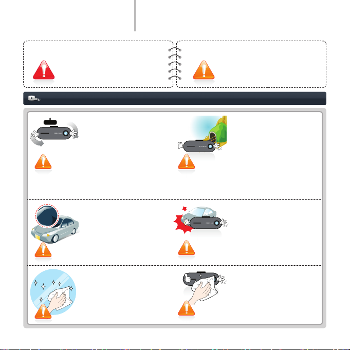
Product
Adjust the angle of a camera
and check the recorded video
after mounting the product:
change of the mounting may
change the angle of the camera.
If the product is mounted on any
improper place, recording may
not be properly performed.
Do not use an excessive tint on
the front window through solar
control lms that disturb clear
video recording.
Some solar control lms may
cause the white-balance used in
video recording to change.
For the best video quality,
keep the front window of your
vehicle clean before starting
recording.
Indicates that violation of the
instruction may cause human
injury or damage of property.
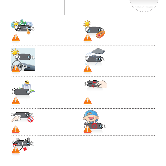
This product records driving video
using a camera. The quality of
video may be degraded in
extreme situations, such as when
the brightness changes rapidly,
when entering or exiting a tunnel,
or when the light is too strong,
for example at noon, or when
there is no light source, for
example at midnight.
When a product has been
damaged or lost due to a big
accident or a break in the
power supply to the product,
an accident video may not be
recorded.
Foreign material (e.g., ngerprints) that stain on the black
box lens may result in a negative impact on the recorded
video. Keep the lens clean.
Safety Instructions
Chapter 01 I General
The best operation temperature
is 0~45°C.
Please keep the temperature in
summer or winter to prevent any
problem.
Please ensure the product is kept
out of direct sunlight and do not
leave the product in the sealed
vehicle.
It may cause failure of the product.
Use THINKWARE-sold articles
correctly.
THINKWARE is not liable for any
product damage or personal injuries
that occur due to accidents or the
incorrect use or operation of this
product.
Do not clean the product using
chemicals or detergent.
Just softly clean it with a cloth.
If the product is used or kept under
0°C or over 45°C, malfunction or
failure of the product may occur.
Please pay attention to the temperature
of the place where the product is
stored.
Do not use the product in a place
where the temperature and/or
humidity is too high.
If the product is made wet by rain or
a beverage-spill, causing irreversible
damage, the user is liable for any
damage caused.
Do not press the buttons with
too much pressure.
It may cause failure of the product.
Keep the product out of reach from
children or pets for their safety.
Otherwise, they may be seriously
injured.
Do not drop the product nor disassemble without any direction of THINKWARE.
Do not press the Reset button with anything sharp.
It may result damage or failure of the product.
www.inavi.com
I 5
Safety Instructions
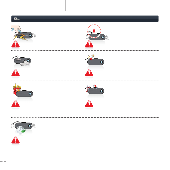
Power
Do not touch the cigar jack cable
power cable with wet hands.
This may result in electrical shock.
Insert the cigar jack cable until
it is stable.
Unstable connection may result
in re.
www.inavi.com
6 I
Do not use any damaged cigar
jack cable.
This may result in re or electric
shock.
Do not place the product or the
cigar jack power cable near to
heating apparatus.
This may result in re or electric
shock.
Do not bend, pull, or press the
cigar jack cable with an excessive
power or anything heavy.
This may result in re or electric
shock.
Do not remodel or cut the cigar
jack cable.
This may result in damage to the
product or vehicle. The user is liable for any damage caused to the
product or vehicle by the failure to
observe the above warning.
If the product is not be used for a long time, please detach the cigar jack cable from
the product.
Otherwise, the vehicle battery may be discharged or re may occur. The user is liable for
any damage caused to the product or vehicle by the failure to observe the above warning.
Safety Instructions
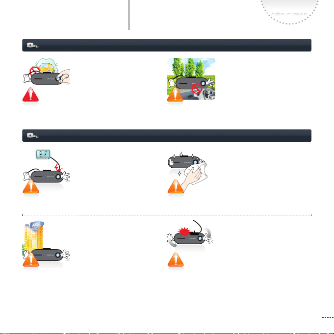
Driving
Do not operate the product
while you are driving.
You may be distracted, resulting
in a car accident.
Product Management and Customer Support
THINKWARE does not guarantee
compatibility with third-party’s
devices or peripherals.
The user is liable for any damage
or failure caused by the unauthorized use of third-party devices or
peripherals.
If any problem is detected in the
product’s operation or such a
possibility exists, contact the
Customer Center.
Otherwise, the problem may
become serious and you cannot
be helped with customer service
successfully.
Chapter 01 I General
Do not install the product in a
location that hinders your driving
or road-visibility.
This may result in an accident.
Be careful that no foreign material
enters the product or cables.
Foreign material in the product may
result in the malfunction or failure of
the product.
Be sure that the camera angle is
correct if the product has been
mounted and used for a long time
or used in a severe-vibrating driving
environment such as on unpaved
roads.
When the positioning of the
product or the camera angle is not
proper, the recording may not be
completed successfully.
www.inavi.com
I 7

Components
Basic Components
Components are subject to change for performance or quality improvement without notice.
You can order new components at iNAVI Shopping Mall (http://mall.inavi.com).
Vehicle Drive Recorder Holder Cigar Jack Cable
Micro SD Memory Card Micro SD Adaptor User Manual
Optional Accessories
AV-OUT Cable Continuous power cable External GPS
www.inavi.com
8 I
Three Cable Holders
(three)
expendables
Part Names
USB
USB
MIC
RESET
micro SD
The images presented here may be dierent from the product. (For the purpose of the improvement
Chapter 01 I General
of the performance of quality of the product, the parts may be changed without any prior notice.)
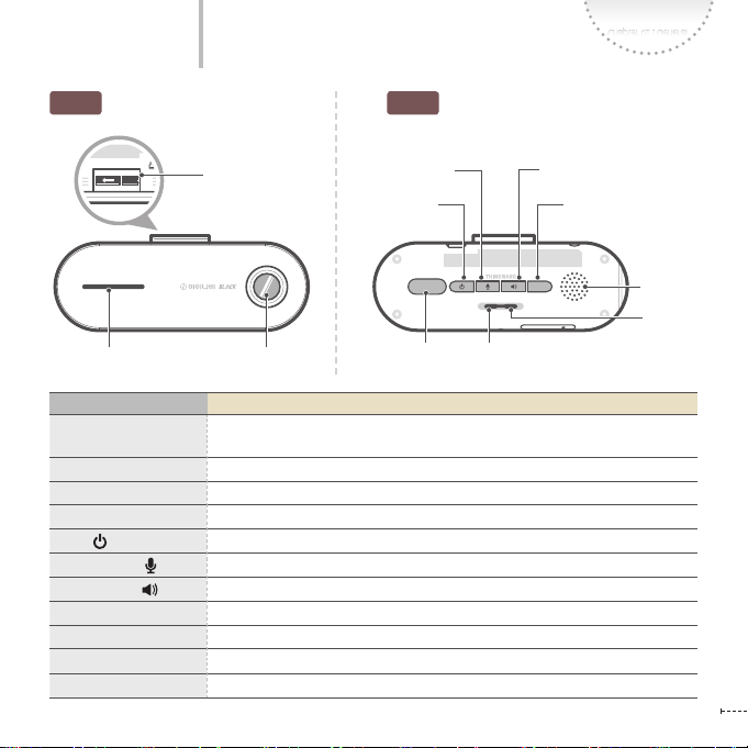
Front
Holder connector
Rear
Voice Recording
Voice Guidance
Power SD memory format
SD FORMAT
GPS
micro SD
Operation Status LED
Security LED
Camera Lens
REC
STATE
REC
(Manual Recording)
Name Function Description
Holder connector
Security LED An aesthetic, security LED moving left and right to act as a warning and prevent theft.
Camera Lens
REC Button
Power Button
Voice Recording button
Voice Guidance Button
SD Memory Format button
Speaker
Operation Status LED
GPS LED
Connects the black box to the holder. (For how to mount the product to the holder,
see page 15.)
Records the front view as seen from the vehicle.
Starts the manual recording
Power ON/OFF (press button for more than 3 seconds)
Voice recording setting/disabled
Voice Guidance setting/disabled
Formats the SD memory (press button for more than 3 seconds)
Alerts as to the operational status of BLACK BOX through its voice-commands and Beep sounds.
Displays the operation status of the product.
Displays the GPS antenna connection status in green.
www.inavi.com
Speaker
GPS LED
I 9
REC
GPS
SD FORMAT
STATE
micro SD
MIC
RESET
REC
micro SD
GPS
SD FORMAT
STATE
micro SD
A/V OUT
GPS
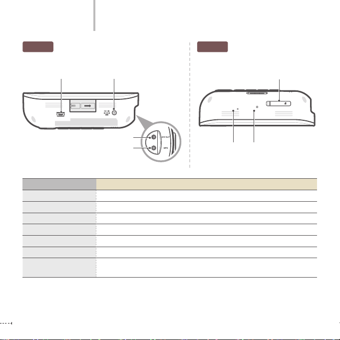
Part Names
BottomTop
USB terminal Power IN Terminal
USB
Name Function Description
USB Terminal
Power IN Terminal
A/V OUT Terminal
GPS Terminal
Micro SD Memory Card Slot
Microphone
RESET
www.inavi.com
10 I
Micro SD Memory Card Slot
RESET
MIC
A/V OUT Terminal
GPS terminal
Microphone RESET
By interworking with iNAVI Navigation, it plays and manages the recorded video.
Connects the power cable.
Outputs recorded video and/or video, which is currently recording to external devices.
Connects the GPS antenna.
Saves the recorded video.
A built-in microphone records sound while recording the video.
Press this to reboot the black box when operation is stopped and the function does
not work.
micro SD

How to Install the Product
How to Insert/Remove Micro SD Memory Card
If the micro SD memory card is inserted
forcibly into the wrong direction, the card
may be damaged and its repair will be
charged for.
Since the memory card is consumable with a limited life, regular inspection or replacement is
required.
For the memory card, it is recommended that you purchase and use our retail product. We shall
hold no liability for problems incurred in connection with the use of our genuine memory card.
To separate the memory card from terminal (product), ensure that the power of terminal is turned
o. Otherwise, it may cause error and/or failure.
It is recommended that you back up the data in a separate storage (PC, etc) besides the memory
card to avoid any loss of data.
Chapter 01 I General
Insert the micro SD memory card into the micro
SD memory card slot according to the arrow
direction showed on the SD memory card slot.
Inserting direction
Removing direction
Rear
.JDSP4%.FNPSZ$BSE.JDSP4%.FNPSZ$BSE
Since it is one-touch type, just press the end
of the micro SD memory card and then the
card will automatically be removed.
www.inavi.com
I 11
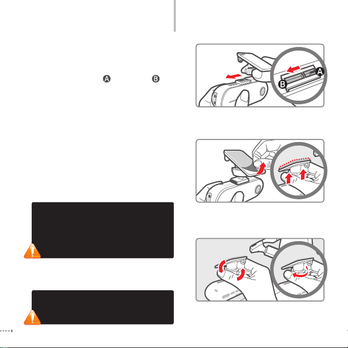
How to Install the Product
By adjusting the grooves on the holder-connector,
1
connect it the black box.
Slide the holder onto the wider groove of the black
box’s holder connector and push it to until it
‘clicks’ and rmly ts in.
Remove a lm from the double-sided tape and
2
attach one side to the holder. Attach the holder
to a location that does not hinder your driving or
outside visibility.
We recommend that you install the black box behind
the rearview mirror. Select a location that allows for easy
button control. Wipe all foreign material and moisture
from the surface to which the double-sided tape will be
attached using a soft and dry cloth.
Checking camera recording direction
1. Using [Black Box Live View] through
interworking with iNAVI navigation
2. Checking the recorded video through the
PC Viewer
Adjust the body to a proper angle and x it by
3
tightening the screw of the holder.
If you do not tighten the screw of the holder,
the video may not be recorded properly due
to the rocking of the body or other causes.
www.inavi.com
12 I
Chapter 01 I General
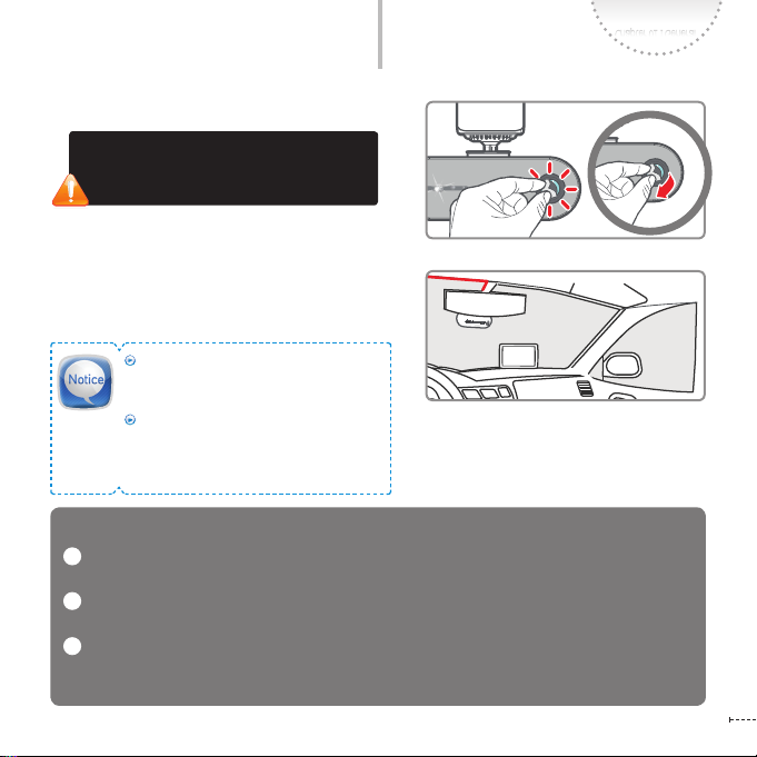
How to Install the Product
Remove the camera lens protection le.
4
If the lm is not removed, the quality of
recorded video will be degraded. Be careful
not to stain the lens with ngerprints.
Connect the power cable (cigar jack cable)
5
and organize the cable using the cable
holders.
For the best video quality, keep the front
window of your vehicle clean before starting recording.
Foreign material (e.g., ngerprints) that
stain on the black box lens may result in
a negative impact on the recorded video.
Keep the lens clean.
Notes for installing the black box
1 A vehicle cigar jack cable is provided along with our black box as a default component. A continu-
ous power cable (optional) is up to the user.
2 We recommend you to let a specialist install and mount our iNAVI black box at our ocial iNAVI
retail shop or agency. (See the iNAVI home page for the ocial retail shops and agencies.)
3 If you need to mount or remove your black box, you can get our help at our ocial iNAVI retail shop
only when you have installed it at the ocial iNAVI retail shop. We do not provide any support for
installation or mounting of the black box.
www.inavi.com
I 13
www.inavi.com
www.inavi.com

Chapter 02 I Basic Information
Basic Operation
Connecting the Power 16
Power ON/OFF 16
Connecting the External GPS Antenna (Optional)
Connecting the AV OUT (Optional) 18
Recording while Driving 19
Auto parking mode setting (default setting) 20
Manual parking mode setting 20
Recording while parking 21
Recording le 22
Manual Recording 23
Setting Voice Functions 24
Setting Security LED 25
Playing mode 26
Formatting Micro SD Card 27
Upgrading the Program 27
Button Functions 28
Operation Status LED and Voice (BEEP) Operation Mode
17
28
Basic Operation
SD FORMAT
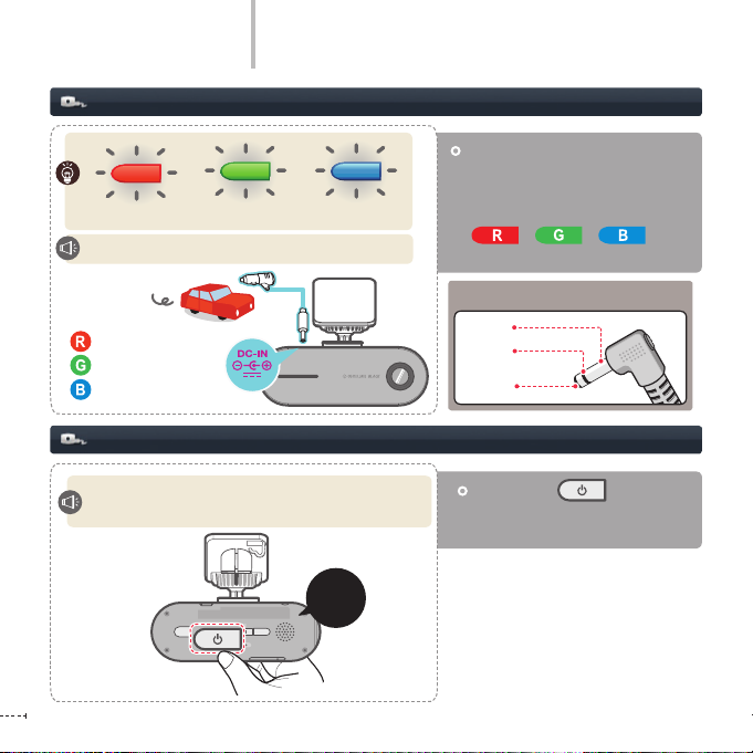
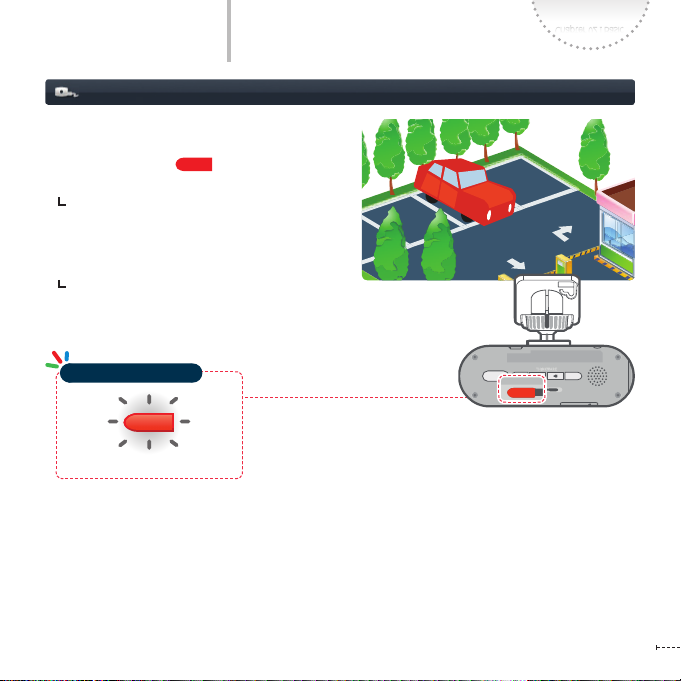
Connecting the Power
+
Three colors blinking
+
Please have a safe and enjoyable drive today.
Car power cable
(cigar jack cable)
: Red
: Green
: Blue
Power ON/OFF
POWER ON : Please have a safe and enjoyable drive today!
POWER OFF: Shut down the system.
SD FORMAT
GPS
STATE
micro SD
www.inavi.com
16 I
REC
Long
(more than
3 seconds)
Install the product and then turn
ON the power of the product or
start up the product. The operation
status LEDs blink in three colors
( / / / ) with
voice guidance.
Power 3-pole jack polarity
GND
ACC
B+
Press Power ( ) button for
more than 3 seconds to turn the
power ON/OFF.

Basic Operation
REC
GPS
SD FORMAT
STATE
micro SD
GPS
Connecting the External GPS Antenna (Optional)
Chapter 02 I Basic
The GPS has been connected.
GPS is aected by weather condition, satellite condition and geographical features.
The reception condition may be bad due to weather condition, satellite condition and geographical
features.
If the front window is tinted or coated with metal components, GPS may not be able to receive
signal properly.
Carefully install GPS in consideration of conditions above.
If a device, which emits electromagnetic waves causing GPS signal interference, GPS may not be able
to receive signal properly.
If other GPS device is used together in the car, the signal to GPS may be interrupted and cause reception
problem.
GPS LED
Connecting the external GPS antenna
Make sure that you turn o the
power before connecting the
external GPS terminal for receiving
GPS info.
Connect the external GPS terminal
and turn on the power. The GPS
operates with voice guidance.
Simultaneously press both of
button and Voice Recording
button to reset GPS
Do not use the external GPS
antenna provided by the third
party. Otherwise, the external
GPS terminal may be damaged
or GPS reception may not work
normally.
reception.
www.inavi.com
I 17
REC
GPS
SD FORMAT
STATE
micro SD
A/V OUT
Basic Operation
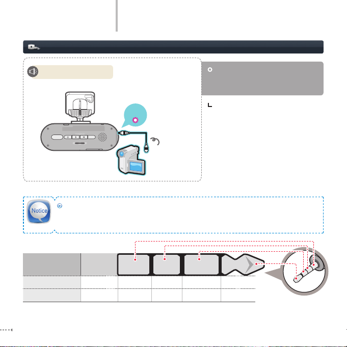
Connecting the AV OUT (Optional)
Start video playback.
www.inavi.com
18 I
AV OUT
Connect the AV OUT cable to the
AV OUT terminal to output the recorded video to an external device.
With AV OUT connection, view real-time
video on external device. (see 29 page,
Playing Mode)
Displaying recorded
video
Please use the standard AV cable recommended by THINKWARE.
If any unsupported AV cable is connected, this may result in damage to the product, for which
THINKWARE does not accept any liability.
Item Plug
GPS
ø
2.5
ø
2.5
-- GND VIDEO --
RX GND TX VCC
REC
GPS
SD FORMAT
STATE
micro SD
REC
GPS
SD FORMAT
STATE
micro SD
REC
GPS
SD FORMAT
STATE
micro SD
GPS
SD FORM AT
micro SD
GPS
SD FORM AT
REC
GPS
SD FORMAT
STATE
micro SD
REC
GPS
SD FORMAT
STATE
micro SD
GPS
SD FORM AT
GPS
SD FORM AT
micro SD
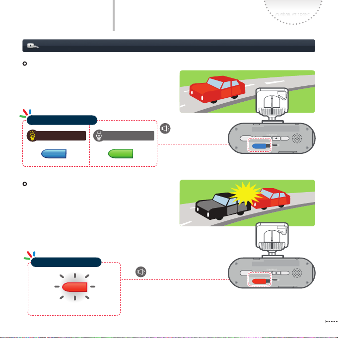
Basic Operation
All videos are recorded in interval of one-minute
Recording while Driving
Continuous Recording
and saved in Continuous recording folder.
Chapter 02 I Basic
Operation Status LED
Voice Recording ON Voice Recording OFF
Event Recording
When the impact of which strength exceeds the
user-specied strength, the black box records
scenes for 20 seconds; from 10 seconds before the
event (impact) has occurred to 10 seconds after
that and automatically saves the video in the Event
Recording folder.
Operation Status LED
Blinking
Starts the continuous
recording
(Ring) the buzzer sounds
www.inavi.com
I 19

REC
GPS
SD FORMAT
STATE
micro SD
REC
GPS
SD FORMAT
STATE
micro SD
REC
SD FORMAT
REC
GPS
SD FORMAT
STATE
micro SD
REC
GPS
SD FORMAT
STATE
micro SD
GPS
SD FORM AT
GPS
SD FORM AT
micro SD
GPS
SD FORM AT
Basic Operation
Auto parking mode setting (default setting)
+
Cross blinking
Starts parking recording.
Cross
light on
Manual parking mode setting
When the vehicle power is turned o, the
mode is automatically changed to the
ParkingMode with voice guidance.
You need the PC Viewer and Live View
conguration. (The default setting is
the Auto Parking Mode)
To change to Auto Parking mode is available,
you should use our retail continuous power
cable. (If the cable is not our retail continuous
power cable, the product may malfunction.)
It takes about 30 seconds to switch to the Auto
Parking Mode, however, the mode may not be
switched to the Auto Parking Mode to prevent
discharge of the battery.
20 I
Cross blinking
Starts parking recording.
Long
(more than
3 seconds)
www.inavi.com
+
Press the REC ( ) button (for more
than 3 seconds) to change to the Parking
Mode with voice guidance.
Basic Operation
REC
GPS
SD FORMAT
STATE
micro SD
REC
GPS
SD FORMAT
STATE
micro SD
REC
GPS
SD FORMAT
STATE
micro SD
GPS
SD FORM AT
micro SD
GPS
SD FORM AT
When any motion or impact or motion is detected
within the recording scope of the black box, the
Recording while parking
operation status LED ( ) lights on in red.
Event detection recording : Records scenes
for 20 seconds, from 10 seconds before the
event has been detected to 10 seconds after
and saves in the Event Recording Folder.
Motion detection recording : Records scenes
for 20 seconds, from 10 seconds before the
motion has been detected to 10 seconds after
and saves in the Motion recording folder.
Operation Status LED
Blinking
Chapter 02 I Basic
www.inavi.com
I 21

Basic Operation
Recording le
The recording folder created in the Micro SD card
is based on date/time in the order of time. In the
created folder, les in the unit of date/time are
created.
The recording le is created based on the
recording start time.
Year
Up to 100 recording les can be created in one
date/time-based folder.
If the le size exceeds the micro SD card capacity,
the oldest le or folder is deleted sequentially
and creates new date/time folder and recording
le.
www.inavi.com
22 I
Month
Date
Minute
Hour
Second

REC
GPS
SD FORMAT
STATE
micro SD
REC
GPS
SD FORMAT
STATE
micro SD
REC
SD FORMAT
GPS
SD FORM AT
micro SD
GPS
SD FORM AT
Basic Operation
Manual Recording
Instead of only recording accident videos, you can record what you want to keep such as beautiful scenery or
places as well as any scenes which must not be deleted.
Manual Recording
In Continuous recording mode, the pressing of
the REC ( ) button shortly even when
no accident has occurred will save scenes for 20
seconds from 10 seconds before the button has
been pressed to 10 seconds after in the Manual
Recording folder.
Operation Status LED
Start the manual
recording
Chapter 02 I Basic
Lights on
Shortly
www.inavi.com
I 23

Basic Operation
REC
GPS
SD FORMAT
STATE
micro SD
REC
GPS
SD FORMAT
STATE
micro SD
REC
GPS
SD FORMAT
STATE
micro SD
REC
GPS
SD FORMAT
STATE
micro SD
SD FORMAT
SD FORMAT
Setting Voice Functions
Voice Recording ON/OFF
Press the Voice Recording ( ) button to turn ON/OFF voice
recording with beep sound.
Starts/stops voice recording.
Voice guidance ON/OFF
Press the Voice Guidance ( ) button to turn ON/OFF voice
guidance with beep sound.
Beep – Setting values have been changed. /
Beep Beep – Setting values have been changed.
In no event shall this product be used dierently from its original purpose, nor arbitrarily changed.
In accordance with the ‘Privacy Protection Laws and relevant laws,’ if any others’ voice is recorded in
this product using the recording function, the user shall accept liability for its recording.
www.inavi.com
24 I

Basic Operation
REC
GPS
SD FORMAT
STATE
micro SD
REC
GPS
SD FORMAT
STATE
micro SD
SD FORMAT
Setting Security LED
Press the Voice guidance ( ) button for a few seconds to turn ON/OFF
the Security LED.
Chapter 02 I Basic
Security LED ON Security LED OFF
Start/stop Security
LED.
Setting the Mode
In Parking Mode, you can set Security LED ON/OFF mode on the PC Viewer.
- Mode 1: Left. Right scroll
- Mode 2: Blinking (0.5 second interval)
- Mode 3
Event detection recording
Motion detection recording
- Mode 4: Turn o (Not used)
www.inavi.com
I 25

Basic Operation
REC
SD FORMAT
Playing Mode
Voice Recording ( )
Voice guidance ( )
SD Memory Format
www.inavi.com
26 I
Start video playback.
After power o, connect power while
pressing the REC( ) button and
Playing Mode starts.
REC
Button
Power ( )
SD FORMAT
GPS
STATE
micro SD
Connect the external devices to the black box using AV-OUT cable.
It is recommended to use the standard AV-OUT cable guaranteed by our company.
Function
List of recording les and setting mode Video Playback Mode
Select File/Menu Play/Pause
Move to Upper File/Menu Fast Play to Forward
Move to Lower File / Menu Fast Play to Backward
Exit
Stop the video and go to the list of the
recording file

Chapter 02 I Basic
REC
GPS
SD FORMAT
STATE
micro SD
REC
GPS
SD FORMAT
STATE
micro SD
REC
GPS
SD FORMAT
STATE
micro SD
GPS
SD FORM AT
micro SD
GPS
SD FORM AT
REC
GPS
SD FORMAT
STATE
micro SD
REC
GPS
SD FORMAT
STATE
micro SD
SD FORMAT
Basic Operation
- Press the SD Memory Format ( ) button for a few seconds and then the operation status LED
Formatting Micro SD Card
blinks in green and the Micro SD card can be formatted.
Operation Status LED
Formatting the micro
Blinking
Press the SD Memory Format button shortly and photo shooting is started with a ‘click’ sound.
- The photo is saved in the Photo folder.
SD memory card.
Program Upgrade
When an upgrade le exists in the micro SD card, an upgrade can be carried out.
After completing the upgrade, the program automatically restarts.
Operation Status LED
Start upgrade.
Blinking
www.inavi.com
I 27

Basic Operation
Button Operation
Button Pressed for less than 3 seconds Pressed for more than 3 seconds
Voice Recording button
Voice Guidance Button
SD Memory Format Button
Button
Operation Status LED and Voice (BEEP) Operation Mode
Operation Mode
voice recording setting/disabled
voice guidance setting/disabled Securit y LED ON/OFF
Photo Shooting Formats the SD memory
Manual Recording Sets/Ends Parking Mode
Voice Recording (ON) Voice Recording (OFF)
LED
Continuous Recording
www.inavi.com
28 I
BOOTING
Voice Guidance
Voice Guidance
Even Recording
Voice Guidance
+ +
Blinking in three colors
Please have a safe and enjoyable drive today.
Blinking in Blue Blink ing in Green
Starts the continuous recording.
Blinking in Red
(Ring) the buzzer sounds

Basic Operation
Operation Status LED and Voice (BEEP) Operation Mode
Operation Mode
Voice Recording (ON) Voice Recording (OFF)
Chapter 02 I Basic
LED
Parking Recording
(Waiting)
Voice Guidance
Parking Recording
(during recording)
Manual Recording
Voice Guidance
SD Card Format
Voice Guidance
+
Cross blinking
Setting Start Parking recording.
Releasing End Parking recording.
Event Recording Motion Recording
Blinking in Red
Blinking in Red
Setting Start Manual recording.
Releasing End Manual recording.
Blinking in Green
Formatting the micro SD memory card.
www.inavi.com
I 29

Basic Operation
Operation Status LED and Voice (BEEP) Operation Mode
Operation Mode LED
Firmware Upgrade
Voice Guidance
Blinking in Red
Start upgrade.
Abnormal operation
(malfunction, bad recording)
Voice Guidance
When the space for Continuous Recording is insucient, the oldest video les are automatically
deleted with new les then being saved. However, in this case, any video les saved in the Event
Folder will not be deleted.
While there are only the video les in Event Folder and the space is insucient, the oldest Event
video les will be automatically deleted. Therefore, please save important video les to the SD
card of the Navigation device, the hard disk of a PC, or any other storage-devices for safe backup.
(However, if overwrite by recording video is disabled, newly created event videos will not be
stored in the case of insucient space in event folder)
www.inavi.com
30 I
+ +
Blinking in Red / Blue / Green
Supports voice guidance according to the situation.
Ex: Insufficient space in the Event Recording Folder.
(Video recording is unavailable sue to lack of memory space)

Chapter 03 I Menu
PC Viewer
PC Viewer
Installing a Program 33
Screen Conguration 34
Getting Started 36
View the Recording Folder 38
View Full Screen 39
View Map 40
Self-diagnosis 41
Black Box Setting > Video 42
Black Box Setting > Audio 44
Black Box Setting > Parking Mode 45
Black Box Setting > Additional Functions 49
Black Box Setting > Acceleration Gauge 57
Black Box Setting > Accident Report 58
Screen Capture 59
Version Info and Firmware Download 60

PC Viewer

PC Viewer
Installing a Program
You can view the video le recorded by the black box through the PC Viewer.
To play the saved video le on the PC, you must download the program from the THINKWARE home page.
www.inavi.com > Upgrade > Black Box Upgrade
1
and then download the setup le.
Double-click the downloaded le on the Windows
2
Explorer.
First, the dshow codec is installed and then the
3
integrated PC Viewer program is installed.
- After completing installation, click the Complete
button to exit the installation window.
4
Check whether the iNaviPlayer shortcut has been
installed on the Desktop or not.
Recommended Specications for PC Viewer
Operating System (OS): Windows XP(32bit), Windows
Vista(32bit), Window7(32/64bit)
Pentium 4 / 2.8Ghz or higher / RAM 1G or higher
Disk Space: HDD 4GB / DirectX 9.0 or later
Microsoft Internet Explorer 7.0 or later
Chapter 03 I Menu
www.inavi.com
I 33

PC Viewer
Screen Conguration
Playback
Screen
File Infor-
mation
Adjust Playback
www.inavi.com
34 I
Configuration Accident Report
Acceleration
Self-diagnosis
Playback Progress Status Bar Continuous Recording:
Speed
Gauge
Current Playtime/ Total Playtime
Update the firmware and view the version info
Screen
Capture
Adjust Playback VolumeAdjust Screen Brightness
Access the iNAVI Web site.
Hide/Full Screen/End
View Map
Immediately
shows the recording location and
point (only when
the Internet is
connected)
Zoom in Map
Manual Recording
Motion Recording
Event Recording
Play List

PC Viewer
Screen Conguration
Chapter 03 I Menu
Play the Previous File Plays the previous file of
the one which is playing.
Play the file / Resume
Play the recorded file / Resume the file play
Stop Stop play
Play the Next File Plays the file next to the
one which is playing.
Move to Previous Goes backward by one
second while playing a file
Move to Next Goes forward by one second
while playing a file
Quick Play
Quickly plays the file
Open a Drive Opens the removable storage
device where the recording files are saved
Save the recording file Saves the recording file
being played to the PC
Adjust Playback Speed Adjusts the playback
speed by controlling the scroll bar left or right
(by controlling the scroll bar)
Brightness Adjusts the brightness by control-
ling the scroll bar left or right
(by controlling the scroll bar)
Volume Adjusts the volume by controlling the
scroll bar left or right
(by controlling the scroll bar)
www.inavi.com
I 35

PC Viewer
Executing a PC Viewer
www.inavi.com
36 I
The micro SD memory card reader is an additional product. You can buy it through the
iNAVI homepage.
Insert the micro SD memory card into the micro SD
Front
1
card reader by placing it in with the top of the card
upwards and connect to the PC.
Please make sure that you insert the micro SD card
reader to the reader in the correct direction.
Front
Rear
Micro SD Memory Card
2
Double-
click
If a micro SD card has been inserted in the product but has never
been used, the drive cannot be opened. In this case, insert the
micro SD card in the product and record at least one le.
Removing Micro SD Card
Press the red button
of the micro SD card
reader in the direction
as shown in the gure.
The micro SD memory card is then removed.
Execute the iNaviPlayer icon on the Desktop to
execute the PC Viewer program.
The PC Viewer program screen appears.

PC Viewer
Executing a PC Viewer
Setup le in Micro SD memory card
Chapter 03 I Menu
Open a Drive ( )
3
Select the removable storage device of the micro SD
card connected to the PC and select OK.
Setup le in Micro SD memory card
Click Open ( ) :
When the model (number) appears on the screen
after reading Setup le, select the setting (conguration) correspond to that model (number)
Click Setting icon :
The setting (conguration) screen correspond to
the model (number) appears.
No Setup le in Micro SD memory card
Click Open ( ) / Setting icon :
When the window in which you can input the model
(number) on the screen and the model number appears on PC Viewer, select the setting (conguration)
correspond to
Double-
click
or
that model.
4
The recording folders and les saved in the selected drive
are listed up in the File List.
In the File List, select a desired le, and then double-click
it on the list or click the Play icon to play the le.
www.inavi.com
I 37

PC Viewer
View the Recording Folder
You can view the list of recording les
by selecting each recording folder
(Continuous Recording, Event Recording, Manual Recording, and Motion
Recording).
Continuous Recording List Screen Event Recording List Screen
www.inavi.com
38 I

PC Viewer
View Full Screen
If the resolution of the monitor is higher than the resolution of the original video (1280x720) :
the displayed resolution is same with the resolution of the original video.
If the resolution of the monitor is lower than the resolution of the original video (1280x720) :
the displayed resolution is adjusted to the resolution of the monitor.
Chapter 03 I Menu
Click the Full Screen ( ) icon on the
top of the PC Viewer to enlarge the play
screen to the full screen of the monitor.
On the full screen, click the Zoom out
icon on the top of the PC Viewer to
change the screen to the standard
screen display ratio.
www.inavi.com
I 39

PC Viewer
View Map
Click the Zoom-in Map icon on the
upper right hand corner of PC Viewer to
enlarge the map to the full screen.
On the full screen, click the Zoomout Map to switch over the screen to
the front view.
www.inavi.com
40 I

PC Viewer
Self-diagnosis
Chapter 03 I Menu
For A/S he self-diagnosis of the black
box is carried out.
Menu includes Examination Date/
Product Name/Resolution/Quality Setting/
Brightness/Contrast/Sharpness/
Voice Recording/Voice Comment/
Voice Comment Volume/Camera Location/
Acceleration Sensor Sensitivity/
Memory Partition/Event File Overwriting/
Manual Recorded Video Overwriting/
Recorded Motion File Overwriting.
www.inavi.com
I 41

PC Viewer
Black Box Setting > Video - 1
1
2
Quality
1
The resolution of iNAVI BLACK Clair2 is
set to the following by default.
VGA(640X480) (not available)
HD(1280X720) (default value)
FHD(1920X1080) (not available)
Frames
2
You can set the recording frame of the
black box to three levels:
Variable: Min. 15 fps ~
Max. 30 fps
Fixed (15f): 15 fps (default value)
Fixed (30f): 30 fps
www.inavi.com
42 I

PC Viewer
Black Box Setting > Video - 2
3
4
Chapter 03 I Menu
Video Quality
3
Displays the time and number of the
recording les by Continuous/Event/
Manual/Parking recording to the Quality
setting.
- : Continuous Area
- : Event Area
: Manual Area
-
-
: Motion Area
The value varies according to the
memory partition setting set in
Conguration.
Adjustment
4
Adjust the screen setting values for
recording.
- Brightness: Adjust the brightness
level of the screen. (-3 ~ +3)
- Contrast: Adjust the contrast of the
screen. (-3 ~ +3)
- Sharpness: Adjust the sharpness of
the screen. (-3 ~ +3)
www.inavi.com
I 43

PC Viewer
Black Box Setting > Audio
1
Voice Recording
1
Turns on or o the voice recording of the
black box.
Use (default setting)
Not Use:
www.inavi.com
44 I
2
Voice comment
2
Turn on/o the voice comment of the
black box.
Use (default setting)
Not Use:

PC Viewer
Black Box Setting > Parking Mode - 1
1
2
3
Tips for Sensitivity Setting
For the high-class sedan of which vibration
level is low, set the level high. For trucks and
RVs of which vibration level is high, set the
level low.
Chapter 03 I Menu
Recording Quality
1
Sets the recording quality of a video for the
Parking recording.
- Recording time and the number of
events saved diers according to the
memory partition setting.
How to Detect Events
2
Sets the method of Event/Motion detec-
tion recording to be saved in the Event
Folder during the parking recording.
Sensitivity Setting for Parking
3
Mode
Adjusts the sensitivity of event/motion.
(Low ( ) ( ) High)
Event Sensitivity: Up to 10 levels of
event sensitivity can be set. (Default 7
levels)
Motion Sensitivity: Up to 3 levels of
motion sensitivity can be set.
www.inavi.com
I 45

PC Viewer
Black Box Setting > Parking Mode - 2
4
5
Timer Setting for Parking Recording
4
When the parking recording is made
using the continuous power of the
vehicle, the parking recording is ended
after the specied time is expired in
order to prevent battery discharge.
- Range: 1 hour ~ 48 hours (8 levels)
Battery Voltage Setting
5
When the parking recording is made
using the continuous power of the
vehicle, the black box power is blocked
if the voltage is lower than the specied voltage in order to prevent battery
discharge.
Vehicle voltage 12V
- Range of voltage for ending the
recording:
11.7V ~ 12.4V (changed by 0.1V unit)
Vehicle voltage 24V
- Range of voltage for ending the
recording:
23.4V ~ 24.8V (changed by 0.2V unit)
www.inavi.com
46 I

PC Viewer
Black Box Setting > Parking Mode - 3
Notes for Setting Parking Mode (based on 12V of
vehicle battery)
When it takes too much time to change the mode to
Auto Parking mode while driving, or while parking, raise
the voltage for changing to Parking mode.
Setting the range of voltage and time for ending
the recording (based on 12V of vehicle battery)
When recording time becomes too short after changing
the mode to Auto Parking mode, lower the voltage for
ending the recording. (However, if the range of voltage
for ending the recording is set to the too low value, the
vehicle battery may be discharged so please be careful.)
When the voltage is lower than the setting value of volt-
age for ending the recording while setting the recording
ending time, the function to set the voltage for ending
the recording starts rst.
Chapter 03 I Menu
Range of voltage for parking mode:
Min. 12.4V
Changing the mode
to Parking mode
while driving
~
Max. 13.1V
When it takes too much time
to change the mode to Auto
Parking mode while driving
Range of voltage for ending recording
Min. 11.7V
Too long parking
recording time
(the vehicle battery
may be discharged)
~
Max. 12.4V
Too short parking
recording time
(the vehicle battery
discharge will be
prevented)
Functions of auto parking mode and blocking
voltage for ending recording end are available
when our retail continuous power cable is used.
If the product malfunctions even when you
changed the setting values, please check the
terminal and the vehicle battery and if required,
charge the battery.
Set the auto parking mode switch level and the
ending recording level according to the battery
status and usage time before using it.
To adjust the setting values to appropriate
values, change the values by one level for
avoiding malfunctions.
The product may be malfunctioned when you
use other cables but our retail continuous
power cable.
www.inavi.com
I 47

PC Viewer
Black Box Setting > Parking Mode - 4
6
Security LED
Setting Security LED
6
You can set movement of the security
LED to three types:
Mode 1 (Left/Right scroll):
The LED moves left and right.
(default setting)
Mode 2 (Blinking): All LEDs blink at
the interval of 0.5 second.
Mode 3 (Auto):
The Security LED operates dierently
according to the recording mode in
use (Continuous/Event/Manual).
-
Continuous Recording: Left-right Fade
- Event Recording:
Center fade (Fade Out)
- Parking (motion) waiting: Left-right
Fade
- Parking (motion) recording:
Center fade (Fade In)
- Manual Recording: Center fade (Fade
Out)
Mode 4 (Not Used):
The Security LED is turned o.
www.inavi.com
48 I

PC Viewer
Black Box Setting > Additional Functions - 1
System Time
1
You can set the date and time of the
product.
1
Modify the date and time by clicking the Up and Down arrows.
Directly modify the date and time by placing the mouser cursor on the Date/Time.
- To modify the time and save it, rst unlock
the settings by clicking the checkbox
on the right side.
- The time set in the PC is displayed. You can
modify the time by clicking each number.
- After modifying the date and time, click
the Set Device Time button to save the
changes.
- After inserting the saved micro SD card
to the product, turn the power on; the
changed date and time is applied for the
product.
To save the modied date and time, rst unlock the
settings by clicking the lock icon.
Chapter 03 I Menu
The date and time is saved as
‘date_Time.cfg’ in the ‘Setting’
folder of the micro SD folder.
www.inavi.com
I 49

PC Viewer
Black Box Setting > Additional Functions - 2
2
3
Camera location (position)
2
(reversal display)
Install the black box on the glass or on
the dashboard to prevent the display
being upside down.
Acceleration Sensor Sensitivity
3
Adjust the sensitivity of the acceleration
sensor of the black box on a scale of 0 to
10.
(Insensitive ( ) ( ) Sensitive)
www.inavi.com
50 I

PC Viewer
Black Box Setting > Additional Functions - 3
4
The Continuous recording les will occupy the entire capacity of the memory excluding the
minimum recording memory size when there is no Event/Motion/Manual recording le.
The size of a recording le may be dierent by 30 ~ 40MB from the others.
When the memory partition setting is changed, the “Format the Memory” window appears.
The changes will be applied after formatting the memory.
Chapter 03 I Menu
Memory partition
4
In Conguration, you can set the capacity
ratio of Continuous/Event/Manual/Motion recording by each memory (A/B/C).
A Type (Recommended):
Continuous Recording-centered
B Type: Event/Manual Recording-
centered (using double capacity of
A type)
C Type: Event/Manual Recording-
centered (using 4 times of capacity
of A type)
www.inavi.com
I 51

PC Viewer
Black Box Setting > Additional Functions - 4
Setting Value 8GB 16GB 32GB
Type A
[Continuous
Recording-centered]
Event Recording:
400MB (about 9 minutes)
Motion Recording:
800MB (about 18 minutes)
Manual Recording:
250MB (about 6 minutes)
Event Recording:
800MB (about 18 minutes)
Motion Recording:
1600MB (about 36 minutes)
Manual Recording:
250MB (about 6 minutes)
Event Recording:
1600MB (about 36 minutes)
Motion Recording:
3200MB (about 72 minutes)
Manual Recording:
250MB (about 6 minutes)
Type B
[Event/Manual
Recording centered]
(using double-capacity
of Type A)
Type C
[Event/Manual
Recording centered
(using 4 times of
capacity of Type A)
www.inavi.com
52 I
Event Recording:
800MB (about 18 minutes)
Motion Recording:
1600MB (about 36 minutes)
Manual Recording:
250MB (about 6 minutes)
Event Recording:
1600MB (about 36 minutes)
Motion Recording:
3200MB (about 72 minutes)
Manual Recording:
250MB (about 6 minutes)
Actual capacity may dier from the capacity stated above depending on memory type setting.
Event Recording:
1600MB (about 36 minutes)
Motion Recording:
3200MB (about 72 minutes)
Manual Recording:
250MB (about 6 minutes)
Event Recording:
3200MB (about 72 minutes)
Motion Recording:
6400MB (about 144 minutes)
Manual Recording:
250MB (about 6 minutes)
Event Recording:
3200MB (about 72 minutes)
Motion Recording:
6400MB (about 144 minutes)
Manual Recording:
250MB (about 6 minutes)
Event Recording:
6400MB (about 144 minutes)
Motion Recording:
12800MB (about 288 minutes)
Manual Recording:
250MB (about 6 minutes)

PC Viewer
Black Box Setting > Additional Functions - 5
5
Chapter 03 I Menu
5 Setting Overwrite by Recording
Video
Determines whether or not to delete
the oldest le when the Event/Manual/
Motion recording memories of the
black box are full.
www.inavi.com
I 53

PC Viewer
Black Box Setting > Additional Functions - 6
Memory Format
6
Format the micro SD card where the
recording les are saved.
Click the Memory Format button and a
memory format window appears.
Select each format option in the format
window and click the Start button to
execute format.
www.inavi.com
54 I
6
We recommend you to back up data
before formatting the memory.
If you format the memory, the saved
data is deleted and any deleted data
cannot be then restored.
The format conguration window may vary
according to the OS installed in the user’s PC.

PC Viewer
Black Box Setting > Additional Functions - 7
8
Chapter 03 I Menu
Apply the settings
7
After completing the settings, click the
Save button to save the settings to the
micro SD card.
The saved conguration le is created
as the setup.cfg le in the Setting
folder of the micro SD card.
Insert the micro SD card to the
product and turn on the power.
The product boots up with the
settings being simultaneously
applied to the product.
If you forcibly delete the setup.
cfg le, you cannot use it on the PC
Viewer. In this case, insert the micro
SD card to the product and operate
the product. Then the setup.cfg le
is created as a default setting and it
can be used on the PC Viewer again.
www.inavi.com
I 55

PC Viewer
Black Box Setting > Additional Functions - 8
9
Resetting the Conguration
8
To apply the initial setting values, not
the user-specied values, click the Reset
Values button on the right bottom side
of the screen.
The setting values are saved in the micro
SD card. Therefore, insert the micro SD
card to the product and turn on the
power. The product boots and the
settings are simultaneously applied to
the product.
www.inavi.com
56 I

PC Viewer
Black Box Setting > Acceleration Gauge
Chapter 03 I Menu
Display left/right, rotation/vibration/
impact and other information using the
acceleration of gravity on 3 axes (X, Y, Z)
based on the data acquired by the sensor, which recognizes the acceleration
of gravity applied on the car.
- Indicate the name of le you are
currently playing
- Display the le size and the time of
recording
- Display the value on 3 axes (X, Y, Z) of
speed and acceleration sensor
www.inavi.com
I 57

PC Viewer
Black Box Setting > Accident Report
When you click Accident Report while
playing the video, the video immediately stops and the time, GPS data and
speed (appeared on the screen) are
displayed. (Printable)
Save: the data is saved as [inaviBlack_
Accident Report.jpb] on the
desktop.
The number of characters of a
le name is limited. So you have
to make the le name briey.
Otherwise, the le name cannot be
assigned to the saved .jpg le.
www.inavi.com
58 I

PC Viewer
Screen Capture
The captured screen is saved as a
JPEG image le.
Chapter 03 I Menu
Capture the images of the recorded
video being playing now.
Click the Capture icon on the top of
the PC Viewer to capture the screen
currently being played.
When the video screen is captured,
a Windows Explorer screen appears
to search the folder where the
captured image will be saved as
JPEG image le, allowing for
entering the le name.
On the explorer, type the le name
and folder name and click the Save
button to complete screen capture.
www.inavi.com
I 59

PC Viewer
Version Info and Firmware Download
Click the Firmware button on the top of
the PC Viewer and an Update Firmware
Information window appears.
Viewer Version
On the Version Info on the Update
Firmware window, you can view the
version information on the PC Viewer
and rmware being used.
Firmware Update
①
Click the Go to Update Page button to
move to the upgrade page. (login is
required)
②
Selec t the latest rmware on the page
and click the Firmware Download
button.
③
Move the ve les downloaded in the PC
to the top folder of the micro SD card of
the black box.
④
Inser t the micro SD card where the
rmware is saved into the product
and turn on the power. Then upgrade
automatically starts.
www.inavi.com
60 I

Chapter 04 I Others
Product Specications 62
Customer Center
Product Registration 64
Before requesting A/S... 64
Q&A and Request A/S 65
Product Warranty 68

Product Specifications
For the purpose of the improvement of the performance of quality of
the product, the parts may be changed without any prior notice.
Item Specications Remarks
Model iNAVI BLACK Clair2
Dimensions/Weight 110 x 38 x 33.3mm / 73.7g
Capacity Micro SD Memory Card 8/16/32GB
Continuous Recording Recording in the unit of one minute
Event Recording
Manual Recording
Recording Type
General Recording Quality Total 3 Levels
Camera 2.0M Pixels, 1/3.2" CMOS More than about 2 megapixel
Angle of View About 140° (based on the opposite angle)
Video
Frames
Audio PCM (Pulse code modulation)
Acceleration Sensor
GPS Suppor ting external GPS port (2.Ø)
Input Power DC 12/24V DC 12V is superior when both of two are supplied
Current consumption 3.1W(Max) Black box power consumption
Parking Recording (Parking Mode)
Photo
Voice Recording (the initial mode is OFF)
HD (1280X720/H.264/Extension MP4)
HD-level video 1280 x 720 1Ch. 30F(MAX)
3-axis acceleration sensor (3D, ±4G)
10 seconds before and after an event occurs
(total 20 seconds)
Additional device or installation is required for
providing continuous power
*.JPG
Voice Recording button (within 3 seconds) /
available to set voice recording ON/OFF
Recording time diers according to the partition
setting
10 levels of sensitivities
Purchase an external GPS compatible with iNAVI
Black Clair2
www.inavi.com
62 I

Product Specifications
Item Specications Remarks
Auxiliary power source super-capacity
Security LED
Alarm LED
Alarm Built-in speaker Voice (BEEP) guide
External Output NTSC
Operation Temperature/
Storage Temperature
Interface One AV-OUT port (2.5Ø)
Panorama White LED
LED displaying status of connection to
Operation Status LED and GPS
-10~60°C
Plays the video in real time or the recording video /
Conguration function
Chapter 04 I Other
www.inavi.com
I 63

Customer Center
Thank you for purchasing THINKWARE iNAVI product.
Product Registration
Press the Register Product menu on the right
upper side of the home page.
If you are new to this Web site, please join us rst.
You can view the list of product registration in the
site only when you are logged into the site.
The serial number required for registering your
product is on the side of the product or the
Product Warranty of the user manual.
After completing your product
registration, you can download the
user manual, rmware, PC Viewer, etc.
Loss of the serial number is equivalent to loss of the product.
If you lose the serial number, it cannot be re-issued and no iNAVI member service such as upgrade can
be provided.
Before requesting A/S...
Important data saved in the product, including storage data, should be regularly backed up
(or saved to another device). In some cases, you may inevitably delete data from the built-in
storage part. In this case, all data in the product may be deleted for A/S. Please note that you
MUST directly back up any important data before requesting A/S.
All products for which A/S is requested and are received by iNAVI Customer Center will be
considered as though they have been backed up by respective users and thus any additional backup will not be
carried out. Therefore, please keep in mind that THINKWARE is not liable for such deletions of data carried out in the
process of A/S.
www.inavi.com
64 I

Chapter 04 I Other
Customer Center
Thank you for purchasing the THINKWARE iNAVI product.
Q&A and Request A/S
If you feel any problem or inconvenience while using our product, please call to the following contact before
visiting our A/S center.
Call to 1577-4242 (no area code is required).
We do our best for customer satisfaction with the direct-operated service center.
Gangnam Center # 311 and 312 (Floor 3), Ga-dong Keumkwan, Seoul Auto Gallery, 217, Yangjae-Dong,
Seocho-gu, Seoul, Korea
Gangbook Center
A-2, Gwangjang Floor, New Building ETLAND, 16-9, Hangangno 3-ga, Yongsan-gu, Seoul, Korea
Gangdong Center 546-4, Sales Building 5th Floor, Techno Mart, Guui 3-dong, Gwangjin-gu, Seoul, Korea
Gwangju Center 987-1, 3rd Floor, Pungam Building, Pungam-dong, Seo-gu, Gwangju, Korea
Daegu Center 753-1, 2nd Floor, Hwanggeum 1-dong, Suseong-gu, Daegu, Korea
Daejeon Center 10-11, 2nd Floor, Doowon Building, Yongjeon-dong, Dong-gu, Daejeon, Korea
Busan Center 686-4, 2nd Floor, Soojeong Building, Yeonsan 1-dong, Yeonje-gu, Busan, Korea
Suwon Center F-245, 980-3, Digital Empire B/D., Yeongtong 2-dong, Yeongtong-gu, Suwon-si,
Gyeonggi-do, Korea
Incheon Center #404 5th Floor, Bucheon Terminal sopoooong, Sang 2-dong, Wonmi-gu, Bucheon-si,
Gyeonggi-do, Korea
Business Hour and Holidays (Some of centers may have dierent business hour and holidays.)
Customer Center (1577-4242)
Business Hour - Weekdays: 9 a.m.~ 6 p.m.
Holidays - Holidays and Weekends
(Saturday and Sunday)
A/S (1577-4242)
※ The business hour of Gangdong Center is Weekday (10 a.m. ~7 p.m.) and Saturday (10 a.m.~2 p.m.). The holidays are
same with others.
- customer visiting or parcel service
Service center
Business Hour - Weekdays: 9 a.m.~ 6 p.m./ Saturday: 9 a.m.~ 1 p.m.
Holidays - Holidays and Sunday, 1
st
and 3rd Saturday of each month
www.inavi.com
I 65

MEMO


The warranty period of this THINKWARE product is limited to one year.
Product Name
Purchased on Day, Month, Ye ar
Customer
Information
Agency
■ The product quality assurance shall be in accordance with the product warranty.
■ The purchaser shall keep the purchase date for future evidence of purchase and future reference, since the warranty period is calculated based
on the purchase date.
■ For details on the warranty, see “Consumer Damage Compensation Rule”.
■ All replaced products shall be new products or products having similar functions.
■ THINKWARE is not liable for the repair, replacement, or refund of any product until the customer returns the defected product to THINKWARE.
■ This warranty shall not be re-issued. Please keep this warranty. (The serial number is not re-issued.)
■ The product that THINKWARE has not authorized cannot be supported with any kind of THINKWARE services (beware of imitations.)
For the accessories and expendables except for the black box, separate warranty period shall be applied.
Customer name: Tel:
Address:
Consumer Damage Compensation Rule
Under Warranty After Warranty
A/S A/S
The product is exchanged with new
one or the price is refunded.
The product is exchanged with
new one.
The product is exchanged with new
one or the price is refunded.
The product is exchanged with new
one or the price is refunded
N/A
Charged repair or
charged product
change
In the case of
malfunction
originated in
normal
operating
conditions by
product’s
performance or
functions within
the term of
components
possession
Consumer Damage Type
In the case of essential repair being required within 10
days after the purchase
In the case of essential repair being required within 1
month after the purchase
In the case of essential repair of the exchanged product
being required within 1 month after the exchange
When exchange is unavailable The price is refunded
When repair is
available
When any defect occurs Free repair
In the case of malfunction
originated up to 3 times by
same defect
In the case of malfunction
originated more than 4 times
by same defect
 Loading...