

Page 1
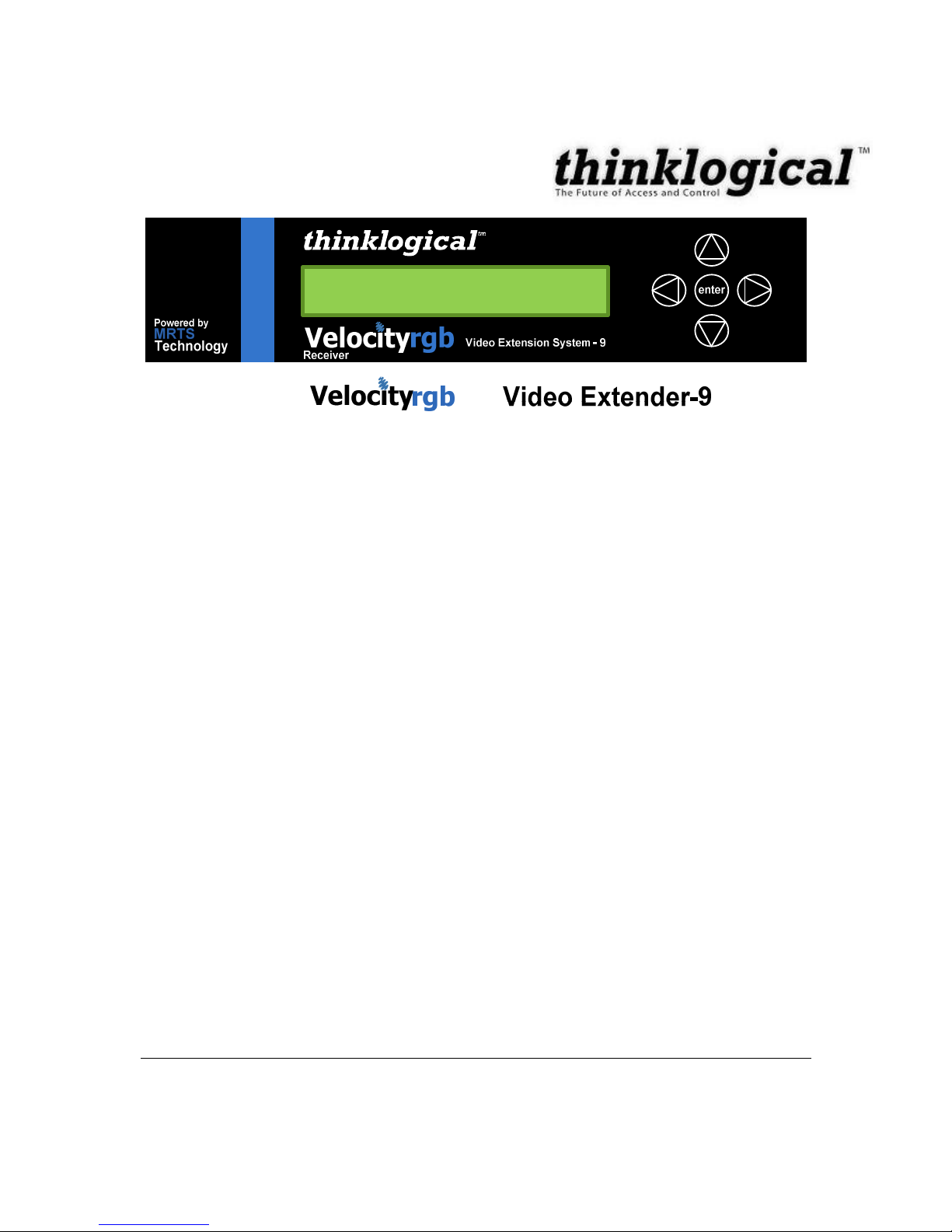
Video Extension System
–
9
Product Manual
Thinklogical Inc.
100 Washington Street
Milford, Connecticut 06460 U.S.A.
Telephone (203) 647
-
8700
Fax (203) 783
-
9949
www.thinklog
ical.com
Page 2

ii
JUNE
2009
REVISION
B
Copyright Notice
Copyright © 200
9.
All rights reserved. Printed in the U.S.A.
Thinklogical
™
, a subsidiary of Logical Solutions
™
, Incorporated
100 Washington Street
Milford, Connecticut 06460 U.S.A.
Telephone (203) 647
-
8700
Fax: (203) 783
-
9949
All trademarks and service marks are property of their respective owners.
Subject:
VelocityRGB Video
Extension System
-
9
Revision:
B:June
, 2009
Page 3

iii
JUNE
2009
REVISION
B
Table of Contents
1. INTRODUCTION
................................
................................
................................
..........................
5
1.1
CONTENTS
................................
................................
................................
........................
5
1.2
PRODUCT OVERVIEW
................................
................................
................................
......51.3
MODELS………...…………………………………………………………………………………....
6
1.4
LASER
INFORMATION……………………………………………………………………………
..72.SYSTEM FEATURES
................................
................................
................................
..................
7
2.1
G
ENERAL
S
YSTEM FEATURES
................................
................................
................................
.....
7
2.2
B
ASIC OPERATION
................................
................................
................................
.....................
8
2.3
TECHNICAL
S
PECIFICATIONS
................................
................................
................................
......93.
C
ONNECTING THE
RGB
E
XTENDER
................................
................................
................................
103
.1 Fiber Cable
................................
................................
................................
.........................
103.2RGB Video Extender
Transmitter
................................
................................
........................
10The CPU and
the TX Connector
................................
................................
.............................
10Modifying the Analog RGB Video Parameters
................................
................................
........
103.3RGB Video Extender
Receiver
................................
................................
............................
133.4ACP
OWER
……………
.……………………………………………………………………………….1
3
3.4.1T
X AND
RX
...
…..…………………………………………………………………………………1
3
4.0
O
RDER OF
I
NSTALLATION
E
VENTS
................................
................................
...............................
144.1
F
IRMW
AREUPGRADES
................................
................................
................................
.............
144.2
F
RONT
P
ANEL
U
SAGE
................................
................................
................................
..............
144.2.1
General Front Panel Usage
................................
................................
..............................
144.2.2
Saving Changes
................................
................................
................................
...............
184.3.3 Restoring Factory Defaults
................................
................................
...............................
19
4.3.4
Naming the Transmitter Unit
................................
................................
............................
204.3.
5 Modifying an Existing Video Modeline
................................
................................
..............
225
. REGULATORY AND SAF
ETY
................................
................................
................................
...265.1
S
AFE
TYREQUIREMENTS
................................
................................
................................
...........
265
.1.1 Symbols Found on Product
................................
................................
..............................
265
.1.1.1 Class 1M Laser Labeling
................................
................................
............................
265.2R
EGULATORY
C
OMPLIANCE
................................
................................
................................
......265.2.1 North America
................................
................................
................................
..................
275
.2.2 Australia & New Zealand
................................
................................
................................
..275.2.3 European Union
................................
................................
................................
...............
275
.2.3.1 Declaration of Conformity
................................
................................
...........................
275
.2.3.2 Standards with
which the Products Comply
................................
................................
285
.2.4 Supplementary Information
................................
................................
..............................
295.2.5 Product Serial Number
................................
................................
................................
.....296
. HOW TO CONTACT US
................................
................................
................................
............
306.1C
USTOMER
S
UPPORT
................................
................................
................................
...............
306
.1.1 Website
................................
................................
................................
............................
3
0
Page 4

iv
JUNE
2009
REVISION
B
6
.1.2 Email
................................
................................
................................
................................
316
.1.3 Telephone
................................
................................
................................
........................
316
.1.4 Fax
................................
................................
................................
................................
...326.2
P
RODUCT
S
UPPORT
................................
................................
................................
.................
326
.2.1 Warranty
................................
................................
................................
..........................
326
.2.2 R
eturn Authorization
................................
................................
................................
.........
326
.2.3 Our Address
................................
................................
................................
.....................
32APPENDIX A
-
QUICK
START GUIDE
................................
................................
..........................
3
3
Page 5

MAY 2009
REVISION A
5
1
Introduction
Contents
When you receive your Thinklogical
™
Velocity
RGB
-9Video
Extender, you should find the
following items:
RGB Video Extender Transmitter
RGB Video Exten
der Receiver
HD15M to HD15M cable, 2M (CBL000020
-
002MR)
Universal AC Power adapters (PWR
-
000022
-
R)CD Product Manual
1.2
Product Overview
Industry standard RGB video formats up to
165
MHz are
supported over multi
-
mode or single
-
mode
fiber. Resolutions
which fit into the
165
MHZ bandwidth will be flawlessly transported
from end to end. The V
elocity RGB
-
9 harnesses advanced fiber optic technology which means
that image quality is not compromised with problems such as frame
dropping or content loss.
Powe
red by Thinklogical's cutting edge, patent
-
pending MRTS (
M
ultiRateTransmission
S
ystem) technology, this digital video extension system transports every frame of a video
stream seamlessly, with no compression, or dropped frames. In addition, all high spee
d
peripherals function with no latency. Leveraging
standard SFP+ transceivers, the system allows
for the usage of either multi
-
mode or single
-
mode fiber optic cable.
Each system consists of a transmitter and a receiver connected by multi
-
mode or single mo
de
fiber optic cable. The transmitter unit connects to an analog video source with a suitable cable
and the receiver unit provides connections to the display device. A +5V DC power supply is
required on both the transmitter and receiver.
The Velocity RGB
-
9 requires two fibers. The transmitter supports RGB video formats up to
165MHz. In
addition
, the Velocity RGB
-
9 has a local RGB video display port on the transmitter
and is compatible with all Thinklogical Velocity fiber video receivers (except Dual
-
Link D
VI
versions), whether RGB or DVI. The receiver converts the video
signal back from optical to RGB
formats. The Velocity RGB
-
9 receiver with dual RGB outputs is offered for distributing the video
source to two displays, eliminating the need for an external
distribution amp.
Page 6
6
JUNE
2009
REVISION
B
1.3
TheModels
VEL-AV0S09
-
SCRX
Velocity 9 RGB Video Extender Receiver,
RGB, Local Display, AUX VGA
Output, Serial, Audio, Single Mode, SC/APC
VEL-
AV0S09
-SCTXVelocity 9 RGB Video Extender Transmitter
,
RGB, Local Display & VGA Port,
Serial, Audio, Single Mode, SC/APC
VEL-AV0S09
-
NKRX
Velocity 9 RGB Video Extender Receiver, RGB, Local Display, AUX VGA
Output, Serial, Audio, SM, Neutrik
®
LC/APC
VEL-AV0S09
-
NKTX
Velocity
9 RGB Video Extender Transmitter, RGB, Local Display & VGA Port,
Serial, Audio, SM, Neutrik
®
LC/APC
VOP-S05
Velocity 9 AV+ Optics Option for Transmitter or Receiver, Single Mode, Dual Fiber,
10KM, SC/APC
VOP-S11
Velocity 9 AV+ Optic
s Option for Transmitter or Receiver, Single Mode, Dual Fiber,
10KM, Neutrik
®
LC/APC
VEL-AV0M09
-
LCRX
Velocity 9 RGB Video Extender Receiver, RGB, Local Display, AUX VGA
Output, Serial, Audio, Multi
-
Mode, LC
VEL-AV0M09
-
LCTX
Velocity 9 RGB Video Extender T
ransmitter, RGB, Local Display, Local VGA
Port, Serial, Audio, Multi
-
Mode, LC
VEL-AV0M09
-
SCRX
Velocity 9 RGB Video Extender Receiver, RGB, Local Display, AUX VGA
Output, Serial, Audio, Multi
-
Mode, SC
VEL-AV0M09
-
SCTX
Velocity 9 RGB Video Extender Transmit
ter, RGB, Local Display, Local VGA
Port, Serial, Audio, Multi
-
Mode, SC
VEL-AV0M09
-
STRX
Velocity 9 RGB Video Extender Receiver, RGB, Local Display, AUX VGA
Output, Serial, Audio, Multi
-
Mode, ST
Page 7

7
JUNE
2009
REVISION
B
VEL-AV0M09
-
STTX
Velocity 9 RGB Video Extender Transmitter, RG
B, Local Display, Local VGA
Port, Serial, Audio, Multi
-
Mode, ST
VEL-AV0M09
-
NKRX
Velocity 9
RGB Video Extender Receiver,
RGB, Local Display, AUX VGA
Output, Serial, Audio, M
ulti-Mode, Neutrik
®
LC
VEL-AV0M09
-
NKTX
Velocity 9 RGB Video Extender Transmitter,
RGB, Local Display & VGA
Port, Serial, Audio, Multi
-
Mode, Neutrik
®
LC
VOP-M04
Velocity 9 AV+
Optics Option for Transmitter or Receiver, Multi
-
Mode, Dual Fiber,
50M or 350M or 1000M, LC or Neutrik
®
LC
VOP-M01
Velocity 9 AV+
Optics Option for Transmitter o
r Receiver, Multi
-
Mode, Dual Fiber,
50M or 350M or 1000M, SC or ST
1.4
Laser Information
CAUTION:
In order to avoid possible exposure to laser
energy, it is good practice to
attach the fiber optic cables prior to apply
ing power to the
RGB Video
Extender
.
If the fiber optic cable should become disconnected, DO NOT
attempt to look into the cable or the panel mounted connector.
2.
System Features
2.1.
G
eneral System
F
eatures
The
RGB Video Extender
is designed for high resolution video extension application
s. Each
RGB Video Extender
system includes the following common features:
Extends video up t
o 1000 meters
(3280 feet)
using mult
i-mode fiber
All copper cabling is industry standard
Units are stand alone and rack mountable (brackets included)
Local RGB Dis
play port on transmitter
RGB supported to 1
60
0 x 1200
Front LCD with user adjustable settings
Flawless image quality, with no frame dropping
Small package
Standard VGA (HD15) Copper Connectors
Page 8
8
JUNE
2009
REVISION
B
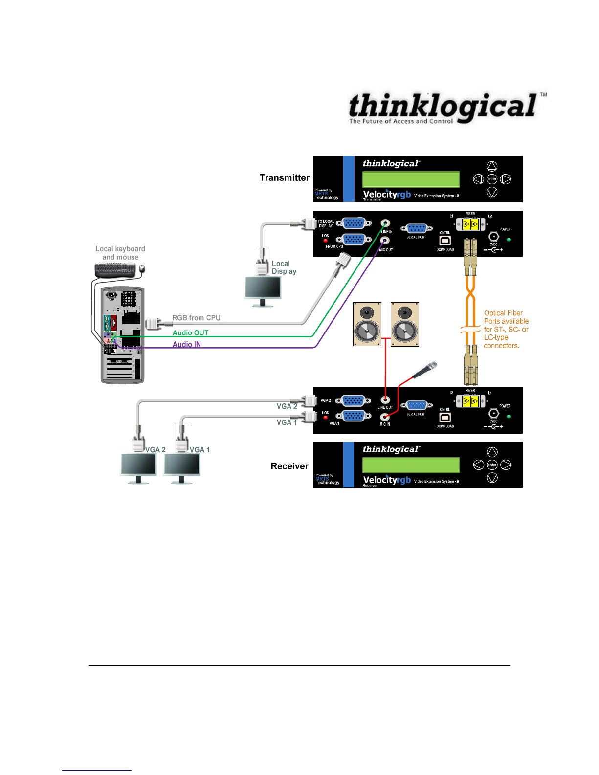
2.2
Basic operation
Page 9

9
JUNE
2009
REVISION
B
2.3Techni
calSpecifications
Storage Temperature
-
20 to 70
o
C (-4 to 158
o
F), 10 to 90% RH, non
-
condensing
Supply Voltage
100-240 VAC, 50
-
60 Hz, Universal
(supplied)
Power Consumption
Transmitter: <15 Watts, typical
Receiver: <15 Watts, typical
Heat Dissipat
ion
< 60 BTU’s per hour
Panel Connectors
Refer to Section
3.2
and
3.3
to view Rear Panels
Optical Cable
Multi
-
mode, 50 µ
m, SC, ST or LC type
connectors (Fiber Cable is either customer supplied or can be
ordered from
Thinklogical
)
Front Panel Display
T
ransmitter and Receiver: 2 x 24 Liquid Crystal Display
Operating Temperature
and Humidity
0 to 50
o
C (32 to 122
o
F), 5 to 95% RH, non
-
condensing
Enclosure Dimensions
Approx.
6.49
in x10in x 1.
19
in high
(
16.5
cm x
25.4
cm x
3.016
cm high)
Weight
T
ransmit
ter: 4 lbs (1.82 kg), Receiver: 4 lbs (1.82 kg)
Shipping Weight
Pair: 9 lbs (4.09 kg)
Copper Cables
(Supplied with system)
(1)CBL
000020
-
002M
R
HD15 (M) to HD15 (M) Cable, 2M
Page 10
10
JUNE
2009
REVISION
B
3.
Connecting the RGB Extender
3
.1 FiberCable
Fiber optic cable must
run between the location of the Transmitter unit (near your CPU) and the
Receiver unit (near your desktop devices). The standard multi
-
mode fiber optic cable must be
50micron, terminated with an SC
, ST
or LC type fiber optic connector and no longer than
3280
running feet (1000 meters). Be careful not
to
kink or pinch the fiber optic cable as it is being
installed, and keep all bend radii to no less than 3 inches (76.2mm).
Please refer to the Quick
Start Guide included in
Appendix A
on page 3
3
.
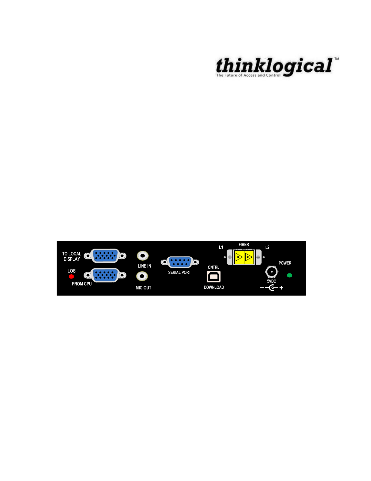
3.2RGB
Video Extender
Transmitter
If a
DVI-A
connection
from the source
is required, standard adapters are
available from
Thinklogical
and
third
party suppliers to make other combinations.
(See Table 3)
FIG
URE
7
:
V
elocity
RGB
-
9 T
ransmitter
The CPU and the TX Connector
Video connections to the CPU are made between the video output card of the CPU and the TX
VGA
connector labeled “FROM CPU” (closest to fiber connectors). The additional video
connector is for a local administrator t
o view the video output at the TX unit.
The analog VGA inputs are converted to a fiber optic suitable form and transmitted to the RX
unit.
Modifying the Analog RGB Video Parameters
It is possible for one resolution to have different video timings, which c
ould cause a less than
perfect display on the remote side. For example, take 1280x1024x60 Hz. The VESA standard
has 1688 pixels in one line, whereas a SGI format has 1680 pixels. The transmitter lookup table
is configured for the VESA standard, but can b
e easily modified to support the SGI format.
(Refer to Section 7.2.6 for step by step
instructions.)
Page 11

11
JUNE
2009
REVISION
B
FIGURE 1
4
FIGURE
15FIG
URE
14:1280x1024x60 on an SGI compu
ter with the
PLLDIV set at 1688
(default value).
Notice the columns.
FIGURE
15:1280x1024x60 on an SGI computer with the PLLDIV modified to 1680.
The following table (pg. 12) lists supported analog (VGA) resolutions
:
Page 12

12
JUNE
2009
REVISION
B
Supported Analog VGA Resolutions
Resolution
Vertical
Freq(Hz)
Horizontal
Freq(kH
z)
Pixel Clock
Freq(M
Hz)Video Standard
Pixels
Lines
640
4806031.5
25.175
Industry Standard
640
4807237.9
31.5
VESA
640
4807537.5
31.5
VESA
640
4808543.336VESA
720
4007031.5
28.32
Industry Standard
800
6005635.136VESA
800
6006037.940VESA
800
6007248.150VESA
800
6007546.9
49.5
VESA
800
6008553.7
56.25
VESA
1024
7686048.465VESA
1024
7687056.575VESA
1024
7687560
78.75
VESA
1024
7688568.7
94.5
VESA
1024
7689677.5
103.5
SGI Octane
1152
8645650.980.05
SGI PIP
1152
8647567.5
108
VESA
1152
9006661.8
94.5
Sun
1152
9007671.8
108
Sun
1280
7686047.8
79.5
VESA
1280
9606060
108
VESA
1280
9608585.9
148.5
VESA
1280
9609695.3
159.2
SGI Prism
1280
10246064
108
VESA
1280
10246064.8
108
.88
Discreet
1280
10247276.9
129.25
SGI Octane
1280
10247278.6
135.738
HPUX
1280
10247580
135
VESA
1280
10247681.1
135
Sun
1280
10247681.9
140.25
SGI
1280
10248591.1
157.5
VESA
1280
102496102
163.277
SGI Onyx2
1400
10506065.3
121.75
VESA
1400
10506067.1
128.91
SGI
1600
12006075
162
VESA
1920
10806068
163.3
SGI Onyx2
1920
10806067.5
148.5
CEA-861-E
1920
11545059.3
136.36
SGI Octane2
1920
11546071.1
163.64
SGI Octane2
1920
12004859.8
143.62
SGI Tezro
1920
12004861.9
148.442
SGI Onyx3
1920
12005064.6
154.78
SGI Tezro
1920
12006074
154
VESA
2048
11526071.1
156.75
VESA
Page 13

13
JUNE
2009
REVISION
B
3.3
RGB
Video Extender
Receiver
The receiver connects to your display/monitor video Input using a VGA, H
D15 (if monitor has a
VGA/HD15 connector).
These cables are provided with unit
.
Standard adapters are available
from
Thinklogical
and third party suppliers if necessary to make other connections.
FIG
URE
22:
Velocity RGB
-9R
eceiver
3.4
AC
Power
Two
power supplies
(PN: PWR
-
000022
-
R) are included. The
power
supply has
a
universal
power rating (1 00
-
240VAC, 50
-
60Hz) and also has interchangeable wall plugs for various
AC
power receptacles f ound throughout the world. Use the appro
priate plug f or your
country/location.
3.4.1.
Transmitter and
Receiver
AC Power Supply
Two
power supply
adapters (part number PWR
-
000022
-R)are included.
Universal Input: 100
–
240 VAC 50/60Hz Nominal
Continuous Short Circuit Protection
Over Voltage Pr
otection
Optional AC adaptors to fit various international standards
AC Power Supply (PN: PWR
-
000022
-
R) shown with
interna
tional AC
adaptor
s
Page 14

14
JUNE
2009
REVISION
B
4.
Order of Installation Events
Reference
the
Quick Start Guide in
Appendix A
on page 3
3
.
4.1
Firmware Upgrades
Firmware upgrades are
available
from Thinklogical. P
leas
e call
us
for technical assistance at
(203) 647
-
8700.
4.2
Front PanelUsage
enter
Velocityrgb
VideoExtensionSystem-
9
Technolog
y
Poweredby
MRT
S
Receive
r
LCD Navigation Pad
LCD System Information
and Programming
FIGURE 28
: Velocity
RGB
Video Exten
sion System
–9,LCD DISPLAY
4.3.1
General Front Panel Usage
Once the unit is pow
ered up, the initial display is shown as follows:
T
his displays the device typ
e and revision of the base unit.
Thinklogical
Velocity TX9
vxx.xx
Page 15

15
JUNE
2009
REVISION
B
By pres
sing the arrow
(down)
keys, the
RGB Video Extender
allows you to enter into the
main menu.
All mai
n root menu items are displayed with an *.
They are as follows:
Once an * root menu item is
displayed, you can then use the
(left)
or
(right)
arrow keys
to
review settings or m
ake changes, if allowed. The
RGB Video Extender
menu functionality is
as follows:
*
System
*DDC
*Video
Page 16

16
JUNE
2009
REVISION
B
Some menu options may not be available on some models
Display
Modifi
able
Description
*System
LS Connected
NO
An indication of the fiber status from the TX to RX.
TXCtrl Name
TX
Only
Name entered on TX unit is displayed on RX unit.
Load Defaults
YES
Loads factory default video configurations.
Store Values
YES
Store video configurations.
TX Control
NO
Revision of the TX control
firmware
.
RX Control
NO
Revision of the RX control
firmware
.
FPGA Version
NO
Revision of the
FPGA code
Serial Number
YES
Serial Number of unit.
Aud Re
set En
YES
Resets the audio sync circuitry
SFP Loss of Signal
NO
An indication of fiber status on the extender Receive channel. Value =
0 if signal is received, 1 if signal is missing.
Debug Values
YES
Factory Use
Only
.
Display
Mo
difiable
Description
*DDC–To be implemented at a later date
DDC PROM Emula. Mode
YES
Options are Dynamic, Static and Passthru.
In
Dynamic
mode, the DDC of the monitor connected to the RX is read
and
stored on the TX. The CPU is informed of a chang
e in DDC and
the monitor is
read. This is useful when the CPU can be turned on
without a connection to the
RX.
Static
mode is used to maintain the
current DDC regardless of monitor changes
at the RX.
Pass-thru
acts
as a wire between the TX and RX and no em
ulation takes place.
Load Default DDC
YES
Loads the
default EDID table into the TX and change
s
the mode to
S
tatic.
Acquire DDC
YES
Gets the EDID
table
from the monitor attached to the RX and stores it
in the TX.
Force DDC mode
YES
Set
s the EDID Video Input Signal Type to either analog or digital.
* Video
VGA Connected
NOAn indication of whether VGA video is input to the TX
Resolution
inputNO
Active pixels x active lines vertical rate
Hor. Freq
NOHorizontal freque
ncy
Auto Phase
YESAutomatically adjust the Sampling Phase to the best setting
PLL Total
YESThe total pixel count in one line.
Page 17

17
JUNE
2009
REVISION
B
Consists of Horizontal active pixels + Horizontal blanking pixels
DE Start
YESHorizontal back porch (Hpb)
of video, measured in pixels
DE Width
YESTotal active pixels in one line
Line Start
YESVertical back porch (Vbp) of video, measured in lines
Line Width
YESThe number of visible lines
NativeH
NO
For use by Tech support to determine
horizontal frequency input
U
se the following formula to calculate the frequency:
NativeH * 16
NativeV
NO
For use by Tech support to determine vertical frequency input
Use the following formula to calculate the frequency:
(10,000,000/NativeV)/16
Video 1
cntNO
Internal use only.
Video 2 cnt
NOInternal use only.
Page 18

18
JUNE
2009
REVISION
B
4.3
.2 Saving Changes
Save
video configurations so that after powering up, the device can recall customer video settings.
U
sing the down
arrow, scroll down to
*System
as shown below.
Using the
right arrow, scroll right until
Store Values
is displayed as shown below then press
enter
.
Using the
up arrow
or
down arrow
scr
oll until
Y
es
appears as shown below. Then press
enter
.
*System
Store Values
Yes/No=
NO
Thinklogical
VelocityTX9
vxx.xx
Page 19

19
JUNE
2009
REVISION
B
Using the
right arrow
or
left arrow
, scroll until you
return to the
*System
menu option. Using
up
arrow
or
down
arrow
,
scroll until you get
back
to the
Thinklogic
al
screen
.
4.3
.3 Restoring Factory Defaults
Load
factory default video configurations.
Using the
down arrow
, scroll down to
*System
as shown below.
Using the
right arrow
button,
scroll right until
Load Defaul
ts
is disp
layed as shown below. Then
press
enter
.
Using the up
arrow
or down
arrow
scroll until
Y
es
appears as shown below. Then press
enter
.
Store Values
Yes/No =
YES
*System
Load Defaults
Yes/No=
NO
Page 20

20
JUNE
2009
REVISION
B
Follow the steps in
Section
4.3
.2 Saving Changes
to
save your changes.
4.3.
4
Naming the Transmitter Unit
Modify the name of the unit through the Transmitter. The name entered on the Transmitter will
display
on the Receiver unit.
Using the arrow down button, scroll down to
*System
as shown below
.
Using the right arrow, scroll right until
Tx Ctrl
is displayed as shown below. Then press
enter
.
*System
Tx Ctrl
Name=
TXUnit01
Load Defaults
Yes/No=
YES
Page 21

21
JUNE
2009
REVISION
B
Using the
right or left
arrow,
scroll until the
blinking
cursor is unde
r the lett
er/number you want to
change.
Using the up or down arrow, scroll (holding down the up or down arrow will scroll faster) until
you find the appropriate letter/number. Then press
enter.
Using the right or left arrow, scroll to return to the
*System
menu option.
Follow the steps in
Section 2.7.2 Saving Changes
to save your changes. The steps are listed
below:
1.
Using the down
arrow
, scroll down to
*Sy
stem
as shown below.
2.
Using the right arrow, scroll right until
Store Values
is displayed as shown below
.
Then press
enter
.3.Using the up or down
arrow
scroll until
Yes
appears as shown below. Then press
enter
.
Tx Ctrl
Name=
TXUnit01
Tx Ctr
l
Name=
TXUnit11
*System
Page 22

22
JUNE
2009
REVISION
B
4.
Using the right or left arrow, scroll to ret
urn to the
*System
menu option.
5.
Using up or down arrow scroll until you get to the
Thinklogical
screen
.
4.3.
5
Modif
ying an Existing Video Modeline
Modifi
cation
to support the alternate timing.
Example of modifying an existing video modeline:
The VESA
timing for 1280x1024_60Hz (SXGA) is loaded into the Velocity
RGB
9 TX. The modeline
can be easily modified to support the alternate timing listed in the table below. Modifiable
differences are highlighted.
Parameter
Supported Timing
Alternate Timing
Res
olution
1280x1024_60
1280x1024_60 SGI Onyx
Pixel Clock (MHz)
108
107.352
Horizontal Frequency (kHz)
63.98
63.9
Vertical Refresh (Hz)
60
60
Horizontal Total Pixels
1688
1680
Horizontal Active (Pixels)
1280
1280
Horizontal Front Porch(Pixels)
4840Ho
rizontal Sync Width(Pixels)
112
120
Horizontal Back Porch(Pixels)
248
240
Vertical Total Lines (Lines)
1066
1065
Vertical active lines (Lines)
1024
1024
Vertical Front Porch (Lines)
13Vertical sync (Lines)
33Vertical Back Porch (Lines)
38
35
T
ABLE 4
Page 23

23
JUNE
2009
REVISION
B
The resolution you wish to modify must be applied to the TX video input connec
tor.Using the
arrow down, scroll down to
*Video
as shown below.
Using the right arrow, sc
roll right until
VGA
Connected
is
displayed as shown below. Then
press
enter
.
The Horizontal Pixel needs to be changed to
1680 to
reflect the Alternate Timing listed on
Table
4
. Move the cursor under the number you wan
t to change by pressing the right or left arrow.
Use the arrow up or down to increment or decrement the number. Once number is entered
correctly, press
enter
.
Using the right arrow, scroll right until
DE Start
is displayed as shown below. Then press
enter
.
Thinklogical
VelocityTX9
Vxx.xx
*Video
PLL Total
1688
Page 24

24
JUNE
2009
REVISION
B
T
he Horizontal Backporch (Pixels)
needs to be changed to
240
to reflect the Alternate Timing
listed on
Table
4
. Move the cursor under the number you want to change by pressin
g the right
or left arrow
. Use the arrow up
or down to increment or decrement the number. Once number is
entered correctly, press
enter
.
Using the right arrow, scroll right until
Line Start
is displayed as shown below. Then press
enter
.
The
Vertical
Backporch (Pi
xels)
needs to be changed to
35
to reflect the Alternate Timing listed
on
Table 4
. Move the cursor under the number you want to change by pressing the right or left
arrow. Use the arrow up or down to increment or decrement the number. Once number is
enter
ed correctly, press
enter
.
Usin
g the right or left arrow
, scroll to return to
*Video
menu option.
*Video
DE Start
248
Line Start
38
Page 25

25
JUNE
2009
REVISION
B
Follow the steps in
Section 2.7.2 Saving Changes
to save your changes. The steps are listed
below:
1.
Using the down arro
w, scroll down to
*System
as shown below.
2.
Using the right arrow, scroll right until
Store Values
is displayed as shown below.
3.
Then press
enter
.4.Using the up or down arrow scroll until
Yes
appears as shown below.
5.
Then press
enter
.
6.
Using the right or left
arrow, scroll to return to the
*System
menu option.
7.
Using up or down arrow scroll until you get to the
Thinklogical
screen
.
Page 26

26
5
.Regulatory and Safety
Compliance
Testing on some models is pending at this
time.
5
.1 Safety Requirements
5
.1.1 Symbols Foun
d on Product
Markings and labels on the product follow industry
-
standard conventions. Regulatory markings
found on the products comply with requirements.
5
.1.1.1 Class 1
Laser Labeling
LASER RADIATION
DO NOT VIEW DIRECTLY WITH OPTICAL
INSTRUMENTS
5
.2 RegulatoryCompliance
TheThinklogical
Inc.
Velocity
RGB
Video Exten
sion 9
products are designed and made in the
USA. The
RGB Video Extender
products have been tested by a nationally recognized testing
laboratory and found to be compliant with the following standards (both domes
tic USA and
many international locations).
Page 27

27
JUNE
2009
REVISION
B
5
.2.1 North America
These products comply with the following standards:
Safety
UL60950:2000
CAN/CSA C22.2 No. 60950
-00Laser Safety
CDRH 21 CFR 1040.10
Class 1 laser Product
Accession Number TBD
Electroma
gnetic Interference
FCC CFR
47, Part 15, Class 1
Industry Canada ICES
-
003 Issue 2, Revision 1
5
.2.2 Australia & New Zealand
This is a Class A product. In a domestic environment this product may cause radio interference,
in which case the user may be r
equired to take adequate measures.
5
.2.3 European Union
5
.2.3.1 Declaration of Conformity
Manufacturers name and address:
Thinklogical, a
subsidiary
of
Logical Solutions
Inc.
100 Washington Street
Milford, CT 06460 USA
Telephone (203)647
-
8700
Page 28

28
JUNE
2009
REVISION
B
5.2.3.2 Standards with which the Products Comply
Product name
Model:
RGB Video Extender
Video Extension System
These products comply with the requirements of the Low Voltage Directive 72/23/EEC and
the EMC Directive 89/336/EEC.
Safety
IEC60950:1992 +
A1,A2,A3,A4,A11
Laser Safety
IEC60825:2001 Parts 1 and 2
Class 1 laser Product
Electromagnetic Emissions
EN55022: 1994 (IEC/CSPIR22:1993)
EN61000
-3-
2/A14:2000
EN61000
-3-
3:1994
Electromagnetic Immunity
EN55024:1998 Information Technology Equipment
-
Immuni
ty Characteristics
EN61000
-4-
2:1995 Electro
-
Static Discharge Test
EN61000
-4-
3:1996 Radiated Immunity Field Test
EN61000
-4-
4:1995 Electrical
Fast Transient Test
EN61000
-4-
5:1995 Power Supply Surge Test
EN61000
-4-
6:1996 Conducted Immunity Test
EN61000
-4-
8:1
993 Magnetic Field Test
EN61000
-4-
11:1994 Voltage Dips & Interrupts Test
Page 29

29
JUNE
2009
REVISION
B
5
.2.4 Supplementary Information
The following statements may be appropriate for certain geographical regions and might not
apply to your location.
NOTE:
This equipment has been t
ested and found to comply with the limits for a Class
1
digital
device, pursuant to part 15 of the FCC Rules. These limits are designed to provide
reasonable protection against harmful interference when the equipment is operated in a
commercial environmen
t. This equipment generates, uses and can radiate radio
frequency energy and, if not installed and used in accordance with the instruction
manual, may cause harmful interference to radio communications. Operation of this
equipment in a residential area
maycause harmful interference in which case the user
may
be required to correct the interference at
the
user’s
expense.
NOTE:
This Class
1
digital apparatus complies with Canadian ICES
-
003 and has been verified
as being compliant within the Class
1
limits
of the FCC Radio Frequency Device Rules
(FCC Title 47, Part 15, Subpart B Class
1
), measured to CISPR 22: 1993 limits and
methods of measurement of Radio Disturbance Characteristics of Information
Technology Equipment.
This Class 1
digital apparatus meet
s all requirements of the Canadian Interference
-
Causing
Equipment Regulations.
Cet appareil numerique de la classe
1
respecte toutes les exigencies du Reglement sur le
material brouilleur du Canada.
WARNING:
This is a Class 1
product. In a domestic env
ironment this product may cause radio
interference, in which case the user may be required to take adequate measures.
5
.2.5 Product Serial Number
The
RGB Video Extender
products have a unique serial number, imprinted on a small silver
label that is place
d on the bottom of the chassis. The serial number includes a date
-
code. The
format for the date
-
code is two digits for the month; two digits for the day and
two
digits for the
year and two or three digits for a unique unit number. This serial number is
also found on the
original shipping carton.
Page 30

30
6
. How to Contact Us
6
.1 Customer Support
Thank you to our customers for choosing
Thinklogical
product
s
for your application. We
appreciate your business and are
dedicated to
helping you successfully use our
products.
Thinklogical is here to help you. To contact
Thinklogical
, use the following telephone numbers
and internet
-
based methods.
6
.1.1 Website
Check out our website for current product offerings, support information and general information
about al
l of the
Thinklogical
we offer.
Our internet website offers product information on all current systems, including technical
specification sheets and installation guides (for viewing online or for download), product
diagrams showing physical connections and
other information you might need. We are
con
tinual
ly updating our website, so be sure to “refresh” your browser when visiting the
Thinklogical
website to see the most up
-to-
date information.
Internet:
www.thinklogical.com
NOTE:
Most online documents a
re stored as Adobe Acrobat “PDF” files. If you do not have the
Adobe Acrobat reader
needed to view PDF files,
visit
www.adobe.com
for a download.
Page 31

31
6
.1.2 Email
Thinklogical is staffed Monday through Friday from 8:30am to 5:
0
0pm, Eastern Time Zone. We
wil
l try to respond to your email inquiries promptly, use the following email addresses for your
different needs:
Info@thinklogical.com
–
Information on
Thinklogical
and our products.
sales@thinklogical.com
–
Sales Department
-
orders, questions or issues
.
support@thinklogical.com
–
Product support, technical is
sues or questions, product
repairs and request for Return Authorization.
6.
1.3 Telephone
Telephone Sales:
Contact our expert technically oriented sales staff via telephone in
Milford, C
T at
(203) 647
-
8700
or if in the continental US, you may use our toll
-
free
number
(800) 291
-
3211
. We are here Monday through Friday from
8:3
0am to 5:00pm,
Eastern Time Zone. Ask for their direct dial phone number when you call.
Telephone Product Suppor
t:
Contact Product Support via telephone in Milford, CT at
(203) 647
-
8700
. The support lines are manned Monday through Friday,
8:30
am to
5
:00
pm, Eastern Time Zone.
International Sales:
Please contact our US sales staff in Milford, CT at
(203) 647
-
8700
.
We are here Monday through Friday, 8:30am to 5:
0
0pm, Eastern Time Zone (same as
New York City). If leaving a voice
message
please provide a “best time to call back” so
we may reach you at your convenience.
Our switchboard attendant will direct your
call during regular business hours. We have
an automated attendant answering our main telephone switchboard after regular
business hours and holidays. You can leave voice messages for individuals at any time.
Our Sales Representatives have direct number
s to speed up your next call to us.
Page 32

32
6
.1.4 Fax
Our company facsimile number is (203) 783
-
9949. Please indicate the nature of the fax on your
cover sheet and provide return contact information.
6
.2 Product Support
Thinklogical
’s support personnel are av
ailable Monday through Friday from 8:30am to 5:
0
0pm,
Eastern Time Zone. If your application might require assistance at some time outside of our
normal business hours, please contact us beforehand and we will do our best to make
arrangements to help you w
ith your
Thinklogical
products.
6
.2.1 Warranty
Thinklogical Inc. products carry a one year warranty, with longer term available at time of
purchase on most products. Please refer to your product invoice for your products
Warranty Terms & Conditions.
6.2.2 Return Authorization
If
for
whatever
reason you need to return your
Thinklogical
product to us, please get a
Return
Merchandise
Authorization Number (RMA#) from
Thinklogical
’s
Product Support
department
before
sending the unit in.
Return
Merchandise
Authorization must include
contact information (phone preferred) in the event we have any questions.
After receiving your R
M
A number, please ship the unit postpaid, with the R
M
A# prominently
displayed on the shipping container. We will contact you about
your product once we determine
its status.
Products received without Return
Merchandise
Authorization and/or contact information may
require additional attention on our part that may delay any desired service or support with your
system.
6
.2.3 Our Addr
ess
If you have any issue with the product, have product questions or need technical assistance
with your
RGB Video Extender
system, please call us at (203) 647
-
8700 and let us help.
If
shippin
g something with an R
M
A #
or if you’d like to write us, we a
re located at:
Thinklogical Inc.
100 Washington Street
Milford, CT 06460 USA
Page 33

33
Appendix A
–
Quick
S
tart Guide
DVI-DConnector1DVI-DConnector
2
Copyrightc2009.Allrightsr
eserved.PrintedintheU.S.A.Alltrademarksandservicemarksarethepropertyoftheir
respectiveowners.
PHONE:(
8
0
0)2
9
1
-
3211WEBSITE
:
www
.thinklogical.comEMAIL:support@thinklogical.com
Q
UICKSTARTGUID
E
Allphysicalconnecti
onstotheprodu
ctuseindustry-standardc
onnectors
.
T
M
Vis
itusonlineatwww.thinklogical.comformoreproductinformation
,
c
u
rrentupdatesandthecompletelineofThinklo
gicalproducts
.
T
M
TransmitterRece
ive
r
LocalDisplayOpticalFiberPortsavailableforST-,SC-orLC-typeconnectors
.
V
elocity
VideoExtensionSystem-
9
rgb
Thinklogical’sVideoExte
nsionSystem-9supportsRGBvid
eoformatsupto165MHzandprovideshighresolutionvideoextensionforsecurecomputerinstallati
ons
.Itisnowpossibletopositionyourremotemonit
orinanysettingfromofficetolecturehalltoboardroo
mwhilekeepingthecompute
r
s
ecureinaremote,controlledlocation.WithdualRGBoutputsontheReceiver,thevideosourcecanbe
distributedto
twoseparatedisplays,eliminatingtheneedforanexternaldistributionamplif
ier
.
T
M
Content
s
UponreceivingyourThinklogicalVelocityRGBExtenderTransmitterVelocityRGBExtenderReceiverHD15MtoHD15MCable,2Meters(CBL-000020-00
2MR)–Qty1UniversalACP
owerAdapters(PWR-000022-R)–Qty2RG
B
E
x
tenderProductManual
STEP4
ConnectthefiberopticcablesbetweentheTransmitterandReceiverUnits(upt
o1000meters).Donotkinkorpinch
thecablesandbesuretok
eepallbendradiitolessthan3inche
s
.
STEP3
Connectthes
uppliedACPowerAdapter(PWR-000022-
R)totheReceiverandplugitintoastanda
rdACsource.
4
STEP1
InstalloneortwoVGAmonitorsbyconnectingtheir
HD15cab
lestotheVGA1and/orVGA2portsontheReceiver.
STEP5
Connectth
eCPU’sR
GBvideoOUTtotheTransmitte
rwiththesup
pliedHD15MtoHD15Mcable(CBL-000020-002MR)andconnecttheCPU’saudioIN/OUTwithstandard3.5mmaudiocables.ConnecttheDB9SerialPortfromCPUtoTX,ifused.Whenlit,thegreenL
EDindicatesthat+5VDCp
owerisapplied.(AppliestobothTxandRxunits.)TheTransmitterandReceiv
erUSBportsareforfir
mware
upgradesavail
ablefromThi
nklogical
.
enter
V
e
locityrgb
Video
ExtensionSy
stem-
9
Technolog
y
Poweredby
MRT
S
R
eceiverente
r
V
e
locityrgb
Video
ExtensionSy
stem-9TransmitterSERIALPO
R
T
+
_
5VDCL1L2FIBER
TOLOCALDISPLAYFROMCPULOSLINEINMICOU
T
DOWNLOADPOWERCNTRLSERIA
LPO
R
T
+
_
5VDCL2L1FIBER
VGA2VGA1LOSLINEOUTMICIN
DOWNLOADPOWERCNTR
L
Technolog
y
Poweredby
MRTSVGA1VGA2AudioOUTAudioINRGBfromCPU
12367
8
STEP2
Conne
ctyouraudioinput/outputdevicestotheReceiver’s3.5mmaudioport
sand,ifus
ed,co
nnecttheDB9SerialPortfromRxtodevi
ce.
S
TEP
7
Conne
ctthesupp
liedACP
owerAdapter
(
P
W
R-000022-R)totheTransmitterunitandplugitint
oastandardACsource.
STEP6
Ifdes
ired,connectalo
calVGAmonitortotheTra
nsmitte
rwithanHD15MtoHD15Mcable.
STEP8
Turnonthe
C
P
U
last.Verifythatallsystemfeaturesarefunctioningproperly.
TMT
M
BothunitsfeatureaDB9SerialPorttos
upportserialconnectionsfromtheCPUtotheTransmitterandfromtheReceivertotheuser’sserialdev
ice.Whenlit,theLOS(LossOfSignal)LEDoneachunitindicateslossofavalidvideosignal.LocalkeyboardandmousePowerSupplyPowerSupp
l
y
5
VGA2VGA
1
 Loading...