


Secure Console Servers
SCS, SCS-R and Sentinel Models
Product Manual
Thinklogical, LLC®
100 Washington Street
Milford, Connecticut 06460 U.S.A.
Telephone: 1-203-647-8700 Fax: 1-203-783-9949 www.thinklogical.com
Revision K, July, 2013

Copyright Notice
Copyright © 2013. All Rights Reserved. Printed in the U.S.A.
Thinklogical, LLC®
100 Washington Street
Milford, Connecticut 06460 U.S.A.
Telephone: 1-203- 647-8700
All trademarks and services marks are property of their respective owners.
Appendix C copyright © 2003, by Multi-Tech Systems, Inc.
Subject: SCS80 / SCS160 / SCS320 / SCS480 / SCS80R / SCS160R /
SCS320R / SCS480R / Sentinel 32
Revision: K, July 2013.
|
|
Page 2 |
|
S e c u r e C o n s o l e S e r v e r M a n u a l , R e v . K , J u l y , 2 0 1 3 |
|
|
|
|
|
|
|

TABLE OF CONTENTS
PREFACE (Notes & Warnings) |
7 |
|
|
1. Introduction |
7 |
|
|
1.1 |
SCS Models Covered in this Manual |
7 |
|
1.2 |
System Features |
10 |
|
1.3 |
Software Features |
10 |
|
1.4 |
Hardware Features |
10 |
|
|
1.4.1 SCS80R, SCS160R, and SCS320R Hardware |
11 |
|
|
1.4.2 SCS480R Hardware |
11 |
|
|
1.4.3 Sentinel 32 Hardware |
11 |
|
1.5 Technical Specifications |
12 |
||
1.6 |
Documentation |
13 |
|
2. Product Overview |
13 |
|
2.1 Intended Application |
13 |
|
2.2 |
System Chassis |
14 |
|
2.2.1 SCS80 / SCS160 / SCS320 / SCS480 |
14 |
|
2.2.2 SCS80R / SCS160R / SCS320R / SCS480R |
14 |
|
2.2.3 Sentinel 32 |
14 |
2.3 |
Connecting to the SCS |
14 |
|
2.3.1 Serial Devices |
15 |
|
2.3.1.1 Break Safe |
15 |
|
2.3.2 IP Network |
15 |
|
2.3.3 AC Power |
16 |
|
2.3.3.1 SCS80 / SCS160 / SCS320 / SCS480 |
16 |
|
2.3.3.2 SCS80R / SCS160R / SCS320R / Sentinel 32 |
16 |
|
2.3.3.3 SCS480R |
16 |
|
2.3.4 DC Power |
16 |
2.4 |
User Access Control |
16 |
|
2.4.1 User Sessions |
17 |
2.5 |
Port buffers |
17 |
|
2.5.1 How to Disable Buffering |
17 |
|
|
3. Installation |
17 |
|
|
|
|
|
3.1 Mounting the SCS |
17 |
|
|
|
|
|
3.1.1 Rack Mount or Desktop |
17 |
|
|
|
|
|
3.1.2 Front Panel Display and Buttons |
18 |
|
|
|
|
|
3.1.3 Convection Cooled |
18 |
|
|
|
|
|
3.2 Connections |
18 |
|
|
|
|
|
3.2.1 Power |
20 |
|
|
|
|
|
3.2.2 AC Input |
20 |
|
|
|
|
|
3.2.3 Connecting to the Network Port |
20 |
|
|
|
|
|
3.2.3.1 SCS-R and Sentinel 32 Dual NIC Interface |
20 |
|
|
|
|
|
3.2.4 Connect your Console |
21 |
|
|
|
|
|
3.2.4.1 SCS-R and Sentinel 32 Dual Console Interface |
21 |
|
|
|
|
|
3.2.5 Connect to the Ports |
21 |
|
|
|
|
|
3.2.5.1 Automated Port Configuration Tests |
22 |
|
|
|
|
|
3.2.5.2 Port Adapters |
22 |
|
|
|
|
|
3.2.5.3 Serial Port Pin-out |
22 |
|
|
|
|
|
3.3 SCS-R and Sentinel Power Modules |
23 |
|
|
|
|
|
3.3.1 Power Module Replacement |
23 |
|
|
|
|
|
|
|
|
|
|
|
S e c u r e C o n s o l e S e r v e r M a n u a l , R e v . K , J u l y , 2 0 1 3 |
|
Page 3 |
|
||
|
|
|
|
|
|
|
|
|
|
|
|
|
|

|
3.4 |
SCS-R and Sentinel -48VDC Power Modules |
24 |
|
|
||
|
|
|
3.4.1 Wiring the -48VDC Connector |
25 |
|
|
|
|
|
|
3.4.2-48VDC Power Module Replacement |
26 |
|
|
|
|
|
4. Initial Configuration |
27 |
|
|
||
|
4.1 |
Default Configuration |
27 |
|
|
||
|
4.2 |
Initial System Security Concerns |
27 |
|
|
||
|
4.3 |
Front Panel Network Setup |
27 |
|
|
||
|
|
|
4.3.1 Front Panel Edit Mode |
27 |
|
|
|
|
|
|
4.3.1.1 Start Front Panel Edit Mode |
28 |
|
|
|
|
|
|
4.3.1.2 Program Network |
28 |
|
|
|
|
4.4 |
Initial Connection via Network |
33 |
|
|
||
|
|
|
4.4.1 Network Connection Requirements |
33 |
|
|
|
|
|
|
4.4.2 Route via Linux Workstation |
33 |
|
|
|
|
|
|
4.4.3 Route via Windows Workstation |
33 |
|
|
|
|
4.5 |
Initial Connection via Console port |
35 |
|
|
||
|
4.6 |
How to Access the LSI SCS Web Setup Interface |
35 |
|
|
||
|
|
5. System Overview |
35 |
|
|
||
|
5.1 |
SCS Systems are Linux-based |
35 |
|
|
||
|
|
|
5.1.1 Linux General Public License |
35 |
|
|
|
|
|
|
5.1.2 SCS System Architecture |
35 |
|
|
|
|
5.2 |
Initial System Administrator (sysadmin) Access |
36 |
|
|
||
|
|
|
5.2.1 Enter Commands |
36 |
|
|
|
|
|
|
5.2.2 Log Out |
36 |
|
|
|
|
5.3 |
Default Services |
36 |
|
|
||
|
|
|
5.3.1 Configure the Services |
36 |
|
|
|
|
|
6. Commands |
38 |
|
|
||
|
|
6.1 System Commands |
38 |
|
|
||
|
|
|
6.1.1 save |
38 |
|
|
|
|
|
|
6.1.2 reboot |
38 |
|
|
|
|
|
|
6.1.3 power off |
39 |
|
|
|
|
|
|
6.1.4 Other Linux Commands |
39 |
|
|
|
|
6.2 |
Change Logging Level |
41 |
|
|
||
|
|
7. System Administration |
41 |
|
|
||
|
7.1 |
Security |
41 |
|
|
||
|
7.2 |
Change Network Address |
41 |
|
|
||
|
|
|
7.2.1 Run netconfig |
41 |
|
|
|
|
|
|
7.2.1.1 Save your netconfig changes |
42 |
|
|
|
|
|
|
7.2.2 More Than One Nameserver |
43 |
|
|
|
|
7.3 |
Change Hostname |
43 |
|
|
||
|
7.4 |
Time Configuration |
43 |
|
|
||
|
7.5 |
Change NIC Speed |
43 |
|
|
||
|
7.6 |
Configure Authentications |
44 |
|
|
||
|
7.7 |
Front Panel Display Options |
44 |
|
|
||
|
|
|
7.7.1 Display Mode Parameters |
45 |
|
|
|
|
|
|
7.7.1.1 Edit |
45 |
|
|
|
|
|
|
7.7.1.2 View |
45 |
|
|
|
|
|
|
7.7.1.3 LINE_1= |
45 |
|
|
|
|
|
|
7.7.1.4 LINE_2= |
45 |
|
|
|
|
|
|
7.7.1.5 Display OFF |
46 |
|
|
|
|
|
|
|
|
|
|
|
|
S e c u r e C o n s o l e S e r v e r M a n u a l , R e v . K , J u l y , 2 0 1 3 |
|
Page 4 |
|
|||
|
|
|
|
|
|
|
|
|
|
|
|
|
|
|
|

|
|
7.8 Network Time Service |
46 |
|
|
|
|
|
7.8.1 Configure NTP |
46 |
|
|
|
|
|
7.8.2 Start the NTP Service |
46 |
|
|
|
|
|
7.9 NIS and User Port Permissions |
46 |
|
|
|
|
|
7.9.1 User Port Control |
47 |
|
|
|
|
|
7.9.2 NIS Port Access |
47 |
|
|
|
|
|
7.9.3 User Names and Groups |
48 |
|
|
|
|
|
7.9.4 NIS Database file |
48 |
|
|
|
|
|
7.9.5 NIS Make file |
48 |
|
|
|
|
|
7.9.6 NIS Configuration File |
49 |
|
|
|
|
|
7.10 NFS |
49 |
|
|
|
|
|
7.10.1 Remote NFS Directory |
49 |
|
|
|
|
|
7.11 SNMP |
50 |
|
|
|
|
|
7.11.1Start SNMP |
50 |
|
|
|
|
|
7.12 syslog |
50 |
|
|
|
|
|
7.13 Timeouts |
52 |
|
|
|
|
|
7.14 Changing Serial Port Settings |
50 |
|
|
|
|
|
7.14.1 Disable Buffering while in Interactive |
50 |
|
|
|
|
|
8. Administering Users |
51 |
|
|
|
|
|
8.1 User Setup |
51 |
|
|
|
|
|
8.1.1 adduser |
51 |
|
|
|
|
|
8.1.2 edituser |
52 |
|
|
|
|
|
8.1.3 deluser |
52 |
|
|
|
|
|
8.1.4 Other Editing Commands |
52 |
|
|
|
|
|
8.1.4.1 editbrk <name> |
52 |
|
|
|
|
|
8.1.4.2 editesc <name> |
52 |
|
|
|
|
|
9. User Operations |
52 |
|
|
|
|
|
9.1 User Accounts |
52 |
|
|
|
|
|
9.1.1 SCS users |
52 |
|
|
|
|
|
9.1.2 root user |
52 |
|
|
|
|
|
9.2 Port Identities |
53 |
|
|
|
|
|
9.3 What Users Can Do |
53 |
|
|
|
|
|
9.3.1 Access via Network |
53 |
|
|
|
|
|
9.3.1.1 Secure Shell Host (ssh) to a Port |
53 |
|
|
|
|
|
9.3.2 Access via console port |
53 |
|
|
|
|
|
9.3.3 Interactive Mode |
53 |
|
|
|
|
|
9.3.3.1 Break Sequence |
53 |
|
|
|
|
|
9.3.3.2 Escape Sequence |
54 |
|
|
|
|
|
9.4 Monitor Mode |
54 |
|
|
|
|
|
9.5 Browse the buffers |
54 |
|
|
|
|
|
9.6 Clear the Port buffers |
54 |
|
|
|
|
|
10. Regulatory & Safety |
55 |
|
|
|
|
|
10.1 Safety Requirements |
55 |
|
|
|
|
|
10.1.1 Symbols found on the Product |
55 |
|
|
|
|
|
10.2 Regulatory Compliance |
55 |
|
|
|
|
|
10.2.1 North America |
55 |
|
|
|
|
|
10.2.2 European Union |
55 |
|
|
|
|
|
10.2.2.1 Declaration of Conformity |
55 |
|
|
|
|
|
10.2.2.2 Standards to Which Our Products Comply |
55 |
|
|
|
|
|
|
|
|
|
|
|
S e c u r e C o n s o l e S e r v e r M a n u a l , R e v . K , J u l y , 2 0 1 3 |
|
Page 5 |
|
||
|
|
|
|
|
|
|
|
|
|
|
|
|
|

|
|
10.2.2.3 Supplemental Information |
56 |
|
10.3 |
Product Serial Number |
56 |
|
10.4 |
Lithium Battery |
57 |
|
10.5 |
SCS-R Models and Sentinel 32 Power Modules |
57 |
11. How to Contact Us |
57 |
||
|
11.1 |
Customer Support |
57 |
|
11.1.1 Website |
57 |
|
|
11.1.2 E-mail |
58 |
|
|
11.1.3 Telephone |
58 |
|
|
11.1.4 Fax |
58 |
|
|
11.2 |
Product Support |
58 |
|
11.2.1 Limited Warranty Information |
58 |
|
APPENDICES |
|
||
A |
File System |
60 |
|
B |
FAQ |
61 |
|
C Sentinel 32 Modem Commands |
62 |
||
D |
DC Power |
83 |
|
E Assigning IP Addresses to a Device Port |
85 |
||
F |
Adapter Pin-outs |
85 |
|
G |
Quick Start Guide |
90 |
|
S e c u r e C o n s o l e S e r v e r M a n u a l , R e v . K , J u l y , 2 0 1 3 Page 6
PREFACE
NOTES and WARNINGS
Throughout this manual you will notice certain highlighted conventions that bring your attention to important information. These are Notes and Warnings. Be sure to read each highlighted note and warning before proceeding. Examples are shown below.
!
Important Notes appear in blue text preceded by a yellow exclamation point symbol, as shown here.
A note is meant to call the reader’s attention to helpful information at a point in the text that is relevant to the subject being discussed.
Warnings! appear in red text preceded by a red stop sign, as shown here.
A warning is meant to call the reader’s attention to critical information at a point in the text that is relevant to the subject being discussed.
1. Introduction
This document pertains to the Secure Console Server (SCS) line of products developed and built by Thinklogical®, Inc. of Milford, Connecticut, USA and covers the installation, configuration and operation of all SCS models. This document also covers User and Administrator Operations, Regulatory & Safety Requirements and
Customer Support information.
1.1 SCS Models Covered in this Manual
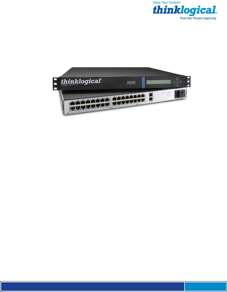
All Thinklogical® Secure Console Server (SCS) models covered in this manual are similar in physical appearance, setup and functionality. Each available model is featured on the following pages.
S e c u r e C o n s o l e S e r v e r M a n u a l , R e v . K , J u l y , 2 0 1 3 Page 7
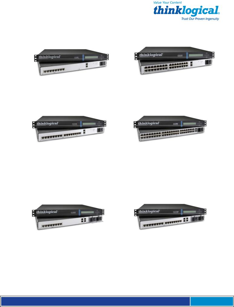
• SCS80 - 8-Port 1U Secure Console Server |
• SCS320 - 32-Port 1U Secure Console Server |
• SCS160 - 16-Port 1U Secure Console Server |
• SCS480 - 48-Port 1U Secure Console Server |
The SCS80R, SCS160R, SCS320R and SCS480R models are designed with dual hotswappable Power Modules which operate redundantly and two network ports and console port connections. The ‘R’ models are otherwise similar to the SCS80, SCS160 and SCS320.
• SCS80R - 8-Port 1U Redundant Power |
• SCS1 60R - 16-Port 1U Redundant Power |
Secure Console Server |
Secure Console Server |
S e c u r e C o n s o l e S e r v e r M a n u a l , R e v . K , J u l y , 2 0 1 3 Page 8
• SCS320R - 32-Port 1U Redundant Power |
• SCS480R - 48-Port 1U Redundant Power |
Secure Console Server |
Secure Console Server |
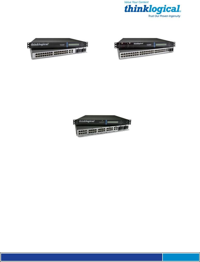
The Sentinel 32 model is designed with dual hot-swappable redundant Power Modules. In addition, the Sentinel 32 offers field replaceable, modular eight-port circuit cards, modular network and console port connections, and an analog modem option.
•Sentinel 32 - 32-Port 1U Modular, Redundant Power Secure Console Server
International Models
The following SCS models are available for International customers and are shipped with regionally appropriate power cord sets. Otherwise, each international model is similar to the domestic SCS80 / SCS160 / SCS320 / SCS480 / SCS80R / SCS160R / SCS320R / SCS480R and Sentinel 32 models.
•SCS801 - 8-Port 1 U Secure Console Server, International
•SCS1601 - 16-Port 1U Secure Console Server, International
•SCS3201 - 32-Port 1 U Secure Console Server, International
•SCS4801 - 48-Port 1 U Secure Console Server, International
•SCS801R - 8-Port 1 U Redundant Power Secure Console Server, International
•SCS1601R - 16-Port 1 U Redundant Power Secure Console Server, International
•SCS3201R - 32-Port 1 U Redundant Power Secure Console Server, International
•SCS4801R - 48-Port 1 U Redundant Power Secure Console Server, International
•Sovereign 32 - 32-Port 1 U Modular, Redundant Power Secure Console Server, International
S e c u r e C o n s o l e S e r v e r M a n u a l , R e v . K , J u l y , 2 0 1 3 Page 9

1.2 System Features
Each SCS system includes the following features:
•Linux operating system and command set
•Connections for up to 16, 32 or 48 EIA-232 serial console ports
•10 baseT/100 baseTX network compatibility
•Pre-configured from the factory: User ready, right from the box
•Open secure shell host (ssh)
•NFS and NIS support
•ssh to a Serial Port support
•Break Safe - No undesired “break” signals are sent to connected servers.
The SCS-R models also offer the following additional features:
•Dual Hot-Swappable, Redundant Power Modules
•Dual 10 baseT/100 baseTX Network Port interfaces
•Dual console port interfaces (one DTE, one DCE)
•Power Monitoring with Module outage notification
The Sentinel 32 and Sovereign 32 include the all features of the SCS-R models plus:
•Hot-swappable, modular console/network and serial port circuit cards
•Optional analog modem in place of the second console port.
1.3 Software Features
All SCS Models are designed with network administrators in mind. No special administration tools, training or procedures required. You know Linux, we run Linux.
•Open-source Linux Operating System (Red Hat compatible).
•Proprietary SCS features command-line options that follow the standard Linux / UNIX command formats for ease of administration.
•Factory pre-configured to be operational out-of-the-box.
The SCS line allows up to 250 simultaneous user sessions to access up to 48 serial ports. The attached components may be any variety of network center servers, workstations or other devices with a serial port that must be monitored.
1.4 Hardware Features
SCS systems mount in industry-standard 19” equipment racks or can be placed on a shelf or table top. Each SCS operates independently and is accessible using a secure network connection or a local serial terminal (setup by your System Administrator or
“sysadmin” ).
•Rack-mount (19 inch), 1U tall (1.75 in./ 4.5 cm) metal chassis
•16, 32 or 48 serial ports (CAT5 cables with RJ45 connectors)
•Front panel LCD with push buttons for network setup
•10/100 BaseT Network Port
•Console port (CAT5 cables with RJ45 connectors)
•Universal AC power input (100-240V, 50/60 Hz)
•Convection cooling
•256KB-per-port Buffer for Port data
S e c u r e C o n s o l e S e r v e r M a n u a l , R e v . K , J u l y , 2 0 1 3 Page 10
The SCS can help troubleshoot your networking environment. The SCS is a "listening" system that monitors messages (ASCII data, server error information, etc.) from the serial ports of the device to which each Port is connected. The SCS captures the data by writing it to a port buffer that can hold 256K bytes of data per port. This buffered data gives the sysadmin a history of console port messages that can be reviewed for troubleshooting a connected device. Having access to the console port messages can make problems easier to identify, minimizing downtime. In most cases the sysadmin can save the buffered data from each port buffer to another server (e.g., via NFS) in your network. This is important to note because the Port data (buffered) is stored in RAM and will be lost if the SCS is powered down.
!
NOTE: Console port messages are stored in RAM and will be lost when the SCS is powered down.
1.4.1 SCS80R, SCS160R and SCS320R Hardware
The SCS80R, SCS160R, and SCS320R models offer hardware redundancy for power, network and console ports. Features include dual NIC inputs, dual console port inputs and hot-swappable Power Modules with discrete inputs. This allows the customer to use redundant power sources with the SCS system and, if necessary, can be field-replaced. Power supply status alerts the system administrator in the event of a power failure from one of the power supplies.
1.4.2 SCS480R Hardware
The SCS480R offers redundant, hot-swappable, front-panel-accessible power supplies, dual NIC interfaces, dual console ports and 48 serial ports.
1.4.3 Sentinel 32 Hardware
The Sentinel 32 offers redundant power supplies as described in Section 1.4.1. The dual network and console ports are also field replaceable. A dual network/console/modem module is available which replaces the second console port with an analog modem. In addition, the Sentinel uses hot-swappable circuit modules that allow for field replacement of groups of eight serial ports without affecting the other ports.
Sentinel 32 modules:
|
Console/Network Module |
Console/Network/Modem Module |
8 Port Interface Module |
|
||
|
|
|
|
|
|
|
|
S e c u r e C o n s o l e |
S e r v e r M a n u a l , R e v . |
K , J u l y , 2 0 1 3 |
|
Page 11 |
|
|
|
|
|
|
|
|
|
|
|
|
|
|
|

1.5 Technical Specifications
Each Thinklogical® SCS system is designed to the following specifications:
User Interface
Serial Interface
(Ports)
Serial Interface
(Console)
Network interface (Network)
Modem
CPU & Memory
Power Supply
Linux command-line access via ssh or local console port. Backlit 2-line front-panel LCD display showing network configuration. Five front-panel push buttons with UI for network
SCS80/SCS80R = 8 Ports; SCS160/SCS160R = 16 Ports; SCS320/SCS320R/Sentinel 32 = 32 Ports; SCS480/SCS480R = 48 Ports. RJ45-type 8-conductor connector (DTE or DCE; software selectable). Software selectable data rate from 300-115K Baud.
Software selectable EIA-232 parameters. 256KB FIFO Buffer in RAM (per Port).
80/160/320/480: RJ45-type 8-conductor connector (DCE configuration)
80R/160R/320R/Sentinel 32: Dual RJ45-type 8-conductor connector - one DTE, one DCE
Software selectable data rate from 300-115K Baud Software selectable EIA-232 parameters
80/160/320/480: 10/100 BaseT RJ45 8-conductor Ethernet 80R/160R/320R/480R/Sentinel 32: Dual 10/100 BaseT RJ45 8-conductor Ethernet TCP/IP
A V.92 analog modem is available as an option with the Sentinel 32 for those users who require a connection over a telephone network
AMD SC520 CPU, operating at 133MHz. 256MB Compact Flash (CF) memory (nonvolatile). 128MB RAM for real time use.
Universal AC Power Input, 100-240VAC, 50/60 Hz, 0.5A each input IEC-type regional cord set(s) included. “R” Models are also available with a -48VDC Power Supply option.
Dimensions
Weight
Temperature
Relative Humidity
1U: 1.75” H x 17.25” W x 14.75” D (4.5cm x 43.8cm x 37.5cm) 4.5 kg (10 lbs)
Operating: 0° to 50°C (32° to 122°F), 30-90% RH, non-condensi |
ng |
Storage: -20° to 70°C (-4° to 158°F), 10-90% RH, non-conden |
sing |
Operating: 1090% non-condensing (40-60% recommended) |
|
Storage: 10-90% non-condensing |
|
S e c u r e C o n s o l e S e r v e r M a n u a l , R e v . K , J u l y , 2 0 1 3 Page 12

1.6 Documentation
The SCS comes with the standard Linux manual pages (hereafter referred to as “man pages”) installed; English is the default language, but several other language versions (including German, French & Italian) are also available.
While this manual gives a brief description of some LSI programs, the SCS contains the latest man pages for the LSI programs, scripts and configuration files. If the man page conflicts with this manual, the man page should be followed. Therefore, the SCS is the primary source for software documentation, not the manual. We make every effort to keep the manual current, but if you find a discrepancy, please let us know.
If ‘standard’ Linux programs (sty is one) are modified by LSI, the corresponding man pages will reflect the changes.
Selected Linux HOWTOs and READMEs can be found at /usr/local/doc. More documentation can be found at www.tldp.org.
2. Product Overview
Optimize your System Administration and Network Resources
2.1 Intended Application
Thinklogical® Secure Console Servers are used to securely monitor and centrally manage up to 48 of your networking systems (servers, routers, switches, etc.). They do so by monitoring the console port of your network center’s devices and systems. Each attached component must have an EIA-232 compatible serial port. The SCS80 and
SCS80R support 8 ports, SCS160 and SCS160R support 16 ports, SCS320, SCS320R, and Sentinel 32 support 32 ports and the SCS480 and SCS480R support 48 ports.
Security is maintained through encryption and user passwords.
The SCS80R, SCS160R, SCS320R, SCS480R, and Sentinel 32 systems are used where redundant power concerns exist, where hot-swap replacement of Power Modules is a concern or where more than one network connection or console port connection is required.
User accounts are set up by the root user, or sysadmin of the SCS. A user can access the attached servers using commands from a local terminal or through an ssh-protocol (secure) network connection. In order to interact with a device the user must have read, review or write access to that port.
Users can interact with each of the attached devices by logging into the SCS and entering the connect command and the Port number or Port name at the command prompt. The SCS acts as a conduit for the connection but does not interfere. When the user is not interacting with a network system, the SCS can log the output of the console port to a file so that data may be reviewed later.
User commands are discussed in Section 9, User Operations, beginning on page 52.
S e c u r e C o n s o l e S e r v e r M a n u a l , R e v . K , J u l y , 2 0 1 3 Page 13
2.2 System Chassis
Each SCS is housed in a rack-mountable metal chassis. Vents are found on both sides of the chassis. Removable 3-position rack mount brackets are provided. The front panel of the SCS features a two-line, backlit LCD display with five user buttons.
2.2.1. SCS80 / SCS160 / SCS320 / SCS480
Each SCS chassis has rear-panel connections for 8, 16, 32 or 48 serial ports, one console port, one network port and power input. The SCS has a built-in universal power supply, a rear-panel power switch and protective fuse.
2.2.2 SCS80R / SCS160R / SCS320R / SCS480R
Each SCS-R chassis has rear-panel connections for 8, 16, 32, or 48 serial ports, two console ports and two network ports. The SCS-R has two hot-swappable Universal Power Modules, each with its own power switch and protective fuse (located on the rear of the chassis of the SCS80R, SCS160R and SCS320R; located on the front of the chassis of the SCS480R). Each Power Module is secured with a captive mounting screw.
2.2.3 Sentinel 32
Each Sentinel 32 chassis has rear panel connections for 32 serial ports, two console ports, two network ports and two hot-swappable Universal Power Modules, each with its own power switch and protective fuse. The serial ports are arranged in four modules of eight ports each for easy field replacement. The two console and two network ports are in a single module. A module with two network ports, one console port and a V.92 modem port is available as an option. All the modules are hot-swappable.
2.3 Connecting to the SCS
All physical connections to the product are made on the rear panel using industrystandard cabling and connectors (purchased separately). All serial connections and network connections use conventional Category 5 cabling with RJ45 jacks. Power is connected using the cord set provided with each SCS system.
S e c u r e C o n s o l e S e r v e r M a n u a l , R e v . K , J u l y , 2 0 1 3 Page 14
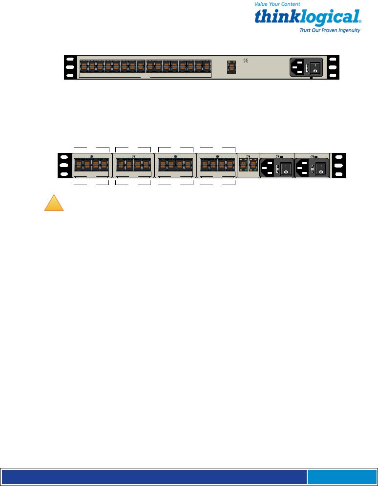
Rear View of SCS320 Chassis
Standard SCS models are similar in size and layout, offering a different number of port connectors. The SCS-R models and Sentinel 32 also have dual NIC, dual console ports and dual power inputs. The rack-mount brackets extending from both sides of each model, may be removed for desktop or shelf mounting (see page 17).
Rear View of Sentinel 32 Chassis
!
Note: Due to the modular design, the Sentinel 32 Serial Port connections on the rear of the chassis are numbered differently from the other SCS models.
2.3.1 Serial Devices
All network components attach to both the Console Ports and must be compatible with the EIA-232 standard. CAT5 cabling with RJ45 connectors are used for the Port connections and for the console port. System ports (numbered from 1 to up to 48) are default-configured as DCE data ports and support a range of baud rates from 300115.2K. All Port parameters, including DTE or DCE type and other data parameters, are configurable on a per-port basis.
Each port may also be assigned a unique name: default port names are port1, port2, etc.
2.3.1.1 Break Safe
Thinklogical® SCS systems are “break-safe,” meaning they will not send a “break” command or other data on the serial ports connected to your servers unless initiated by a user. An unwanted “break” signal could cause problems with your servers.
2.3.2 IP Network
The SCS network interface is an auto-sensing 10 BaseT/1 00 BaseTX network connector (equipped with an RJ45 jack with dual LEDs) for use with a conventional TCP/IP network using standard RJ45 CAT5 cables. A default IP address is coded into the system (10.9.8.7), but the network settings should be configured by your system administrator for your site’s requirements and equipment. SCS products are preconfigured for ssh (secure shell host) access.
S e c u r e C o n s o l e S e r v e r M a n u a l , R e v . K , J u l y , 2 0 1 3 Page 15

!
Note: The SCS-R and Sentinel 32 models offer two independent network interface ports. Only the first port (NETWORK 1) is enabled by default.
2 . 3. 3 AC Pow er
2.3.3.1 SCS80 / SCS160 / SCS320 / SCS480
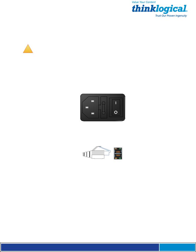
A single IEC-type Power Entry Module is located on the rear of the chassis. The power entry module incorporates a replaceable protective fuse (2A) and an On/Off switch. An
IEC cord set is provided with each SCS chassis. Connect the cord set to a local AC power source. Turn the power switch on.
2.3.3.2 SCS80R / SCS160R / SCS320R / Sentinel 32
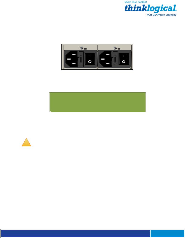
Two removable AC Power Modules, identified as Left and Right are found on the rear of the chassis. Either AC module can fully support the system and, with both turned on, operate redundantly. The SCS-R and Sentinel 32 systems have an AC power monitoring capability to alert the system administrator in the event of an AC power outage.
Each AC Module has an IEC-type power entry module. The power entry module features a replaceable, protective fuse (2A) and an On/Off switch. Two IEC cord-sets are provided with each SCS-R and Sentinel 32 chassis. Connect both cord sets to a standard AC power source. Turn both power switches ON ( l ).
 Warning! Turn the module POWER OFF and remove its power cord BEFORE removing a power module. A hazardous voltage condition might otherwise exist.
2.3.3.3 SCS480R
Two removable AC Power Modules, identified as Left and Right are found on the front of the chassis. Either AC module can fully support the system and if both are turned on, will operate redundantly. The SCS-R and Sentinel 32 systems have an AC power monitoring capability to alert the system administrator in the event of an AC power outage. A 250VAC 2A fuse is provided on each SCS480R Power Module and can be replaced when the module is removed from the unit.
2.3.4 DC Power
The Sentinel and SCS-Rs can be equipped with optional removable -48 VDC Power Modules in place of the AC Power Modules described in paragraph 2.3.3. Either module will fully power the system and will operate redundantly if power is applied to both. The power monitoring circuitry of the SCS-R and Sentinel alert the system administrator in the event of power loss to either module.
2.4 User Access Control
Access to a Port is controlled on a per-user basis via a user profile which is stored as a file on the local SCS. This profile is created by the root user using the command ‘adduser’. See
Section 8.1.1, adduser, on page 51. NIS support is also available.
S e c u r e C o n s o l e S e r v e r M a n u a l , R e v . K , J u l y , 2 0 1 3 Page 16

2.4.1 User Sessions
Each SCS supports up to 250 simultaneous user sessions.
2.5 Port Buffers
Thinklogical® Secure Console Servers provide real-time serial port data buffering. Each port buffer stores up to 256KB of data held in a separate RAM file for each attached device. The data may be viewed when no users are interacting with the attached port. Port buffers are enabled by default.
2.5.1 How to Disable Buffering
Buffering is always ON when no one is connected in Interactive mode. Buffering may be disabled during an interactive session to ensure privacy after the session ends. (See the man page for stty --buffer option.)
3. Installation
3.1 Mounting the SCS
You may choose to rack mount your SCS unit or place it on a desktop. The front panel display should be visible and front panel buttons accessible. All connections are made to the rear of the chassis.
3.1.1 Rack Mount or Desktop
SCS products may be installed either in an EIA-standard 19-inch rack (1U tall) or on a shelf or desktop. For desktop use, rubber feet are provided and the rack mount brackets may be removed. The SCS chassis does not need to be opened or accessed and the sturdy metal case allows units to be stacked as required.
Each rack mount bracket is held on by 4 screws. The brackets may be positioned so that the unit sits forward, flush or recessed in your rack. If the brackets are removed or repositioned, it is not necessary to re-install the extra rack-mount screws.
S e c u r e C o n s o l e S e r v e r M a n u a l , R e v . K , J u l y , 2 0 1 3 Page 17

3.1.2 Front Panel Display and Buttons
The front-panel LCD display should be visible and accessible during system setup. It typically displays the current network settings and the date/time. The front panel buttons are only used during setup or to review existing SCS settings.
The LCD display can be customized by the root user. See Section 7.7, Front Panel Display Options, on page 44 for more information.
3.1.3 Convection Cooled
The SCS does not require special cooling or ventilation other than what is normally provided in a standard equipment rack. No fan means that it does not add to the ambient noise in your equipment room. Be sure not to block the air vents on the sides of the unit and leave at least 2” of space on both sides. If mounted in an enclosed rack, it is recommended that the rack have a ventilation fan to provide adequate airflow through the unit(s).
!
Note: Be sure to leave a minimum of 2” of space for ventilation on both sides of the SCS chassis, especially if units are being stacked.
3.2 Connections
All connections are found on the rear panel of the SCS chassis.
Each port is clearly labeled as shown on the backpanel diagrams on page 19:
S e c u r e C o n s o l e S e r v e r M a n u a l , R e v . K , J u l y , 2 0 1 3 Page 18

SCS320 Secure Console Server
17 |
|
18 |
|
19 |
|
20 |
21 |
22 |
23 |
24 |
25 |
|
26 |
|
27 |
|
28 |
29 |
|
30 |
31 |
32 |
|||||||||||||||||||||||||
|
|
|
|
|
|
|
|
|
|
|
|
|
|
|
|
|
|
|
|
|
|
|
|
|
|
|
|
|
|
|
|
|
|
|
|
|
|
|
|
|
|
|
|
|
|
|
|
1 |
2 |
3 |
4 |
5 |
6 |
7 |
8 |
9 |
10 |
11 |
12 |
13 |
14 |
15 |
16 |
|
|
|
|
|
|
|
PORTS |
|
|
|
|
|
|
|
|
CAUTION! Replace with same type and rating fuse.
NETWORK
www.thinklogical.com
CONSOLE
100-240V -, 0.5A, 50/60 Hz  T2A, 250 VAC
SCS320R Secure Console Server
17 |
|
18 |
|
19 |
|
20 |
21 |
22 |
23 |
24 |
25 |
|
26 |
|
27 |
|
28 |
29 |
|
30 |
31 |
32 |
|||||||||||||||||||||||||
|
|
|
|
|
|
|
|
|
|
|
|
|
|
|
|
|
|
|
|
|
|
|
|
|
|
|
|
|
|
|
|
|
|
|
|
|
|
|
|
|
|
|
|
|
|
|
|
1 |
2 |
3 |
4 |
5 |
6 |
7 |
8 |
9 |
10 |
11 |
12 |
13 |
14 |
15 |
16 |
|
|
|
|
|
|
|
|
PORTS |
|
|
|
|
|
|
|
1 |
NETWORK |
2 |
www.thinklogical.com |
|
|
1 |
CONSOLE |
2 |
CAUTION! Replace with same |
100-240V -, |
type and |
0.5A, 50/60 Hz |
rating fuse. |
T2A, 250 VAC |
CAUTION! Replace with same |
type and |
rating fuse. |
100-240V -, 0.5A, 50/60 Hz  T2A, 250 VAC
SCS320M Secure Console Server
17 |
|
18 |
|
19 |
|
20 |
21 |
22 |
23 |
24 |
25 |
|
26 |
|
27 |
|
28 |
29 |
|
30 |
31 |
32 |
|||||||||||||||||||||||||
|
|
|
|
|
|
|
|
|
|
|
|
|
|
|
|
|
|
|
|
|
|
|
|
|
|
|
|
|
|
|
|
|
|
|
|
|
|
|
|
|
|
|
|
|
|
|
|
1 |
2 |
3 |
4 |
5 |
6 |
7 |
8 |
9 |
10 |
11 |
12 |
13 |
14 |
15 |
16 |
|
|
|
|
|
|
|
|
PORTS |
|
|
|
|
|
|
|
NETWORK NETWORK |
CAUTION! Replace with same type and rating fuse. |
|
1 |
2 |
|
www.thinklogical.com
CONSOLE MODEM
100-240V -, 0.5A, 50/60 Hz  T2A, 250 VAC
SCS320RM Secure Console Server
17 |
18 |
19 |
20 |
21 |
22 |
23 |
24 |
25 |
26 |
27 |
28 |
29 |
30 |
31 |
32 |
NETWORK NETWORK |
CAUTION! Replace with same |
100-240V -, |
CAUTION! Replace with same |
100-240V -, |
|
type and |
0.5A, 50/60 Hz |
type and |
0.5A, 50/60 Hz |
||||||||||||||||||
1 |
2 |
rating fuse. |
T2A, 250 VAC |
rating fuse. |
T2A, 250 VAC |
||||||||||||||||
1 |
2 |
3 |
4 |
5 |
6 |
7 |
8 |
9 |
10 |
11 |
12 |
13 |
14 |
15 |
16 |
CONSOLE |
MODEM |
|
|
|
|
|
|
|
|
|
|
||||||||||||||||
|
|
|
|
|
|
|
PORTS |
|
|
|
|
|
|
|
|
|
|
|
|
|
|
SCS480 Secure Console Server
25 |
26 |
27 |
28 |
29 |
30 |
31 |
32 |
33 |
34 |
35 |
36 |
37 |
38 |
39 |
40 |
41 |
42 |
43 |
44 |
45 |
46 |
47 |
48 |
|
|
|
CAUTION! Replace with same type and rating fuse. |
||||||||||||||||||||||||||
NETWORK |
|||||||||||||||||||||||||||||||||||||||||||||||||||||
|
|
|
|
|
|
|
|
|
|
|
|
|
|
|
|
|
|
|
|
|
|
|
|
|
|
|
|
|
|
|
|
|
|
|
|
|
|
|
|
|
|
|
|
|
|
|
|
|
|
|
|
|
|
|
|
|
|
|
|
|
|
|
|
|
|
|
|
|
|
|
|
|
|
|
|
|
|
|
|
|
|
|
|
|
|
|
|
|
|
|
|
|
|
|
|
|
|
|
|
|
|
|
|
|
|
|
|
|
|
|
|
|
|
|
|
|
|
|
|
|
|
|
|
|
|
|
|
|
|
|
|
|
|
|
|
|
|
|
|
|
|
|
|
|
|
|
1 |
2 |
3 |
4 |
5 |
6 |
7 |
8 |
9 |
10 |
11 |
12 |
13 |
14 |
15 |
16 |
17 |
18 |
19 |
|
|||||||||||||||||||
PORTS
20 |
21 |
22 |
23 |
24 |
CONSOLE |
100-240V -, 0.5A, 50/60 Hz  T2A, 250 VAC
SCS480R Secure Console Server (ON/OFF Switch located on front panel)
25 |
|
26 |
|
27 |
|
28 |
29 |
|
30 |
31 |
32 |
33 |
|
34 |
|
35 |
|
36 |
|
37 |
|
38 |
39 |
40 |
41 |
|
42 |
|
43 |
|
44 |
45 |
46 |
47 |
48 |
NETWORKNETWORK CAUTION! Replace with same type and rating fuse. |
|||||||||||||||||||||||||||||||||||||||||||||
|
|
|
|
|
|
|
|
|
|
|
|
1 |
|
2 |
|
|
|
|
|
|
|||||||||||||||||||||||||||||||||||||||||||||||||||||||||||||
|
|
|
|
|
|
|
|
|
|
|
|
|
|
|
|
|
|
|
|
|
|
|
|
|
|
|
|
|
|
|
|
|
|
|
|
|
|
|
|
|
|
|
|
|
|
|
|
|
|
|
|
|
|
|
|
|
|
|
|
|
|
|
|
|
|
|
|
|
|
|
|
|
|
|
|
|
|
|
|
|
|
|
|
|
|
|
|
|
|
|
|
|
|
|
|
|
|
|
|
|
|
|
|
|
|
|
|
|
|
|
|
|
|
|
|
|
|
|
|
|
|
|
|
|
|
|
|
|
|
|
|
|
|
|
|
|
|
|
|
|
|
|
|
|
|
|
|
|
|
|
|
|
|
|
|
|
|
|
|
|
|
|
|
|
|
|
|
|
|
|
|
|
|
|
|
|
|
|
|
|
|
|
|
|
|
|
|
|
|
|
|
|
|
|
|
|
|
|
|
1 |
2 |
3 |
4 |
5 |
6 |
7 |
8 |
9 |
10 |
11 |
12 |
13 |
14 |
15 |
16 |
17 |
18 |
||||||||||||||||||
PORTS
19 |
20 |
21 |
22 |
23 |
24 |
1 |
CONSOLE |
2 |
MODEM |
100-240V -, 0.5A, 50/60 Hz  T2A, 250 VAC
SCS80 Secure Console Server
|
|
|
|
|
|
|
|
CAUTION! Replace with same type and rating fuse. |
|
|
|
|
|
|
|
|
|
NETWORK |
|
|
|
|
|
|
|
|
|
www.thinklogical.com |
|
1 |
2 |
3 |
4 |
5 |
6 |
7 |
8 |
CONSOLE |
|
|
|
||||||||
|
|
|
PORTS |
|
|
|
100-240V -, 0.5A, 50/60 Hz |
T2A, 250 VAC |
|
SCS80R Secure Console Server
|
|
|
|
|
|
|
|
|
|
|
|
|
|
|
|
|
|
|
|
|
|
|
|
|
|
|
|
|
|
|
|
|
|
|
|
|
|
|
|
|
|
|
|
|
|
|
|
|
|
|
|
|
|
|
|
|
|
|
|
|
|
|
|
|
|
|
|
|
|
|
|
1 |
2 |
3 |
4 |
5 |
6 |
7 |
8 |
|
|
||||||||
PORTS
1 NETWORK 2
www.thinklogical.com
1 CONSOLE 2
CAUTION! Replace with same |
100-240V -, |
type and |
0.5A, 50/60 Hz |
rating fuse. |
T2A, 250 VAC |
CAUTION! Replace with same |
100-240V -, |
type and |
0.5A, 50/60 Hz |
rating fuse. |
T2A, 250 VAC |
SCS160 Secure Console Server
|
|
|
|
|
|
|
|
|
|
|
|
|
|
|
|
CAUTION! Replace with same type and rating fuse. |
|
|
|
|
|
|
|
|
|
|
|
|
|
|
|
|
|
NETWORK |
|
|
|
|
|
|
|
|
|
|
|
|
|
|
|
|
|
www.thinklogical.com |
|
1 |
2 |
3 |
4 |
5 |
6 |
7 |
8 |
9 |
10 |
11 |
12 |
13 |
14 |
15 |
16 |
CONSOLE |
|
|
|
||||||||||||||||
|
|
|
|
|
|
|
|
PORTS |
|
|
|
|
|
|
|
100-240V -, 0.5A, 50/60 Hz |
T2A, 250 VAC |
SCS160R Secure Console Server
NETWORK NETWORK 1 2
www.thinklogical.com |
|
|
|
|
|
|
|
|
|
|
|
|
|
|
|
|
|
|
|
|
|
|
|
|
|
|
|
|
|
|
|
|
|
|
|
|
1 |
|
2 |
|
3 |
|
4 |
|
5 |
|
6 |
|
7 |
|
8 |
|
9 |
10 |
11 |
12 |
13 |
14 |
15 |
16 |
CONSOLE MODEM |
|||||||||||
|
|
|
|
|
|||||||||||||||||||||||||||||||
PORTS
CAUTION! Replace with same |
100-240V -, |
type and |
0.5A, 50/60 Hz |
rating fuse. |
T2A, 250 VAC |
CAUTION! Replace with same |
100-240V -, |
type and |
0.5A, 50/60 Hz |
rating fuse. |
T2A, 250 VAC |
Sentinel 32
PORTS: |
|
|
5-8 |
|
|
|
|
|
13-16 |
|
|
|
|
|
21-24 |
|
|
|
|
|
29-32 |
5 |
6 |
7 |
8 |
1 |
2 |
3 |
4 |
|
PORTS |
|
|
5 |
6 |
7 |
8 |
1 |
2 |
3 |
4 |
|
PORTS |
|
|
5 |
6 |
7 |
8 |
1 |
2 |
3 |
4 |
|
PORTS |
|
|
5 |
6 |
7 |
8 |
1 |
2 |
3 |
4 |
|
PORTS |
|
|
NETWORK NETWORK |
CAUTION! Replace with same |
100-240V -, |
CAUTION! Replace with same |
100-240V -, |
|
1 |
2 |
type and |
0.5A, 50/60 Hz |
type and |
0.5A, 50/60 Hz |
rating fuse. |
T2A, 250 VAC |
rating fuse. |
T2A, 250 VAC |
||
CONSOLE |
MODEM |
PORTS: |
1-4 |
9-12 |
17-20 |
25-28 |
|
S e c u r e C o n s o l e S e r v e r M a n u a l , R e v . K , J u l y , 2 0 1 3 Page 19
3.2.1 Power
SCS products have an internal universal Power Supply. Each SCS unit requires approximately 15W of electrical power. The switching power supply accepts nominal AC input voltage between 100-240 VAC with a frequency range of 50-60 Hz.
!
Note: The optional -48VDC Power Module is described in Section Appendix D, DC Power, on page 83.
3.2.2 AC Input
A single IEC-type AC power entry module with an integral safety fuse and power switch is located on the rear of the chassis in each AC Power Module. The power input to the chassis uses a removable IEC-type cord set. One is provided with each AC Power Module. Be sure that your AC power source is properly grounded.
3.2.3 Connecting to the Network Port
Use a conventional, fully-pinned Category 5 cable (CAT5) to connect your network to the NETWORK (RJ45) jack on the rear of the chassis.
The SCS’s network port (auto-selecting 10/100) allows remote access to the attached networking components by the users and the sysadmin functions by the root user. You can change the network parameters from the front panel of the SCS or you may ssh into the default address and make changes using Linux commands.
3.2.3.1 SCS-R and Sentinel 32 Dual NIC Interface
The SCS80R / SCS160R / SCS320R / SCS480R / Sentinel 32 have dual network Ports.
Initially, only the first NIC is functional (NETWORK 1 = device eth0). The second NIC
(NETWORK 2 = device eth1) must be enabled by the sysadmin.
To configure the second NIC, the sysadmin will log in and use one of the following commands:
netconfig -d eth1 or netconfig --device=eth1
Refer to Section 6 for other System Commands.
S e c u r e C o n s o l e S e r v e r M a n u a l , R e v . K , J u l y , 2 0 1 3 Page 20
3.2.4 Connect Your Console
The console port is used for local access to the SCS. Connect your terminal or computer to the console port with a terminal emulation package. The SCS’s console port has a DCE configuration with adjustable parameters.
The default communication parameters for the console port are:
•9600 baud
•8 data bits
•No parity
•1 stop bit
•Xon/Xoff flow control
Use a conventional CAT5 cable to connect your terminal or computer to the CONSOLE jack (RJ45) on the rear of the chassis.
Login to the SCS: When connected to the SCS, the login as prompt will appear. Log
in as root. Press Enter to continue.
The password: prompt comes up next. Enter root (the default root password) and press Enter.
3.2.4.1 SCS-R and Sentinel 32 Dual Console Interface
The SCS80R / SCS160R / SCS320R / SCS480R / Sentinel 32 have dual Console Ports, with
Console Port 1 pinned as DCE and Console Port 2 pinned as DTE. Console Port 2 is disabled in the default configuration. To use the second console port, the sysadmin must enable it.
Console Port 2 is activated by editing the file /etc/inittab. Refer to Section 6 for other System Commands.
3.2.5 Connect to the Ports
Any system (e.g., server, router, switch) with a serial port may be connected to the SCS for consolidated system administration. Server Ports are individually configurable. Consult your server documentation as needed.
S e c u r e C o n s o l e S e r v e r M a n u a l , R e v . K , J u l y , 2 0 1 3 Page 21

The default communication parameters for the server Ports are:
•9600 baud
•8 data bits
•No parity
•1 stop bit
•Xon/Xoff flow control
•DCE Port type
Each Port can be individually configured for baud rates of 300-115K for specified data parameters and as DTE or DCE types.
!
Note: Ports may also be individually disabled if desired.
3.2.5.1 Automated Port Configuration Tests
A script named pm is available to test the device ports and report the correct DTE/DCE setting for each port. A man page exists for pm. This can be used to troubleshoot SCS to server connections. Hardware signals from the server are tested but Baud rates are not.
3.2.5.2 Port Adapters
You may need to adapt the cable connection for your server device. Thinklogical® offers serial- to-RJ45 adapters for serial ports, both DB9 and DB25, for many common network-equipment product applications. See Appendix F on page 85 for more information.
3.2.5.3 Serial Port Pin-out
Serial Port pin-out
S e c u r e C o n s o l e S e r v e r M a n u a l , R e v . K , J u l y , 2 0 1 3 Page 22
3.3 SCS-R and Sentinel Power Modules
The SCS80R, SCS160R, SCS320R, and Sentinel 32 provide dual AC Power Modules which are field-replaceable and connect to the rear panel of the SCS chassis. Each Power Module has a power entry connection with an IEC-type power connector.
The SCS80R, SCS160R, SCS320R, and Sentinel 32 have a power monitoring display shown on the front panel to indicate if one of the power supplies is not powering the system (either AC power failure, a Module is turned off or the supply has failed).
SCS Front Panel display: Left Power Supply failure
The SCS480R Power Module is mounted in the front panel of the SCS480R. It has the same capabilities as the SCSR and Sentinel Modules. It is not necessary to remove the AC power cord from the SCS480R when replacing a module.
!
Note: The Power Modules in the SCS160/320/480 are not field serviceable. This option applies to the SCS80R, SCS160R, SCS320R, SCS480R and Sentinel 32 only.
Each Power Module can fully support the SCS80R, SCS160R, SCS320R, SCS480R and
Sentinel 32 system. However, the intended design is to have two power sources running your SCS system. When both supplies are active, they will share the system load. If one fails, the remaining supply can then take the full load.
The SCS80R, SCS160R, SCS320R, SCS480R, and Sentinel 32 ship with two AC power cords, one for each module, to allow separate AC power source connections. Plug the IEC connection into the SCS AC Power Module and connect the AC cord to a standard AC power source.
3.3.1 Power Module Replacement
The Power Modules of the SCS-R and Sentinel 32 Models may be hot-swapped. Each slide-in Power Module is held in place with a single captive screw and does not need to be removed except for replacement.
S e c u r e C o n s o l e S e r v e r M a n u a l , R e v . K , J u l y , 2 0 1 3 Page 23

Captive Mounting
Screw
Handle
AC Power Module (removed from SCS Chassis)
SCS80R, SCS160R, SCS320R and Sentinel 32:
If the front panel display indicates that one of the power supply modules has failed, it may need to be replaced.
A single captive screw (visible from the rear of the SCS80R, SCS160R, SCS320R or
Sentinel 32 chassis) holds the Power Module in place and also establishes a protective Earth ground. Be sure to turn off the failed power module and remove its power cord connection. Unscrew the module and remove it from the chassis using the built-in handle on the front of the module.
SCS480R:
If you need to replace one of the SC480R power supply modules, note that the module slides in and out from the front of the chassis.
A single captive screw (visible from the front of the SCS480R chassis) holds the Power
Module in place and also establishes a protective Earth ground. Be sure to turn off the failed power module (press switch to O position). It is not necessary to remove the power cord. Unscrew the module and remove it from the chassis using the built-in handle on the front of the module.
Insert the replacement power module and tighten the screw. Reconnect the power cord if necessary and turn on the switch. When power is restored the failure message on the front panel display will clear.
3.4 SCS-R and Sentinel -48VDC Power Modules
The SCS80R, SC160R, SCS320R, and Sentinel 32 provide dual -48VDC Power Modules which are field-replaceable and connect to the rear panel of the SCS chassis. Each Power Module has a Power IN port with a WAGO MCS power connector. The SCS80R, SCS160R, SCS320R and Sentinel 32 have a front panel display to indicate if one of the power supplies is not powering the system (either DC power failure, a Module is turned off, or the supply has failed).
S e c u r e C o n s o l e S e r v e r M a n u a l , R e v . K , J u l y , 2 0 1 3 Page 24
The SCS480R Power Module is mounted in the front panel of the SCS480R and has the same capabilities as the SCSR and Sentinel Modules. It is not necessary to remove the DC power cord from the SCS480R when replacing a module.
!
Note: The Power Modules in the SCS160/320/480 are NOT FIELD SERVICEABLE. This option only applies to the SCS80R, SCS160R, SCS320R, SCS480R and Sentinel 32.
Each -48VDC Power Module can fully support the SCS80R, SCS160R, SCS320R, SCS480R and Sentinel 32 systems. However, the intended design is to have two power sources running your SCS system. When both supplies are active, they will share the system load. If one fails, the remaining supply can then take the full load.
The SCS80R, SCS160R, SCS320R, SCS480R and Sentinel 32 ship with two WAGO MCS connectors, one for each module, to allow separate DC power source connections. Plug the WAGO MCS connector into the SCS DC Power Module and connect to a regulated
DC power source.
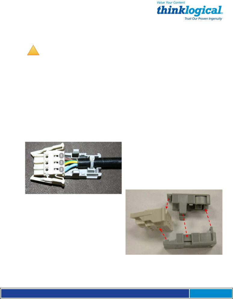
3.4.1 Wiring the -48Vdc Connector
WAGO MCS DC Power Connector:
1. Brown = -48VDC
2. Green/Yellow = Chassis Ground
3. Blue = Common
The WAGO DC Power Connector consists of 3 pieces: The connector plug and two halves of the strain-relief back shell. After installing the wires as depicted above, the three pieces fit together as shown (right) and snap firmly into place.
S e c u r e C o n s o l e S e r v e r M a n u a l , R e v . K , J u l y , 2 0 1 3 Page 25

3.4.2 -48VDC Power Module Replacement
The Power Modules of the SCS-R and Sentinel 32 Models may be hot-swapped if necessary. Each slide-in Power Module is held in place with a single screw and does not need to be removed except for replacement.
-48VDC Power Module and WAGO Connector (shown removed from Sentinel 32)
SCS80R, SCS160R, SCS320R, and Sentinel 32:
If the front panel display indicates that one of the power supply modules has failed, it may need to be replaced.
A single captive screw (visible from the rear of the SCS80R, SCS160R, SCS320R, or Sentinel
32 chassis holds the Power Module in place and also establishes a protective Earth ground. Be certain to turn off the failed power module (press switch to O position), then remove its power cord connection. Unscrew the module and remove it from the chassis using the builtin handle.
SCS480R:
If the front panel display indicates that one of the power supply modules has failed, it may need to be replaced. The power modules insert from the front of the chassis.
A single captive screw, visible from the front of the SCS480R chassis, holds each Power
Module in place and establishes a protective Earth ground. Be certain to turn OFF the failed power module by pressing the switch to the OFF (O) position). Unscrew the failed module and remove it from the chassis using the built-in handle.
You may now Insert the replacement power module and tighten the captive screw. Connect the power cord to the module and turn the switch ON ( l ). When power is restored, the failure message on the front panel display will clear.
S e c u r e C o n s o l e S e r v e r M a n u a l , R e v . K , J u l y , 2 0 1 3 Page 26

4. Initial Configuration
The SCS is Pre-Configured. Just set your IP Address and add Users.
4.1 Default Configuration
The SCS is pre-configured right out of the box, ready to generate ssh keys with an IP address set to a generic default value of 10.9.8.7 / NetMask 255.0.0.0. It is likely that the sysadmin will want to change to a local IP address.
When you first connect the unit to your network and turn the power on it will take about two minutes for the SCS to perform the initial ssh key generation. The front panel display will show the following display after the SCS’s power-up is complete and the system is ready:
SCS Front Panel Display default, normal mode shown
The top line of the display is the SCS’s host and domain name and the second line is a clock display showing day and date (initially set to Eastern Time Zone).
4.2 Initial System Security Concerns
The first login will require several steps to fully secure the SCS.
When you first connect the SCS and turn it on, it will build the ssh keys during the first two minutes of system startup. During this time, the front panel LCD second line will read start sshd, and the console port will read Starting sshd.
The root user should also configure the dual console/modem are disabled.
the ntp and the ssh config files. Network 2 and Root is not allowed to login on console 2.
4.3 Front Panel Network Setup
If you changed the network settings via netconfig, you can skip this section.
The Front Panel Display and buttons can be used to set the basic network parameters. There are four arrow buttons (Left, Right, Up, Down) and one enter button. The front panel can be used to change the IP Address, Subnet Mask, and Gateway settings. By default, the front panel will show the Host name and the Date/Time.
4.3.1 Front Panel Edit Mode
By default the Front Panel Display’s Edit mode is enabled. The View mode is similar to Edit mode except that the front panel cannot be used to change the settings. This is described in
Section 7.7, Front Panel Display Options on page 44 of this manual.
!
Note: The Front Panel Edit Mode can be disabled if desired. See Section 7.7, Front Panel Display Options beginning on page 44.
S e c u r e C o n s o l e S e r v e r M a n u a l , R e v . K , J u l y , 2 0 1 3 Page 27
 Loading...