

Thinklogical Velocitykvm-4, Velocitykvm-5, Velocitykvm-8, Velocitykvm-24, Velocitykvm-28 User Manual
...Page 1

Fiber-Optic Extension Systems
Velocitykvm-4, 5, 8, 24, 28, 34, 35 & 38
Single & Dual-Link/Single & Multi-Mode
Thinklogical, LLC®
100 Washington Street
Milford, Connecticut 06460 U.S.A.
Telephone: 1-203-647-8700
Fax: 1-203-783-9949
www.thinklogical.com
Page 2

Copyright Notice
Copyright © 2014. All rights reserved. Printed in the U.S.A.
Thinklogical, LLC ®
100 Washington Street
Milford, Connecticut 06460 U.S.A.
Telephone: 1-203-647-8700
Fax: 1-203-783-9949
www.thinklogical.com
All trademarks and service marks are property of their respective owners.
Subject: VelocityKVM Fiber-Optic Extension Product Manual
Revision: B, January, 2014
V e l o c i t y K V M E x t e n d e r P r o d u c t M a n u a l , R e v . B , J a n u a r y , 2 0 1 4 Page 2
Page 3

Table of Contents
PREFACE................................................................................................................................... 5
Conventions Used in this Manual ............................................................................................ 5
Laser Information ...................................................................................................................... 5
INTRODUCTION ........................................................................................................................ 6
The Logical Solution ................................................................................................................. 6
Theory of Operation .................................................................................................................. 6
The Fiber Extension System .............................................................................................. 6
Multi-Mode Fiber ............................................................................................................. 7
Single-Mode Fiber ........................................................................................................... 7
Options Part Numbers ........................................................................................................ 8
System Features ....................................................................................................................... 9
VelocityKVM Extender Options ................................................................................................ 9
Technical Specifications (Table 1) ......................................................................................... 13
Velocity Unbalanced Audio Specifications (Table 2) ............................................................ 14
VelocityKVM-5 Supported RGB Resolutions (Table 3) ......................................................... 15
HARDWARE ............................................................................................................................ 16
Contents .................................................................................................................................. 16
Desktop or Rack Mount Device ......................................................................................... 16
Cooling ............................................................................................................................... 17
Front Panel Display and Buttons ...................................................................................... 17
Connecting the VelocityKVM Extender ................................................................................. 17
Types of Connectors .............................................................................................................. 17
Fiber Cable ......................................................................................................................... 17
Transmitter ......................................................................................................................... 17
Receiver .............................................................................................................................. 17
Receiver Serial Port ........................................................................................................... 18
Rear Panel Views and Hardware Connections ...................................................................... 19
Typically Used Fiber and Copper Cables ........................................................................ 19
Peripheral and Update Ports ............................................................................................ 19
Fiber and Video Ports ....................................................................................................... 20
Cables ...................................................................................................................................... 24
Installation ............................................................................................................................... 26
Set Up ................................................................................................................................... 26
Firmware Upgrades ........................................................................................................... 26
Front Panel Usage .................................................................................................................. 26
General Front Panel Usage ............................................................................................... 27
SFP LOS and SFP Des OK Signals ............................................................................... 27
SFP LOS and SFP Des OK Signals (Table 4) ................................................................ 28
Saving Changes ................................................................................................................. 32
Restoring Factory Defaults ............................................................................................... 33
Naming the Transmitter Unit ............................................................................................. 34
REGULATORY & SAFETY COMPLIANCE .............................................................................. 35
Safety Requirements .............................................................................................................. 35
Symbols Found on Our Products ..................................................................................... 35
Regulatory Compliance ..................................................................................................... 35
North America .................................................................................................................... 35
Australia & New Zealand ................................................................................................... 36
European Union ................................................................................................................. 36
Declaration of Conformity ............................................................................................ 36
Standards with Which Our Products Comply ....................................................................... 36
V e l o c i t y K V M E x t e n d e r P r o d u c t M a n u a l , R e v . B , J a n u a r y , 2 0 1 4 Page 3
Page 4

Supplementary Information.................................................................................................... 36
Product Serial Number ........................................................................................................... 37
Connection to Our Products .................................................................................................. 37
HOW TO CONTACT US ........................................................................................................... 38
Customer Support .................................................................................................................. 38
Website ................................................................................................................................ 38
Email ................................................................................................................................... 38
Telephone ........................................................................................................................... 38
Fax ...................................................................................................................................... 39
Product Support ...................................................................................................................... 39
Limited Warranty Information ........................................................................................... 39
APPENDIX A: Thinklogical’s Full Line of VelocityKVM Extenders ...................................... 41
Part Number Reference Guide ......................................................................................... 44
APPENDIX B: Quick Start Guides .......................................................................................... 45
VelocityKVM-4 ................................................................................................................... 45
VelocityKVM-5 ................................................................................................................... 46
VelocityKVM-8 ................................................................................................................... 47
VelocityKVM-24 ................................................................................................................. 48
VelocityKVM-28 ................................................................................................................. 49
VelocityKVM-34 ................................................................................................................. 50
VelocityKVM-35 ................................................................................................................. 51
VelocityKVM-38 ................................................................................................................. 52
APPENDIX C: Automatic Fail-Over Option ............................................................................ 53
APPENDIX D: Keyboard Mouse Audio Control Options...................................................... 55
APPENDIX E: Separate Data Path, Separate Audio Path and Multi-Path Video Options ... 56
APPENDIX F: EDID Definitions and DDC Modes .................................................................. 60
V e l o c i t y K V M E x t e n d e r P r o d u c t M a n u a l , R e v . B , J a n u a r y , 2 0 1 4 Page 4
Page 5
PREFACE
Conventions Used in this Manual
Throughout this manual you will notice certain conventions that bring your attention to important
information. These are Notes and Warnings. Examples are shown below.
Note: Important Notes appear in blue text preceded by a yellow exclamation point symbol,
as shown here.
A note is meant to call the reader’s attention to helpful information at a point in the text that is relevant to
the subject being discussed.
Warning! All warnings appear in red text preceded by a red stop sign, as shown here.
A warning is meant to call the reader’s attention to critical information at a point in the text that is relevant
to the subject being discussed.
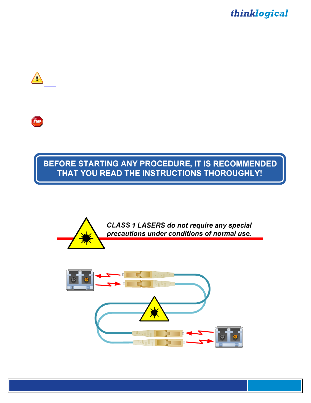
Laser Information
VelocityKVM Extenders
Modules
are designed and identified as
SFP
Class 1 LASER products.
Class 1 Lasers
Fiber-Optic
Cables
V e l o c i t y K V M E x t e n d e r P r o d u c t M a n u a l , R e v . B , J a n u a r y , 2 0 1 4 Page 5
Page 6

INTRODUCTION
The Logical Solution
VelocityKVM Fiber-Optic Extension Systems
visual applications that require video as well as peripheral support. The system allows users, via
fiber-optic cable, to station and operate video monitors and peripherals up to 40 kilometers away from
the controlling computer, securely and without loss of resolution. The VelocityKVM system is designed
to support PS2, full duplex stereo audio, serial (RS-232) and USB 1.0 (HID).
Available options include:
• Single-Mode or Multi-Mode Optics
• USB HID only (eliminates USB 2.0 for added security)
• Separate Data Paths for keyboard/mouse (See Appendix E, pg. 56)
• Separate Audio Paths (See Appendix E, pg. 56)
• Multi Path (Multiple Video Paths) (See Appendix E, pg. 56)
• RS-422 serial port for controlling broadcast equipment
• Automatic Fail-Over (See Appendix C, pg. 53)
• Professional Audio TOSLINK, AES and S/PDIF plug-in modules (pg. 12)
VelocityKVM products are ideally suited for a wide range of applications in the broadcast and postproduction field, as well as command/control centers, universities, large scale digital signage and other
commercial KVM applications.
See Option Configuration Diagrams (pgs. 10-12) and Appendix A, Complete Line of Thinklogical’s
VelocityKVM Extenders (pg. 41).
are designed for high performance
Theory of Operation
MRTS Technology 6.25 Gbps. Allows Full Frame Rate Transmission of Uncompressed DVI
Powered by Thinklogical’s cutting edge, patent-pending MRTS (Multi Rate Transmission System)
Technology, this KVM extension system transports every frame of a DVI or RGB video stream seamlessly with no compression or dropped frames. In addition, all high speed peripherals function with no
latency.
The VelocityKVM Extension System
The VelocityKVM Extension System has a simple transmitter/receiver design which allows for ease of
installation and straight-forward deployment. Incorporating standard SFP+ transceivers, the transmitter
and the receiver can be connected by a multi-mode or single-mode fiber optic cable, depending on the
user’s needs. The transmitter unit connects to the CPU with the supplied peripheral cables. In addition,
a local video, keyboard and mouse port is available on the transmitter. The receiver unit provides
connections to the various user interface devices.
V e l o c i t y K V M E x t e n d e r P r o d u c t M a n u a l , R e v . B , J a n u a r y , 2 0 1 4 Page 6
Page 7
The Fiber System
Each system includes a transmitter and a receiver connected by fiber optic cables. The transmitter
connects to the source computer with standard cables and the receiver provides connections to the user
interface devices. Standard VelocityKVM Extenders support PS2, full duplex stereo audio, serial
(RS-232), USB HID and USB 2.0.
Why Fiber?
In heavy-volume, metropolitan area networks, the limit on how much bandwidth or data that can be
carried across a copper line can become a bottleneck for enterprise access and ultimately, for revenue.
Fiber Optic Cable alleviates this problem by offering substantially greater bandwidth.
Multi-Mode Fiber
Transmission Distance (up to 350m using 50/125µm fiber)
Multi-mode is designed for transmission distances such as those found within a single building or facility
and thus, is ideal for multi-channel television broadcast systems. Multi-mode may be used to send video
signals from room to room or floor to floor. The Multi-Mode VelocityKVM Extender allows video and
peripheral transmission distances up to 350 meters using 50/125µm fiber, making it an ideal solution for
in-house applications.
Single-Mode Fiber
Transmission Distance (up to 40 kilometers)
Single-mode is designed for long distance transmissions and thus, is ideal for multi-channel broadcast
systems. Single-mode may be used to send video signals from workstation to workstation, from building
to building, or from studio to transmitter (STL) with a video resolution of 1920 x 1200. Using 9µm fiber
with SM/UPC connectors, the Single-Mode VelocityKVM Extender allows video and peripheral
transmission distances up to 40 kilometers, (25 miles) making it an ideal solution for metropolitan area
networks and most other applications.
V e l o c i t y K V M E x t e n d e r P r o d u c t M a n u a l , R e v . B , J a n u a r y , 2 0 1 4 Page 7
Page 8
Advanced Top Quality Video Transmission
Fiber optic cable has emerged as a logical solution for next-generation signal routing. The VelocityKVM
product family harnesses this capability and ensures long distance, error-free transmission with no frame
or bit dropping and complete immunity to interference. The end result is no degradation of the video
or peripheral signal whatsoever.
Options Part Numbers
Each model’s part number indicates features included on that particular model. See pages 10-12 for the
full line of VelocityKVM Extender options. Also see page 44 for more on numbering formats.
VEL-WR0M04-SCTX:
VelocityKVM 1 DVI Display Transmitter with USB HID, USB 2.0 and redundant, multi-mode fiber paths
L
1
DVI IN
L
2
'
L
1
DVI O
L2'
SER IAL POR
UT
STEREO
EMITTER
INPUT
LINE IN
MIC OUT
T
P
S
2
HID
LOCAL
OM CP
F
R
UPDATES
USB HID
LIN
K
USB
HOS
T
U
DEV
2.0
CAUTION! Replace with same type and
HOST
CTRL
100-240V-,0.5A, 50/60 H
rating fuse.
USE ONLY WITH 250V FUSE
T 2A ,250VA
C
z
VEL-WR0M04-SCTX: VEL indicates the Velocity line of extenders. The part number’s leading W indicates
USB HID and USB 2.0 only (USB 1.1 is not supported). This is the standard USB configuration for our
Velocity line. R indicates redundant fiber paths. 0 is a place holder. M indicates Multi-Mode optics.
04 designates our 1 DVI Display model. SC indicates SC-Type fiber connectors. TX indicates that this unit
is a Transmitter.
VEL-H0DM24-LCRX:
VelocityKVM 2 DVI Display Receiver with USB HID only and separate multi-mode data fiber paths
VEL-H0DM24-LCRX: VEL indicates the Velocity line of extenders. The part number’s leading H indicates the
USB HID Only option (USB 2.0 is not supported). 0 is a place holder. D indicates Separate Data Paths.
M indicates Multi-Mode optics. 24 designates our 2 DVI Display model. LC indicates LC-Type fiber
connectors. RX indicates that this unit is a Receiver.
Note: Thinklogical will no longer support the hardware required for USB 1.1. Thinklogical
will continue software support for all USB 1.1 units. Contact
support@thinklogical.com.
V e l o c i t y K V M E x t e n d e r P r o d u c t M a n u a l , R e v . B , J a n u a r y , 2 0 1 4 Page 8
Page 9
System Features
Each VelocityKVM Fiber system includes the following features:
• Supports all single-link DVI video resolutions (VelocityKVM-5 analog RGB resolutions as well).
• Supports all Dual-Link DVI resolutions (VelocityKVM-8, -28, -38).
• 6.25 Gbps signal transmission via fiber optic cable; No RF interference.
• Requires one to five fiber optic cables, depending on model and application.
• Flawless image quality with no frame dropping.
• Local KVM connections on transmitter.
• Additional video output(s) on the receiver.
• Extends KVM, audio and serial signals up to 350 meters using 50/125µm multi-mode fiber and up
to 1000 meters using type OM4 fiber.
• Extends KVM, audio and serial signals up to 40 kilometers using single mode optics.
• USB HID compliant, 4-port hub.
• BNC Stereo Emitter (3D)
• Full duplex stereo audio
• USB 2.0 compliant (high speed 480 Mbps, 4 port hub).
• (Optional) IEEE1394 FireWire 9-pin hub (Requires 2 additional fiber optic cables.)
• (Optional) Automatic Fail-Over (see page 53)
• (Optional) Separate Data Paths for keyboard/mouse
• (Optional) RS-422 serial port for controlling broadcast equipment
• DDC2B/EDID complaint.
• Fully compatible with all of Thinklogical’s VXRouter line of products.
• Full keyboard and mouse emulation through the transmitter
• Simple plug and play
• Thinklogical’s VelocityKVM Extenders are designed and identified as Class 1 Laser products.
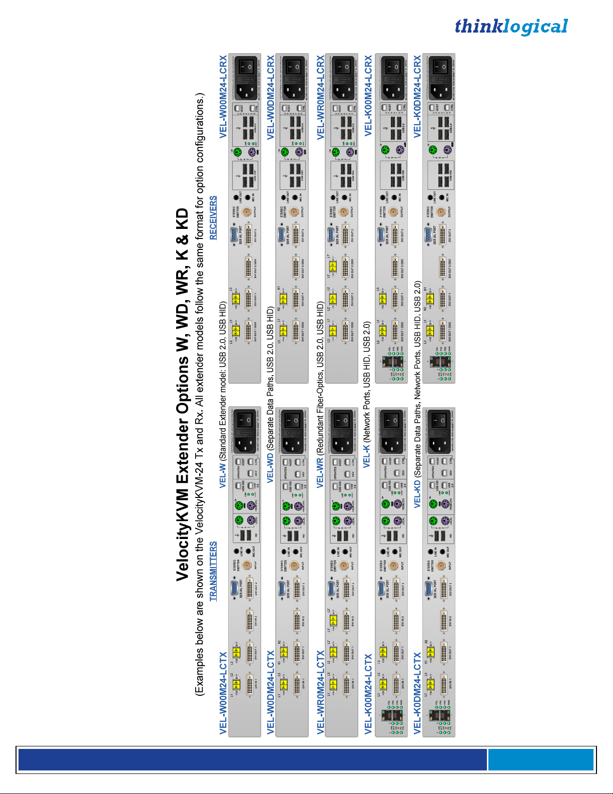
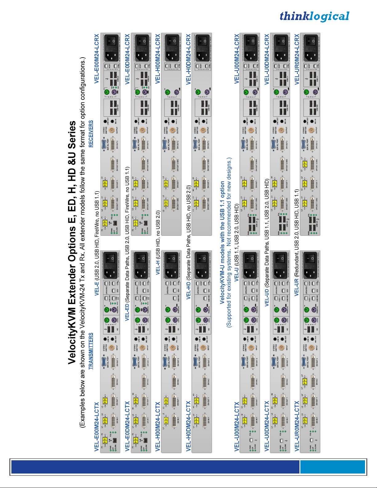
VelocityKVM Extender Options
VelocityKVM Extenders come with a variety of peripheral device options that include or
eliminate several types of USB and FireWire, Network ports and Separate Data Paths.
The examples on pages 10 -12 are shown with the VelocityKVM-24 Tx and Rx with LC-type
connectors. All extender models follow the same format for all connector types and option
configurations.
The options include combinations of, with or without, such features as:
• USB HID, USB 2.0 and/or FireWire
• Separate data paths
• 10/100 NIC Network ports
• Professional audio plug-in modules (TOSLINK, AES, S/PDIF)
Note: Thinklogical will no longer support the hardware required for USB 1.1. Thinklogical
will continue software support for all USB 1.1 units. Contact
V e l o c i t y K V M E x t e n d e r P r o d u c t M a n u a l , R e v . B , J a n u a r y , 2 0 1 4 Page 9
support@thinklogical.com.
Page 10
V e l o c i t y K V M E x t e n d e r P r o d u c t M a n u a l , R e v . B , J a n u a r y , 2 0 1 4 Page 10
Page 11
V e l o c i t y K V M E x t e n d e r P r o d u c t M a n u a l , R e v . B , J a n u a r y , 2 0 1 4 Page 11
Page 12
VelocityKVM-24P DVI 2 Display/KVM Professional Audio Extender Option
The VelocityKVM-24P Professional Audio option includes six audio modules with each unit.
Any two types will fit at once into each transmitter and each receiver unit. The modules include
TOSLINK IN, AES IN, S/PDIF IN, TOSLINK OUT, AES OUT and S/PDIF OUT.
The VelocityKVM-24A Professional Audio option includes the same features as the -24P, but
eliminates USB 2.0 for increased security (USB HID only).
VEL-24P DVI 2 Display/KVM Professional Audio Extender
Transmitter VEL-P00M24-LCTX
L
1
AES IN
TOSLINK IN
DVI IN
1
Receiver VEL-P00M24-LCRX
L
2
AES OUT
TOSLINK OUT
DVI
OUT 1 DD
C
HOST
CTRLDEV
U
P
HOST
D
A
T
E
S
CTRL
CAUTION! Replace with s
100-240V-,0.5A, 50/60 H
CAUTION! Replace with same ty
100-240V-,0.5A, 50/60 H
L
3
L
2
SER IAL POR
T
DVI OUT 1
DVI IN
2
L
VI OUT 1
D
3
OUT 2 DD
DVI
L
1
DVI OUT 2
SER IAL POR
T
C
VI OUT
2
D
STERE
EMITTER
INPUT
STEREO
EMITTER
OUTPU
O
T
LINE IN
MIC OUT
LIN
E
MIC I
P
S
2
U
HID
OU
T
N
USB HID
FROM CP
A
L
LOC
P
S
LIN
2
DEV
UPDATES
USB HID
LIN
K
USB
HOS
T
2.0
K
USB 2.0
ame type and rating fuse.
USE ONLY WITH 250V FUSE
T 2A ,250VA
z
pe and rating fuse.
USE ONLY WITH 250V FUSE
T 2A ,250VA
z
C
C
VelocityKVM-24P Professional Audio Modules included with each unit
TOSLINK OUT
S/PDIF OUT
AES OUT AES IN
TOSLINK IN
Also available:
VEL-24A DVI 2 Display/KVM Professional Audio Extender with USB HID only
Transmitter: VEL-A00M24-LCTX, Receiver: VEL-A00M24-LCRX
S/PDIF IN
V e l o c i t y K V M E x t e n d e r P r o d u c t M a n u a l , R e v . B , J a n u a r y , 2 0 1 4 Page 12
Page 13

Technical Specifications
Thinklogical VelocityKVM systems are designed to the following specifications:
TRANSMITTER
Video System 4, 8 DVI-D (2); System 24, 28, 34, 38 DVI-D
(4); System 35 DVI-D (3); System 5 DVI-I (2)
Audio MIC/Line 3.5mm Jack
Serial Port DB9 Female
Stereo Emitter 50Ω BNC
IEEE 1394* 9-Pin FireWire (optional)
USB HID USB B
USB 2.0 USB B
USB Local Kybd. USB A
USB Local Mouse USB A
PS2 Keyboard MiniDIN 6 Female
PS2 Mouse MiniDIN 6 Female
PS2 Local Kybd. MiniDIN 6 Female
PS2 Local Mouse MiniDIN 6 Female
Copper
Connectors
Firmware Updates USB B (3)
Fiber Connectors LC, SC or ST
RECEIVER
Video System 4, 8, 28, 38 DVI-D (2); System 24, 34 DVI-D
(4), System 35 DVI-D (3); System 5 DVI-I (2)
Audio MIC/Line 3.5mm Jack
Serial Port DB9 Male
Stereo Emitter BNC
IEEE 1394* 9-Pin FireWire (optional)
USB HID USB A (4)
USB 2.0 USB A (4)
PS2 Keyboard MiniDIN 6 Female
PS2 Mouse MiniDIN 6 Female
Firmware Updates USB B
Fiber Connectors LC, SC, or ST
CBL000009-002MR, DVI-D M to M: -4, -5, -24(2), -28, -34(4), -35(3)
CBL000022-002MR, HD15 to DVI-A: -5
CBL000023-002MR, DVI-D Male to Male, Dual-Link: -8, -28, -38(2)
KIT-000005-R, Audio Kit, 6FT: 1 each
Electrical Cables
(supplied with
transmitters)
V e l o c i t y K V M E x t e n d e r P r o d u c t M a n u a l , R e v . B , J a n u a r y , 2 0 1 4 Page 13
KIT-000005-R Audio Kit contains the following:
CBL000006-006FR 6 pin MiniDIN Male to Male Cable, 6FT (2)
CBL000015-006FR USB A-B Cable, 6FT (2)
CBL000016-006FR 3.5mm Male to 3.5mm Male Plug, 6FT (2)
CBL000017-006FR DB9 Male to DB9 Female Cable, 6FT (1)
CBL000018-006FR BNC Male to BNC Male Cable, 50Ω, 6FT (1)
Page 14
Video Resolution
Power
All Single-Link DVI Resolutions: System 4, 5, 24, 34, 35
All Dual-Link DVI Resolutions: System 8, 38
Single & Dual-Link DVI Resolutions: System 28
Optical Cable
(Not supplied)
Optical Distance
Operating Temp
and Humidity
Dimensions
Weights
Supply Voltage
Consumption
Compliance
Warranty
Multi-mode Fiber Type: 50 or 62.5 µm
Single-mode Fiber Type: SM/UPC, 9 µm
Up to 65 meters with Type OM1
Up to 350 meters with Type OM2
Up to 650 meters with Type OM3
Up to 1000 meters with Type OM4
0° to 50°C (32° to 122 °F), 5% to 95% RH, non-conde nsing
Height: 1.72” (4.4cm) ± .039”; .100cm
Depth: 14.22” (36.19cm) ± .039”; .100cm
Width: 17.49” (44.5cm) ± .039”; .100cm
Weight: 11 lbs (4.99kg) each
Shipping Weight: 27 lbs (12.25 kg) Transmitter and Receiver
100-240 VAC, 47-63 Hz, Universal AC power supply
<40 Watts per unit
Approvals for US, Canada, and European Union
12 months from date of purchase. Extended warranties available.
TABLE 1: Technical Specifications
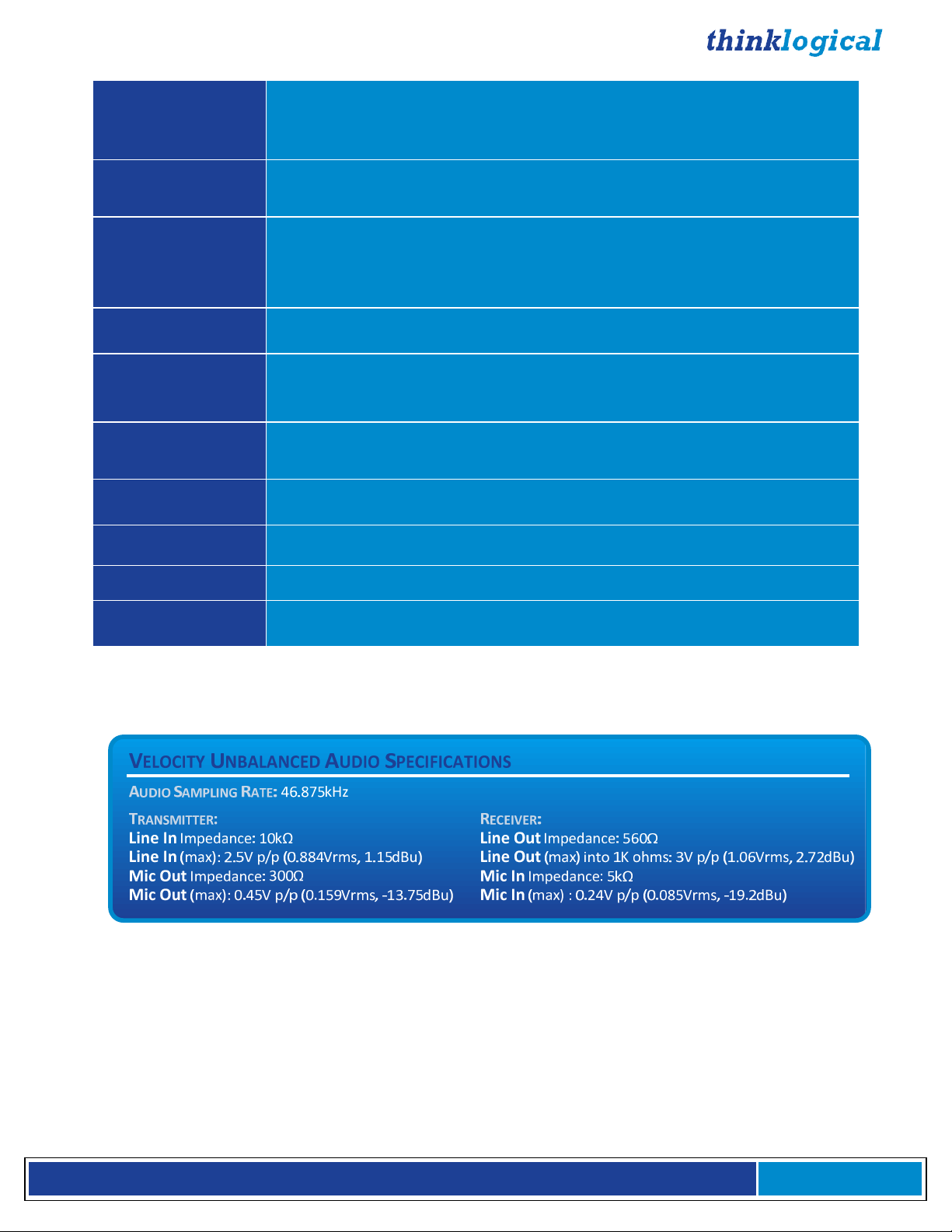
TABLE 2: Velocity Unbalanced Audio Specifications
V e l o c i t y K V M E x t e n d e r P r o d u c t M a n u a l , R e v . B , J a n u a r y , 2 0 1 4 Page 14
Page 15

VelocityKVM-5 Supported RGB Resolutions
Active Resolution
Pixels Lines
640 448 472 66 31.2 25 Honeywell
640 480 525 60 31.5 25.175 Industry Standard
640 480 520 72 37.9 31.5 VESA
640 480 500 75 37.5 31.5 VESA
640 480 509 85 43.3 36 VESA
720 400 449 70 31.5 28.32 Industry Standard
800 600 625 56 35.1 36 VESA
800 600 628 60 37.9 40 VESA
800 600 666 72 48.1 50 VESA
800 600 625 75 46.9 49.5 VESA
800 600 631 85 53.7 56.25 VESA
1024 768 800 50 40 53.44 Folsom
1024 768 806 60 48.4 65 VESA
1024 768 800 75 60 78.75 VESA
1024 768 808 85 68.7 94.5 VESA
1280 720 750 50 37.5 74.25 Folsom
1280 720 750 60 45 74.25 CEA-861-E
1280 800 828 60 49.7 83.46 VESA GTF
1280 1024 1066 50 52.8 89.55 Folsom
1280 1024 1066 60 64 108 VESA
1280 1024 1082 60 64.8 108.88 Discreet
1280 1024 1066 75 80 135 VESA
1280 1024 1072 85 91.1 157.5 VESA
1280 1024 1063 96 102 163.277 SGI Onyx2
1366 768 795 60 47.7 85.5 VESA GTF
1400 1050 1090 50 54.5 94.61 Folsom
1400 1050 1080 60 64.8 120.78 VESA CVT-RB
1400 1050 1089 60 65.3 121.75 VESA
1400 1050 1099 96 105.4 164.5 SGI Stereo
1440 900 932 60 55.8 106.4 VESA GTF
1440 900 934 60 55.9 106.5 VESA DMT
1600 1200 1250 60 75 162 VESA
1680 1050 1089 60 65.3 146.25 VESA DMT
1920 1080 1125 25 28.12 74.25 Folsom
1920 1080 1125 50 56.25 148.5 Folsom
1920 1080 1125 60 67.5 148.5 CEA-861-E
Total
Lines
Vertical
Freq
(Hz)
Horizontal
Freq
(kHz)
Pixel Clock
Freq
(MHz)
Video Standard
TABLE 3: Velocity 5 RGB Resolutions
V e l o c i t y K V M E x t e n d e r P r o d u c t M a n u a l , R e v . B , J a n u a r y , 2 0 1 4 Page 15
Page 16
HARDWARE
Contents
When you receive your Thinklogical VelocityKVM Extender®, you should find the following items:
• VelocityKVM Extender Transmitter
• VelocityKVM Extender Receiver
• AC power cord, PWR-000006-R (International connections may differ) – Qty 2
• VelocityKVM Extender Cables
Video Cable, 2 Meters – See Technical Specs, pg. 13
Audio Cable Kit (8 pcs.), 6 Feet, KIT-000005-R – Qty 1
• VelocityKVM Extender Product Manual CD
• Product Quick Start Guide
All physical connections to the product use industry-standard connectors.
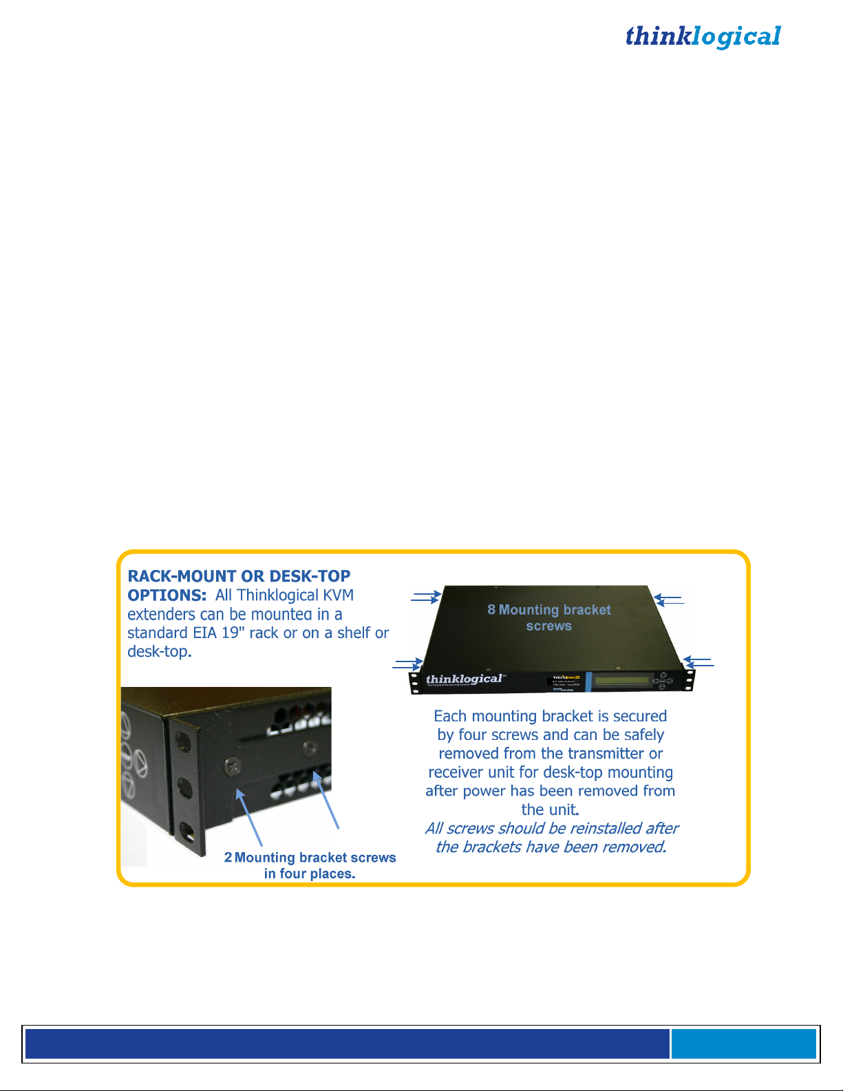
Desktop or Rack Mount Device
You may choose to place your unit on a shelf or desktop (rubber feet included), or rack mount it using
the supplied mounting brackets (EIA 19” rack mountable). The front panel should be visible and
unobstructed so that the front panel buttons and LCD display are accessible. All connections are made
to the rear of the chassis. The VelocityKVM Extender chassis does not need to be opened or accessed.
The sturdy metal case allows units to be stacked as needed.
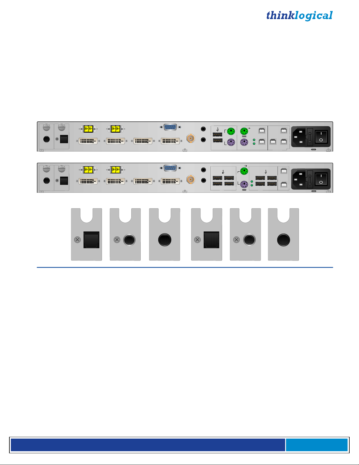
Mounting Bracket Removal
V e l o c i t y K V M E x t e n d e r P r o d u c t M a n u a l , R e v . B , J a n u a r y , 2 0 1 4 Page 16
Page 17
Cooling
The VelocityKVM Extender System uses two DC fans to move air horizontally through the enclosure.
Note: Be sure to leave a minimum of 2” ventilation space on both sides of the units,
especially if the units are being stacked.
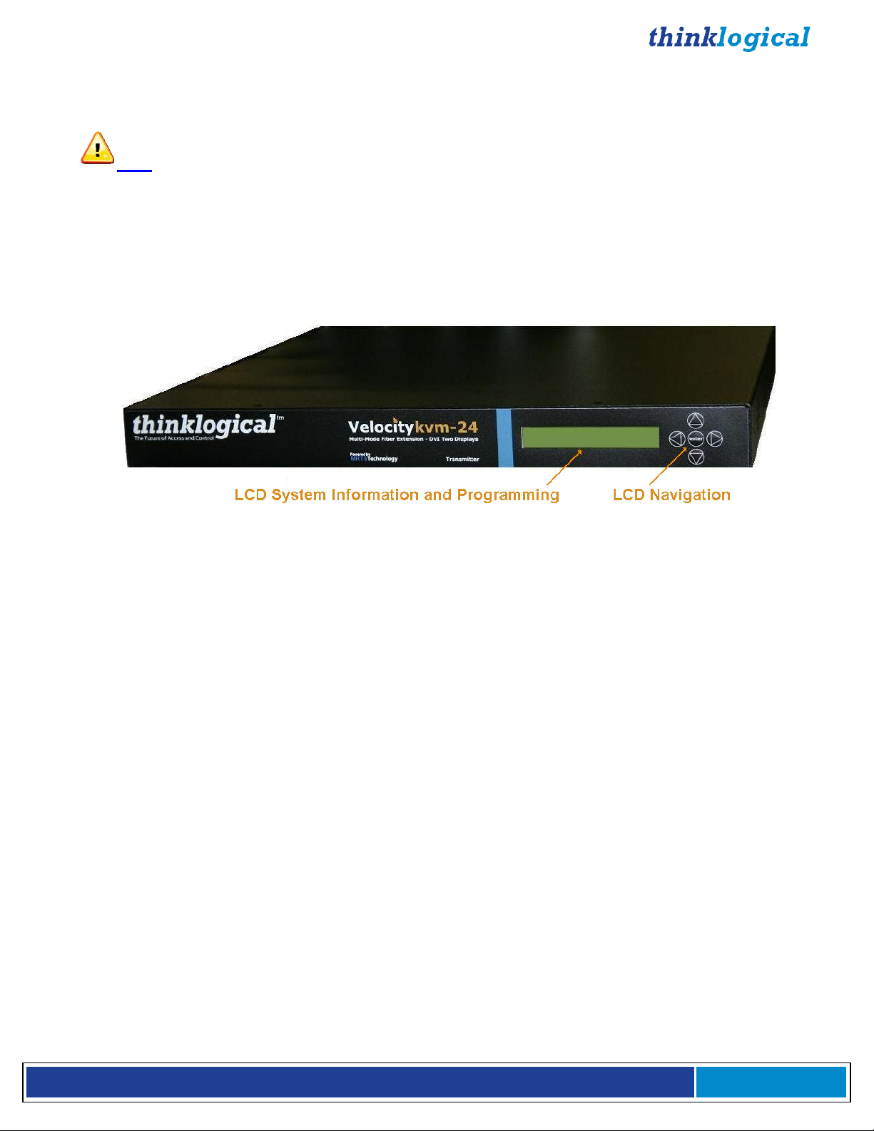
Front Panel Display and Buttons
The front-panel LCD display should be visible and accessible for system setup. The front panel buttons
are used to configure special video settings and to review existing VelocityKVM Extender configurations.
More detailed information on the Front Panel can be found in the General Front Panel Usage section
(Page 27).
VelocityKVM-24 Extender Front Panel LCD Display
Connecting the VelocityKVM Extender
Types of Connections
All physical connections to the product use industry-standard connectors. Non-supplied cables that may
be needed are commercially available. All connections are found on the rear of the unit.
Fiber Cable
Fiber-optic cables run between the Transmitter unit (near your CPU) and the Receiver unit (near your
desktop devices). The standard multi-mode fiber optic cables must be 50 or 62.5µm, terminated with LC,
ST or SC- type fiber optic connectors. Single-mode fiber optic cables must be 9µm, UPC (Ultra Physical
Contact), terminated with LC, ST or SC- type fiber optic connectors. Be careful not to kink or pinch the
fiber optic cable as it is being installed and keep all bend radii to no less than 3 inches (76.2mm).
It is the standard VelocityKVM convention that fiber L1 carries data (PS2, USB, audio, serial, etc.) and
video signal 1 (DVI or RGB) from the transmitter to the receiver. If a back channel is required, fiber L2
carries data from the receiver to the transmitter. If additional video channels are required, they are
carried from transmitter to receiver via fibers L3, L4 and L5, depending on the extender model. (See
page 53 for additional fiber configurations used with the Fail-Over option.)
Transmitter
The transmitter unit connects to the computer at the DVI In port using a DVI-D male-to-male cable
(CBL000009-002MR for single-link and/or CBL000023-002MR for dual-link) which is supplied with the
system. The connections to the VelocityKVM Extender Transmitters can be viewed in detail in the REAR
PANEL VIEW section of this manual beginning on page 19.
Receiver
The receiver unit connects to a video monitor using a DVI-D male-to-male cable. Peripherals connect
with their own standard cables. The connections to the VelocityKVM Extender Receivers can be viewed
in detail in the REAR PANEL VIEW section of this manual.
V e l o c i t y K V M E x t e n d e r P r o d u c t M a n u a l , R e v . B , J a n u a r y , 2 0 1 4 Page 17
Page 18
Receiver Serial Port
The Tx has a DB9F connector and is wired as a DCE (Data Communications Equipment) device.
The Rx has a DB9M connector and is wired as a DTE (Data Terminal Equipment) device. The Tx
connects to the computer and the Rx connects to a touch screen, tablet, tape controller, etc., using a
DB9 Male to DB9 Female Cable (CBL000017-006F is supplied in KIT-000005-R and is provided with the
system). An RS422 option for controlling broadcast equipment is also available.
Stereo Emitter IN
Audio OUT ►
◄Audio IN
USB 2.0
USB HID
PS/2 Keyboard
PS/2 Mouse
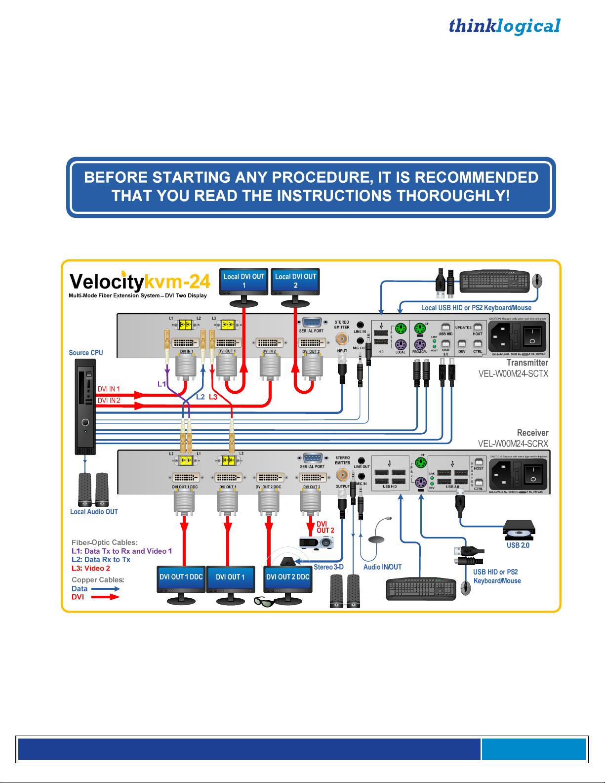
The VelocityKVM-24W (DVI 2 Display, USB-HID, USB 2.0) Fiber Extension System
V e l o c i t y K V M E x t e n d e r P r o d u c t M a n u a l , R e v . B , J a n u a r y , 2 0 1 4 Page 18
Page 19
Rear Panel Views and Hardware Connections
Typically used Fiber and Copper Cables
Fiber Optic Cable (SC)
Fiber Optic Cable (ST)
Fiber Optic Cable (LC)
DVI to DVI
3.5mm AUDIO
A
B
USB (A & B)
Serial (RS232, RS422)
PS2
75Ω BNC
CAT5 (RJ45, Network Option)
VAC
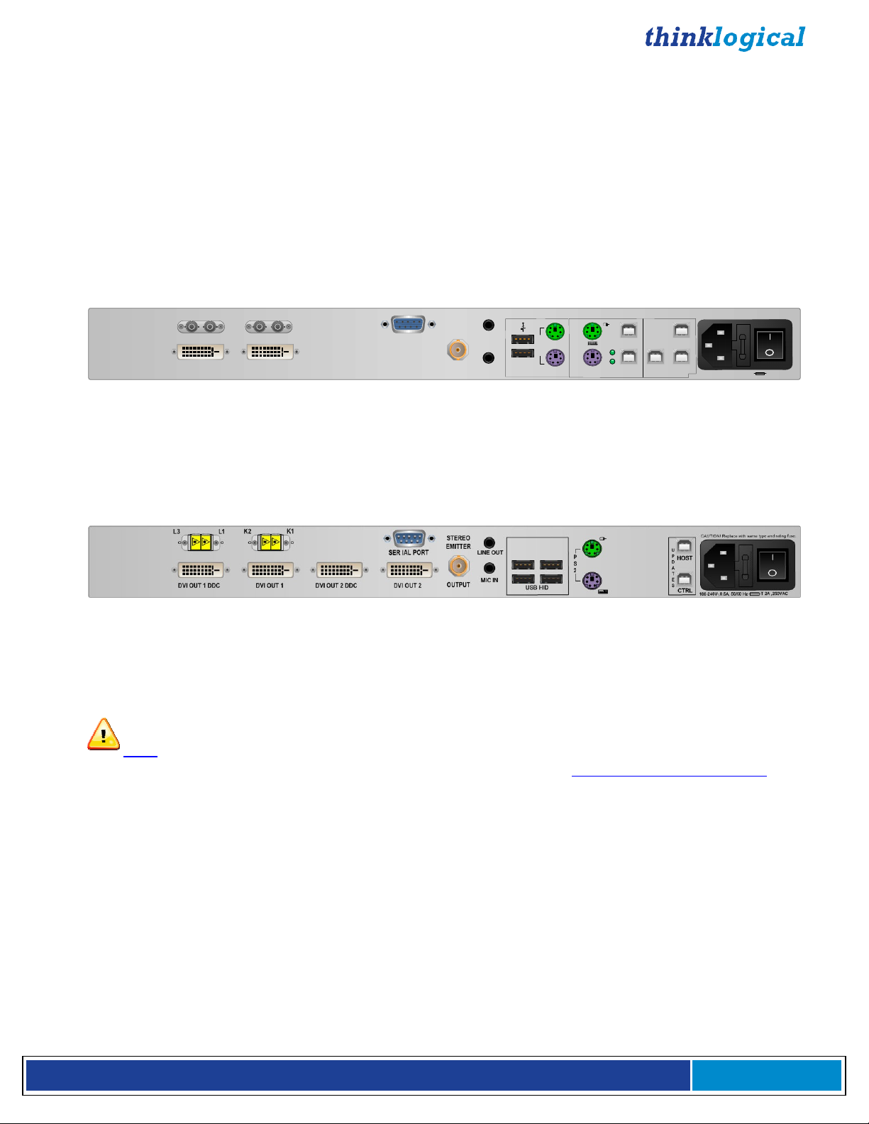
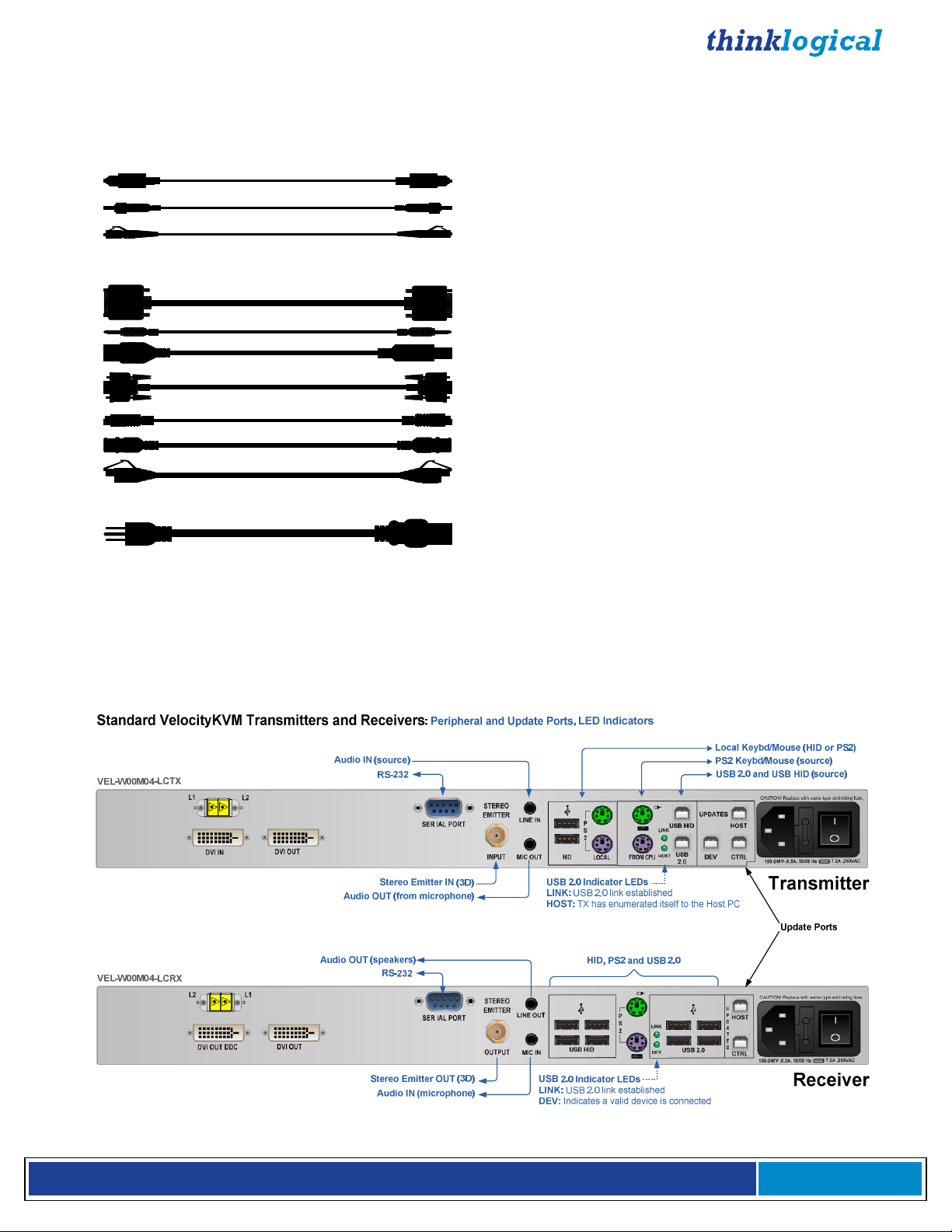
Peripheral and Update Ports
The following Transmitter and Receiver rear panel diagrams denote the functions of the various
peripheral device ports, including the FireWire option and its LED indicators, for all VelocityKVM
Extenders. Refer to the Quick Start Guides in Appendix B for more information.
V e l o c i t y K V M E x t e n d e r P r o d u c t M a n u a l , R e v . B , J a n u a r y , 2 0 1 4 Page 19
Page 20

VelocityKVM Transmitters and Receivers with the FireWire Option: Peripheral and Update Ports, LED Indicators
NOTE: The FireWire option requires 2 additional Fiber Optic Cables.
Audio IN (source)
FireWire (Fibers & IN Port)
FireWire Indicator LEDs
PWR: FireWire PCB power On/Off
CP: ON=Cable Powered
CLINK: ON=CPU connected (linked)
FOL: (Fiber Optic Link) ON=connection, BLINKING=no connection
Unmarked LEDs are non-functioning
Audio OUT (speakers)
FireWire (Fibers & OUT Port)
FireWire Indicator LEDs
PWR: FireWire PCB power On/Off
CP: ON=Cable Powered
CLINK: ON=CPU connected (linked)
FOL: (Fiber Optic Link) ON=connection, BLINKING=no connection
Unmarked LEDs are non-functioning
RS-232
Stereo Emitter IN (3D)
Audio OUT
(from microphone)
RS-232
USB HID & USB 2.0 IN
USB HID, PS2 and USB 2.0
Audio IN (microphone)
Stereo Emitter OUT (3D)
Local Keyboard/Mouse (HID or PS2)
PS2 Keyboard/Mouse (source)
Transmitter
VEL-F00M04-LCTX
Update Ports
Receiver
VEL-F00M04-LCRX
Fiber and Video Ports
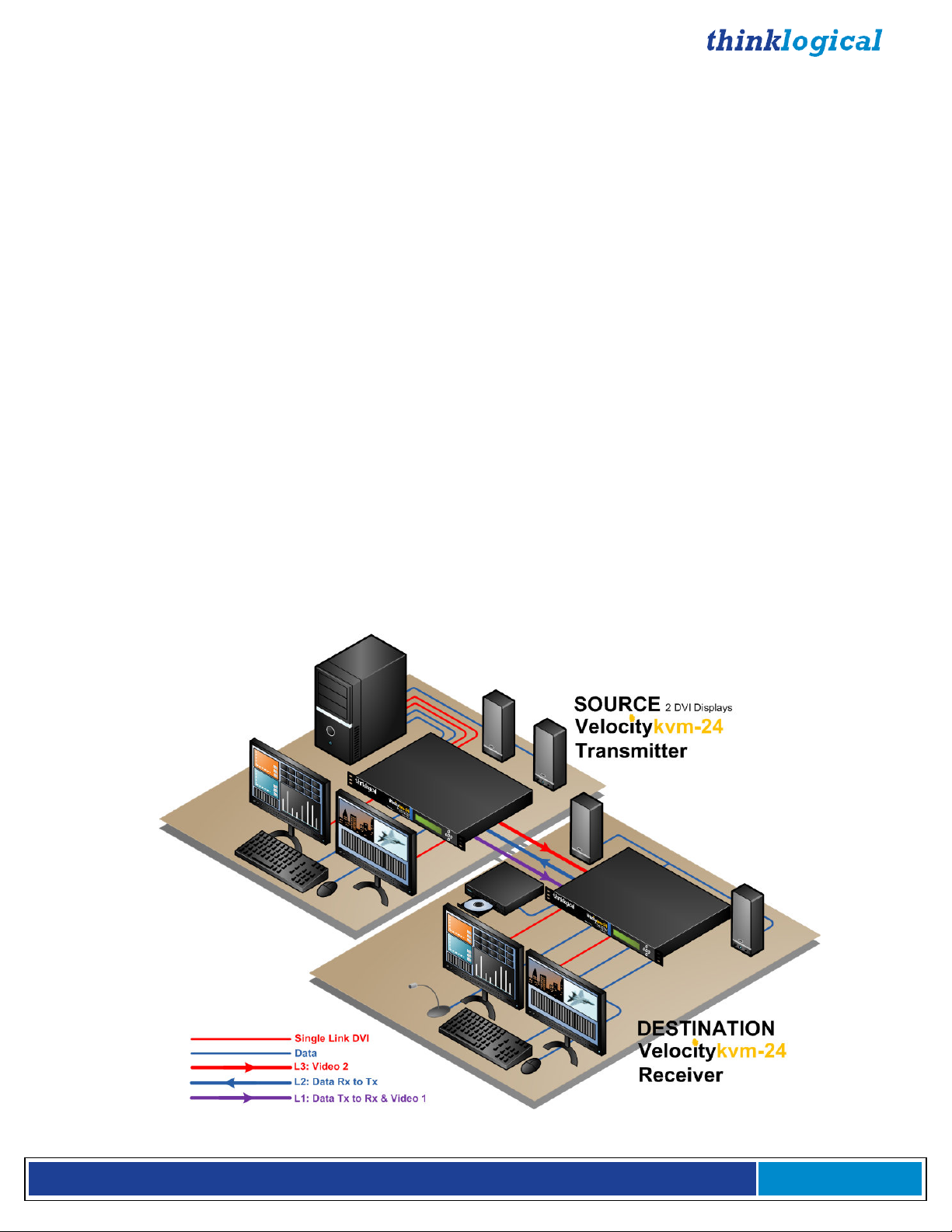
The following transmitter and receiver rear panel diagrams explain the functions of the fiber optic cable
input and output ports and the video input and output ports for each of the VelocityKVM Extenders. For
the fiber connections, Optical Fiber L1, which carries both DATA from Tx to Rx and VIDEO, is in
purple, Optical Fiber L2, which carries DATA from Rx to Tx, is in blue and all VIDEO ONLY fibers
are in red. Refer to the Quick Start Guides in Appendix B (pg. 45-52) for more information.
V e l o c i t y K V M E x t e n d e r P r o d u c t M a n u a l , R e v . B , J a n u a r y , 2 0 1 4 Page 20
Page 21

Velocity-5 KVM Multi-Mode Extender
Single-Head, Single-Link RGB/DVI
Transmitter
VEL-W00M05-LCTX
Receiver
VEL-W00M05-LCRX
L1 Fiber: Data Tx to Rx & Video
L2 Fiber: Data Rx to Tx
RGB/DVI OUT (local)
RGB/DVI IN (from source)
L2 Fiber: Data Rx to Tx
L1 Fiber: Data Tx to Rx & Video
Velocity-8 KVM Multi-Mode Extender
Dual-Link DVI
Transmitter
VEL-W00M08-LCTX
Receiver
VEL-W00M08-LCRX
RGB/DVI OUT (Secondary)
RGB/DVI OUT (DDC)
L1 Fiber: Data Tx to Rx & Video Primary
L2 Fiber: Data Rx to Tx
L3 Fiber: Video Secondary
Dual-Link DVI OUT (local)
Dual-Link DVI IN (from source)
L2 Fiber: Data Rx to Tx
L1 Fiber: Data Tx to Rx & Video Primary
L3 Fiber: Video Secondary
Dual-Link DVI OUT (Secondary)
Dual-Link DVI OUT (DDC)
V e l o c i t y K V M E x t e n d e r P r o d u c t M a n u a l , R e v . B , J a n u a r y , 2 0 1 4 Page 21
Page 22

Velocity-24 KVM Multi-Mode Extender
DVI 2 Display
Transmitter
VEL-W00M24-LCTX
Receiver
VEL-W00M24-LCRX
Velocity-28 KVM Multi-Mode Extender
Dual-Link, Single-Link DVI, 2 Display
Transmitter
VEL-W00M28-LCTX
L1 Fiber: Data Tx to Rx & Video 1
L2 Fiber: Data Rx to Tx
L3 Fiber: Video 2
L2 Fiber: Data Rx to Tx
L1 Fiber: Data Tx to Rx & Video 1
L3 Fiber: Video 2
L1 Fiber: Data Tx to Rx & Video 1 Primary
L2 Fiber: Data Rx to Tx
L3 Fiber: Video 1 Secondary
L4 Fiber: Video 2
DVI OUT 2 (local)
DVI IN 2 (from source)
DVI OUT 1 (local)
DVI IN 1 (from source)
DVI OUT 2 (Secondary)
DVI OUT 2 (DDC)
DVI OUT 1 (Secondary)
DVI OUT 1 (DDC)
Single-Link DVI OUT 2 (local)
Single-Link DVI IN 2 (from source)
Dual-Link DVI OUT 1 (local)
Dual-Link DVI IN 1 (from source)
L2 Fiber: Data Rx to Tx
L1 Fiber: Data Tx to Rx & Video 1 Primary
L4 Fiber: Video 2
Receiver
VEL-W00M28-LCRX
L3 Fiber: Video 1 Secondary
Single-Link DVI OUT 2
Dual-Link DVI OUT 1
V e l o c i t y K V M E x t e n d e r P r o d u c t M a n u a l , R e v . B , J a n u a r y , 2 0 1 4 Page 22
Page 23

V e l o c i t y K V M E x t e n d e r P r o d u c t M a n u a l , R e v . B , J a n u a r y , 2 0 1 4 Page 23
Page 24

Velocity-38 KVM Multi-Mode Extender
2 Dual-Link DVI Displays
Transmitter
VEL-W00M38-LCTX
Receiver
VEL-W00M38-LCRX
L1 Fiber: Data Tx to Rx & Video 1 Primary
L2 Fiber: Data Rx to Tx
L3 Fiber: Video 1 Secondary
L4 Fiber: Video 2 Primary
L5 Fiber: Video 2 Secondary
Dual-Link DVI OUT 2 (local)
Dual-Link DVI IN 2 (from source)
Dual-Link DVI OUT 1 (local)
Dual-Link DVI IN 1 (from source)
L2 Fiber: Data Rx to Tx
L1 Fiber: Data Tx to Rx & Video 1 Primary
L4 Fiber: Video 2 Primary
L3 Fiber: Video 1 Secondary
L5 Fiber: Video 2 Secondary
Dual-Link DVI OUT 2
Dual-Link DVI OUT 1
Cables
Peripheral Cables:
KIT-000005-R Audio Cable Kit (8 pcs.)– Qty 1, all models
2 each – USB A-B (6’)
2 each – 3.5mm to 3.5mm plug (6’)
1 each – DB9M to DB9F (6’)
1 each – BNC male to male, 75Ω (6’)
2 each – 6 pin mini din (6’)
KIT-5 Cables (Included)
V e l o c i t y K V M E x t e n d e r P r o d u c t M a n u a l , R e v . B , J a n u a r y , 2 0 1 4 Page 24
Page 25

Video Cables
Depending on the VelocityKVM Extender model, use the following video cables:
Single-link: DVI-D Male Cable, 2 Meters (CBL000009-002MR)
Single-link: DVI-I Male Cable, 2 Meters (CBL000013-002MR)
RGB: HD15 to DVI-A Male Cable, 2 Meters (CBL000022-002MR) - VelocityKVM-5, Qty 1
Dual-link: DVI-D Male Cable, 2 Meters (CBL000023-002MR)
V e l o c i t y K V M E x t e n d e r P r o d u c t M a n u a l , R e v . B , J a n u a r y , 2 0 1 4 Page 25
Page 26

Installation
All physical connections to the product use industry-standard connectors. Non-supplied cables are
commercially available. All connections are found on the rear of the unit. Refer to the Quick Start
Guides in Appendix B (pg. 45-52) for more information.
Set-Up
Firmware Upgrades
Firmware upgrades are available through Thinklogical. Please call for assistance: 1-203-647-8700.
Front Panel Usage
V e l o c i t y K V M E x t e n d e r P r o d u c t M a n u a l , R e v . B , J a n u a r y , 2 0 1 4 Page 26
Page 27

General Front Panel Usage
*System
Thinkl
ogical
Once the system is powered up, the initial Transmitter display is shown as follows:
Velocity Tx VXX.XX
The company name is listed on the first line of the display. The model and software version (VXX.XX) of
the unit is displayed on the second line.
By pressing the down arrow the VelocityKVM Extender allows you to enter into the main menu.
The main root menu items are displayed with an *. They are as follows:
*DDC
Once a *root menu item is displayed, you can then use the left arrow or right arrow to review
settings or make changes, if allowed.
SFP LOS and SFP Des OK Signal
In the *System root menu, scrolling right or left will bring you to the SFP Loss of Signal and SFP Des
OK Signal menus.
The SFP Loss of Signal menu provides confirmation of lost or unused video signals at the Receiver
and of lost or unused data-return signals at the Transmitter. A lost/unused signal will be indicated by a
1 at SFPs 1 through 4 on a Receiver and by a 1 at SFP 1 on a Transmitter. If only 2 SFPs are in use, as
in a VelocityKVM-24 Receiver, SFPs 3 and 4 will always indicate that no signal is present (1).
The SFP Des OK Signal menu provides confirmation that a good deserializer signal is detected at the
Receiver and Transmitter SFPs. A good signal will be indicated by a 1 at SFPs 1 through 4. If only 2
SFPs are in use, as in a VelocityKVM-24, SFPs 3 and 4 will always indicate that no signal is present (1).
Fiber L1 on the Transmitter and L2 on the Receiver are always transmitting. The SFPs connected to
fibers L3, L4 and L5 will not transmit until a video signal is applied to the Transmitter’s DVI IN connector.
V e l o c i t y K V M E x t e n d e r P r o d u c t M a n u a l , R e v . B , J a n u a r y , 2 0 1 4 Page 27
Page 28

The following table shows the expected SFP Loss of Signal and Des OK Signal indications for each
model of a properly connected VelocityKVM Receiver and Transmitter:
TABLE 4: SFP Loss Of Signal and SFP Des OK Signal LCD Indicators
V e l o c i t y K V M E x t e n d e r P r o d u c t M a n u a l , R e v . B , J a n u a r y , 2 0 1 4 Page 28
Page 29

The VelocityKVM Extender menu functionality is as follows
(Some menu options may not be available on all models.):
TRANSMITTER:
Display Modifiable Description
*System
LS Connected NO Indicates fiber status from TX to RX. (0=connected)
Tx Ctrl Name TX Only Name entered on TX unit is displayed on RX unit.
Load Defaults YES Loads factory default video configurations.
Store Values YES Store video configurations.
KM Device NO Revision of the VelocityKVM portion that plugs into CPU.
KM Remote Host NO Revision of the VelocityVKM Host on the RX unit.
KM Local Host NO Revision of the VelocityVKM Host on the TX unit.
TX Control NO Revision of the TX unit laser and front panel control.
RX Control NO Revision of the RX unit laser and front panel control.
FPGA Version NO Revision of the FPGA used for video generation.
Serial Number NO 2 digits: week, 2 digits: year, 2 to 4 digits unique unit number
Debug Values YES Factory Use.
Allow FPGA Update YES Select YES to enable update
Aud/USB Reset En YES Enable/disable USB 1.1 reset, lost Tx/Rx link
Des OK NO 1=Yes 0=No
SFP Loss of Signal NO Indicates loss of SFP signal. (1= not connected)
Temp in Celsius NO Tb=PCB temp (max=70) Tf=FPGA temp (max=85)
KMASS Card ID NO 0E = original, OC=SoDimm
Video Card ID NO 08=single 09=dual head 0A=dual link 0B=RGB
USB 2.0 Card ID NO 08=original 09=SoDimm
*DDC
DDC PROM Emula. Mode YES Options are Dynamic, Static and Passthru.
In Dynamic mode, the EDID table* of the monitor connected to the
RX is read and stored on the TX. After any change in monitor type
a new EDID table will be stored on the TX. An EDID table is always
presented to the video source, whether the TX is ON or OFF.
Static mode is used to maintain the current EDID table regardless
of monitor changes at the RX. An EDID table is always presented to
the video source, whether the TX is ON or OFF.
Passthru mode makes the DDC pins look like direct connection
between the TX and RX, allowing the computer to talk directly to
the monitor.
Load Default DDC YES Loads the default EDID table* into the TX which allows 1024x768
and 1920x1200. This puts the TX into static mode.
Load 1080p YES Loads a widescreen version of the EDID table* into the TX.
Supported resolutions include 1920x1080 and 1280x720.
Acquire DDC YES Gets the EDID table* of the attached display, stores the information
on the TX, and puts the TX in static mode.
Force DDC Mode YES Used to force a monitor to appear as either digital or analog.
Since the Velocity products can convert between analog and
digital, sometimes the EDID table* has to be modified to match the
method of connecting the TX to CPU.
*See EDID Definitions and DDC Modes in Appendix F, page 60
V e l o c i t y K V M E x t e n d e r P r o d u c t M a n u a l , R e v . B , J a n u a r y , 2 0 1 4 Page 29
Page 30

Velocity 5 Video Front Panel Menu
TRANSMITTER
Display Modifiable Description
* Video
VGA Connected NO An indication of whether VGA video is input to the Vis TX
Resolution input NO Active pixels x active lines vertical rate
Hor. Freq NO Horizontal frequency
Auto Phase YES Automatically adjusts the Sampling Phase to the best setting
PLL Total YES Total pixels, one line. (Horiz. active pixels + Horiz. blanking pixels)
HSOUT Width YES Horizontal sync (Hsync) of video, measured in pixels
DE Start YES Horizontal back porch (Hpb) of video, measured in pixels
DE Width YES Total active pixels in one line
Line Start YES Vertical back porch (Vbp) + Vertical sync (Vsync) of video,
measured in lines
Line Width YES The number of visible lines in one frame
Hsync Period NO Used to determine analog video horizontal frequency.
Use the following formula to calculate the frequency:
(25x10E6 x 16) / Hsync Period = Horizontal Frequency
Vsync Period NO Total lines in one frame of video = active lines + blanking lines
ISL Sync Status NO Thinklogical support use only. Measures sync selection and ………
sync polarity
ISL Sync Activity NO Thinklogical support use only. Measures sync activity
Video 1 cnt. NO Thinklogical support use only. Video IN pixel clock (in hex)
___________________________________________________________________________
RECEIVER:
*System
LS Connected NO Indicates fiber status from TX to RX (0=connected)
Tx Ctrl Name TX Only Name entered on TX unit is displayed on RX unit.
KM Device NO Revision of the VelocityKVM portion that plugs into CPU.
KM Remote Host NO Revision of the VelocityVKM Host on the RX unit.
KM Local Host NO Revision of the VelocityVKM Host on the TX unit.
TX Control NO Revision of the TX unit laser and front panel control.
RX Control NO Revision of the RX unit laser and front panel control.
FPGA Version NO Revision of the FPGA used for video generation.
Serial Number NO 2 digits: week, 2 digits: year, 2 to 4 digits unique unit number
Debug Values YES Factory Use.
Allow FPGA Update YES Select YES to enable update
SFP Loss of Signal NO Indicates loss of SFP signal. (1=not connected)
SFP Des OK Signal NO 1=Yes 0=No
LS FPGA Ver. NO LS Data communication FPGA
Vid1. FPGA Rev. NO Video FPGA for Head 1
Vid1. FPGA Type NO Video FPGA for Head 2
Temp in Celsius NO Tb=PCB temp (max=70) Tf=FPGA temp (max=85)
KMASS Card ID NO 0E=original, OA= SoDimm
KMASS FPGA Rev. NO FPGA used for LS/USB 2.0 Card
KMASS Device ID NO Hardware ID of KMASS Card
Video Card ID NO Hardware ID of Video Card
V e l o c i t y K V M E x t e n d e r P r o d u c t M a n u a l , R e v . B , J a n u a r y , 2 0 1 4 Page 30
Page 31

Display Modifiable Description
Aux. Card ID NO Hardware ID of Auxiliary Card
Aux. Card FPGA Rev. NO FPGA Rev. of Auxiliary Card
Original KMASS YES Option to use previous Interface revisions
Allow Out Of Band YES Allows On-screen Display when used with Routers*
Alt. HOT Key YES Used to modify Out Of Band Hot Key
*Contact Thinklogical before using this feature as it may impact the fiber channel.
*DDC
DDC PROM Emula. Mode YES Options are Dynamic, Static and Passthru.
In Dynamic mode, the EDID table* of the monitor connected to the
RX is read and stored on the TX. After any change in monitor type
a new EDID table will be stored on the TX. An EDID table is always
presented to the video source, whether the TX is ON or OFF.
Static mode is used to maintain the current EDID table regardless
of monitor changes at the RX. An EDID table is always presented to
the video source, whether the TX is ON or OFF.
Passthru mode makes the DDC pins look like direct connection
between the TX and RX, allowing the computer to talk directly to
the monitor.
Load Default DDC YES Loads the default EDID table* into the TX which allows 1024x768
and 1920x1200. This puts the TX into static mode.
Load 1080p YES Loads a widescreen version of the EDID table* into the TX.
Supported resolutions include 1920x1080 and 1280x720.
Acquire DDC YES Gets the EDID table* of the attached display, stores the information
on the TX, and puts the TX in static mode.
Force DDC Mode YES Used to force a monitor to appear as either digital or analog.
Since the Velocity products can convert between analog and
digital, sometimes the EDID table* has to be modified to match the
method of connecting the TX to CPU.
*Video
VGA Connected NO An indication of whether VGA video is input to the Vis TX
Resolution NO Active pixels x active lines vertical rate
Hor. Freq NO Horizontal frequency
Auto Phase YES Automatically adjust the Sampling Phase to the best setting
PLL Total YES Total pixels, one line. (Horiz. active pixels + Horiz. blanking pixels)
HSOut Width YES Horizontal sync (Hsync) of video, measured in pixels
DE Start YES Horizontal back porch (Hpb) of video, measured in pixels
DE Width YES Total active pixels in one line
Line Start YES Vert. back porch (Vbp) + Vert. sync (Vsync) measured in lines
Line Width YES The number of visible lines
Hsync Period NO Used to determine analog video horizontal frequency.
Use the following formula to calculate the frequency:
(25x10E6 x 16) / Hsync Period = Horizontal Frequency
Vsync Period NO Total lines in one video frame = active lines + blanking lines
ISL Sync Status NO Thinklogical support use only. Measures sync selection & polarity
ISL Sync Activity NO Thinklogical support use only. Measures sync activity
Video RX 1 cnt. NO Thinklogical support use only. Video IN 1 pixel clock (in hex)
*See EDID Definitions and DDC Modes in Appendix F, page 60
V e l o c i t y K V M E x t e n d e r P r o d u c t M a n u a l , R e v . B , J a n u a r y , 2 0 1 4 Page 31
Page 32

Thinkl
ogical
Store Values
Thinkl
ogical
Store Values
Saving Changes
Save analog video configurations so that following power up, the device can recall
custom video settings.
Velocity Tx VXX.XX
Using the down arrow, scroll down to *System as shown below.
*System
Using the right arrow, scroll right until Store Values is displayed as shown below, then press enter.
Yes/No.= No
Using the up arrow or down arrow scroll until Yes appears as shown below. Then press enter.
Yes/No.= Yes
Using the right arrow or left arrow scroll until you return to the *System menu option. Using up arrow or
down arrow, scroll until you get to the Thinklogical screen as shown below.
Velocity Tx VXX.XX
V e l o c i t y K V M E x t e n d e r P r o d u c t M a n u a l , R e v . B , J a n u a r y , 2 0 1 4 Page 32
Page 33

Restoring Factory Defaults
Thinkl
ogical
*System
Load Defaults
Load Defaults
Load the factory default video configurations.
Velocity Tx VXX.XX
Using the down arrow, scroll down to *System (below).
Using the right arrow button, scroll right until Load Defaults is displayed (below), then press enter.
Yes/No= No
Using the up arrow or down arrow, scroll until Yes appears (below), then press enter.
Yes/No= Yes
Follow the steps below to save your changes:
Using the down arrow, scroll down to *System.
Using the right arrow, scroll right until Store Values is displayed, then press enter.
Using the up or down arrow, scroll until Yes appears, then press enter.
Using the right or left arrow, scroll to return to the *System menu option.
Using up or down arrow, scroll until you get to the Thinklogical screen.
V e l o c i t y K V M E x t e n d e r P r o d u c t M a n u a l , R e v . B , J a n u a r y , 2 0 1 4 Page 33
Page 34

Naming the Transmitter Unit
Thinkl
ogical
*System
Tx Ctrl
TX Ctrl
Tx Ctrl
Modify the name of the unit through the Transmitter. The name entered on the
Transmitter will display on the Receiver unit.
Using the arrow down button, scroll down to *System as shown below.
Velocity Tx VXX.XX
Using the right arrow, scroll right until Tx Ctrl is displayed (below), then press enter.
Name= TxUnit01
Using the right or left arrow, scroll until the blinking cursor is under the letter/number you want to change.
Name= TxUnit01
Using the up or down arrow, scroll (holding down the up or down arrow will scroll faster) until you find the
appropriate letter/number, then press enter.
Name= TxUnit11
V e l o c i t y K V M E x t e n d e r P r o d u c t M a n u a l , R e v . B , J a n u a r y , 2 0 1 4 Page 34
Page 35

*System
Using the right or left arrow, scroll to return to the *System menu option.
Follow these steps to save your changes:
Using the down arrow, scroll down to *System.
Using the right arrow, scroll right until Store Values is displayed, then press enter.
Using the up or down arrow, scroll until Yes appears, then press enter.
Using the right or left arrow, scroll to return to the *System menu option.
Using up or down arrow, scroll until you get to the Thinklogical screen.
Regulatory & Safety Compliance
Safety Requirements
Symbols Found on Our Product
Markings and labels on the product follow industry-standard conventions. Regulatory markings found on
the products comply with domestic and many international requirements.
Regulatory Compliance
The Thinklogical VelocityKVM Extender® products are designed and made in the U.S.A. VelocityKVM
Extender® products have been tested by a certified testing laboratory and found to be compliant with the
following standards (both domestic USA and many international locations):
North America
Safety
ANSI/UL60950-1: 1st Edition (2003)
CAN/CSA C22.2 No. 60950-1-03
LASER Safety
CDRH 21CFR 1040.10
Class 1 LASER Product
Electromagnetic Interference
FCC CFR47, Part 15, Class A
Industry Canada ICES-003 Issue 2, Revision 1
V e l o c i t y K V M E x t e n d e r P r o d u c t M a n u a l , R e v . B , J a n u a r y , 2 0 1 4 Page 35
Page 36

Australia & New Zealand
This is a Class A product. In a domestic environment this product may cause radio interference, in
which case the user may be required to take adequate measures.
European Union
Declaration of Conformity
Manufacturer’s Name & Address: Thinklogical
®
LLC
100 Washington Street
Milford, Connecticut 06460 USA
Telephone 1-203-647-8700
These products comply with the requirements of the Low Voltage Directive 72/23/EEC and the EMC
Directive 89/336/EEC.
Standards with Which Our Products Comply
Safety
CENELEC EN 60950-1, 1st Edition (2001)
LASER Safety
IEC60825:2001 Parts 1 and 2
Class 1 LASER Product
Electromagnetic Emissions
EN55022: 1994 (IEC/CSPIR22: 1993)
EN61000-3-2/A14: 2000
EN61000-3-3: 1994
Electromagnetic Immunity
EN55024: 1998 Information Technology Equipment-Immunity Characteristics
EN61000-4-2: 1995 Electro-Static Discharge Test
EN61000-4-3: 1996 Radiated Immunity Field Test
EN61000-4-4: 1995 Electrical Fast Transient Test
EN61000-4-5: 1995 Power Supply Surge Test
EN61000-4-6: 1996 Conducted Immunity Test
EN61000-4-8: 1993 Magnetic Field Test
EN61000-4-11: 1994 Voltage Dips & Interrupts Test
Supplementary Information
The following statements may be appropriate for certain geographical regions and might not apply to
your location.
V e l o c i t y K V M E x t e n d e r P r o d u c t M a n u a l , R e v . B , J a n u a r y , 2 0 1 4 Page 36
Page 37

This Class A digital apparatus meets all requirements of the Canadian Interference-Causing
Equipment Regulations.
Cet appareil numérique de la classe A respecte toutes les exigencies du Règlement sur le matérial
brouilleur du Canada.
Warning! This is a Class A product. In a domestic environment, this product may cause
radio interference, in which case the user may be required to take corrective measures.
Note: This equipment has been tested and found to comply with the limits for a Class A
digital device, pursuant to part 15 of the FCC Rules. These limits are designed to provide
reasonable protection against harmful interference when the equipment is operated in a
commercial environment. This equipment generates, uses and can radiate radio frequency
energy and, if not installed and used in accordance with the instruction manual, may cause
harmful interference to radio communications in which case the user may be required to take
adequate corrective measures at their own expense.
Note: This Class A digital apparatus complies with Canadian ICES-003 and has been
verified as being compliant within the Class A limits of the FCC Radio Frequency Device Rules
(FCC Title 47, Part 15, Subpart B CLASS A), measured to CISPR 22: 1993 limits and methods of
measurement of Radio Disturbance Characteristics of Information Technology Equipment.
Note:
magnetic fields
Note:
may be needed to comply with Immunity Requirements
The user may notice degraded audio performance in the presence of electro-
.
If using a keyboard that is noise susceptible, a ferrite ring on the keyboard cable
Product Serial Number
Thinklogical® products have a unique serial number printed on an adhesive label that is fixed, typically,
to the underside of the unit. The serial number includes a date-code formatted as 2 digits for the week
and 2 digits for the year, plus two to four digits for a unique unit number.
Example: Serial number 2813124 indicates that the unit was built in the 28th week of the year 2013 and
is unit number 124.
Connection to Our Products
Connections and installation hardware for our products use industry-standard devices and methods. All
wiring connections to the customer equipment are designed to minimize proprietary or customized
connectors and cabling. Power connections are made with regionally appropriate power cords and
approved methods.
V e l o c i t y K V M E x t e n d e r P r o d u c t M a n u a l , R e v . B , J a n u a r y , 2 0 1 4 Page 37
Page 38

How to Contact Us
Customer Support
Thinklogical is an engineering company and you will receive the assistance you require directly from our
most knowledgeable engineers. We believe that the first line of support is the design engineer that
developed each particular product. Therefore your needs will be handled promptly by our in-house
engineers who are most familiar with your products.
Website
Check out our website for current product offerings, support information and general information about
all of the products we offer.
Our internet website offers product information on all current systems, including technical specification
sheets and installation guides (for viewing online or for download), product diagrams showing physical
connections and other information you might need.
Internet: www.thinklogical.com
Note: Most online documents are stored as Adobe Acrobat “PDF” files. If you do not have
the Adobe Acrobat reader needed to view PDF files, visit www.adobe.com for a download.
Email
Thinklogical is staffed Monday through Friday from 8:30am to 5:00pm, Eastern Time Zone. We will do
our best to respond to your emails promptly. Please use one of the following email addresses for your
particular needs:
info@thinklogical.com – Information on Thinklogical and our products.
sales@thinklogical.com – Sales Department - orders, questions or issues.
support@thinklogical.com – Product support, technical issues or questions, product
repairs and request for Return Authorization.
Telephone
Product & Customer Support: 1-203-647-8700
US Commercial & Canada Sales: 1-203-647-8769
US Federal Government Sales: 1-203-647-8716
Toll Free in the Continental US: 1-800-291-3211
International Sales (Europe, Middle East, Africa): 1-203-647-8704
International Sales (Asia Pacific, Central & Latin America): 1-203-647-8734
Fax: 1-203-783-9949
V e l o c i t y K V M E x t e n d e r P r o d u c t M a n u a l , R e v . B , J a n u a r y , 2 0 1 4 Page 38
Page 39

Please contact our expert sales staff in Milford, CT. We are here Monday through Friday from
8:30am to 5:00pm, Eastern Time Zone. We’ll provide a representative’s direct dial phone
number when you call.
If leaving a voice message, please provide a preferred time to call back so we may reach you at
your convenience.
Our switchboard attendant will direct your call during regular business hours. We have an
automated attendant answering our main telephone switchboard after regular business hours
and holidays. You can leave voice messages for individuals at any time.
Fax
Our company facsimile number is 1-203-783-9949. Please indicate the nature of the fax on your
cover sheet and provide return contact information.
Product Support
Thinklogical’s support personnel are available Monday through Friday from 8:30am to 5:00pm,
Eastern Time Zone. If your application requires assistance at some time outside of our normal business
hours, please contact us beforehand and we will do our best to make arrangements to help you with your
Thinklogical products.
Limited Warranty Information
Thinklogical, LLC (“Thinklogical”) warrants this product against defects in materials and workmanship for
a period of one (1) year from the date of delivery (ordinary wear and tear excluded). This limited warranty
does not cover defects resulting from (i) use of the product other than as described in the applicable
documentation for the product; (ii) modifications to or repairs of the product that are made by any party
other than Thinklogical or a party acting on Thinklogical’s behalf, or (iii) combination of the product with
third party products that is not consented to by Thinklogical. Occurrences of events described in (i) – (iii)
shall void the foregoing warranty. This warranty gives you specific legal rights, and you may also have
other rights which vary from state to state.
Except for the express warranty set forth above, to the fullest extent permitted under applicable
law, Thinklogical, LLC and its suppliers disclaim any and all other warranties, express and
implied, including without limitation the implied warranties of merchantability, fitness for a
particular purpose, title and non-infringement.
If the defective product is returned to the authorized dealer within one (1) year of the delivery date, repair
or replacement of the product will be made. Repairs may be made with refurbished parts. If repair or
replacement is not possible, Thinklogical may keep the defective product and refund the amount that you
paid for the defective product. These are Thinklogical’s sole obligations, and your exclusive remedies, for
a breach of the limited warranty set forth above.
To return a defective product, contact the Thinklogical authorized dealer from whom you purchased the
product. Do not return a product directly to Thinklogical without prior authorization from your dealer.
If you have received prior authorization from your dealer and are returning a product directly to
Thinklogical:
1. You may contact your Sales Representative directly or call Customer Support at 1-203-647-8700
or 1-800-291-3211 (toll free).
2. Describe the defect with the product and Customer Support will issue a Return Merchandise
Authorization Number (RMA#).
3. Pack the product in all of its original packing, if possible, and write the RMA number on the box.
4. Return the product to: Thinklogical, LLC
Attn: RMA# [Insert the issued RMA# here.]
100 Washington Street
Milford, CT 06460 USA
V e l o c i t y K V M E x t e n d e r P r o d u c t M a n u a l , R e v . B , J a n u a r y , 2 0 1 4 Page 39
Page 40

If you have any issue with a product, have product questions or need technical assistance with your
Thinklogical system, please call us at 1-800-291-3211 (USA only) or 1-203-647-8700 and let us help.
V e l o c i t y K V M E x t e n d e r P r o d u c t M a n u a l , R e v . B , J a n u a r y , 2 0 1 4 Page 40
Page 41

Appendix A
In the following part number examples, the inclusion of the USB 2.0 option is shown. (This is the U
immediately following the VEL-). If no option is included, the U will be replaced by a 0. For the FireWire
option, this will be an F and for the HID option, it will be a leading H. See page 44 for more information
on part numbering.
Thinklogical's Full Line of Velocitykvm and Video Multi-Mode Fiber
Extenders
Part Number
VEL-W00M04-LCRX
VEL-W00M04-LCTX
VEL-W00M04-SCRX
VEL-W00M04-SCTX
VEL-W00M04-STRX
VEL-W00M04-STTX
VEL-W00M05-LCRX
VEL-W00M05-LCTX
VEL-W00M05-SCRX
VEL-W00M05-SCTX
VEL-W00M05-STRX
Description
VelocityKVM-4 Multi-Mode Fiber Extenders
Velocity KVM Extender Receiver, Single Head Single Link DVI, USB 2.0, KMAS, Multi-mode, LC
Velocity KVM Extender Transmitter, Single Head Single Link DVI, USB 2.0, KMAS, Multi-mode, LC
Velocity KVM Extender Receiver, Single Head Single Link DVI, USB 2.0, KMAS, Multi-mode, SC
Velocity KVM Extender Transmitter, Single Head Single Link DVI, USB 2.0, KMAS, Multi-mode, SC
Velocity KVM Extender Receiver, Single Head Single Link DVI, USB 2.0, KMAS, Multi-mode, ST
Velocity KVM Extender Transmitter, Single Head Single Link DVI, USB 2.0, KMAS, Multi-mode, ST
VelocityKVM-5 Multi-Mode Fiber Extenders
Velocity KVM Extender Rx, Single Head Dual Link DVI/RGB, USB 2.0, KMAS, Multi-mode, LC
Velocity KVM Extender Tx, Single Head Dual Link DVI/RGB, USB2.0, KMAS, Multi-mode, LC
Velocity KVM Extender Rx, Single Head Dual Link DVI/RGB, USB 2.0, KMAS, Multi-mode, SC
Velocity KVM Extender Tx, Single Head Dual Link DVI/RGB, USB2.0, KMAS, Multi-mode, SC
Velocity KVM Extender Rx, Single Head Dual Link DVI/RGB, USB 2.0, KMAS, Multi-mode, ST
VEL-W00M05-STTX
VEL-W00M08-LCRX
VEL-W00M08-LCTX
VEL-W00M08-SCRX
VEL-W00M08-SCTX
VEL-W00M08-STRX
VEL-W00M08-STTX
V e l o c i t y K V M E x t e n d e r P r o d u c t M a n u a l , R e v . B , J a n u a r y , 2 0 1 4 Page 41
Velocity KVM Extender Tx, Single Head Dual Link DVI/RGB, USB2.0, KMAS, Multi-mode, ST
VelocityKVM-8 Multi-Mode Fiber Extenders
Velocity KVM Extender Receiver, Single Head Dual Link DVI, USB 2.0, KMAS, Multi-mode, LC
Velocity KVM Extender Transmitter, Single Head Dual Link DVI, USB 2.0, KMAS, Multi-mode, LC
Velocity KVM Extender Receiver, Single Head Dual Link DVI, USB 2.0, KMAS, Multi-mode, SC
Velocity KVM Extender Transmitter, Single Head Dual Link DVI, USB 2.0, KMAS, Multi-mode, SC
Velocity KVM Extender Receiver, Single Head Dual Link DVI, USB 2.0, KMAS, Multi-mode, ST
Velocity KVM Extender Transmitter, Single Head Dual Link DVI, USB 2.0, KMAS, Multi-mode, ST
Page 42

Part Number
VelocityKVM-24 Multi-Mode Fiber Extenders
VEL-W00M24-LCRX
VEL-W00M24-LCTX
VEL-W00M24-SCRX
VEL-W00M24-SCTX
VEL-W00M24-STRX
VEL-W00M24-STTX
VEL-W00M28-LCRX
VEL-W00M28-LCTX
VEL-W00M28-SCRX
VEL-W00M28-SCTX
VEL-W00M28-STRX
VEL-W00M28-STTX
VEL-W00M34-LCRX
Velocity KVM Extender Receiver, Dual Head Single Link DVI, USB 2.0, KMAS, Multi-mode, LC
Velocity KVM Extender Transmitter, Dual Head Single Link DVI, USB 2.0, KMAS, Multi-mode, LC
Velocity KVM Extender Receiver, Dual Head Single Link DVI, USB 2.0, KMAS, Multi-mode, SC
Velocity KVM Extender Transmitter, Dual Head Single Link DVI, USB 2.0, KMAS, Multi-mode, SC
Velocity KVM Extender Receiver, Dual Head Single Link DVI, USB 2.0, KMAS, Multi-mode, ST
Velocity KVM Extender Transmitter, Dual Head Single Link DVI, USB 2.0, KMAS, Multi-mode, ST
VelocityKVM-28 Multi-Mode Fiber Extenders
Velocity KVM Extender Receiver, Dual Link, Single Link DVI, USB 2.0, KMAS, Multi-mode, LC
Velocity KVM Extender Transmitter, Dual Link, Single Link DVI, USB 2.0, KMAS, Multi-mode, LC
Velocity KVM Extender Receiver, Dual Link, Single Link DVI, USB 2.0, KMAS, Multi-mode, SC
Velocity KVM Extender Transmitter, Dual Link, Single Link DVI, USB 2.0, KMAS, Multi-mode, SC
Velocity KVM Extender Receiver, Dual Link, Single Link DVI, USB 2.0, KMAS, Multi-mode, ST
Velocity KVM Extender Transmitter, Dual Link, Single Link DVI, USB 2.0, KMAS, Multi-mode, ST
VelocityKVM-34 Multi-Mode Fiber Extenders
Velocity KVM Extender Receiver, DVI Four Display, USB 2.0, KMAS, Multi-mode, LC
VEL-W00M34-LCTX
VEL-W00M34-SCRX
VEL-W00M34-SCTX
VEL-W00M34-STRX
VEL-W00M34-STTX
VEL-W00M35-LCRX
VEL-W00M35-LCTX
VEL-W00M35-SCRX
VEL-W00M35-SCTX
VEL-W00M35-STRX
VEL-W00M35-STTX
VEL-W00M38-LCRX
VEL-W00M38-LCTX
Velocity KVM Extender Transmitter, DVI Four Display, USB 2.0, KMAS, Multi-mode, LC
Velocity KVM Extender Receiver, DVI Four Display, USB 2.0, KMAS, Multi-mode, SC
Velocity KVM Extender Transmitter, DVI Four Display, USB 2.0, KMAS, Multi-mode, SC
Velocity KVM Extender Receiver, DVI Four Display, USB 2.0, KMAS, Multi-mode, ST
Velocity KVM Extender Transmitter, DVI Four Display, USB 2.0, KMAS, Multi-mode, ST
VelocityKVM-35 Multi-Mode Fiber Extenders
Velocity KVM Extender Receiver, DVI Three Display, USB 2.0, KMAS, Multi-mode, LC
Velocity KVM Extender Transmitter, DVI Three Display, USB 2.0, KMAS, Multi-mode, LC
Velocity KVM Extender Receiver, DVI Three Display, USB 2.0, KMAS, Multi-mode, SC
Velocity KVM Extender Transmitter, DVI Three Display, USB 2.0, KMAS, Multi-mode, SC
Velocity KVM Extender Receiver, DVI Three Display, USB 2.0, KMAS, Multi-mode, ST
Velocity KVM Extender Transmitter, DVI Three Display, USB 2.0, KMAS, Multi-mode, ST
VelocityKVM-38 Multi-Mode Fiber Extenders
Velocity KVM Extender Receiver, DVI two Dual-link Display, USB 2.0, KMAS, Multi-mode, LC
Velocity KVM Extender Transmitter, DVI two Dual-link Display, USB 2.0, KMAS, Multi-mode, LC
VEL-W00M38-SCRX
VEL-W00M38-SCTX
VEL-W00M38-STRX
VEL-W00M38-STTX
V e l o c i t y K V M E x t e n d e r P r o d u c t M a n u a l , R e v . B , J a n u a r y , 2 0 1 4 Page 42
Velocity KVM Extender Receiver, DVI two Dual-link Display, USB 2.0, KMAS, Multi-mode, SC
Velocity KVM Extender Transmitter, DVI two Dual-link Display, USB 2.0, KMAS, Multi-mode, SC
Velocity KVM Extender Receiver, DVI two Dual-link Display, USB 2.0, KMAS, Multi-mode, ST
Velocity KVM Extender Transmitter, DVI two Dual-link Display, USB 2.0, KMAS, Multi-mode, ST
Page 43

Thinklogical's Full Line of Velocitykvm and Video Single-Mode Fiber
Extenders
Part Number
VEL-W00S04-SCRX
VEL-W00S04-SCTX
VEL-W00S05-SCRX
VEL-W00S05-SCTX
VEL-W00S08-SCRX
VEL-W00S08-SCTX
VEL-W00S24-SCRX
VelocityKVM-4 Single-Mode Fiber Extenders
Velocity KVM Extender Rx, Single Head Single Link DVI, USB 2.0, KMAS, Single-mode, SC/APC
Velocity KVM Extender Tx, Single Head Single Link DVI, USB 2.0, KMAS, Single-mode, SC/APC
VelocityKVM-5 Single-Mode Fiber Extenders
Velocity KVM Extender Rx, Single Head Dual Link DVI/RGB, USB 2.0, KMAS, Single-mode, SC/APC
Velocity KVM Extender Tx, Single Head Dual Link DVI/RGB, USB2.0, KMAS, Single-mode, SC/APC
VelocityKVM-8 Single-Mode Fiber Extenders
Velocity KVM Extender Rx, Single Head Dual Link DVI, USB 2.0, KMAS, Single-mode, SC/APC
Velocity KVM Extender Tx, Single Head Dual Link DVI, USB 2.0, KMAS, Single-mode, SC/APC
VelocityKVM-24 Single-Mode Fiber Extenders
Velocity KVM Extender Rx, Dual Head Single Link DVI, USB 2.0, KMAS, Single-mode, SC/APC
Description
VEL-W00S24-SCTX
Part Number
VEL-W00S28-SCRX
VEL-W00S28-SCTX
VEL-W00S34-SCRX
VEL-W00S34-SCTX
VEL-W00S35-SCRX
VEL-W00S35-SCTX
VEL-W00S38-SCRX
VEL-W00S38-SCTX
Velocity KVM Extender Tx, Dual Head Single Link DVI, USB 2.0, KMAS, Single-mode, SC/APC
VelocityKVM-28 Single-Mode Fiber Extenders
Velocity KVM Extender Rx, Dual Link, Single Link DVI, USB 2.0, KMAS, Single-mode, SC/APC
Velocity KVM Extender Tx, Dual Link, Single Link DVI, USB 2.0, KMAS, Single-mode, SC/APC
Velocity KVM-34 Single-Mode Fiber Extenders
Velocity KVM Extender Rx, 4 Display DVI, USB 2.0, KMAS, Single-mode, SC/APC
Velocity KVM Extender Tx, 4 Display DVI, USB 2.0, KMAS, Single-mode, SC/APC
VelocityKVM-35 Single-Mode Fiber Extenders
Velocity KVM Extender Rx, 3 Display DVI, USB 2.0, KMAS, Single-mode, SC/APC
Velocity KVM Extender Tx, 3 Display DVI, USB 2.0, KMAS, Single-mode, SC/APC
VelocityKVM-38 Single-Mode Fiber Extenders
Velocity KVM Extender Rx, Two Dual-link DVI Display, USB 2.0, KMAS, Single-mode, SC/APC
Velocity KVM Extender Tx, Two Dual-link DVI Display, USB 2.0, KMAS, Single-mode, SC/APC
V e l o c i t y K V M E x t e n d e r P r o d u c t M a n u a l , R e v . B , J a n u a r y , 2 0 1 4 Page 43
Page 44

VEL-XXXXXX-XXXX
VEL= Velocity
VEA = Velocity with
Separate Audio
Part Number Reference
Velocity KVM
Extenders
000= USB 1.1
00D= USB 1.1 with Separate Data Path
0R0= USB 1.1 with Redundant Fiber Path
0RD= USB 1.1 with Redundant Fiber Path and Separate Data Path
A00= Professional Audio, HID, No USB 1.1 or USB 2.0
A0D= Professional Audio, HID, No USB 1.1 or USB 2.0 with Separate Data Path
AR0= Professional Audio, HID, No USB 1.1 or USB 2.0, Redundant Fiber Path
ARD= Professional Audio, HID, No USB 1.1 or USB 2.0, Redundant, Separate Data Path
E00= Firewire with USB 2.0, No USB 1.1
E0D= Firewire with USB 2.0 with Separate Data Path, No USB 1.1
F00= Firewire with USB 1.1H00= HID
HOD= HID with Separate Data Path
HR0= HID, Redundant
HRD= HID, Redundant, Separate Data Path
K00= Network with USB 2.0, HID
K0D= Network with USB 2.0, HID, Separate Data Path
KR0= Network with USB 2.0, HID, Redundant Fiber Path
KRD= Network with USB 2.0, HID, Separate Data Path, Redundant Fiber Path
N00= Network, USB 1.1
N0D= Network with Separate Data Path, USB 1.1, HID
P00= Professional Audio, HID with USB 2.0, no USB 1.1
P0D= Professional Audio, HID with USB 2.0, no USB 1.1, Separate Data Path
PR0= Professional Audio, HID with USB 2.0, no USB 1.1, Redundant Fiber Path
PRD= Professional Audio, HID with USB 2.0, no USB 1.1, Redundant, Separate Data Path
U00= USB 2.0
U0D= USB 2.0 with Separate Data Path
UR0= USB 2.0 with Redundant Fiber Path
W00= HID with USB 2.0, No USB 1.1
WR0= HID with USB 2.0 with Redundant Fiber Path, No USB 1.1
W0D= HID with USB 2.0 with Separate Data Path, No USB 1.1
WRD= HID with USB 2.0 with Redundant Fiber Path and Separate Data Path, No USB 1.1
W00= Multipath, HID with USB 2.0, No USB 1.1
W0D= Multipath, HID with USB 2.0 with Separate Data Path, No USB 1.1
WRD= Multipath, HID with USB 2.0 with Redundant Fiber Path and Separate Data Path, No USB 1.1
Z00= Multipath, Professional Audio, HID with USB 2.0, No USB 1.1
ZR0= Multipath, Professional Audio, HID with USB 2.0 with Redundant Fiber Path, No USB 1.1
Z0D= Multipath, Professional Audio, HID with USB 2.0 with Separate Data Path, No USB 1.1
ZRD= Multipath, Professional Audio, HID with USB 2.0 with Redundant Fiber Path and Separate Data Path, No USB 1.1
TX= Transmitter
RX= Receiver
ST Connector
SC Connector
LC Connector
NK Connector
03= 1 SL DVI
06= 1 DL DVI
09= 1 RGB
10= 1 RGB/DVI
12= 1 RGB HV, Component Video
M= Multi-Mode
S= Single-Mode
X= Multi-Path
V e l o c i t y K V M E x t e n d e r P r o d u c t M a n u a l , R e v . B , J a n u a r y , 2 0 1 4 Page 44
Page 45

Appendix B- Quick Start Guides
A.B.1 VelocityKVM-4 Quick Start Guide
V e l o c i t y K V M E x t e n d e r P r o d u c t M a n u a l , R e v . B , J a n u a r y , 2 0 1 4 Page 45
Page 46

V e l o c i t y K V M E x t e n d e r P r o d u c t M a n u a l , R e v . B , J a n u a r y , 2 0 1 4
STEP 5: If desired, connect your optional
local keyboard & mouse by inserting the PS/2
Velocitykvm-5
Velocitykvm-5
Multi-Mode Fiber Extension System – Single Head, Single Link RGB/DVI
Multi-Mode Fiber Extension System – Single Head, Single Link RGB/DVI
QUICK START GUIDE
QUICK START GUIDE
Local RGB
5
OUT
/DVI
or USB HID connectors into the VelocityKVM
Transmitter’s local devices receptacles and
connect the optional local RGB/DVI display to
the Transmitter’s RGB/DVI OUT Port. Ensure
all system functions are operating properly.
USB HID or PS2
Keyboard/Mouse
5
A.B.2 VelocityKVM-5 Quick Start Guide
Source CP
Local
Audio
OUT
U
STEP 1: Connect your Multi-Mode Fiber
Optic Cables between the Transmitter and
Receiver units (up to 1000 meters) as shown.
1
N
RGB/DVI I
4
L1: Data Tx to Rx and Video
L2: Data Rx to Tx
Stere
Stereo Emitter IN
3-
D
o
◄
Audio I
N
Audio OUT ►
PS/2 Keyboard
PS/2
Mouse
USB HID (
USB HID or PS2
Keyboard/Mouse
USB 2.0
ybd/Mouse
K
)
STEP 2: Ensure that
the POWER ON/OFF
switch is in the OFF
position (0) on both
the Tx and Rx units.
Connect the supplied
AC Power Cords to
both units and plug
each into a standard
AC supply. Turn both
switches ON (1).
USB 2.0
2
3
OUT
DDC
GB/DVI OU
R
T
Audio IN/OU
T
STEP 3: Connect the destination RGB/DVI and KVM
devices to the VelocityKVM Receiver using RGB/
DVI cables and standard copper cables. Ensure the
devices are turned ON.
RGB/DVI
VELOCITY-5W_Manual_QSG_Rev_A
Page 46
Page 47

A.B.3 VelocityKVM-8 Quick Start Guide
V e l o c i t y K V M E x t e n d e r P r o d u c t M a n u a l , R e v . B , J a n u a r y , 2 0 1 4 Page 47
Page 48

A.B.4 VelocityKVM-24 Quick Start Guide
V e l o c i t y K V M E x t e n d e r P r o d u c t M a n u a l , R e v . B , J a n u a r y , 2 0 1 4 Page 48
Page 49

A.B.5 VelocityKVM-28 Quick Start Guide
V e l o c i t y K V M E x t e n d e r P r o d u c t M a n u a l , R e v . B , J a n u a r y , 2 0 1 4 Page 49
Page 50

USB 2.0
USB HID (Kybd/Mouse)
PS/2 Keyboard
PS/2 Mouse
Audio OUT ►
◄ Audio IN
Stereo Emitter IN
A.B.6 VelocityKVM-34 Quick Start Guide
V e l o c i t y K V M E x t e n d e r P r o d u c t M a n u a l , R e v . B , J a n u a r y , 2 0 1 4 Page 50
Page 51

V e l o c i t y K V M E x t e n d e r P r o d u c t M a n u a l , R e v . B , J a n u a r y , 2 0 1 4
Velocitykvm-35
Velocitykvm-35
Multi-Mode Fiber Extension System – Three DVI Displays
Multi-Mode Fiber Extension System – Three DVI Displays
QUICK START GUIDE
QUICK START GUIDE
5
USB HID or PS2 Keyboard/Mouse
A.B.7 VelocityKVM-35 Quick Start Guide
Fiber-Optic Cables:
L1: Data Tx to Rx and Video 1
Source CP
L2: Data Rx to Tx
U
L3: Video 2
L4: Video 3
Local Audio OUT
STEP 1: Connect the 4 Multi-Mode Fiber-Optic Cables
between the Transmitter and Receiver units (up to 1000
meters) as shown.
STEP 2: *
STEP 3: Connect the destination DVI and KVM devices to
the Ve locityKVM Receiver u sing standard cables. Ensure
the devices are turned ON.
STEP 4: Connect the DVI and KVM cables between the
Source CPU and the VelocityKVM Transmitter using the
cables supplied in KIT-000005-R. Ensure the CPU i s turned
ON.
STEP 5: If desired, connect your optional local keyboard &
mouse by inserting the PS/2 or USB HID connectors into the
VelocityKVM Transmitter’s local devices receptacles.
Ensure all system functions are operating properly.
Page 51
D
V
VI IN 2
D
DVI IN
I IN
1
3
eo Emitter IN
Ste
r
14
D
Stereo 3-
UT
DVI O
1
DVI O
UT
2
DVI O
UT
Audio
◄IN
Audio OUT ►
PS/2 Keyboard
use
PS/2 Mo
USB HID
3
USB 2.0
(Kybd/Mouse)
3
Audio IN/OU
USB HID or PS2 Keyboard/Mouse
T
*STEP 2: Ensure that
the POWER ON/OFF
switch is in the OFF
position (0) on both the
Tx and Rx units.
Connect the supplied
AC Power Cords to
both units and plug
each into a standard
AC supply. Turn both
switches ON (1).
2
USB 2.0
Velocity-35W_Manual_QSG_ Rev_A
Page 52

A.B.8 VelocityKVM-38 Quick Start Guide
V e l o c i t y K V M E x t e n d e r P r o d u c t M a n u a l , R e v . B , J a n u a r y , 2 0 1 4 Page 52
Page 53

Appendix C- Automatic Fail-Over Option
For applications in need of an Auto Fail-Over system, Thinklogical offers a solution to meet this need in
each of our VelocityKVM models. This option features two separate fiber paths for each signal and the
ability to select which of the two paths is the viable path.
The Transmitter and Receiver contain all the same features as the standard VelocityKVM products in
addition to offering a redundant fiber connector (L1’, L2’, etc.) for each standard fiber connector (L1, L2,
etc.). All other features function as in our standard VelocityKVM Extenders.
Example:
VelocityKVM-24WR Transmitter with Automatic Fail-Over
Fiber Connections
L1 and L1' are redundant outputs, transmitting the same video and KMASS data; L3 and L3' are
redundant outputs, transmitting the same video data. The same will apply to any additional video fibers
(L4, L4’, L5, L5’, etc.) used in other models.
L2 and L2' are redundant back channel KMASS data inputs. There is an internal MUX which selects L2
or L2' data. When the unit is powered on, it will select L2 first (if L2 is active); otherwise, it will select L2'
(if L2' is active). It will only switch from L2 to L2' if L2 is inactive and L2' is active. Likewise, it will only
switch from L2' to L2 if L2' is inactive and L2 is active.
VelocityKVM-24WR Transmitter (VEL-WR0M24-LCTX)
VelocityKVM-24WR Receiver with Automatic Fail-Over
Fiber Connections
L1 and L1' are redundant video and KMASS data inputs. There is an internal MUX which selects L1 or
L1'. When the unit is powered on, it will select L1 first (if L1 is active); otherwise, it will select L1' (if L1' is
active). It will only switch from L1 to L1' if L1 is inactive and L1' is active. Likewise, it will only switch from
L1' to L1 if L1' is inactive and L1 is active.
L2 and L2' are redundant outputs, transmitting the same KMASS data.
L3 and L3' are redundant video data inputs. There is an internal MUX which selects L3 or L3'. When the
unit is powered on, it will select L3 first (if L3 is active); otherwise, it will select L3' (if L3' is active). It will
only switch from L3 to L3' if L3 is inactive and L3' is active. Likewise, it will only switch from L3' to L3 if
L3' is inactive and L3 is active. The same will apply to any additional video fibers used in other models.
VelocityKVM-24WR Receiver (VEL-WR0M24-LCRX)
V e l o c i t y K V M E x t e n d e r P r o d u c t M a n u a l , R e v . B , J a n u a r y , 2 0 1 4 Page 53
Page 54

Typical VelocityKVM-24WR and VX160 System with Automatic Fail-Over
V e l o c i t y K V M E x t e n d e r P r o d u c t M a n u a l , R e v . B , J a n u a r y , 2 0 1 4 Page 54
Page 55

Appendix D- Keyboard/Mouse/Audio Control Options
Selectable KMASS/Separate KMASS
Original:
All KMASS data (keyboard, mouse, audio, etc.) sent from the TX unit is on fiber L1 along with the video
data.
User RX unit receives all KMASS data on fiber L1 along with video data.
Standard (Selectable KMASS):
The Tx unit is the same as above.
The RX unit can receive KMASS DATA on L1, L3, L4 and L5 along with video data. The RX unit will
select one input. Input selection is controlled by the TX unit‘s L2 back channel status. If the TX unit is
receiving valid data on L2 it will send KMASS data on its L1 fiber and a status signal indicating that it has
a good back channel connection. Note that Audio is always sent on L1.
The RX unit detects valid back channel status from the TX unit and will use KMASS data from the TX
unit with a valid back channel. If multiple valid back channels are received, L1 has the highest priority,
then L3, etc.
When no Tx has a valid back channel, L1 is used and audio will still function.
Original (Additional forward KMASS):
Same as above: Selectable KMASS with the addition of a forward KMASS fiber (K1) on TX and RX unit.
K1 transfers KMASS data only, not video data. The additional fiber required for K1 can be elimated if you
use a BIDI optical option. K1 and L2 can be combined on one fiber at different wavelengths. Note that L2
can also be refered to as K2 on some units.
At the RX unit, K1 has priority over L1, L3, L4 and L5, but if the RX unit is not receiving data on K1 it will
then use L1, etc. for KMASS.
L2 works the same for all unit types. L2 transfers the KMASS data from the RX unit to the TX unit.
Forward KMASS only:
Same as above: Additional forward KMASS, except for the TX unit L1 output. L1 will only output video
data. Note that all TX units only output KMASS data on L1 and K1, not L3, L4, or L5.
Conclusion:
Above are the present KMASS options. Other KMASS options can also be possible along with
redundancy options.
Selectable KMASS HID, USB 2.0 and Control Options
HID:
Velocity HID will still function with only one connection from the RX unit to the TX unit (L2). It is also
possible to control multiple CPU's from one RX unit if the L2 back channel is connected to the TX units
and HID is used. The mouse may be erratic, but will still function. Note that L2 should only be connected
from one RX unit to one TX unit. A broadcast connection of L2 to multiple units is incorrect and should
never be done.
USB 2.0
USB 2.0 will only control one CPU at a time. It requires a full duplex connection to function, typically L1
and L2. So if L2 is broadcast to multiple TX units, USB 2.0 will only control one CPU. The CPU controlled
by USB 2.0 may be different depending on what type of Velocity or T-Series extender you are using.
V e l o c i t y K V M E x t e n d e r P r o d u c t M a n u a l , R e v . B , J a n u a r y , 2 0 1 4 Page 55
Page 56

Appendix E-
VelocityKVM Extender Series: Separate Data Paths,
Separate Audio Paths and Multi-Path Video Options
Thinklogical’s® line of Separate Data Path, Separate Audio Path and Multi-Path Video
Options are designed to accommodate systems that require data transmission security and for
systems with a lower video transmission rate, or for systems not transmitting video through a
Thinklogical® KVM Matrix Switch.
®
• The VelocityKVM Separate Data
Path Extender allows KMASS data
to be transmitted on one fiber and
received on another fiber, separate
from video data, which is transmitted
on a separate, third fiber.
• The VelocityKVM Separate Audio
Path Extender allows audio signals
to be transmitted on one fiber and
received on another fiber, separate
from Video, USB, PS2, RS-232 and
Stereo Emitter data, which are
transmitted on two independent fibers
• The VelocityKVM Multi Video Path
Extender allows one 6.22 Gbps DVI signal
to be transmitted across two fibers at a
bandwidth of 3.11 Gbps per fiber.
Each of our Separate Data & Audio Path and Multi-Path Video VelocityKVM line of
extenders is available with the full complement of options regularly available with all of
our VelocityKVM extenders, such as RJ45 Network ports and various combinations of
USB HID, USB 2.0 and FireWire ports.
On the following pages are examples of the various options available with each of these
VelocityKVM Extender models.
V e l o c i t y K V M E x t e n d e r P r o d u c t M a n u a l , R e v . B , J a n u a r y , 2 0 1 4 Page 56
Page 57

Separate Data Paths Option:
Separate Data Paths
Transmitter
(top) and Receiver
VelocityKVM-24K Extender Transmitter (VEL-W0DM24-LCTX) & Receiver (VEL-W0DM24-LCRX):
DVI 2 Display, USB HID, USB 2.0, RS-232 Serial, Stereo Emitter, Audio, Separate Data Paths (Allows
KMASS data to be transmitted on one fiber and received on another fiber, separate from video data,
which is transmitted on a separate, third fiber).
Unlike standard VelocityKVM Extenders, where data and video are transmitted together from Tx to Rx on
fiber L1 and back-channel data is transmitted from Rx to Tx on a fiber designated as L2, the Separate
Data Path Option keeps video on fiber L1 while data is transmitted from Tx to Rx on a separate fiber
designated as K1. The back-channel data is transmitted from Rx to Tx on fiber K2, allowing for greater
workstation security and system control.
V e l o c i t y K V M E x t e n d e r P r o d u c t M a n u a l , R e v . B , J a n u a r y , 2 0 1 4 Page 57
Separate Data Paths Tx to Rx Application
Page 58

Separate Audio Paths Option:
VelocityKVM-24WA Extender Transmitter
DVI 2 Display, USB HID, USB 2.0, RS-232 Serial, Stereo Emitter, Audio, Separate Audio Paths (Allows
audio data to be transmitted on one fiber and received on another fiber, separate from Video, USB, PS2,
RS-232 and Stereo data, which are transmitted on two independent fibers).
The Separate Audio Path Option allows audio signals in and audio signals out to be kept on two
independent fibers designated as A1 and A2, allowing for greater workstation security and system
control. USB, PS2, stereo emitter and serial data remain on fibers L1 and L2 as in standard VelocityKVM
models.
Transmitter (top) and Receiver
(VEA-W00M24-LCTX)
& Receiver
(VEA-W00M24-LCRX):
CPU/Rack Mount
Operating System
router
MX48
KVM Matrix Switch
3 Rack Units
200 Watts
SOURCE
VelocityKVM-4WA
1 DVI Display, Separate
Audio Extender Tx
Network Hub
S
k
r
o
W
o
T
o
S
m
o
r
F
Audio
i
t
a
t
c
r
u
Local
OUT
Separate
Audio
Out
T
-
4
R
2
x
0
C
0
h
a
s
s
i
s
n
o
L
1
:
L
S
2
y
:
s
S
A
e
1
P
C
Local
DVI OUT
t
y
e
s
m
t
&
A
U
e
D
m
a
2
:
S
t
D
a
a
T
t
a
e
p
a
T
x
x
R
t
o
x
r
a
t
e
T
-
4
C
h
R
t
o
x
T
A
x
u
d
i
o
I
n
&
O
2
0
0
a
s
s
i
s
Work Station
VelocityKVM-4WA
.
.
.
.
.
.
1 DVI Display, Separate
Audio Extender Rx
Separate Audio IN
&
V
i
d
e
o
U
T
4 Fiber Optic Cables per Chassis
L1: System Data Tx to Rx & Video
L2: System Data Rx to Tx
A1: Separate Audio Tx to Rx
A2: Separate Audio Rx to Tx
Copper Cables
DVI Video
System Data
Separate Audio
CAT5
Separate Audio Paths Tx to Rx Application
V e l o c i t y K V M E x t e n d e r P r o d u c t M a n u a l , R e v . B , J a n u a r y , 2 0 1 4 Page 58
Page 59

Multi-Path Video Option:
VelocityKVM-4WX Extender Transmitter
DVI 1 Display, USB HID, USB 2.0, RS-232 Serial, Stereo Emitter, Audio, Multi-Path Video (Allows one
6.22 Gbps DVI signal to be transmitted across two fibers at a bandwidth of 3.11 Gbps per fiber).
Thinklogical’s VX line of KVM Matrix Switch Routers, unlike other routers on the market, supports each
6.25 Gbps bandwidth video connection from our Velocity line of extender products. When a Thinklogical
router is not part of your system, the Multi-Path Video option allows two 3.11 Gbps bandwidth video
signals to transmit through a 4 Gbps router for increased system flexibility and control.
Transmitter (top) and Receiver
(VEL-W00X04-LCTX)
& Receiver
(VEL-W00X04-LCRX):
Multi-Path Video Tx to Rx Application using a 4 Gbps router
V e l o c i t y K V M E x t e n d e r P r o d u c t M a n u a l , R e v . B , J a n u a r y , 2 0 1 4 Page 59
Page 60

Appendix F: EDID Definition and DDC Modes
V e l o c i t y K V M E x t e n d e r P r o d u c t M a n u a l , R e v . B , J a n u a r y , 2 0 1 4 Page 60
Page 61

Thinklogical, LLC®
100 Washington Street
Milford, CT 06460 USA
1-203-647-8700
V e l o c i t y K V M E x t e n d e r P r o d u c t M a n u a l , R e v . B , J a n u a r y , 2 0 1 4 Page 61
 Loading...