

Page 1
Touch Panel
Product Manual
Thinklogical Inc.
100 Washington Street
Milford, Connecticut 06460 U.S.A.
Telephone (203) 647-8700
Fax (203) 783-9949
Revision B JULY 2010
Page 2

Page 3

i
Copyright Notice
Copyright © 2010. All rights reserved. Printed in the U.S.A.
Thinklogical™, a subsidiary of Logical Solutions, Incorporated
100 Washington Street
Milford, Connecticut 06460 U.S.A.
Telephone (203) 647-8700
All trademarks and service marks are property of their respective owners.
Subject:
Touch Panel Product Manual
Revision:
Rev B, JULY 2010
Revision B JULY 2010
Page 4

ii
Table of Contents
PREFACE ................................................................................................................................. III
About this Product Manual ..................................................................................................... iii
Conventions Used in this Manual ........................................................................................... iii
INTRODUCTION ........................................................................................................................ 1
The Logical Solution ................................................................................................................. 1
System Features ....................................................................................................................... 2
Technical Specifications .......................................................................................................... 2
PART 1: HARDWARE ................................................................................................................ 3
Contents .................................................................................................................................... 3
Installation ................................................................................................................................. 3
Set-Up ............................................................................................................................. 4
Order of Installation Events ............................................................................................. 4
PART 2: SOFTWARE ................................................................................................................ 5
How to configure the server ..................................................................................................... 5
How to configure the Touch Panel .......................................................................................... 6
Using the Touch Panel ............................................................................................................. 8
Detail Screen ................................................................................................................... 8
Scenario (Macro) Screen ............................................................................................... 14
PART 3: THINKLOGICAL™ SUPPORT .................................................................................. 15
Customer Support .................................................................................................................. 15
Website ......................................................................................................................... 15
Email ............................................................................................................................. 15
Telephone ..................................................................................................................... 16
Fax ................................................................................................................................ 16
Product Support ..................................................................................................................... 16
Product Serial Number .................................................................................................. 16
Warranty ....................................................................................................................... 16
Return Authorization ...................................................................................................... 17
Our Address .................................................................................................................. 17
APPENDIX A: QUICKSTART GUIDE ...................................................................................... 18
Revision B JULY 2010
Page 5

iii
Preface
About this Product Manual
This product manual is divided into four sections, for Hardware, Software, Safety Requirements
and Product Support. These are sub-divided to help you easily find the topics and procedures
you are looking for. This manual also contains Appendices and a Glossary.
Part 1 – Hardware: This section of the manual contains all the information and instructions on
how to assemble your equipment.
Part 2 – Software: This section of the manual contains all the procedures on how to configure
your equipment.
Part 3 – Product Support: Thinklogical™ provides the best customer support available. If you
have any questions or need to contact the company, please refer to this section of the manual.
Conventions Used in this Manual
As you read this manual you will notice certain conventions that bring your attention to important
information. These are Notes and Warnings. Examples are shown below.
Note: Important Notes appear in blue text preceded by a yellow exclamation
point symbol, like this.
A note is meant to call the reader‟s attention to helpful information at a point in the text that is
relevant to the subject being discussed.
Warning! All Warnings appear in red text, followed by blue text, and
preceded by a red stop sign, like this.
A warning is meant to call the reader‟s attention to critical information at a point in the text that is
relevant to the subject being discussed.
Before starting any procedure, it is recommended that you read the instructions thoroughly
before proceeding.
Revision B JULY 2010
Page 6

Page 7
1
Introduction
U
P
D
A
T
E
S
LINE OUT
MIC IN
P
S
2
USB HID
HOS
T
CNTRL
USB 1.
1
SER IAL PORT
DVI OUT
1
DVI OUT
1
DDC
PWR
FOL
USB
2.0
VEL-U00M24-SCRX
Receiver
Velocitykvm
L2L
1
L
3
VEL-U00M24-SCTX
Transmitter
Velocitykvm
DEV
LINE IN
MIC OUT
HID
P
S
2
LOCAL
FROM CPU
USB HID
HOS
T
CNTRL
USB
1.1
UPDATES
SER IAL PORT
DVI OUT
1
DVI OUT 2DVI IN
2
DVI IN
1
L1L
2
L
3
CLINK
PWR
CP
FO
L
DVI OUT
2
DVI OUT
2
DDC
CONSO
LE
ACT
RES
ET
FAU
LT
L
A
N
CONTROLL
ER
RS232
Control Server
CONSO
LE
ACT
RES
ET
FAU
LT
L
A
N
CONTROLL
ER
RS232
SOURCE 1
SOURCE 2
SOURCE 3
VEL-U00M24-SCTX
Transmitter
Velocitykvm
DEV
LINE IN
MIC OUT
HID
P
S
2
LOCAL
FROM CPU
USB HID
HOS
T
CNTRL
USB
1.1
UPDATES
SER IAL PORT
DVI OUT
1
DVI OUT 2DVI IN
2
DVI IN
1
L1L
2
L
3
CLINK
PWR
CP
FO
L
VEL-U00M24-SCTX
Transmitter
Velocitykvm
DEV
LINE IN
MIC OUT
HID
P
S
2
LOCAL
FROM CPU
USB HID
HOS
T
CNTRL
USB
1
.
1
UPDATES
SER IAL PORT
DVI OUT
1
DVI OUT
2
DVI IN
2
DVI IN
1
L1L
2
L
3
CLINK
PWR
CP
FO
L
U
P
D
A
T
E
S
LINE OUT
MIC IN
P
S
2
USB HID
HOS
T
CNTRL
USB
1.1
SER IAL PORT
DVI OUT
1
DVI OUT
1
DDC
PWR
FOL
USB
2.0
VEL-U00M24-SCRX
Receiver
Velocitykvm
L2L
1
L
3
DVI OUT
2
DVI OUT
2
DDC
U
P
D
A
T
E
S
LINE OUT
MIC IN
P
S
2
USB HID
HOS
T
CNTRL
USB
1.1
SER IAL PORT
DVI OUT
1
DVI OUT
1
DDC
PWR
FOL
USB
2.0
VEL-U00M24-SCRX
Receiver
Velocitykvm
L2L
1
L
3
DVI OUT
2
DVI OUT
2
DDC
DESK 3
DESK 1
DESK 2
TOUCH PANEL
TOUCH PANEL
TOUCH PANEL
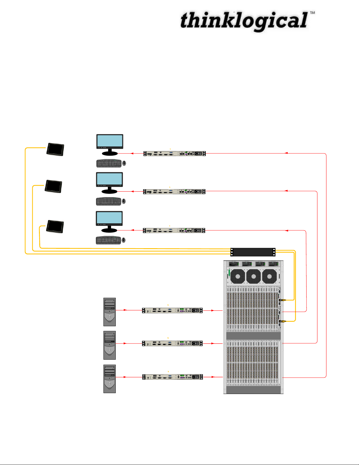
The Logical Solution
The Touch Panel allows user-friendly access to the Thinklogical™ GUI for simple actions to be
made with the touch of the screen. The unit connects independently to a network and with a onetime configuration, the set-up is easily performed. The Touch Panel displays the Thinklogical™
GUI on a 5.7” LCD which allows control of the switching between source computer or video
entities and user display destinations (desktops, theaters, conference rooms, editing suites, control
consoles, video walls, biomedical imaging arenas, satellite mapping, etc). The Touch Panel is
available in a range of sizes, which allows flexibility and convenience among applications.
Figure 1: Typical Touch Panel Application using VelocityKVM System 24 Extenders
Revision B JULY 2010
Page 8

2
System Features
Each Touch Panel includes the following features:
5.7" LCD
Easy set-up and installation
Compact Flash and Micro SD slots
USB 2.0 Ports
PS/2 Keyboard/Mouse
+5V Power Supply
RS232 Serial Interface
Audio out
10/100 Mbps Ethernet
Technical Specifications
Operating Temperature 0-60° C (32-140° F)
Physical Dimensions Length: 5.98” (15.2 cm)
Width: 4.41” (11.2 cm)
Height: 1.3” (3.3 cm)
Power Requirements +5 VDC
Power Consumption 1.3A
Weight <1 lb (374 g)
Revision B JULY 2010
Page 9

3
Part 1: Hardware
OFF
/ON
5V
RS232
10/100
Mbps
CF
SD
Compact Flash Card
Micro SD Slot
PS/2 KB/Mouse
USB 2.0 Port
USB 2.0 Port
10/100 Mbps Ethernet
Audio Out
RS-232
DC IN 5V
Power ON/OFF
Power Active LED (Blue)
IDE Active LED (Yellow)
Touchscreen
Contents
When you receive your Thinklogical™ Touch Panel, you should receive the following items:
Touch Panel Unit
Power Supply
CAT5 Cable Assembly, 20 Feet – CBL000001-020FR
Product Manual CD
Product Quick Start Guide
Installation
Connections and installation hardware for the product use industry-standard devices and methods.
All wiring connections to the customer equipment are designed to minimize proprietary or
customized connectors and cabling. Power connections are made with regionally appropriate
power cords and approved methods. Non-supplied cables that may be needed are commercially
available.
Revision B JULY 2010
Figure 2: Touch Panel Diagram
Page 10

4
Set-Up
1. Carefully remove the Touch Panel from its shipping package. Inspect the Touch
Panel to make certain that no damage occurred during shipment. When the Touch
Panel has been inspected and found to be in good condition, the installation process
can begin.
2. Connect the Touch Panel to a suitable power source using the power supply provided.
3. Connect the Touch Panel to the network using the CAT5 cable provided.
4. Turn the Power Switch ON.
5. Repeat Steps 1 through 4 for each additional Touch Panel.
Order of Installation Events
Please refer to the Quickstart Guide included in the contents of the shipment for detailed
instructions. A copy of the Quickstart is also available in Appendix A.
Revision B JULY 2010
Page 11

5
Part 2: Software
IP Address:
192.168.13.XXX
192.168.13.XXX 192.168.13.XXX
192.168.13.XX
192.168.13.X
Administration
Station
Linux Rack-Mount Web Server
VX160
router
Figure 3: Touch Panel and VX160 Set-Up Diagram
How to configure the server
1. Set up the IP address for the server
a. System -> Network -> ...
2. Decide on station names and ports
3. Edit stations.csv
a. Column headings always end with a colon (:)
b. The system ships with default names assigned to every physical port
c. One row will repeat “Source Category:” across multiple columns, with the category
names displayed below
i. (not all headings need a field below them, but every field requires a header
somewhere in the column above it.
ii. The order of the names decides the order the categories will be displayed in the GUI
Revision B JULY 2010
Page 12

6
d. One row of headers will start with the header “Source Name:”. All rows beneath that
row describe source stations.
i. Each source station requires (insert example):
1. Source Name:
2. Chassis Name:
3. Primary Port: (this is the port that has the back channel)
4. (Optional) One or more Port: entries (in case of multi-headed image sources)
5. One or more Category: entries, for organizing stations (more about this later)
6. One or more Viewable: entries, with a group name in each entry, to define
which groups can view this source
7. One or more Takeable: entries, with a group name in each entry, to define
which groups can take control of the keyboard/mouse for this cpu from another
user
4. Decide on permissions and group names
5. Edit stations.csv, add group headings to stations
6. Decide on IP addresses for Touch Panels
7. Edit groups.csv
How to configure the Touch Panel
Each Touch Panel must be configured in order for it to talk to the server. The Touch Panels are
shipped from the factory configured and ready for set-up. Also, they do not lose their configuration
when disconnected or powered off. The only time the Touch Panel may need to be re-configured
is if it takes on a different use or is moved to a different network.
The following instructions need to be followed in order to reconfigure the Touch Panel.
A USB Keyboard and the IP address(es) chosen for the Touch Panel(s) during the
configuration of the server is(are) necessary to perform the Touch Panel configuration.
Note: A USB Keyboard and the IP address chosen during the server
configuration is necessary to perform the configuration of each Touch Panel.
Direct Configuration Set-Up:
1. Attach the USB keyboard to a USB port on the Touch Panel
2. Press Ctrl - Alt - F1 on the Touch Panel to go into text mode
3. When the login appears, type in the following:
username: root
password: emac_inc
Revision B JULY 2010
Page 13

7
Remote Configuration Set-Up: Each Touch Panel is shipped with DHCP enabled by default
1. Attach one or more Touch Panels to a network with a DHCP server
2. Use “ssh” to access each Touch Panel in turn
3. When the login appears, type in the following:
username: root
password: emac_inc
To set up the network:
4. Type cd /etc/network
5. Using vi, edit “interfaces”
6. In the section for eth1,
a. modify dhcp line to say “static”
b. Insert a line “address 192.168.13.161”
(with whatever IP address you‟ve chosen for this Touch Panel)
c. Add “netmask 255.255.255.0”
d. Save and exit
The completed interface file should look something like this after modification:
# /etc/network/interfaces -- configuration file for ifup(8), ifdown(8)
# The loopback interface
auto lo
iface lo inet loopback
allow-hotplug eth0
iface eth0 inet static
address 192.168.13.171
netmask 255.255.255.0
gateway 192.168.13.1
To set the browser to find the server:
7. Type cd/etc/network
8. Using vi, edit “homepage” (a single line file that, by default reads:
“http://192.168.13.9/touch)
a. Change the IP address to match that of the web server machine
b. Save and exit
The files have now been configured, but the Touch Panel will not use them yet:
9. Type “sync”
10. Type “reboot”
Revision B JULY 2010
Page 14
8
Page
Up
Page
Down
Page
Up
Page
Down
The Touch Panel will blank its screen and reboot with new values.
If you are using the Remote Configuration method on multiple Touch Panels, watch to see which
panel blanks and reboots so you can tell which one you‟ve just configured and label it with the
proper IP address.
Using the Touch Panel
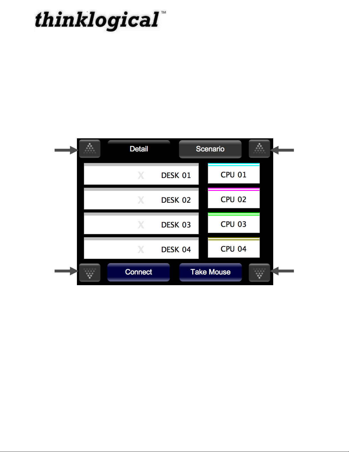
Detail Screen
The Touch Panel will load the operating system, start the GUI, and get the updates from the
server. The following screen should display the GUI:
Figure 4: Touch Panel displaying the GUI
The Touch Panel starts up in “Detail” mode by default.
SOURCES are listed on the right (ex: CPU 01, CPU 02, CPU 03, CPU 04).
DESTINATIONS are listed on the left (ex: DESK 01, DESK 02, DESK 03, DESK 04).
The buttons shown at the bottom of the screen are command buttons which perform a task.
Connect will connect your destination to a source by pressing, where Take Mouse will „take the
mouse‟ from all other connections and give it to the source/destination combination the user has
selected. You can also run Macros by clicking on the Macros button and then run the selected
Macro.
Revision B JULY 2010
Page 15
9
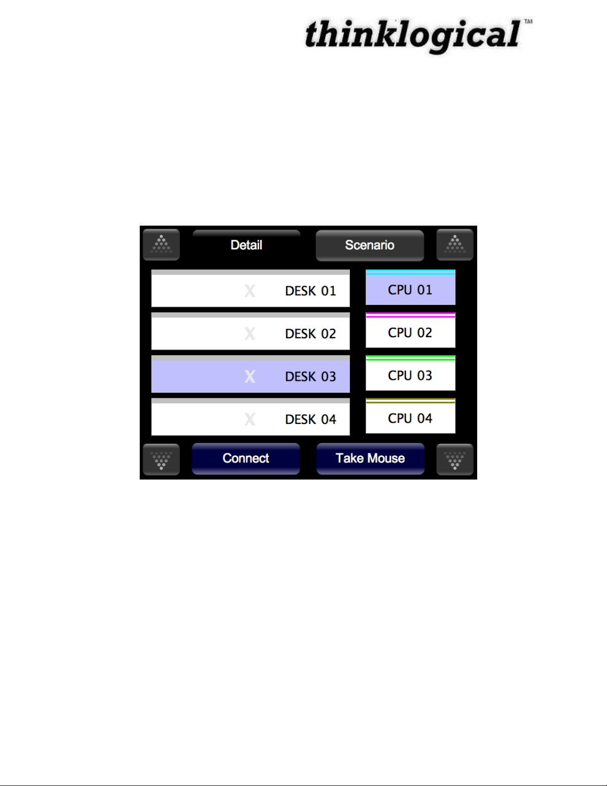
How to Make a Connection
When you click a source, it will highlight in a specific color. You can then click destinations (left
side) to make connections. If a source is still selected, then additional connections to that source
port can still be made by clicking on destination ports. Selections will remain if you need to „Page
Up‟ or „Page Down‟ to show other sources and/or destinations. You may deselect the source port
by simply touching it.
1. Select CPU 01. It will become selected and highlight blue.
2. Select DESK 03. Instead of immediately being connected to CPU 01, it will also become
selected and will highlight blue.
Figure 5: How to Make a Connection, Steps 1 and 2.
3. Press the Connect button at the bottom, left side. The connection is made and is shown
by the „X‟ highlighting blue. By default, the mouse is assigned to this first connection.
The mouse is indicated by the Mouse icon to the right of CPU 01.
Revision B JULY 2010
Page 16

10
Figure 6: How to Make a Connection, Step 3.
4. Press DESK 04, and it will highlight.
Figure 7: How to Make a Connection, Step 4.
Revision B JULY 2010
Page 17

11
5. Press Connect again, and now it is connected as well, indicated by the highlighted X.
Figure 8: How to Make a Connection, Step 5.
How to Break a Connection
From the Detail screen, you can break a connection. Pressing the X between a connected source
and its destination will break that connection.
1. Click on the X between the Source and Destination you wish to disconnect. CPU 01
and DESK 04 are no longer connected as shown in the screen in Figure 8.
Revision B JULY 2010
Page 18

12
Figure 9: How to Break a Connection, Step 1.
Showing the Active backchannel on the Touch Panel
Unlike video connections, data connections are bidirectional, to and from a source computer.
Although there can be many connections from a source computer, there can only be one
connection to a source computer. This connection back to the source computer, called the
backchannel, allows a keyboard, mouse, and other devices to communicate with the source
computer. The GUI interface marks the backchannel by showing a Mouse icon to the right of
the source.
How to Move a Backchannel from a Data Port (Take the Mouse)
From the Detail screen, you can move the backchannel to another destination, also known as
„Take the Mouse‟. Figure 9 shows a source (CPU 01) connected to 2 destinations (DESK 03 and
DESK 04). DESK 03 has the backchannel to CPU 01. The backchannel is represented by the
mouse icon.
1. Click on a destination that already is connected but does not have the mouse (ex: DESK
04). The destination (DESK 04) will highlight.
Revision B JULY 2010
Page 19

13
Figure 10: DESK 03 has the backchannel to CPU 01; it‟s represented by the mouse icon.
DESK 04 is connected to CPU 01 and is selected.
2. Press „Take Mouse‟. The mouse icon will move to the new destination (DESK 04) and is
now a backchannel.
Figure 11: DESK 04 is now the backchannel.
Revision B JULY 2010
Page 20

14
Scenario (Macro) Screen
A second page available on the Touch Panel is “Scenario”, selected by the tab at the top. From
this page, Scenarios (or Macros) can be executed.
Macros can be used to perform multiple functions at the same time. If there is a series of
commands that must be performed again and again, a macro can do this with a single click.
Macros are small scripts that can be run from the web browser. They can connect ports, connect
"stations" (collections of ports, also sometimes known as "groups"), disconnect ports and stations,
and even execute other macros. The user is not allowed to create, edit, or delete macros
from the Touch Panel.
Pressing the Scenario (Macro) button (top, towards the right) takes the panel to „Scenario‟ (Macro)
mode with the following display:
Figure 12: The Scenario (Macro) screen
The example in Figure 11 shows two Scenarios (Macros) displayed, named “Macro 1” and “Macro
2”. Each scenario (macro) is executed immediately when its button is pressed.
Note: The user is not allowed to create, edit, or delete macros from the Touch
Panel.
Revision B JULY 2010
Page 21

15
Part 3: Thinklogical™ Support
Customer Support
Thank you for choosing a Thinklogical™ product for your application. We appreciate your
business and are dedicated to helping you successfully use our product. Thinklogical™ is here to
help you.
Thinklogical™ is an engineering company and you will receive the information you require directly
from our most knowledgeable engineers. We believe that the first line of support is the design
engineer that developed the product. Therefore, your questions will be handled promptly by our
in-house engineers who are most familiar with your products.
To contact Thinklogical™, use the following telephone numbers and internet-based methods.
Website
Check out our website for current product offerings, support information and general information
about all of the products we offer.
Our internet website offers product information on all current systems, including technical
specification sheets and installation guides (for viewing online or for download), product diagrams
showing physical connections and other information you might need.
Internet: www.thinklogical.com
Note: Most online documents are stored as Adobe Acrobat “PDF” files. If you
do not have the Adobe Acrobat reader needed to view PDF files, visit www.adobe.com
for a download.
Email
Thinklogical™ is staffed Monday through Friday from 8:30am to 5:00pm, Eastern Time Zone. We
will try to respond to your email inquiries promptly, use the following email addresses for your
different needs:
info@thinklogical.com – Information on Thinklogical™ and our products.
sales@thinklogical.com – Sales Department - orders, questions or issues.
support@thinklogical.com – Product support, technical issues or questions, product
repairs and request for Return Authorization.
Revision B JULY 2010
Page 22

16
Telephone
Telephone Sales: Contact our expert, technically oriented sales staff via telephone in Milford, CT
at (203) 647-8700 or if in the continental US, you may use our toll-free number (800) 291-3211.
We are here Monday through Friday from 8:30am to 5:00pm, Eastern Time Zone. Ask for their
direct dial phone number when you call.
Telephone Product Support: Contact Product Support via telephone in Milford, Connecticut at
(203) 647-8700. The support lines are manned Monday through Friday, 8:30am to 5:00pm,
Eastern Time Zone.
International Sales: Please contact our US sales staff in Milford, CT at (203) 647-8700. We are
here Monday through Friday, 8:30am to 5:00pm, Eastern Time Zone (same as New York City). If
leaving a voice message, please provide a “best time to call back” so we may reach you at your
convenience.
Our switchboard attendant will direct your call during regular business hours. We have an
automated attendant answering our main telephone switchboard after regular business hours and
holidays. You can leave voice messages for individuals at any time. Our Sales Representatives
have direct numbers to speed up your next call to us.
Fax
Our company facsimile number is (203) 783-9949. Please indicate the nature of the fax on your
cover sheet and provide return contact information.
Product Support
Thinklogical‟s™ support personnel are available Monday through Friday from 8:30am to 5:00pm,
Eastern Time Zone. If your application might require assistance at some time outside of our
normal business hours, please contact us beforehand and we will do our best to make
arrangements to help you with your Thinklogical™ products.
Product Serial Number
Thinklogical™ products have a unique serial number, imprinted on an adhesive label that is fixed
to the bottom of the chassis. The serial number includes a date-code. The format for the date-code
is 2 digits for the month, 2 digits for the day and 2 digits for the year, plus two or three digits for a
unique unit number. This serial number is also found on the original shipping carton.
Warranty
Thinklogical™ warrants this product against defects in materials and workmanship for a period of
one year from the date of delivery. Thinklogical™ and its suppliers disclaim any and all other
warranties.
Note: Thinklogical™ Inc. products carry a one year warranty, with longer term
available at time of purchase on most products. Please refer to your product invoice
for your products Warranty Terms & Conditions.
Revision B JULY 2010
Page 23

17
Defect remedy shall be, repair or replacement of the product, provided that the defective product is
returned to the authorized dealer within a year from the date of delivery.
If you wish to return your device, contact the Thinklogical™ authorized dealer where you
purchased the device, or if you purchased directly, call Thinklogical™ at 1-800-291-3211 (USA).
Return Authorization
In the event you must return a product to Thinklogical™ directly:
Contact Customer Support at 1-800-291-3211 or 203-647-8700.
Customer Support will ask you to describe the problem and will issue you a Return
Merchandise Authorization number (RMA#).
Pack the device in its original box, if possible, and return it with the RMA# on the box.
Note: Do not return a product to Thinklogical™ without a Return Material
Authorization.
Return address for products with Return Material Authorization:
Attn: RMA#
100 Washington Street
Milford, CT 06460 USA
PH: 800-291-3211 (USA only)
Our Address
If you have any issue with the product, have product questions or need technical assistance with
your Thinklogical™ system, please call us at 800-291-3211 (USA only) or (203) 647-8700 and let
us help. If you‟d like to write us, our mailing address is:
Thinklogical™ Inc.
100 Washington Street
Milford, CT 06460 USA
Revision B JULY 2010
Page 24

18
SOURCE 2
VX160
router
Linux Rack-Mount Web Server
DEV
LINE IN
MIC OUT
HID
P
S
2
LOCAL
FROM CPU
USB HID
HOST
CNTRL
UPDATES
SER IAL PORT
DVI OUT
1
DVI OUT
2
DVI IN
2
DVI IN
1
L
1
L
2
L
3
USB 1.1
Velocitykvm-24
U
P
D
A
T
E
S
LINE OUT
MIC IN
PS
2
USB HID
HOST
CNTRL
SER IAL PORT
DVI OUT
1
DVI OUT
2
DVI OUT
2
DDC
DVI OUT
1
DDC
USB
1
.
1
L
2
L
1
L
3
WORK STATION 3
U
P
D
A
T
E
S
LINE OUT
MIC IN
PS
2
USB HID
HOST
CNTRL
SER IAL PORT
DVI OUT
1
DVI OUT
2
DVI OUT
2
DDC
DVI OUT
1
DDC
USB
1
.
1
L
2
L
1
L
3
WORK STATION 2
U
P
D
A
T
E
S
LINE OUT
MIC IN
PS
2
USB HID
HOST
CNTRL
SER IAL PORT
DVI OUT
1
DVI OUT
2
DVI OUT
2
DDC
DVI OUT
1
DDC
USB
1
.
1
L
2
L
1
L
3
WORK STATION 1
DEV
LINE IN
MIC OUT
HID
P
S
2
LOCAL
FROM CPU
USB HID
HOST
CNTRL
UPDATES
SER IAL PORT
DVI OUT
1
DVI OUT
2
DVI IN
2
DVI IN
1
L
1
L
2
L
3
USB 1.1
DEV
LINE IN
MIC OUT
HID
P
S
2
LOCAL
FROM CPU
USB HID
HOST
CNTRL
UPDATES
SER IAL PORT
DVI OUT
1
DVI OUT
2
DVI IN
2
DVI IN
1
L
1
L
2
L
3
USB 1.1
TOUCH PANEL 2
TOUCH PANEL 3
TOUCH PANEL 1
SOURCE 1
SOURCE 3
QUICK START GUIDE
Velocitykvm-24
Velocitykvm-24
Velocitykvm-24
Velocitykvm-24
Velocitykvm-24
RECEIVER
RECEIVER
RECEIVER
TRANSMITTER
TRANSMITTER
TRANSMITTER
Touch Panel Application with the Velocitykvm-24 Fiber Optic Extension System
1
8
2
3
4
5
7
6
9
STEP 1: Connect
the fibers of each
Work Station to the
Downstream ports
of the Router.
STEP 2: Connect the
AC Power Cords to
the Router‟s power
supplies and plug
each of them into a
standard AC source.
STEP 3: Ensure the Receivers‟ Power Switches at each Work Station are in the
OFF position. Connect the AC Power Cords to the Receivers and plug each of
them into a standard AC source. Turn the Power Switches ON.
STEP 4: Connect the Touch Panels to a Network Hub with CAT5 cables.
STEP 5: Connect the Router and Web Server to the Network Hub with CAT5 cables.
STEP 6: Connect the destination Video and KMASS devices to each Work Station‟s
Receiver. Ensure each device is turned ON.
STEP 7: Connect the fibers
from each Transmitter to the
Router‟s Upstream ports.
STEP 8: Ensure that each
Transmitter Power Switch is in
the OFF position. Connect the
AC Power Cords to the
Transmitters and plug each of
them into a standard AC
source. Turn each unit ON.
STEP 9: Connect the source
Video and KMASS devices to
each Work Station‟s
Transmitter. Ensure the
source CPU is turned on and
all system functions are
operating properly.
L1, L2, L3
L1, L2, L3
L1, L2, L3
L2, L1, L3
L2, L1, L3
L2, L1, L3
L2 L1 L3
L1 L2 L3
L1 L2 L3
L1 L2 L3
L2 L1 L3
L2 L1 L3
Fiber Optic Cables: L1►Data from Tx to Rx & Video 1. L2◄Data Rx to Tx. L3►Video 2
NETWORK HUB
Appendix A: Quickstart Guide
Revision B JULY 2010
 Loading...