

Page 1
Page 2

®
TLX Matrix Switch ASCII API V5 ii Rev. I, January 2019
Copyright Notice
Copyright © 2019. All rights reserved. Printed in the U.S.A.
Thinklogical, A BELDEN BRAND
100 Washington Street
Milford, Connecticut 06460 U.S.A.
Telephone: 1-203-647-8700
All trademarks and service marks are property of their respective owners.
Subject: Product Manual: TLX Matrix Switch ASCII API V5
Revision: I, January 2019
®
Page 3

®
TLX Matrix Switch ASCII API V5 iii Rev. I, January 2019
Table of Contents
PREFACE................................................................................................................................................ 1
About Thinklogical® ...................................................................................................................... 1
About This Manual ....................................................................................................................... 2
Note and Warning Symbols ...................................................................................................... 2
Font Conventions Used in this Manual ..................................................................................... 2
REGULATORY & SAFETY REQUIREMENTS ........................................................................................ 3
Symbols Found on Our Products .................................................................................................. 3
Regulatory Compliance ................................................................................................................ 3
North America .......................................................................................................................... 3
Australia & New Zealand .......................................................................................................... 4
European Union ....................................................................................................................... 4
Declaration of Conformity ..................................................................................................... 4
Standards with Which Our Products Comply ............................................................................................ 4
Supplementary Information .......................................................................................................... 4
OVERVIEW ............................................................................................................................................. 5
API Version 4 Commands That Were Modified in Version 5 ......................................................... 5
Uni-directional vs. Bi-directional ................................................................................................... 5
CONVENSIONS ................................................................................................................................ ...... 5
Port Numbers ............................................................................................................................... 5
Results ......................................................................................................................................... 6
COMMANDS ........................................................................................................................................... 6
CONNECTION COMMANDS ......................................................................................................... 6
Connect ........................................................................................................................................ 6
Disconnect ................................................................................................................................... 7
Macro ........................................................................................................................................... 7
XPUT ........................................................................................................................................... 8
STATUS COMMANDS ................................................................................................................... 8
STATUS ....................................................................................................................................... 8
XSTATUSIO and XSTATUSOI ..................................................................................................... 9
XGET ........................................................................................................................................... 9
SYSTEM INFORMATION COMMANDS ........................................................................................ 9
XVERSION ................................................................................................................................... 9
XINSTALLED ............................................................................................................................. 10
XMAXCARDS* ........................................................................................................................... 10
Table 1: XMAXCARDS Return Values .................................................................................. 10
XMAXPORTS ............................................................................................................................. 10
XCTIME...................................................................................................................................... 11
XTYPE**..................................................................................................................................... 11
XLASTEVENT ............................................................................................................................ 12
XPORTCONFIG ......................................................................................................................... 12
XRESET ..................................................................................................................................... 12
XALARM .................................................................................................................................... 12
XQUIT ........................................................................................................................................ 12
XCRON and XCROFF ................................................................................................................ 12
XOPTIONS ................................................................................................................................. 13
XHELP ................................................................ ....................................................................... 14
* Modified from Version 4
** New to Version 5
Page 4

®
TLX Matrix Switch ASCII API V5 iv Rev. I, January 2019
DIAGNOSTIC COMMANDS......................................................................................................... 15
XTEST1...................................................................................................................................... 15
XTEST2...................................................................................................................................... 15
XTEST3...................................................................................................................................... 15
TLX MATRIX SWITCH PORT NUMBERING ......................................................................................... 16
The TLX12.....................................................................................................................................16
The TLX24…………………………………………………………………………………………………16
The TLX48 ................................................................................................................................. 16
The TLX80 ................................................................................................................................. 17
The TLX160 ............................................................................................................................... 17
The TLX320 ............................................................................................................................... 17
The TLX640 ............................................................................................................................... 18
The TLX1280 ............................................................................................................................. 19
Error and Status Codes.................................................................................................................20
Product Serial Number ........................................................................................................................... 20
Connection to the Product ...................................................................................................................... 20
THINKLOGICAL® SUPPORT ................................................................................................................ 21
CUSTOMER SUPPORT .................................................................................................................. 21
Website ...................................................................................................................................... 21
Email .......................................................................................................................................... 21
Telephone .................................................................................................................................. 21
Fax ................................................................................................ ............................................. 21
PRODUCT SUPPORT ..................................................................................................................... 22
Warranty..................................................................................................................................... 22
Return Authorization ................................................................................................................... 22
Our Addresses ........................................................................................................................... 22
APPENDIX A: Switch Status Broadcast ............................................................................................. 23
APPENDIX B: Sample Commands ...................................................................................................... 23
APPENDIX C: Connecting Extenders ................................................................................................. 24
APPENDIX D: Point-to-Point Connection Mode ................................................................................. 26
MADE IN USA
Page 5

TLX Matrix Switch ASCII API V5 1 Rev. I, January 2019
Preface
About Thinklogical A BELDEN BRAND
Thinklogical, A BELDEN BRAND, is the leading manufacturer and provider of fiber-optic and CATx
video, KVM, audio, and peripheral extension and switching solutions used in video-rich, big-data
computing environments.
Thinklogical offers the only fiber-optic KVM matrix switches in the world that are
accredited to the Common Criteria EAL4, TEMPEST SDIP 24 Level B, and NATO NIAPC
Evaluation Scheme: GREEN and the U.S. DoD DISA JITC UCR 2013 APL information
assurance standards. And Thinklogical Velocity products are the first system with both
KVM and video matrix switching capabilities to be placed on the Unified Capabilities
Approved Product List (UC APL) under the Video Distribution System (VDS) category.
Thinklogical products are designed and manufactured in the USA and are certified to the
ISO 9001:2015 standard.
Thinklogical is headquartered in Milford, Connecticut and is owned by Belden, Inc., St. Louis, MO
(http://www.belden.com). For more information about Thinklogical products and services, please
visit www.thinklogical.com.
Page 6

®
TLX Matrix Switch ASCII API V5 2 Rev. I, January 2019
About This Manual
This document describes the command set used to control Thinklogical's TLX series of Matrix
Switches. The TLX Matrix Switch API commands are based on the command set used by our VX
Matrix Switches and are detailed in the document: Matrix_Switch_ASCII_API.
• 5.00-A Initial release (created from the VX Matrix Switch version of this manual: V4.5-1 Rev E)
Note and Warning Symbols
Throughout this manual, you will notice certain symbols that bring your attention to important
information. These are Notes and Warnings. Examples are shown below.
Note: Important Notes appear in blue text preceded by a yellow exclamation point
symbol, as shown here.
A note is meant to call the reader’s attention to helpful or important information at a point in the text
that is relevant to the subject being discussed.
Warning! All Warnings appear in red text, followed by blue text, and preceded by a red
stop sign, as shown here.
A warning is meant to call the reader’s attention to critical information at a point in the text that is
relevant to the subject being discussed.
Font Conventions Used in this Manual
The following fonts and colors are used throughout this document to help differentiate between file
names, commands, outputs and document names (lower- & upper-case letter o and zero, shown
right):
Filenames Font: Courier New - 35-35-22 oO0
Linux Command Entered by the User Font: Consolas - 196-89-17 oO0
Output from a Command Font: Consolas – 0-128-128 oO0
Document_Name* Font: Georgia – 83-129-53 oO0
* These and other documents may be found on our ftp site:
ftp://ftp.thinklogical.com/TLxSwitch/Documentation/
or on our web site:
http://www.thinklogical.com/user_manuals
BEFORE STARTING ANY PROCEDURE, IT IS RECOMMENDED
THAT YOU READ THE INSTRUCTIONS THOROUGHLY!
Page 7
®
TLX Matrix Switch ASCII API V5 3 Rev. I, January 2019
Regulatory & Safety Compliance
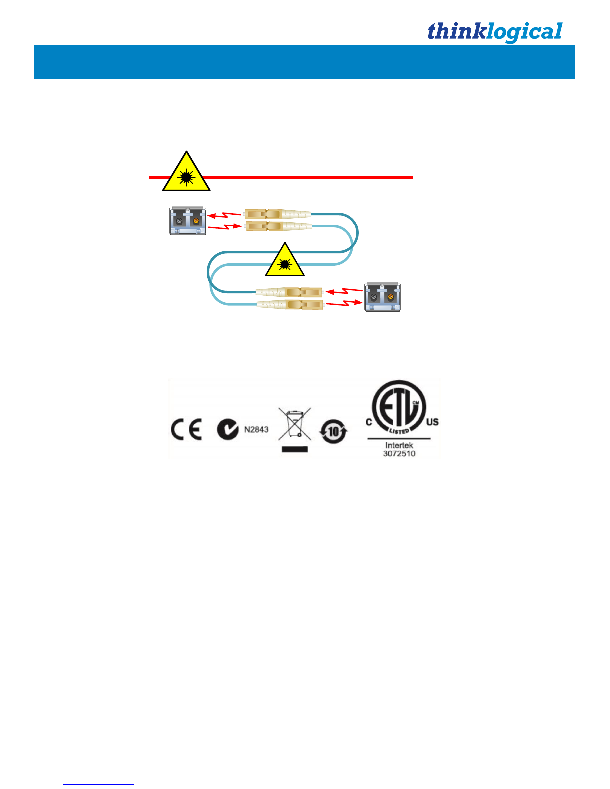
Class 1 Laser Information
TL
X Matrix Switches, like all Thinklogical® fiber-optic products, are designed and identified as
Class 1 LASER
products.
This means the maximum permissible exposure (MPE) cannot be exceeded when viewing the
laser with the naked eye or with the aid of typical magnifying optics (e.g. telescope or microscope).
Symbols Found on Our Products
Markings and labels on our products follow industry-standard conventions. Regulatory markings found on our
products comply with all required domestic and many international requirements.
Regulatory Compliance
Thinklogical’s® products are designed and made in the U.S.A. These products have been tested by a certified
testing laboratory and found compliant with the following standards for both domestic USA and many
international locations:
North America
Safety
UL 62368-1:2014Ed.2
CSA C22.2#62368-1:2014Ed.2
LASER Safety
CDRH 21 CFR 1040.10
Class 1 LASER Product
Canadian Radiation Emitting Devices Act, REDR C1370
IEC 60825:2001 Parts 1 and 2
Class 1 LASER Product
Electromagnetic Interference
FCC 47CFR Part 15 Subpart B: 2013 Class A
Industry Canada ICES-003: 2016 Ed. 6
SFP
Modules
Fiber-Optic
Cables
Class 1 Lasers
CLASS 1 LASERS do not require any special
precautions under conditions of normal use.
Page 8

®
TLX Matrix Switch ASCII API V5 4 Rev. I, January 2019
Australia & New Zealand
This is a Class A product. In a domestic environment this product may cause radio interference, in which case
the user may be required to take corrective action.
European Union
Declaration of Conformity
Manufacturer’s Name & Address: Thinklogical, A BELDEN BRAND
100 Washington Street
Milford, Connecticut 06460 USA
Thinklogical’s products comply with the requirements of the Low Voltage Directive 2006/95/EC, the EMC
Directive 2004/108/EC, the RoHS Directive 2011/65/EU, the WEEE Directive 2012/19/EU and carry the
markings accordingly.
Standards with Which Our Products Comply
Safety
IEC 62368-1:2014Ed.2+C1
CB Scheme Certificate
Electromagnetic Emissions
CENELEC EN 55022:2010 +AC:2011
Electromagnetic Immunity
EN 55024:2011+A1
CENELEC EN 55032:2015
EN61000-3-2:2000 Harmonics
EN61000-3-3:2008 Flicker
EN 61000-4-2:2009 Electro-Static Discharge Test
EN 61000-4-3:2006 A1:2008, A2:2010 Radiated Immunity Field Test
EN 61000-4-4:2004 Electrical Fast Transient Test
EN 61000-4-5:2006 Power Supply Surge Test
EN 61000-4-6:2009 Conducted Immunity Test
EN61000-4-11:2004 Voltage Dips & Interrupts Test
Supplementary Information
The following statements may be appropriate for certain geographical regions and might not apply to your
location:
• This Class A digital apparatus meets all requirements of the Canadian Interference-Causing Equipment
Regulations. Cet appareil numérique de la classe A respecte toutes les exigencies du
Règlement sur le matérial brouilleur du Canada.
• This is a Class A product. In a domestic environment, this product may cause radio interference, in which
case the user may be required to take corrective action.
• This equipment has been tested and found compliant with the limits for a Class A digital device, pursuant to
part 15 of the FCC Rules. These limits are designed to provide reasonable protection against harmful
interference when the equipment is operated in a commercial environment. This equipment generates, uses
and can radiate radio frequency energy and, if not installed and used in accordance with the instruction
manual, may cause harmful interference to radio communications in which case the user may be required
to make adequate corrective measures at their own expense.
• This Class A digital apparatus complies with Canadian ICES-003 and has been verified as compliant within
the Class A limits of the FCC Radio Frequency Device Rules (FCC Title 47, Part 15, Subpart B CLASS A),
measured to CISPR 22: 1993 limits and methods of measurement of Radio Disturbance Characteristics of
Information Technology Equipment.
The user may notice degraded audio performance in the presence of electro-magnetic fields
.
Page 9

®
TLX Matrix Switch ASCII API V5 5 Rev. I, January 2019
Overview
This document describes the command set used to control Thinklogical's TLX series of Matrix
Switches. The commands are all ASCII based and are terminated with either a linefeed character or
a carriage-return/linefeed pair. Port numbers are all 4 digits in length and filled with leading zeros
(Example: port 12 is encoded as 0012).
The TLX Matrix Switch API commands are based on the command set used by our VX Matrix Switch
product line and detailed in the document: Matrix_Switch_ASCII_API.
API Version 4 Commands That Were Modified in Version 5
The following commands were modified in Version 5 of the API.
• XDCSTYPE Renamed XTYPE
• XMAXCARDS Returns the maximum number of I/O cards, not half the maximum.
Uni-directional vs. Bi-directional
As used in this document, uni-directional is a connection that is made in only one direction,
from an input to an output. Note that an input may be directed to multiple outputs at one time. The
direction refers to data flow between a transmitter and a receiver or between a receiver and a
transmitter (a backchannel).
Some of our VX Matrix Switches have the capability to create two connections at one time, creating a
bi-directional connection. Bi-directional connections are still possible with TLX Series Matrix Switches
(and in most cases necessary for the correct operation of the switch) but must be created by issuing
two uni-directional commands. The TLX Series Matrix Switches are considered unidirectional devices.
Note: API commands shown in this manual are depicted in UPPER-CASE. This is for
clarity purposes only. The latest API allows commands to be in upper or lower case. Bit 2
(0x04) of the XOPTIONS status result is set to a 1 if the Switch requires upper-case
commands. This bit is there for the instances where a control system must interface with
different models and vintages of our Switches.
This manual reflects version V5.07.02 of the ASCII API.
Conventions
Port Numbers
▪ All port numbers are four places long, begin with 1 and have leading zeros. For example, port 15 is
encoded as 0015.
▪ A port number of 4 zeros is used in response to a status command to signify that no port is in use.
A “zero” port number is not valid in a command string.
▪ A port number of four 9s (9999) in used to signify ALL ports. It is not valid in a response.
For example, to encode all output ports, use: O9999
▪ In the following sections, xxxx is used as a generic input port place holder; yyyy is used as the
output port place holder.
Note: Do not use xxxx or yyyy in a command! Replace each with the appropriate input or
output port number.
Page 10

®
TLX Matrix Switch ASCII API V5 6 Rev. I, January 2019
Results
Results from commands are ASCII strings terminated with a newline (linefeed). The first character is
an 'R', followed by a 4 digit, zero-filled length. The length includes the trailing newline. Following the
length will be either 'OK', or 'ERnnnn'. OK signifies the command was successful, while ERnnnn is an
error code. After the OK or ERnnnn, a comment may appear giving more detailed information.
In the case of a status command, the OK is followed by the status response.
Note: Users must wait for a result response before sending another command.
There are several command line options to available control the output from the API. These options
are described in detail in the document:
Manual_Configuring_the_TLX_ASCII_Interface.
Two of the commonly used options are:
1. [--CR] Include a carriage return on each line output. (Useful for Windows)
2. [--verbose] Append a comment to each response with more information about an error code or
repeat the successful command. Comments will start with the '#' character.
Examples of Verbose Output
Command: CI0004O0007
Normal: R0003OK
Verbose: R0015OK#CI0004O0007
Command: CI0004O0087
Normal: R0007ER0007
Verbose: R0072ER0007#Output port number 87 is out of range (1 thru 80):
'CI0004O0087'
Commands
Connection Commands
Connect
Connect one input port to one or more output ports. Connections are additive.
For example, connecting input 5 to output 7 will result in 7 being added to any existing con-nections
to input 5. The 'i' and 'o' may be of either case.
Format: CixxxxOyyyyO...
• xxxx of all 9's is illegal.
• yyyy of all 9's will connect xxxx to all outputs.
• Connections will be made in the order specified.
Example Results: R0003OK or R0007ERnnnn
____________________________________________________________________________________
Warning! When switching keyboard/mouse channels it is now possible to connect one
keyboard/mouse to multiple computers. Unless the appropriate video connections are
also made, you will be sending commands to computers that you are not currently
viewing. This could have disastrous results!
___________________________________________________________________________________
Page 11

®
TLX Matrix Switch ASCII API V5 7 Rev. I, January 2019
Disconnect
Disconnect one or more input or output ports. Disconnecting an output will only affect that port,
but disconnecting an input will affect every output connected to that input. The 'i' and 'o' may be of
either case.
Format: Dixxxx… or Doyyyy…
• This will disconnect all outputs connected to input port xxxx or will disconnect output port
yyyy only.
• DI9999 or DO9999 will disconnect all the Upstream/Upper ports.
• It is not an error to disconnect a port that is not connected.
Example Results: R0003OK or R0007ERnnnn
Note: To disconnect ALL the ports, you may also use the XPUT (pg. 6) command without
listing any ports.
Macro
Sends a sequence of connect and disconnect commands as one command line. The syntax of
this command is different from the other commands. Unlike the connect and disconnect commands,
there is no I or O character to distinguish input part numbers from output part numbers. This
command combines connects and disconnects in one string. The command may end with a semicolon.
Format: MiiiiOOOOiiiiOOOO...[;]
• iiii - Input port number
• oooo - Output port number
• An input number of 0000 (all zeros) will disconnect the listed output port (same as the DO
command)
• An output number of 0000 (all zeros) will disconnect the listed input port from all connected
outputs (same as the DI command)
• An output number of 9999 will broadcast the input port to all outputs
• Unlike the XPUT command, the switch is not reset before the command is executed
To turn off all the ports, set the input to all zeros and the output to 9999.
An 'M' without inputs or outputs is valid. This allows external systems to determine if the API version
supports the macro command.
Example: M0000001101230000
disconnect output 11
disconnect input 123
Example: M00009999
disconnect all ports
Example Results: R0003OK or R0007ERnnnn
Page 12

®
TLX Matrix Switch ASCII API V5 8 Rev. I, January 2019
XPUT
Restore the entire switch connection state. The output from XGET (pg. 7) is used by this
command.
Format: XPUTstr
• The XPUT command will turn off all outputs and then make the connections that are listed
in 'str', which is the response that was returned from a XGET command.
• XPUT without any ports is valid and is interpreted as a command to disconnect all ports.
Example: XPUTI00010003I00020004I0010001000110012
Example Results: R0003OK or R0007ERnnnn
Status Commands
Status
Return the connection status of an input or output port.
Format: Sixxxx
• Return the list of output ports that are connected to input port xxxx.
• If nothing is connected to port xxxx, 0000 will be returned.
Format: Soyyyy
• Return the input port number that is connected to output port yyyy.
• If nothing is connected to port xxxx, 0000 will be returned.
Example Results (SI):
• RnnnnOKIxxxxOyyyyOyyyyOyyyy... or R0007ERnnnn
• xxxx is connected to output(s) yyyy.
• 0000 means not connected.
Example Results (SO):
RnnnnOKIxxxxOyyyy or R0007ERnnnn
• xxxx is connected to output yyyy.
• 0000 means not connected.
Page 13

®
TLX Matrix Switch ASCII API V5 9 Rev. I, January 2019
XSTATUSIO and XSTATUSOI
These commands return the current switch connection state. The switch state is returned as
pairs of ports: input port and output port for the 'IO' command and output port and input port for the
'OI' command. A data pair is returned for each active connection. The semi-colon is always present in
an 'OK' response.
These commands use four-digit, zero-filled decimal values. For example: the value 12 is encoded as:
0012. There is only one 'I' or 'O' in the response. It is immediately after the 'OK' and is there to identify
which port (input or output) appears first in the data pair. The order in which the ports are listed is not
defined.
Format: XSTATUSIO
Format: XSTATUSOI
This will return a (very) long string listing every connection. The connection list consists of pairs of
port numbers.
Example Results:
• XSTATUSIO: R0027OKI0010012300120015;
• XSTATUSOI: R0027OKO0015001201230010;
• XSTATUSOI: R0011OKO;
• XSTATUSOI: R0019OKO0015001201230010;
• R0005OKI;
• R0005OKO;
• R0007ERnnnn
XGET
Like the XSTATUSIO and XSTATUSOI commands, this command returns the entire switch
connection state. The output from this command is used by the XPUT command (see pg. 6).
Format: XGET
• This will return a (very) long string listing every connection. The connection list consists of
a series of input port numbers, followed by output port numbers.
• The XPUT command requires all the characters from the response that come after the 'OK'.
Example Results:
• R0039OKI00010003I00020004I00100010I00110012
• R0030OKI00010003I00100010I00110012
• R0012OKI01230145
• R0003OK or R0007ERnnnn
System Information Commands
XVERSION
Returns the API program version number.
Format: XVERSION
Example Results: R0009OKV5.00
Page 14

®
TLX Matrix Switch ASCII API V5 10 Rev. I, January 2019
XINSTALLED
Returns an inventory of installed I/O cards. A zero means the card is not installed and a one
means the card is installed. The number of cards determines the number of zeros and ones returned
and the number of cards varies for each TLX model. The cards are listed from left to right, with the
leftmost digit used for the card that has port 1.
Format: XINSTALLED
Example Results: R0006OK111 TLX48
R0023OK00000000000100000000 TLX320
XMAXCARDS (Modified from Version 4)
Returns the maximum number of I/O cards in the switch.
This is a change from V4 of the API. V4 returned half the number of I/O cards, except for the MX48
which returned 3 (the actual number of cards).
Bit 3 of XOPTIONS may be used to determine if XMAXCARDS returns half the number of cards or
the actual number of cards (the default). See XOPTIONS, pg. 10.
Model
Upstream
Cards
Downstream
Cards
Total Cards
Returned Value
XOPTIONS bit 3
TLX12 1 0 1 1
1
TLX24 1 0 1 1
1
MX48 3 0 3 3
1
TLX48 3 0 3 3
1
TLX80
16 0 16
16
1
TLX160
16 0 16
16
1
VX320-Video
20 0 20
10
0
TLX320
20 0 20
20
1
VX640
32 0 32
16
0
TLX640
32 0 32
32
1
Table 1: XMAXCARDS Return Values
The TLX48 example below shows the message returned when the 'verbose' API command line option
is enabled. Here, the API command is returned at the end of the response message.
Format: XMAXCARDS
Example Results: R0017OK0003#XMAXCARDS TLX48
R0007OK0020 TLX320
R0007OK0032 TLX640
XMAXPORTS
Returns the maximum number of non-blocking ports in the switch. This may also be interpreted
as the maximum port number allowed in a command.
Format: XMAXPORTS
Example Results: R0007OK0048 TLX48
R0007OK0320 TLX320
R0007OK0640 TLX640
Page 15

®
TLX Matrix Switch ASCII API V5 11 Rev. I, January 2019
XCTIME
The latest API now collects data on how long a port is connected. This is a cumulative amount,
not how long the current connection has been in place. It is kept for both the input and output sides of
a connection. For example, if the only input port ever used was port 1, then it would have a non-zero
total, while all other input port totals would be zero. If input port 1 was only connected to output ports
3, 5 and 7, then those three ports would have non-zero totals and all other output port totals would be
zero.
Format: XCTIMEnnnn
Example Results: xget
R0012OKI00010001
xctime0001
R0032OK0001,612817,612817#xctime0001
xctime0001
R0032OK0001,612837,612837#xctime0001
xctime0001
R0032OK0001,612841,612841#xctime0001
xctime0001
R0032OK0001,612849,612849#xctime0001
xput
R0008OK#xput
xctime0001
R0032OK0001,614003,614003#xctime0001
xctime0001
R0032OK0001,614003,614003#xctime0001
ci0001O0002
R0015OK#cI0001O0002
xctime0001
R0032OK0001,614007,614003#xctime0001
xctime0001
R0032OK0001,614011,614003#xctime0001
Input 1 is connected to output 1 in this example (see XGET output). Each time the XCTIME
command is sent, the connection times are increasing. Then the ports are disconnected (XPUT). As
can be seen, the connection times stay the same. Finally input 1 is connected to port 2. As shown,
input 1 times are increasing, but output port 1 times do not change.
XTYPE (New to Version 5)
Returns a string containing the TLX model. This was formerly the command XDCSTYPE but has
been renamed. The old name will still work.
Format: XTYPE
Example Results: R0014OKTLX48Switch
R0015OKTLX320Switch
R0015OKTLX640Switch
Page 16

®
TLX Matrix Switch ASCII API V5 12 Rev. I, January 2019
XLASTEVENT
Returns a time-stamp string that was set the last time a connection was made or broken. This
can be used to determine if the switch status has changed since the last XLASTEVENT command
was issued.
Format: XLASTEVENT
Example Results:
• R0027OKThu Jul 1 11:23:52 2010
XPORTCONFIG
Returns a comma delimited list of three numbers: NU, NB, OFF.
The first number (NU) is the maximum number of uni-directional paths in the system. The second
(NB) is the maximum number of bi-directional paths and the third is currently defined as zero. Note:
TLX switches are uni-directional.
Format: XPORTCONFIG
Example Results:
• R0017OK0048,0000,0000 TLX48
• R0017OK0320,0000,0000 TLX320
• R0017OK0640,0000,0000 TLX640
XRESET
Resets the internal switch hardware to its power on state.
Format: XRESET
Example Results: R0003OK or R0007ERnnnn
XALARM
Returns the Matrix Switch hardware alarm status.
The return value is a decimal number that represents a bit-map of the actual alarm bits. For example,
if 19 is returned, the binary format will be: 10011. This shows that 3 alarms are active (3 bits are '1').
The leftmost bit in the example is bit 4, followed by bits 3, 2, 1 and 0 (the rightmost bit). Bit 0
corresponds to alarm 1, bit 1 to alarm 2, etc.
The alarm bits are defined in the TLX Matrix Switch manual and vary depending on the model.
Format: XALARM
Example Results: R0007OK0522 TLX320
Decimal 522 is 1000001010 in binary (bits 9, 3 and 1 are 'on')
XQUIT
Ends the network connection.
XCRON and XCROFF
Enables or disables sending CR's on each line. XCRON is typically used when a (Windows) telnet
client connecting to the switch requires each line to end with a CR/LF pair.
Format: XCRON or XCROFF
Example Results: R0003OK
Page 17

®
TLX Matrix Switch ASCII API V5 13 Rev. I, January 2019
XOPTIONS
This command returns a numeric response that is a bit map of options available in the version
of the API. The value returned is a four-digit decimal number of the binary bit map. For example, if
the value returned was 0015, then bits 0, 1, 2, and 3 would be on (bit 0 is the lsb).
The following bits are defined:
0: Reserved for HDX Matrix Switches.
1: XTEST2 command is allowed. This is set for the TLX320 and TLX640.
2: Only UPPER-CASE commands are allowed.
3: XMAXCARDS returns the total number of cards allowed in the Matrix Switch (not half the number
as it formerly did).
4: Switch supports point-to-point connection mode.
5: If set, the Switch may send status updates using a Multicast IP address instead of a broadcast IP
address.
6: If set, the Switch supports collection on port connection durations. (see the XCTIME command on
pg. 8)
Format: XOPTIONS
Example Results: R0007OK0007
Sample response:
R0062OK0120#xoptions:Actual_Card_Count P2P Multicast Connect_Time
Page 18

®
TLX Matrix Switch ASCII API V5 14 Rev. I, January 2019
XHELP
Print a list of valid commands. This is a multi-line response that does NOT start with OK or ER or end with a
length. It is intended as a debugging aid and not for use in a production environment. It does not follow
the format rules for command responses. Format: XHELP
Sample response:
Version: V5.07.07 (build: 8)
Usage: tlx320api [options]
---- network options ----
-L|--listen[=]port listen on this port, all addresses (default: 17567)
-N|--connections[=]n set the maximum number of open connections allowed (default: 128)
--mcast[=IP address] replace broadcasts with multicast to this IP address (default:
239.255.13.9)
--noexternalapi only listen on 'localhost' for API connections
--noexternalbcast send the port status only on 'localhost'
---- serial options ----
-S|--serial=device use this serial device (default: /dev/ttymxc1)
--serial=none disables the API serial port /dev/ttymxc1
-B|--baud[=]speed sets serial baud rate (default: 9600)
---- generic options ----
--CR output CRLF instead of just LF (network connection only)
--facility[=]name syslog facility reporting level (default is local4)
valid names: auth, daemon, user, local0 through local7
see the man page for rsyslog.conf for more information
-D|--debug write debug messages to the log file (multiple options increase the
debug level)
--api write API messages received to the log file (level: NOTICE)
--avr write control commands to the log file (level: NOTICE)
--clog write connection status changes to the log file (level: NOTICE)
--log_ip include the IP address with each API message that is logged (level:
NOTICE)
--delay[=]delay in ms, how long an output must remain off, default is 300 ms.
minimum is 50ms, maximum is 1000ms, 0 will disable the delay
-b|--bcast[=]period in ms, how long between port status broadcasts, default is 4000 ms.
minimum is 500, maximum is 15000, 0 will disable the broadcast
if multicast is enabled, it will use this time setting
--bcast=0 will disable: broadcasts, multicasts, and the 'restore
connections' feature to disable network broadcasts but keep the
'restore' feature, use the --noexternalbcast option
--idle[=]seconds network connections idle for at least these many seconds are
candidates to be forcibly closed when a new connection is made and there
are no available sockets. Setting it to 0 will disable this feature. The
default setting is 60 seconds.
-V|--verbose enable error text in responses
-h|--help display this help and exit
-v|--version output version information and exit
Default (no options) is to listen on socket 17567 at all IP addresses
send to socket 27567 at 127.0.0.1
accept commands from the RS232 port
broadcast switch status every 4000 milliseconds on port 17564
signal SIGUSR1 will toggle api debug logging (--api)
signal SIGUSR2 will toggle control debug logging (--avr)
signal SIGHUP will force the API to reread the P2P csv files located in /var/local/router/p2p/
Page 19

®
TLX Matrix Switch ASCII API V5 15 Rev. I, January 2019
Diagnostic Commands
These commands are used to test the ability of the switch to make connections. They will
connect each of the input ports to each of the output ports in one of three ways, as described below.
XTEST1
Connects all the ports on the Matrix Switch (n to n).
Connects input 1 to output 1, input 2 to output 2, …input n to output n...
Format: XTEST1
Example Result: R0003OK
XTEST2
Connects all the ports on the TLX320 and TLX640 Matrix Switches.
This test is only available on the TLX320 and TLX640, due to their underlaying hardware design and
will activate a set of hardware paths that do not exist on the other TLX models.
On the TLX320, it connects:
input 1 to output 161, input 2 to output 162, …input 160 to output 320…
input 161 to output 1, input 162 to output 2, …input 320 to output 160...
On the TLX640, it connects:
input 1 to output 640, input 2 to output 639, …input 640 to output 1...
Format: XTEST2
Example Result: R0003OK
XTEST3
Connects all the ports on the Matrix Switch for testing CATx Extenders.
Connects input 1 to output 2, input 2 to output 1, …input n-1 to output n, output n to input n-1...
Format: XTEST1
Example Result: R0003OK
Note: If you want to verify that all the outputs on the switch are working, the command
Cixxxxo9999 will connect input xxxx to ALL the output ports. The XTEST commands
require an input signal on ALL inputs, whereas the Cixxxxo9999 only requires a signal on
input xxxx.
Page 20

®
TLX Matrix Switch ASCII API V5 16 Rev. I, January 2019
TLX Matrix Switch Port Numbering
When making or breaking connections on a TLX Matrix Switch, it is important to identify the
'direction' of the connection. In this context, connection direction refers to data flow from the
extender transmitter to the extender receiver, or receiver to transmitter.
• Transmitter to Receiver data flow is called an 'upstream to downstream' connection.
• Receiver to Transmitter data flow is a 'downstream to upstream' connection (sometimes
referred to as the 'backchannel').
The port numbering schemes for each of the TLX Matrix Switch models are shown below.
TLX12, TLX24, TLX48, TLX80, TLX160, TLX320, TLX640 and TLX1280 connections can be made
between any ports on any card.
The TLX12
The TLX24
The TLX48
TLX48 I/O Cards are verticle cards mounted horizontally.
Port numbers begin at the bottom card and start from the right side.
Page 21

®
TLX Matrix Switch ASCII API V5 17 Rev. I, January 2019
The TLX80
TLX80 Port numbers begin at the bottom and start with the left I/O Card.
The TLX160
TLX160 Port numbers begin at the bottom and start with the left I/O Card.
The TLX320
Controller Cards
Page 22

®
TLX Matrix Switch ASCII API V5 18 Rev. I, January 2019
The TLX640
TLX640 Port numbers begin at the Lower Card Cage and start with the left I/O Card (Ports 1-
20), proceeding up to the Upper Card Cage’s left I/O Card (Ports 21-40).
Port numbers then move to the second I/O Card on the Lower Card Cage (Ports 41-60) and proceed
up to the second I/O Card on the Upper Card Cage (61-80), etc.
Primary Controller
Card
Secondary
Controller Card
Page 23

®
TLX Matrix Switch ASCII API V5 19 Rev. I, January 2019
The TLX1280
Port numbering begins at the bottom of the TLX1280’s chassis and starts with Card 1, the leftmost I/O card of
the Lower Card Cage. Card 2 is directly above Card 1 in the Upper Card Cage. When installing fewer than 40
I/O Cards, cards slots may be chosen at the user’s discretion. Each card slot has a port number designation
printed above the card for easy reference.
Page 24

®
TLX Matrix Switch ASCII API V5 20 Rev. I, January 2019
Error and Status Codes
1.1 0001 – Syntax error.
1.2 0002 – The command is missing an input port field.
1.3 0003 – The command is missing an output port field.
1.4 0004 – The command has multiple input fields, but only 1 is allowed.
1.5 0005 – The command has multiple output fields, but only 1 is allowed.
1.6 0006 – The input port value is out of range.
1.7 0007 – The output port value is out of range.
1.8 0008 – The command contains an invalid character.
1.9 0009 – A port value of 9999 is not allowed in this command.
1.10 0010 – A SNMP error occurred (only a DCS switch will generate this error).
1.11 0011 – An error occurred while attempting an internal fork command.
1.12 0012 – API received a command that is not allowed.
1.13 0013 – Not enough memory to process the command
1.14 0014 – File I/O error; an error occurred while reading or writing a file.
1.15 0015 – The switch control process is not responding.
1.16 0016 – The command references multiple chassis, but the Switch only has one.
1.17 0017 – A macro was sent with a semi-colon ( ; ) but the switch is unidirectional.
Unidirectional switches do not allow port numbers after a semi-colon.
1.18 0018 – Partition or Restrictive port failure.
1.18.1 0019 – The connection cannot be made because of a blocking condition in the
internal switch matrix.
Error 10: This error code is no longer in use.
Error 11, 13, 14, 15: Internal program error: Contact Thinklogical® if you get this message.
Error 12: API V5 does not use this error code.
Product Serial Number (MM-YY1234)
Thinklogical products have a unique serial number, which includes a date-code, printed on an
adhesive label that is affixed to the unit. The format for the date-code is 2 digits for the month, dash, 2
digits for the year, plus at least four digits for a unique unit number. For example:
05-170129 indicates the unit was built in the 5th month of 2017 and is unit number 129.
Connection to the Product
Connections and installation hardware for our products use industry-standard devices and
methods. All wiring connections to the customer equipment are designed to minimize proprietary or
customized connectors and cabling. Power connections are made with regionally appropriate power
cords and approved methods.
Page 25

®
TLX Matrix Switch ASCII API V5 21 Rev. I, January 2019
Thinklogical Support
Customer Support
Thinklogical® is an engineering company and we offer the best customer support available. You can
count on our most knowledgeable engineers to assist you with any questions or problems. We
won’t be satisfied until you are satisfied.
Thank you for choosing Thinklogical® products for your application.
We appreciate your business and are dedicated to helping you successfully use our products.
is always here to help you.
To contact us, please use the following telephone numbers and internet-based methods:
®
Website
Check out our website at www.thinklogical.com for current products, support documents and useful information
about all the products and services we offer, including technical specification sheets, quick-start guides and
product manuals (for viewing online or for download).
Most online documents are stored as Adobe Acrobat “PDF” files. If you do not have the Adobe Acrobat reader
needed to view PDF files, visit www.adobe.com for a download.
Email
Thinklogical is staffed Monday through Friday from 8:30am to 5:00pm, Eastern Time Zone. We will do our
best to respond to your email inquiries promptly. Please use the following email addresses:
info@thinklogical.com – Information on Thinklogical and our products.
sales@thinklogical.com – Sales Department - orders, questions or issues.
support@thinklogical.com – Product support, technical issues or questions, product repairs and request for
Return Merchandise Authorization.
Telephone
Thinklogical Operator 1-203-647-8700
Product & Customer Support: 1-203-647-8798
Please contact our expert sales staff in Milford, CT. We are here Monday through Friday from 8:30am to
5:00pm, Eastern Time Zone. We’ll provide a representative’s direct dial phone number when you call.
If leaving a voice message, please provide a preferred time to call back so we may reach you at your
convenience.
Our switchboard attendant will direct your call during regular business hours. We have an automated attendant
answering our main telephone switchboard after regular business hours and on holidays. Please leave a voice
message at any time.
Fax
Our company facsimile number is 1-203-783-9949. Please indicate the nature of the fax on your cover sheet
and provide return contact information.
Page 26

®
TLX Matrix Switch ASCII API V5 22 Rev. I, January 2019
Product Support
Thinklogical’s support personnel are available Monday through Friday, from 8:30am to 5:00pm, Eastern
Time Zone. If your application requires assistance at some time outside of our normal business hours,
please contact us beforehand, if possible, and we will have someone available to assist you.
Warranty
Thinklogical warrants this product against defects in materials and workmanship for a period of one year from
the date of delivery, with longer term available at time of purchase on most products. Thinklogical and its
suppliers disclaim all other warranties. Please refer to your product invoice for the Warranty Terms &
Conditions.
Defect remedy shall be the repair or replacement of the product, provided that the defective product is returned
to the authorized dealer within a year from the date of delivery.
If you wish to return your device, contact the Thinklogical authorized dealer where you purchased the device,
or if you purchased directly, call Thinklogical at 1-800-291-3211 (USA).
Return Authorization
If you must return a product to Thinklogical directly, please contact us at 1-800-291-3211 or 1-203-647-8700.
Customer Support will ask you to describe the problem and will issue you a Return Merchandise Authorization
number (RMA#). Pack the device in its original box, if possible, and return it with the RMA# printed on the
outside of the box.
Note: DO NOT return a product to Thinklogical without a Return Merchandise Authorization.
Our Addresses
If you have any product issues or questions or need technical assistance with your Thinklogical system, please
call us at 1-800-291-3211 (USA only) or 1-203-647-8700 and let us help. If you need to write us or return a
product, please use the following address:
Please include the Return Merchandise Authorization number: Thinklogical, A BELDEN BRAND
100 Washington Street
Milford, CT 06460 USA
Attn: RMA#
Website: www.thinklogical.com
Facebook: www.facebook.com/ThinklogicalUSA
LinkedIn: www.linkedin.com/company/thinklogical
Google+: http://plus.google.com/u/0/109273605590791763795/about
YouTube: www.youtube.com/user/thinklogicalNA
Twitter: @thinklogical
Page 27

®
TLX Matrix Switch ASCII API V5 23 Rev. I, January 2019
Appendix A: Switch Status Broadcast
The API program will periodically broadcast the current switch connection map over the network. This
data may be used to keep external systems in sync with the switch. Previously, either the XGET or
XSAVE command was needed to obtain the connection map. In systems with many external controls
trying to stay synchronized to the Matrix Switch, the switch would spend a lot of its resources trying to
answer these status requests.
It is now possible to replace the use of 'broadcast' with the use of 'multicast'. The advantage of
using multicast over broadcast is that multicast packets will be routed past the local subnet,
whereas broadcast packets are not routed.
You may configure the frequency of these messages or disable them altogether.
More information about this feature can be found in the manuals Matrix_Switch_Interfaces and
Manual_Configuring_the_TLX_ASCII_Interface.
Appendix B: Sample Commands
CI0005o0010 Connect Input 5 to Output 10
Si0004 Get the connection status of Input 4
xputI00010003I00020004 Turn off all outputs. Connect Input 1 to Output 3 and connect Input
2 to Output 4
Page 28

®
TLX Matrix Switch ASCII API V5 24 Rev. I, January 2019
Appendix C: Connecting Extenders
The following are sample commands needed to connect selected transmitters and receivers through
a TLX Matrix Switch. These examples will reference the appropriate Quick Start Guide.
A) VEL-24 through a TLX320
Quick Start Guide: VX320Video_VEL-24_VEL-38_QSG
Number of fibers: 3: L1, L2, L3
Backchannel fiber: L2 (data from receiver to transmitter)
Tx24 fiber connections Rx24 fiber connections
• L1 -> 14R L1 -> 15T
• L3 -> 16R L3 -> 16T
• L2 -> 14T L2 -> 15R
Commands: (all upper case)
CI0014O0015 Connects L1 video to RX L1
CI0016O0016 Connects L3 video to RX L3
CI0015O0014 Connects L2 data to RX L2 (backchannel)
Assume a second receiver is now connected as follows:
• L1 -> 25T
• L3 -> 26T
• L2 -> 25R
The commands to connect this receiver to the transmitter are:
CI0014O0025 Connects L1 video to RX L1
CI0016O0026 Connects L3 video to RX L3
Note: Receiver 2 (L2 backchannel data) is NOT connected.
• Receiver 1 has full keyboard/mouse/USB/speaker access.
• Receiver 2 has sound (speakers) but no keyboard/mouse/USB.
To move the keyboard/mouse/USB from Rx 1 to Rx 2, issue the following commands:
DI0015 Disconnects RX 1 L2 (backchannel)
DI0025 Disconnects RX 2 L2 (backchannel)
CI0025O0014 Connects RX 2 L2 data to TX 1 (backchannel)
or
M001500000015000000150014 Macro command that combines all three commands
The two 'DI' commands are sent to insure the keyboard/mouse data only goes to a single
transmitter. If you are certain that there are no other L2 connections in place, you may eliminate
them.
Warning! Eliminating the 'DI' commands will open the possibility of sending keystrokes
and/or mouse commands to multiple servers at the same time – a situation that will lead
to disaster! Always ensure that no other L2 backchannel connections are in place before
eliminating the 'DI' commands!
Page 29

®
TLX Matrix Switch ASCII API V5 25 Rev. I, January 2019
B) VEL-38 through a TLX320
Quick Start Guide: VX320Video_VEL-24_VEL-38_QSG
Number of fibers: 5, L1, L2, L2, L3, L4, L5
Backchannel fiber: L2 (data flows from receiver to transmitter)
Tx38 fiber connections Rx38 fiber connections
• L1 -> 8R L1 -> 9T
• L3 -> 10R L3 -> 10T
• L4 -> 11R L4 -> 11T
• L5 -> 12R L5 -> 12T
• L2 -> 8T L2 -> 9R
Commands: (all upper case)
CI0008O0009 Connects L1 video to RX38 L1
CI0010O0010 Connects L3 video to RX38 L3
CI0011O0011 Connects L4 video to RX38 L4
CI0012O0012 Connects L5 video to RX38 L5
CI0009O0008 Connects L2 data to TX38 L2 (backchannel)
Now connect the TX24 to the RX38:
DI0009 Disconnects RX38 L2 (backchannel)
DO0010 Disconnects RX38 L3 (unused)
DO0012 Disconnects RX38 L5 (unused)
CI0014O0009 Connects TX24 L1 video to RX38 L1
CI0016O0011 Connects TX24 L3 video to RX38 L4
or
M0009000000100000001200000014000900160011 Macro command that combines all three
commands
Page 30

®
TLX Matrix Switch ASCII API V5 26 Rev. I, January 2019
Appendix D: Point-to-Point Connection Mode
Version 5.0 of The API may be configured so that input ports are restricted to one output port
at a time. If input X is first connected to output A, then connected to output B, X will be disconnected
from A and moved to B. This mode is referred to as Point-to-Point mode, or P2P for short.
The P2P definition file is stored on the Controller Card in the following file:
/var/local/router/p2p/upstream.csv
P2P mode is disabled when the definition file does not exist. By default, when there is no file,
input ports may connect simultaneously to any number of output ports. All TLX Matrix Switches are
shipped without a P2P file.
This file is in the form of a comma separated value (csv) file. Each entry in the file is the input port
that you want to restrict to P2P mode. You may have one or more entries per line in the file. The only
characters allowed in the file are the digits 0 through 9, commas, and spaces. Blank lines are allowed.
An example that set ports 1, 2, 3, 4, 9, 11, 15 to P2P mode is:
1,2,3,4
9
11, 15
As a shortcut, you may use the value 9999 to indicate ALL input ports.
If you make changes to this file, you may force the API to reread them by issuing the command:
killall -HUP tlxapi
If P2P files are found at startup, the API will log this to the file: /var/log/api.
An example is shown below.
imx tlxapi[17151]: parsing P2P csv file /var/local/router/p2p/upstream.csv
imx tlxapi[17151]: parse_api_csv_file.c@133: line 1 of csv file /var/local/router/p2p/upstream.csv '1,2,3,4#012'
imx tlxapi[17151]: parse_api_csv_file.c@133: line 2 of csv file /var/local/router/p2p/upstream.csv '9#012'
imx tlxapi[17151]: parse_api_csv_file.c@133: line 3 of csv file /var/local/router/p2p/upstream.csv '11, 15#012'
imx tlxapi[17151]: point-to-point mode enabled
 Loading...