

Page 1
CONTENTS:
StudioPRO Dual-link Extender Transmitter [1]
StudioPRO Dual-link Extender Receiver [1]
USB A-B cable, 6' (CBL-000015-006FR) [1]
Dual-link DVI-D (M to M) cable, 2M (CBL-000023-002MR) [1]
Universal Power Supply (PWR-000022-R) [2]
StudioPRO Extender Product Manual
StudioPRO Extender
Dual-Link DVI, USB 2.0 Video Extension System
QUICK START GUIDE
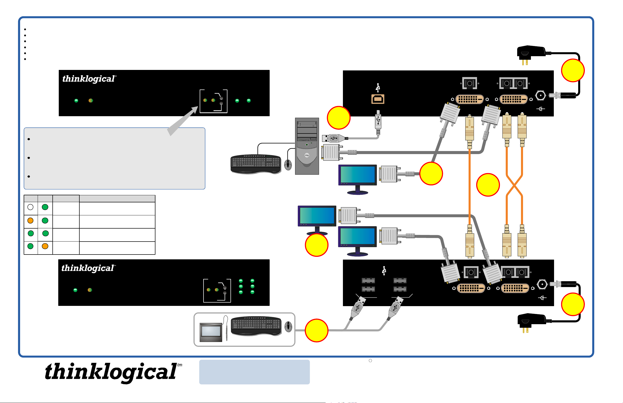
STEP 5:
Connect the supplied +5V power
supply (PWR-000022-R) to the transmitter
and plug it into a standard AC source.
The Future of Access and Control
POWER STATUS
StudioPRO DUAL-LINK EXTENDER TRANSMITTER
Acquire Button
Used to initiate DDC collection. Works with all modes except Pass-Thru. Must
be pressed after switching between DDC modes.
Select Button
Used to select the DDC mode. The modes will cycle through Remote
Dynamic, Remote Static, Pass-Thru and Local Static.
Both Buttons held 5 seconds
Holding both buttons for 5 seconds will reload the default DDC table into the
Tx and switch to Remote Static mode.
LCL REM DDC MODE DESCRIPTION
EDID read from remote display and updated
each time remote display changes.
EDID read from remote display when
acquire button is pressed.
Acts as a direct connection between CPU
and display. No emulation is performed.
EDID read from local display when
acquire button is pressed.
OFF
ORANGE
GREEN
GREEN
GREEN
GREEN
GREEN
ORANGE
REMOTE
DYNAMIC
REMOTE
STATIC
PASS-
THRU
LOCAL
STATIC
StudioPRO Extender
Dual-Link DVI, USB 2.0
Fiber optic transmitter
Powered by
MRTS Technology
STEP 7:
USB and DVI cables
DDC MODE
ACQUIRE
LCL REM
SELECT
STEP 2:
HOSTLINK
Connect the output
display device(s) to the receiver’s
DVI TO DISPLAY ports. The DDC
port is the PRIMARY port and
should be used when there is only
one display device connected.
from the CPU to the
transmitter. Ensure all
system functions are
operating properly.
Connect your
7
CPU
DVI TO Display
2
DVI FROM CPU
DVI Local
Display
DVI TO Display
(DDC)
USB 2.0
6
STEP 6:
monitor to the transmitter’s DVI
LOCAL DISPLAY port.
Connect your local
DVI LOCAL
DISPLAY
4
L1 L3L2
DVI FROM CPU
5
POWER
5VDC
_
+
STEP 4:
your multi-mode fiberoptic cables between
the transmitter and
receiver units (up to
1000 meters).
Connect
The Future of Access and Control
POWER STATUS
StudioPRO DUAL-LINK EXTENDER RECEIVER
STEP 1:
peripheral devices to the
receiver’s USB 2.0 ports.
StudioPRO Extender
Dual-Link DVI, USB 2.0
Fiber optic receiver
Powered by
MRTS Technology
Install any USB
DDC MODE
ACQUIRE
LCL REM
SELECT
LINK
3
4
HOST
1
2
USB Devices
PHONE: (800) 291-3211
WEBSITE: www.thinklogical.com
EMAIL: support@thinklogical.com
L3
1
2
USB 2.0
3
4
DVI TO DISPLAY
(DDC)
STEP 3:
Connect the supplied
L1L2
DVI TO
DISPLAY
+5V power supply (PWR-000022-R)
to the receiver and plug it into a
1
Copyright c 2009. All rights reserved. Printed in the U.S.A. All trademarks and service marks are the property of their respective owners.
standard AC source.
Visit us online at www.thinklogical.com for more product information,
current updates and the complete line of Thinklogical™ products.
POWER
5VDC
_
+
3
StudioPRO_Extender_Dual-Link_Quick_Start_Rev_B
 Loading...