

Page 1
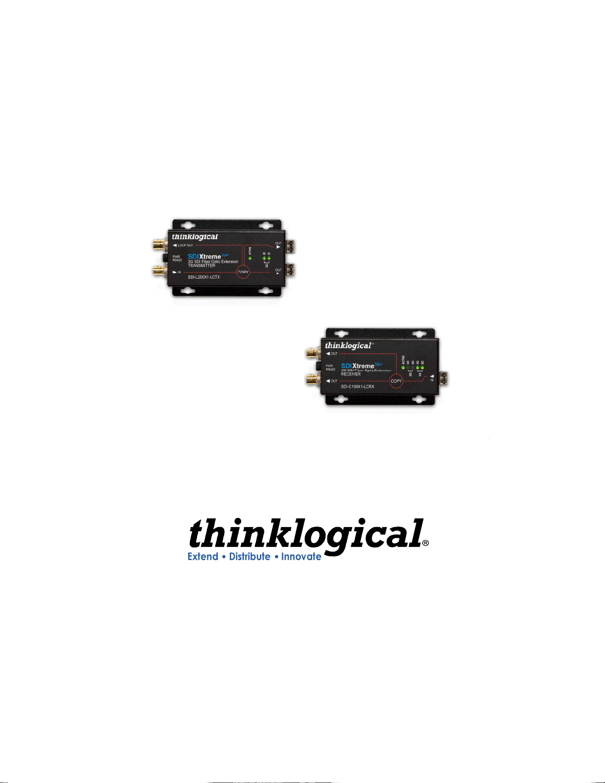
SDIXtreme 3G and 3G+
Product Manual
For all 3G and 3G+ Products
Thinklogical® LLC
100 Washington Street
Milford, Connecticut 06460 U.S.A.
Telephone 203-647-8700
Fax 203-783-9949
Revision E July 2012
Page 2

Copyright Notice
Copyright © 2012. All rights reserved. Printed in the U.S.A.
Thinklogical® LLC
100 Washington Street
Milford, Connecticut 06460 U.S.A.
Telephone 203-647-8700
All trademarks and service marks are property of their respective owners.
Subject:
Revision:
SDIXtreme 3G and 3G+
E,
July 2012
Revision E 2 July 2012
Page 3

Table of Contents
PREFACE .................................................................................................................................. 5
About this Product Manual ...................................................................................................... 5
Conventions Used in this Manual ........................................................................................... 5
INTRODUCTION ....................................................................................................................... 6
The Logical Solution ................................................................................................................ 6
Theory of Operation ................................................................................................................. 6
Technical Specifications ......................................................................................................... 7
PART 1: HARDWARE ............................................................................................................... 9
Contents ................................................................................................................................... 9
Dry Contact Alarm (3G+ Rack-Mount) ...................................................................................10
Hot Swappable Power Supplies (3G+ Rack-Mount) ..............................................................11
Fiber Optic Cable ....................................................................................................................11
Connecting to the Thinklogical® SDI Xtreme 3G ..................................................................12
Installation ...............................................................................................................................12
Set-Up ...........................................................................................................................12
Order of Installation Events ...........................................................................................12
RS422 Pin-outs (3G+) ...................................................................................................12
Part 2: SAFETY REQUIREMENTS ..........................................................................................13
Symbols found on the product ..............................................................................................13
Regulatory Compliance .................................................................................................13
North America ...............................................................................................................13
Australia & New Zealand ...............................................................................................13
European Union ............................................................................................................14
Standards with Which Our Products Comply .................................................................14
Supplementary Information ....................................................................................................15
Product Serial Number ...........................................................................................................16
Connection to the Product .....................................................................................................16
PART 3: THINKLOGICAL® SUPPORT ...................................................................................17
Customer Support ..................................................................................................................17
Website .........................................................................................................................17
Email .............................................................................................................................17
Telephone .....................................................................................................................18
Fax ................................................................................................................................18
Revision E 3
July 2012
Page 4

Product Support ......................................................................................................................18
Warranty ........................................................................................................................18
Our Address ..................................................................................................................19
APPENDIX A: ORDERING INFORMATION .............................................................................20
APPENDIX B: QUICK START GUIDES ...................................................................................26
Revision E 4 July 2012
Page 5
Preface
About this Product Manual
This product manual is divided into three sections: Hardware, Safety Requirements and
Product Support. These are sub-divided to help you easily find the topics and procedures you
are looking for. This manual also contains Appendices.
Part 1 – Hardware: This section of the manual contains all the information and instructions on
how to assemble your equipment.
Part 2 – Safety Requirements: Thinklogical® strongly recommends that you read this section
of the manual prior to starting the hardware assembly.
Part 3 – Product Support: Thinklogical® provides the best customer support available. If you
have any questions or need to contact us, please refer to this section of the manual.
Conventions Used in this Manual
As you read this manual you will notice certain conventions that bring your attention to important
information. These are Notes and Warnings. Examples are shown below.
Note: Important Notes appear in blue text preceded by a yellow exclamation
point symbol, like this.
A note is meant to call the reader’s attention to helpful information at a point in the text that is
relevant to the subject being discussed.
Warning! All Warnings appear in red text, followed by blue text, and
preceded by a red stop sign, like this.
A warning is meant to call the reader’s attention to critical information at a point in the text that is
relevant to the subject being discussed.
Revision E 5
July 2012
Page 6
Introduction
The Logical Solution
The SDI Xtreme 3G and 3G+ product series is available with LC-type fiber connectors.
See Appendix A, for ordering details on the complete line of the Thinklogical SDI Xtreme 3G and
3G+ products.
Theory of Operation
The SDI Xtreme 3G and 3G+ product series is a compact, broadcast quality SDI over fiber
extension system. The system is designed to transmit up to two SD/HD signals or one 3G SDI
signal with or without embedded audio and data, and is SMPTE 424M, 292M, 259M, 372M and
425 level A and B compliant. In addition, this fiber based transport system gives users the
assurance that each signal is immune to video pathological signals over the entire length of the
fiber interconnect, while supporting all pathological patterns at all rates. The system also supports
either single or multimode fiber and is fully compatible with Thinklogical’s VX and HDX Router line
of products.
The SDI Xtreme 3G+ product line has an RS-422 port for device control. These are available in
single or dual chassis models. The dual chassis model houses two separate SDI Xtreme 3G+
units, providing multiple combinations of transmitter and receiver possibilities. There are also
options for loop out and multiplexed signals.
The SDI Xtreme 3G+ Rack Mount (RM) may be used as a transmitter, a receiver, or the slots may
be mixed for flexible configurations (as a transceiver). All SDI interface modules are hotswappable and each has its own RS-422 port. The front panel user interface provides all the
essential features such as status monitoring and link activity for mission critical environments.
System architecture provides hot-swappable, current sharing power supply modules, a critical
component in high up-time environments which typically are supported by more than one power
grid as a failover option. In the unlikely event that a power module fails, there is no interruption to
the component because they are both working all the time. In addition, a dry contact annunciator
provides an alarm warning in the event of a power failure or a unit overheating and a replacement
may be installed with minimal downtime.
Warning! In order to avoid possible exposure to laser energy, it is good
practice to attach the fiber optic cables prior to applying power to the unit. If the
fiber optic cable should become disconnected, DO NOT attempt to look into the
cable or the panel mounted connector.
Revision E July 2012
Page 7

Technical Specifications
Indicators: (3) Power, Data Rate SD, HD, 3G – Lock Detect - Active
Dimensions: 3G = 4.96 x 2.25 x 1.03 (in) – 125.98 x 57.12 x 26.14 (mm)
3G+ = Height: 1.68” (4.3cm) Depth: 3.427” (8.7cm) Width: 5.609”
(14.25 cm)
3G+ RM = Rack Size: EIA 19" Height: 1U-1.72” (4.40 cm) Depth:
18.02" (45.8 cm) Width: 17.49" (44.5 cm)
(Tolerance: ± .039"; .100cm)
Weight: 3G = ~ 1 lb. (~0.45 kg.)
3G+ = <1lb (0.45kg) each Shipping Weight: 4lb (1.81kg) pair
3G+ RM = 15 lbs (4.99 kg) per unit Shipping Weight: 30 lbs (12.25
kg) pair
Supply Voltage 3G and 3G+= 5-14 VDC
3G+ RM =90-264 VAC, 47-63 Hz, Universal AC Power Supplies
Power Consumption: 3G and 3G+ = 6 Watts per unit
3G+ RM = 30 Watts fully loaded per unit
Operating Temperature: 0º C to +50º C; (32°-122°F)
TRANSMITTER Specifications:
Number of SDI Inputs 1 - 2
Data Rate Range 270Mbps to 2.97 Gbps
Supported Standards SMPTE 424M, 292M, 259M, 372M and 425 level A and B compliant
Re-clocked Data Rates 270 Mbps (SMPTE 259M), 1.485 Gbps (SMPTE 292), 2.97 Gbps
(SMPTE 424M)
Equalization Automatic up to 140m of Belden 1694A at 3.0 Gbps, 230m at 1.485
Gbps and 350m at 270 Mbps
Return Loss >10dB up to 2.97 Gbps
Number of Loop Outs 1
Number of Optical Outputs 2
DC Signal Level 800mV ± 10%
DC Offset 0V ± 0.5V
Overshoot < 10% of amplitude
Timing Jitter < 0.2 UI at 270 Mbps; < 1.0 UI at 1.485 Gbps;
< 2 UI at 2.97 Gbps with color bar signal
Alignment Jitter < 0.2 UI at 270 Mbps 1.485 Gbps;
< 0.3 UI at 2.97 Gbps with color bar signal
Rise/Fall Time 0.4 ns to 1.5 ns at 270 Mbps per SMPTE 259M
< 270 ps at 1.485 Gbps per SMPTE 292;
< 135 ps at 2.97 Gbps per SMPTE 424M;
Re-clocking At 270 Mbps, 1.485 Gbps, and 2.97 Gbps
Revision E 7
July 2012
Page 8

OPTICAL Output:
Connector LC receptacle
Fiber Type Multi-mode 10 km Single Mode 40 km Single Mode
Wavelength (nominal) 850nm 1310nm 1550 nm
Emitter Type VCSEL DFB Laser DFB Laser
Output Power (nominal) -4dBm -1.5dBm 2.5dBm
Re-clocking At 270 Mbps, 1.485 Gbps & 2.97 Gbps
RECEIVER Specifications:
Fiber Input
Connector LC receptacle
Fiber Type Multi-mode 10 km Single Mode 40 km Single Mode
Wavelength 770 – 860nm 1260 - 1360nm 1260-1600nm
Minimum Input Sensitivity -12dBm -15dBm -18dBm
Maximum Input Power 0 dBm 0.5dBm -3dBm
Number of SDI Outputs 1 - 2
Signal Level 800mV ± 10%
DC Offset 0V ± 0.5V
Overshoot < 10% of amplitude
Timing Jitter < 0.2 UI at 270 Mbps; < 1.0 UI at 1.485 Gbps;
< 2 UI at 2.97 Gbps with color bar signal
Alignment Jitter < 0.2 UI at 270 Mbps; < 1.0 UI at 1.485 Gbps;
< 0.3 UI at 2.97 Gbps with color bar signal
Rise/Fall Time 0.4 ns to 1.5 ns at 270 Mbps per SMPTE 259M
< 270 ps at 1.485 Gbps per SMPTE 292;
< 135 ps at 2.97 Gbps per SMPTE 424M;
Re-clocking At 270 Mbps, 1.485 Gbps, and 2.97 Gbps
Revision E 8 July 2012
Page 9
Part 1: Hardware
Contents
When you receive your Thinklogical® SDI Xtreme 3G, you should receive the following items:
• SDI Xtreme 3G Hardware
• 5VDC Power Cords – PWR-000022-R (3G, 3G+)
• AC power cord, PWR-000006-R (International connections may differ) – Qty 2 (3G+ Rack-
mount Only)
• Product Manual CD
• Product Quick-Start Guide
All physical connections to the product use industry-standard connectors.
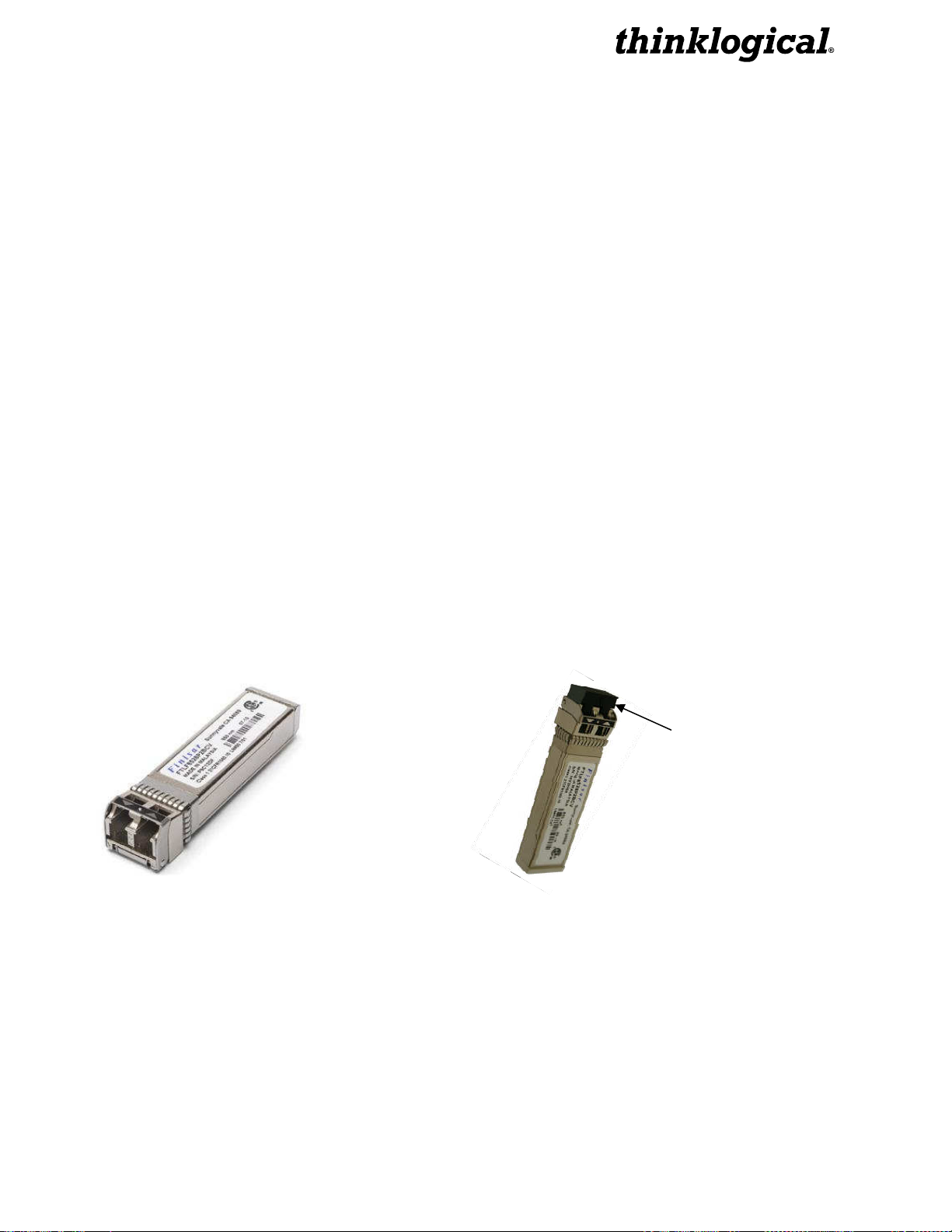
SFP+ Modules
Small Form-factor Pluggable modules are short-wavelength transceivers designed for use in bi-
directional fiber-optic channel links. Each SFP module is hot-pluggable and operates on 3.3VDC.
Each Tx and Rx contains SFP+ modules that serve as the fiber-optic couplers for the fiber cables
to and from the Thinklogical® Tx and Rx units.
Always use dust caps to protect against damage when a fiber optic connector is not
attached to its coupling device (fiber optic equipment, bulkheads, etc.)
Figure 1: SFP+ Module Figure 2: It is good practice to install
dust plugs in unused SFP+s.
Dust Plug
Revision E 9
July 2012
Page 10

ALARM
FANS
PS TEMP
ALARM
FANS
PS TEMP
Dry Contact Alarm (3G+ RM Only)
There are dry contact alarms located on each module in the 3G+ Rack Mount units. When there is
an alarm condition, such as an over temperature condition or an issue with a power supply or fan,
the relay is energized.
Figure 3: Dry Contact Alarm
The dry contact alarm is a Form C contact with the following ratings:
• Nominal switching capacity- 1A, 30VDC, 0.3A 125VAX (resistive load)
• Max. switching power- 30W (DC), 37.5VA (AC) (resistive load)
If there are no current alarm conditions the front panel should read as below with “0” indicating that
there are no failures:
0000 00 0
Figure 4: No Alarm Conditions Present
If an alarm condition is identified, a “1” will indicate a failure as described below:
0100 01 0
Figure 5: Alarm Conditions Present
This example indicates that Fan #2 and Power Supply #1 have each encountered a failure.
Revision E 10 July 2012
Page 11

Hot Swappable Power Supplies (3G+ Rack-Mount Only)
The 3G+ Rack Mount units are equipped with dual hot-swappable, current sharing power supply
modules. Each module has an ON/OFF rocker-type power switch. When the power supply is ON
the LED on the front of the power supply will be lit.
Note: If no modules are plugged in but both power supplies are powered “On”
the front LED status may flash or malfunction, giving you an inconclusive reading
of power supply status for the unit. An uninstalled power module will not report an
alarm.
In the unlikely event that a power module fails, the replacement can be swapped with no
interruption in unit functionality. To hot swap a power supply, simply unscrew the failed module
and replace it with a new power supply module (part number VTM-000001, which can be ordered
from Thinklogical™).
Figure 6: Power Supply Status and Rocker Switch Location
Fiber Optic Cable
Fiber optic cable must run between the Transmitter unit and the Receiver unit. The multi-mode
fiber optic cable must be 50 microns, terminated with a LC-type fiber optic connector and no longer
than 3280 running feet (1000 meters). Single-mode fiber can extend to distances beyond 1000m.
Unlike copper cabling, fiber optic cable requires special handling. A small speck of
dust or a scratch to the ferrule tip can attenuate the optical signal, making the fiber cable
unusable.
Warning! The ends of the connectors (the ferrule) should never come in contact
with any foreign object, including fingertips.
Warning! Minimum bend radius must be 3”. Be careful not to pinch the fiber
when using ties.
Revision E 11
July 2012
Page 12

Connecting to the Thinklogical® SDI Xtreme 3G
Installation
All physical connections to the product use industry-standard connectors. Non-supplied cables
that may be needed are commercially available. All connections are found on the rear of the unit.
Set-Up
Note: To avoid inadvertent exposure to the lasers, the fiber optic cables
should be attached to the SDI Xtreme 3G prior to powering up the units.
Order of Installation Events
Refer to the Quick Start Guides in Appendix B on page 23.
RS-422 (3G+ Products Only)
The RS-422 connector on 3G+ models is wired to emulate an SMPTE 207M Machine Control
Pin-out.
• In Rack Mount products jumper J5 may be used to flip the transmit and receive polarities
on both TX and RX boards.
• In Stand Alone products jumper J8 may be used to flip the transmit and receive polarities
on both TX and RX boards.
Note: For devices that use straight pinned cables, the jumpers must be in the
same position on both the TX and RX to function correctly.
The RS-422 pin-out is
:
Revision E 12 July 2012
Page 13

Part 2: Safety Requirements
Symbols found on the product
Markings and labels on the product follow industry-standard conventions. Regulatory markings
found on the products comply with requirements.
Regulatory Compliance
Thinklogical® products are designed and made in the U.S.A. Products have been tested by a
nationally recognized testing laboratory and found to be compliant with the following standards
(both domestic USA and many international locations).
North America
These products comply with the following standards:
Safety
ANSI/UL60950-1: 1st Edition (2003)
CAN/CSA C22.2 No. 60950-1-03
LASER Safety
CDRH 21CFR 1040.10
Class 1 LASER Product
Electromagnetic Interference
FCC CFR47, Part 15, Class A
Industry Canada ICES-003 Issue 2, Revision 1
Australia & New Zealand
This is a Class A product. In a domestic environment this product may cause radio interference, in
which case the user may be required to take adequate measures.
Revision E 13
July 2012
Page 14

European Union
Declaration of Conformity
Manufacturer’s Name & Address: Thinklogical®
100 Washington Street
Milford, Connecticut 06460 USA
Telephone (203) 647-8700
Product Name
Model: SDI Xtreme 3G
These products comply with the requirements of the Low Voltage Directive 72/23/EEC and the
EMC Directive 89/336/EEC.
Standards with Which Our Products Comply
Safety
CENELEC EN 60950-1, (2006)
LASER Safety
IEC60825:2001 Parts 1 and 2
Class 1 LASER Product
Electromagnetic Emissions
EN55022: 1994 (IEC/CSPIR22: 1993)
EN61000-3-2/A14: 2000
EN61000-3-3: 1994
Electromagnetic Immunity
EN55024: 1998 Information Technology Equipment-Immunity Characteristics
EN61000-4-2: 1995 Electro-Static Discharge Test
EN61000-4-3: 1996 Radiated Immunity Field Test
EN61000-4-4: 1995 Electrical Fast Transient Test
EN61000-4-5: 1995 Power Supply Surge Test
EN61000-4-6: 1996 Conducted Immunity Test
EN61000-4-8: 1993 Magnetic Field Test
EN61000-4-11: 1994 Voltage Dips & Interrupts Test
Revision E 14 July 2012
Page 15

Supplementary Information
The following statements may be appropriate for certain geographical regions and might not apply
to your location.
This Class A digital apparatus meets all requirements of the Canadian Interference-Causing
Equipment Regulations.
Cet appareil numérique de la classe A respecte toutes les exigencies du Règlement sur le mat
érial brouilleur du Canada.
Warning! This is a Class A product. In a domestic environment, this product
may cause radio interference, in which case the user may be required to take
adequate measures.
Note: This equipment has been tested and found to comply with the limits for a
Class A digital device, pursuant to part 15 of the FCC Rules. These limits are
designed to provide reasonable protection against harmful interference when the
equipment is operated in a commercial environment. This equipment generates,
uses and can radiate radio frequency energy and, if not installed and used in
accordance with the instruction manual, may cause harmful interference to radio
communications in which case the user may be required to take adequate
corrective measures at their own expense.
Note: This Class A digital apparatus complies with Canadian ICES-003 and has
been verified as being compliant within the Class A limits of the FCC Radio
Frequency Device Rules (FCC Title 47, Part 15, Subpart B CLASS A), measured to
CISPR 22: 1993 limits and methods of measurement of Radio Disturbance
Characteristics of Information Technology Equipment.
Note:
electromagnetic fields
Note:
keyboard cable may be needed to comply with Immunity Requirements
The user may notice degraded audio performance in the presence of
.
If using a keyboard that is noise susceptible, a ferrite ring on the
Revision E 15
July 2012
Page 16

Product Serial Number
Thinklogical® products have a unique serial number, imprinted on an adhesive label that is fixed to
the bottom of the chassis. The serial number includes a date-code. The format for the date-code is
2 digits for the month, 2 digits for the day and 2 digits for the year, plus two or three digits for a
unique unit number. This serial number is also found on the original shipping carton.
Connection to the Product
Connections and installation hardware for our products use industry-standard devices and
methods. All wiring connections to the customer equipment are designed to minimize proprietary
or customized connectors and cabling. Power connections are made with regionally appropriate
power cords and approved methods.
Revision E 16 July 2012
Page 17

Part 3: Thinklogical® Support
Customer Support
Thinklogical® is an engineering company and you will receive the information you require directly
from our most knowledgeable engineers. We believe that the first line of support is the design
engineer that developed the product. Therefore, your questions will be handled promptly by our
in-house engineers who are most familiar with your products.
Website
Check out our website for current product offerings, support information and general information
about all of the products we offer.
Our internet website offers product information on all current systems, including technical
specification sheets and installation guides (for viewing online or for download), product diagrams
showing physical connections and other information you might need.
Internet: www.thinklogical.com
Note: Most online documents are stored as Adobe Acrobat “PDF” files. If you
do not have the Adobe Acrobat reader needed to view PDF files, visit www.adobe.com
for a download.
Email
Thinklogical® is staffed Monday through Friday from 8:30am to 5:00pm, Eastern Time Zone. We
will try to respond to your email inquiries promptly, use the following email addresses for your
different needs:
info@thinklogical.com – Information on Thinklogical® and our products.
sales@thinklogical.com – Sales Department - orders, questions or issues.
support@thinklogical.com – Product support, technical issues or questions, product
repairs and request for Return Authorization.
Revision E 17
July 2012
Page 18

Telephone
Telephone Sales: Contact our expert, technically oriented sales staff via telephone in Milford, CT
at (203) 647-8700 or if in the continental US, you may use our toll-free number (800) 291-3211.
We are here Monday through Friday from 8:30am to 5:00pm, Eastern Time Zone. Ask for their
direct dial phone number when you call.
Telephone Product Support: Contact Product Support via telephone in Milford, CT at
(203) 647-8700. The support lines are manned Monday through Friday, 8:30am to 5:00pm,
Eastern Time Zone.
International Sales: Please contact our US sales staff in Milford, CT at (203) 647-8700. We are
here Monday through Friday, 8:30am to 5:00pm, Eastern Time Zone (same as New York City). If
leaving a voice message, please let us know the best time to call back so we may reach you at
your convenience.
Our switchboard attendant will direct your call during regular business hours. We have an
automated attendant answering our main telephone switchboard after regular business hours and
holidays. You can leave a voice message for an individual at any time. Our sales representatives
have direct numbers for your convenience.
Fax
Our company facsimile number is (203) 783-9949. Please indicate the nature of the fax on your
cover sheet and provide return contact information.
Product Support
Thinklogical’s® support personnel are available Monday through Friday from 8:30am to 5:00pm,
Eastern Time Zone. If your application requires assistance at some time outside of our normal
business hours, please contact us beforehand and we will do our best to make arrangements to
help you with your Thinklogical™ products.
Warranty
Thinklogical, LLC (“Thinklogical”) warrants this product against defects in materials and
workmanship for a period of one (1) year from the date of delivery (ordinary wear and tear
excluded). This limited warranty does not cover defects resulting from (i) use of the product other
than as described in the applicable documentation for the product; (ii) modifications to or repairs of
the product that are made by any party other than Thinklogical or a party acting on Thinklogical’s
behalf, or (iii) combination of the product with third party products that is not consented to by
Thinklogical. Occurrences of events described in (i) – (iii) shall void the foregoing warranty. This
warranty gives you specific legal rights, and you may also have other rights which vary from state
to state.
Except for the express warranty set forth above, to the fullest extent permitted under
applicable law, Thinklogical, LLC and its suppliers disclaim any and all other warranties,
express and implied, including without limitation the implied warranties of merchantability,
fitness for a particular purpose, title and non-infringement.
Revision E 18 July 2012
Page 19

If the defective product is returned to the authorized dealer within one (1) year of the delivery date,
repair or replacement of the product will be made. Repairs may be made with refurbished parts. If
repair or replacement is not possible, Thinklogical may keep the defective product and refund the
amount that you paid for the defective product. These are Thinklogical’s sole obligations, and your
exclusive remedies, for a breach of the limited warranty set forth above.
To return a defective product, contact the Thinklogical authorized dealer from whom you
purchased the product. Do not return a product directly to Thinklogical without prior authorization
from your dealer.
If you have received prior authorization from your dealer and are returning a product directly to
Thinklogical:
1. Contact a sales representative or Customer Support at 800-291-3211 or 203-647-8700.
2. Describe the product defect and Customer Support will issue a Return Merchandise
Authorization Number (RMA#).
3. Pack the product in its original packing, if possible, and write the RMA number on the box.
4. Return the product to:
Thinklogical, LLC
Attn: RMA# [Insert the RMA# issued to you by Thinklogical™ here.]
100 Washington Street
Milford, CT 06460 USA
Our Address
If you have any issue with the product, have product questions or need technical assistance with
your Thinklogical® system, please call us at 800-291-3211 (USA only) or 203-647-8700 and let
us help. If you’d like to write us, our mailing address is:
Thinklogical® Inc.
100 Washington Street
Milford, CT 06460 USA
Revision E 19
July 2012
Page 20

Appendix A: Ordering Information
Thinklogical's SDI Xtreme Optics for 3G, 3G+, 3G+ Rack-mount
Part Number Description
SDI FIBER OPTIC EXTENDER OPTICS OPTIONS for SINGLE MODE
VOP-S19 SDI Xtreme 3G Optics Option, Single Mode 4km, 1 SFP Dual Fiber, LC
VOP-S20 SDI Xtreme 3G Optics Option, Single Mode 10km, 1 SFP Dual Fiber, LC
VOP-S21 SDI Xtreme 3G Optics Option, Single Mode 30km, 1 SFP Dual Fiber, LC
VOP-S29 SDI Xtreme 3G Optics Option, Single Mode 4km, 2 SFP Four Fibers, LC
VOP-S30 SDI Xtreme 3G Optics Option, Single Mode 10km, 2 SFP Four Fibers, LC
VOP-S58 SDI Xtreme 3G Optics Option, Single Mode 30km, 2 SFP Four Fibers, LC
SDI FIBER OPTIC EXTENDER OPTICS OPTIONS for MULTI-MODE
VOP-M18 SDI Xtreme 3G Optics Option, Multi-Mode, 1 SFP Dual Fiber, LC
VOP-M21 SDI Xtreme 3G Optics Option, Multi-Mode, 2 SFP Four Fibers, LC
Thinklogical's SDI Xtreme 3G
Part Number Description
SDI-L10001-LCTX SDI Xtreme 3G Transmitter, One Input with Loop Out, LC
SDI-C10001-LCRX SDI Xtreme 3G Receiver, One SFP, 2 Outputs, LC
Revision E 20 July 2012
Page 21

Revision E 21
July 2012
Page 22

Revision E 22 July 2012
Page 23

Revision E 23
July 2012
Page 24

Revision E 24 July 2012
Page 25

Revision E 25
July 2012
Page 26

Appendix B: Quick Start Guides
Revision E 26 July 2012
Page 27

Revision E 27
July 2012
Page 28

Revision E 28 July 2012
Page 29

Revision E 29
July 2012
 Loading...