

Page 1

PRODUCT MANUAL
3G SDI to HDMI Converter and
3G SDI to HDMI Converter/Extender
Thinklogical, LLC®
100 Washington Street
Milford, Connecticut 06460 U.S.A.
Telephone: 1-203-647-8700
Fax: 1-203-783-9949
www.thinklogical.com
Page 2

®
3 G S D I t o H D M I C o n v e r t e r M a n u a l , R e v . D , A p r i l , 2 0 1 3
P a g e 2
3G SDI to HDMI
Converter
®
Copyright Notice
Copyright © 2013. All rights reserved. Printed in the U.S.A.
Thinklogical, LLC®
100 Washington Street
Milford, Connecticut 06460 U.S.A.
Telephone: 1-203-647-8700
All trademarks and service marks are property of their respective owners.
Subject: 3G SDI to HDMI Converter/ 3G SDI to HDMI Converter-Extender Product Manual
Revision: Rev D, April 2013
Page 3

®
3 G S D I t o H D M I C o n v e r t e r M a n u a l , R e v . D , A p r i l , 2 0 1 3
P a g e 3
Table of Contents
Preface 3
About This Product Manual 3
Conventions Used in this Manual 3
Laser Information 3
1 Introduction 4
1.1 Contents 4
1.2 Product Overview 4
2 System Features 5
2.1 General System Features 5
2.2 Technical Specifications 6
3 Connections 8
3.1 Connecting to the 3G SDI to HDMI Converter/Extender 8
3.2 Connecting to the 3G SDI to HDMI Converter 9
3.3 RS-232 Pin Out 9
3.4 User Menu Configurations 10
4 Regulatory and Safety Compliance 18
4.1 Symbols Found on the Product 18
4.2 Regulatory Compliance 18
North America 18
Australia & New Zealand 18
European Union 18
4.3 Standards with Which Our Products Comply 18
4.4 Supplementary Information 19
4.5 Product Serial Number 20
4.6 Connections to the Product 20
5 Thinklogical® Support 20
5.1 Customer Support 20
5.1.1 Website 20
5.1.2 Email 21
5.1.3 Telephone 21
5.1.4 Fax 21
5.2 Product Support 21
5.2.1 Warranty 21
5.2.2 Return Authorization 22
Appendix A: Application Diagrams 23
Appendix B: Quick Start Guide 26
Appendix C: GUI 27
Page 4
®
3 G S D I t o H D M I C o n v e r t e r M a n u a l , R e v . D , A p r i l , 2 0 1 3
P a g e 4
PREFACE
BEFORE STARTING ANY PROCEDURE, IT IS RECOMMENDED
THAT YOU READ THE INSTRUCTIONS THOROUGHLY!
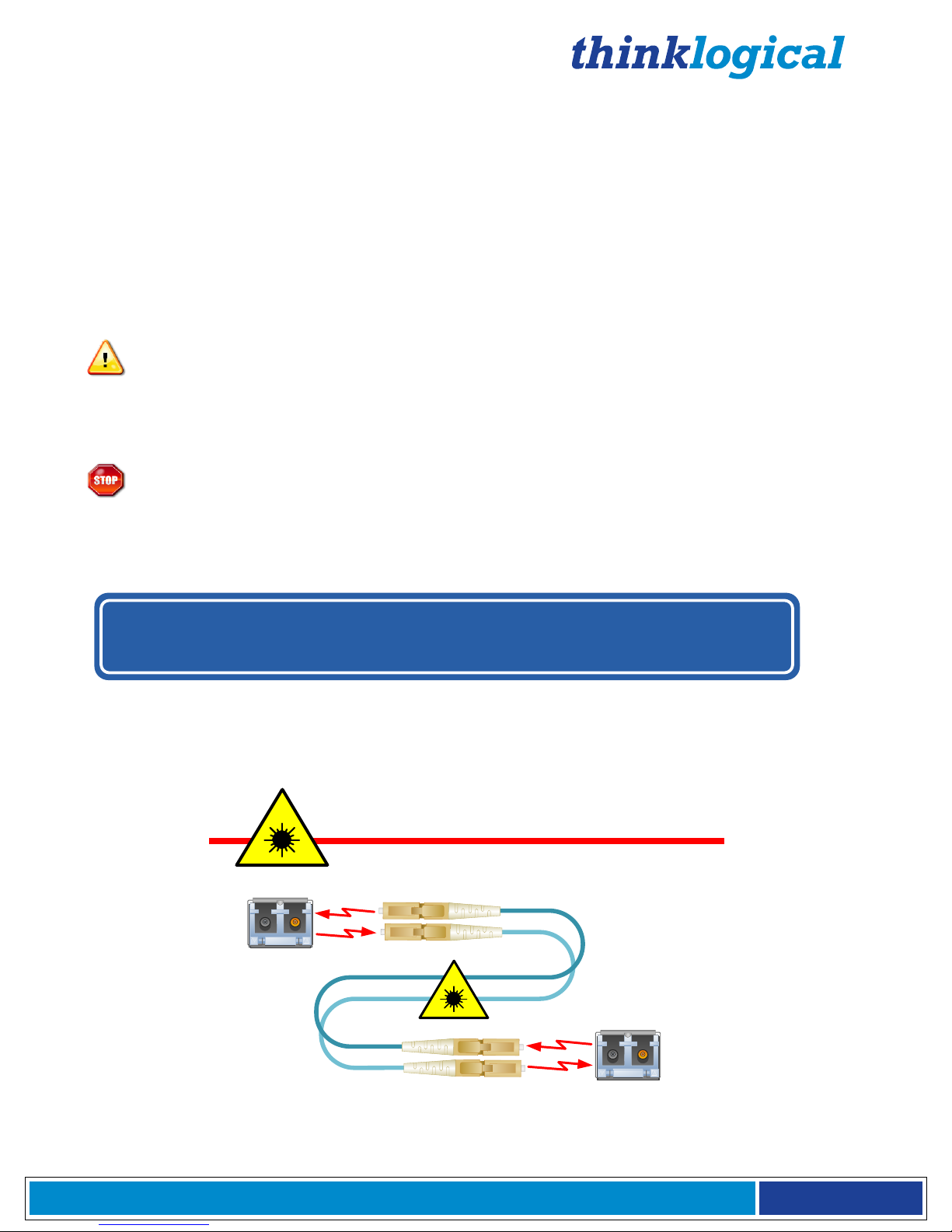
CLASS 1 LASERS do not require any special
precautions under conditions of normal use.
SFP
Modules
Fiber-Optic
Cables
Class 1 Lasers
About this Product Manual
This manual is divided into five sections: 1. Introduction, 2. System Features, 3. Connecting the 3G
SDI to HDMI Converter, 4. Regulatory and Safety Compliance and 5. Thinklogical Support. These
are sub-divided to help you find the topics and procedures you are looking for. This manual also
contains Appendices.
Conventions Used in this Manual
As you read this manual you will notice certain conventions that bring your attention to important
information. These are Notes and Warnings. Examples are shown below.
Note: Important Notes appear in blue text preceded by a yellow exclamation point
symbol, as shown here.
A note is meant to call the reader’s attention to helpful information at a point in the text that is relevant
to the subject being discussed.
Warning! All Warnings appear in red text, followed by blue text, and preceded by a red
stop sign, as shown here.
A warning is meant to call the reader’s attention to critical information at a point in the text that is
relevant to the subject being discussed.
Laser Information
Many Thinklogical® products, including
and identified as
Class 1 LASER products.
3G SDI to HDMI Converter/Extenders,
are designed
Page 5
®
3 G S D I t o H D M I C o n v e r t e r M a n u a l , R e v . D , A p r i l , 2 0 1 3
P a g e 5
1. Introduction
RESOLUTION
RES
SEL
SDI
IN OUT LAN
HDMI
OUT
Power
5VDC
Update
RS-232
3G SDI to HDMI
Converter
®
1.1. Contents
When you receive your Thinklogical® 3G SDI to HDMI Converter, you should find the following items:
3G SDI to HDMI Converter (SDC-000001) or
3G SDI to HDMI Converter/Extender (SDC-000001-LC)
AC/DC adapter universal input 90-264 VAC – PWR-000022-R
3G SDI to HDMI Converter product manual.
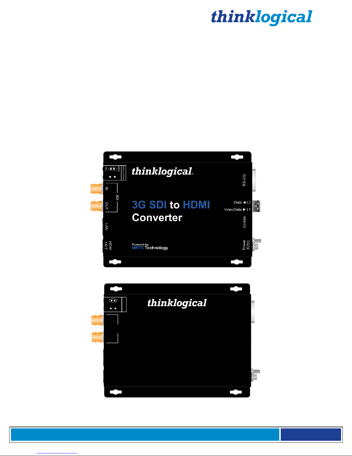
1.2. Product Overview
The Thinklogical® 3G SDI to HDMI Converter allows you to seamlessly convert a broadcast quality SDI
signal to HDMI. The unit is full SMPTE compliant, including the active loop out port.
3G SDI to HDMI Converter/Extender (SDC-000001-LC)
3G SDI to HDMI Converter (SDC-000001)
Page 6

®
3 G S D I t o H D M I C o n v e r t e r M a n u a l , R e v . D , A p r i l , 2 0 1 3
P a g e 6
2. System Features
2.1. General System Features
The Thinklogical® 3G SDI to HDMI Converter allows users to seamlessly convert a broadcast
quality SDI signal to HDMI. The 3G SDI to HDMI Converter is full SMPTE compliant,
including the active loop out port. The 3G SDI to HDMI Converter/Extender has a fiber
output that is fully compatible with our Velocity line of receivers as well as our VX routers for a
comprehensive conversion and extension solution. Not only does it convert and scale
video signals in real-time, it also provides the highest quality images for professional
audio-visual end users.
Each 3G SDI to HDMI Converter system includes the following features:
Conversion/Scaling:
Input: SD, HD, 3G SDI
Output: 1920x1200p60, 1080p50, 1080p60, 720p50, 720p60, 576p50, 480p60.
Fiber optic output compatible with Thinklogical Velocity® Receivers
SDI embedded audio conversion to HDMI output and compatible with Thinklogical Velocity
Receivers
User Control via RS-232 and Ethernet
SMPTE standards supported: 259M-C, 292, 424M, 425 level A and level B
Active SMPTE compliant loop out port
Automatic Video Input Detection
Additional manual resolution selection via push buttons
Video Processor Features:
Per pixel motion-adaptive video noise reduction- removes the white Gaussian noise present in
most types of video
Content adaptive block and mosquito noise reduction- significantly reduces the blocking and
mosquito noise artifacts present in compressed video
Advanced per-pixel, motion-adaptive, edge-adaptive 3D de-interlacing with support for arbitrary
film cadences- removes “jaggies” and “feathering” to produce smooth and clear images
Adaptive scaling- produces sharp and clean images and low or high resolutions
Natural dept expansion- enhances details and sensation of depth for greater realism and super
resolution effect
Adaptive contrast enhancement (ACE) brings out shadow detail without crushing mid-tones or
highlights
Intelligent color remapping (ICR) enables vivid color without hue shifts and clipping while
maintaining accurate flesh tone
Qdeo™ true color- a unique solution for using the full dynamic range of 10-bit and 12-bit
displays which eliminates contouring seen when viewing typical 8-bit consumer video
Page 7

®
3 G S D I t o H D M I C o n v e r t e r M a n u a l , R e v . D , A p r i l , 2 0 1 3
P a g e 7
2.2 Technical Specifications
Supported Frame Rate Formats: Progressive, Interlaced, PsF
Function
Video Standards Supported
Formats
SD-SDI
SMPTE 259M
PAL and NTSC
HD-SDI
SMPTE 292M
All standard HD-SDI compatible formats
3G SDI
SMPTE 424M, 425M, Level A and B
All SMPTE 425 level A and B compatible
formats
Storage Temperature
0 to 50 deg C , 5 – 95 % RH, non condensing
Power Supply Voltage
+5.0 VDC
DC Adapter
AC/DC adapter universal input 90-264 VAC
Power Consumption
With Velocity SFP: 9.5 Watts
Without Velocity SFP: 8.5 Watts
Operating Temperature and
Humidity
0 to 50 °C (32 to 122 °F); 5 to 95% RH, non-condensing
Enclosure Dimensions
Height: 1.1” (27.94 mm)
Depth: 7” (177.80 mm)
Width: 5.375" (136.65 mm)
Weight
Actual Weight: 1 lb (0.45 kg)
Shipping Weight: 9 lbs (4.08 kg)
Compliance
Pending approvals for US, Canada, and European Union
Page 8

®
3 G S D I t o H D M I C o n v e r t e r M a n u a l , R e v . D , A p r i l , 2 0 1 3
P a g e 8
3. Connections
HDMI/DVI OUT DDC
VEL-000M03-LCRX Receiver
HDMI/DVI OUT
USER’ S
MENU
L1
RS-232
HDMI/SDI
Display
Local SDI OUT
SDI Source
+5VDC
SDC-000001-LC
Fiber L1
(up to 1000 meters):
Data/Audio/Video Tx to Rx
Audio OUT
1
2 3 4
1 2 3 4 5 6 7
+5VDC
L1
3.1. Connecting the 3G SDI to HDMI Converter/Extender (SDC-000001-LC)
The 3G SDI to HDMI Converter/Extender (SDC-000001-LC) includes an SFP module with LC-type
fiber-optic cable ports to allow a connection to a remote device up to 1000 meters away. A 3G SDI
Source and local output display connect to the SDI IN & OUT ports with standard AES3, 75Ω BNC
cables. The HDMI OUT port connects to an HDMI/SDI display through a standard HDMI cable. An
RS-232 port is also available to connect a serial device. (See RS-232 pin-out guide, paragraph 3.3,
on page 9). To extend content to a remote receiver, use multi-mode fiber-optic cable (up to 1000’).
Fiber L1 carries data, audio and video from the Tx to the RX. Monitors or other viewing devices are
connect to the Velocity Receiver with HDMI/DVI cables.
The 3G SDI to HDMI Converter/Extender extending video/audio over fiber
to Thinklogical’s VelocityDVI-3AV+® Receiver
Page 9
®
3 G S D I t o H D M I C o n v e r t e r M a n u a l , R e v . D , A p r i l , 2 0 1 3
P a g e 9
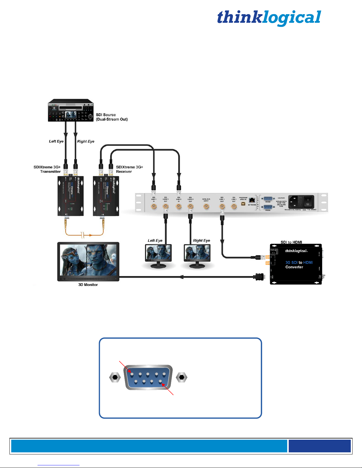
3.2 Connecting the 3G SDI to HDMI Converter (SDC-000001)
Thinklogical’s Image Evolution X3
Thinklogical’s Image Evolution X3 converts and scales
SD, HD, 3G (levels A & B) and Dual-Link HD-SDI
Pin 1 DCD_OUT
Pin 2 RX_IN
Pin 3 TX_OUT
Pin 4 DTR_IN
Pin 5 GND
Pin 6 DSR_IN
Pin 7 RTS_IN
Pin 8 CTS_OUT
Pin 9 RI_OUT
Pin 1
Pin 9
The 3G SDI to HDMI Converter can be used in a variety of applications, and with a variety of
other Thinklogical products, that do not require video or data extension across large
distances. A 3G SDI Source and local output display connect to the SDI IN & OUT ports with
standard AES3, 75Ω BNC cables. An RS-232 port is also available to connect a serial
device. (See RS-232 pin-out guide, paragraph 3.3, below).
The 3G SDI to HDMI Converter 3D Application using Thinklogical’s Image Evolution X3®
3.3 RS-232 Pin Out
Page 10
®
3 G S D I t o H D M I C o n v e r t e r M a n u a l , R e v . D , A p r i l , 2 0 1 3
P a g e 10
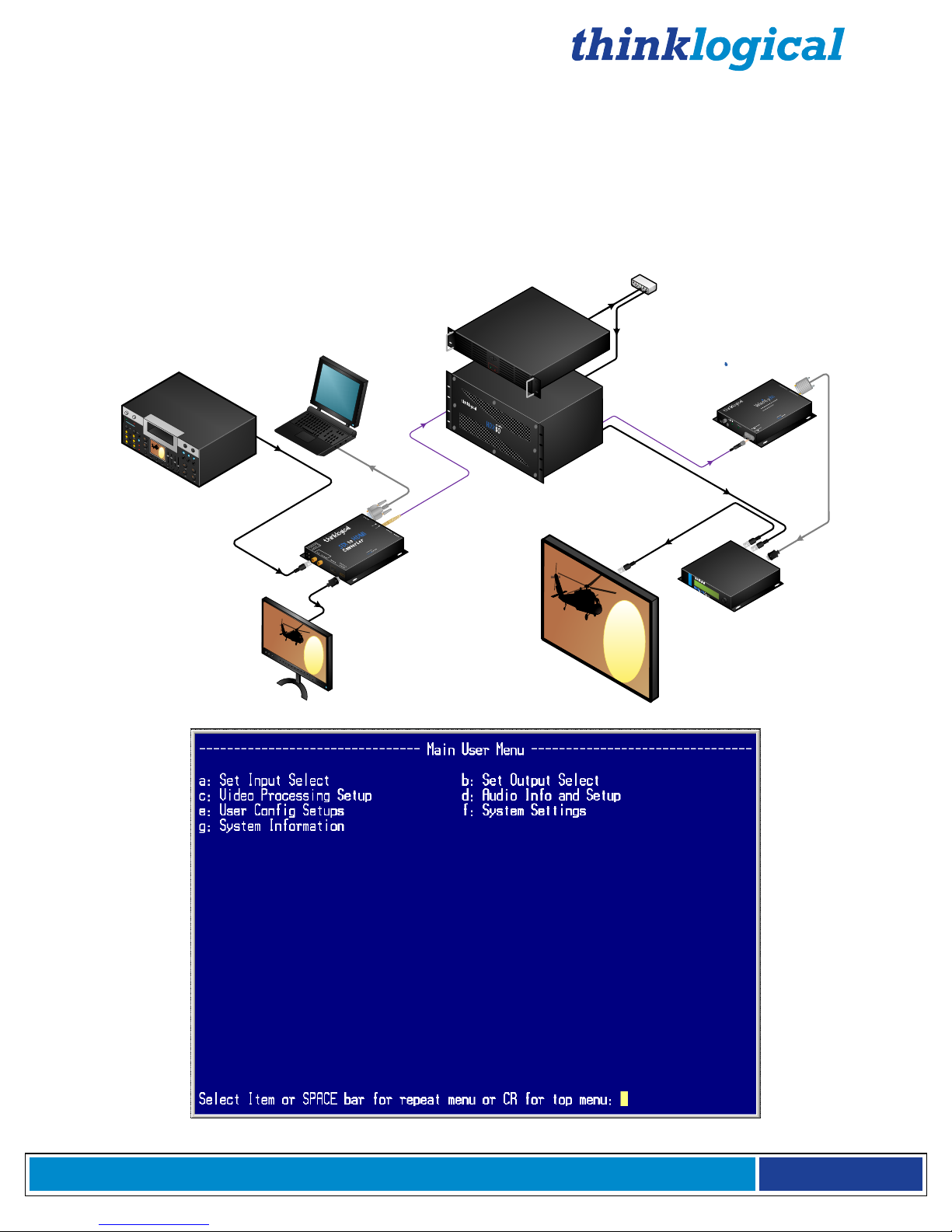
3.4 User Menu Configurations
3G SDI to HDMI
Converter
Velocitydvi-3
Receiver
RS
-
232
SDI
Source
SDI
IN
HDMI OUT
Local
HDMI
Display
Fiber Optic Cable
USER’ S
MENU
Network
Hub
HDX80 Router
HDMI to 3G SDI
Converter
SDI Monitor
Fiber Optic Cable
DVI to
HDMI cable
SDI
OUT
Gen Lock IN
Customer
Supplied
Computer
When connecting to a network, as in the diagram below, a user interface may be connected to the 3G
SDI to HDMI Converter’s RS-232 port with a standard serial cable. Thinklogical’s 3G SDI to HDMI
Converter, HDMI to 3G SDI Converter and Image Evolution X3 are all shipped with the IP address
192.168.75.200. (To change an IP address, go to SYSTEM SETTINGS ETHERNET
SETTINGSSET IP ADDRESS. See page 13.)
From the Main User Menu screen (below), follow the menus for system configuration.
Page 11

®
3 G S D I t o H D M I C o n v e r t e r M a n u a l , R e v . D , A p r i l , 2 0 1 3
P a g e 11
The RS-232 setup and configuration is as follows:
Use Hyperterm or similar type interface.
Baud rate is 115200, 8 bits, no parity, 1 stop bit, no flow control
Emulate VT-100 mode
MAIN USER MENU:
A: Set Input Select
B: Set Output Select
C: Video Processing Setup
D: Audio Info and Setup
E: User Config Setups
F: System Settings
G: System Information
MAIN MENU:
A: Set Input Select
Note: A valid input must be applied in order for the configuration to be used.
a: Single Link Input
This option forces a re-configure of the unit. A valid signal needs to be present.
b: Enable Loop Output
This will enable the video signal applied to input 1 to be looped back out of the IEX3.
This is enabled as default.
c: Disable Loop Output
Turns off the BNC Loop output 1.
d: AUTO mode ON
Detects when a video source has changed format. On cable insertion, the unit performs
a re-configuration of the last known output setting with the new input.
e: AUTO Mode OFF
Turns off the AUTO mode.
MAIN MENU:
B: Set Output Select
Sets the output video resolution. A valid input video signal needs to be present.
a: 480p @ 60
b: 576p @ 50
c: 720p @ 50
d: 720p @ 60
e: 1080p @ 50
f: 1080p @ 60 (default)
MAIN MENU:
C: Video Processing Setup
a: Comp. Artifact Reducer
Selects menu for Component Artifact Reducer (CAR) video processing functions.
Page 12

®
3 G S D I t o H D M I C o n v e r t e r M a n u a l , R e v . D , A p r i l , 2 0 1 3
P a g e 12
b: DeInterlacer
Selects the menus for the DeInterlacer (DEINT) video processing functions.
c: Noise Reducer
Selects the menus for the Noise Reduction (NR) video processing functions.
d: Picture Control
Selects the menus for Picture Control (PC) video processing functions.
e: Edge Enhancer
Selects the menus for Edge Enhancement (EE) video processing functions.
f: Color Management Unit
Selects menus for Color Management Unit (CMU) video processing functions.
g: Adapt. Contrast Enhancer
Selects the menus for the Adaptive Contrast Enhancer (ACE) video processing
functions.
h: 3D Control Menu
Selects the menu for output 3D processing formats.
MAIN MENU:
D: Audio Info and Setup
a: Enable Audio Output
Enables the embedded audio output from the selected input.
b: Disable Audio Output
Mutes all embedded audio output channels.
c: Get Audio Info Input
Get Audio information from BNC Input.
d: Set Audio Delay
Audio Delay range is from -50 - +50 in mS with the default being 0.
e: Get Audio Delay
The programmed Audio Delay in mS.
f: Get Audio Channel Cfg.
Get the audio channel mapping.
g: Assign Audio Channels
Configure input to output channel configuration.
MAIN MENU:
E: User Config Setups
a: Save Current Config
Saves the current system settings to the non-volatile Memory. Maximum of 20
characters for the record name.
b: Set Power On Config
This option will set the current configuration to the user in an accessible region of flash.
This configuration is restored during power up.
c: Restore Config Record
Recall any one of the current saved configuration records.
d: Restore Factory Config
Page 13

®
3 G S D I t o H D M I C o n v e r t e r M a n u a l , R e v . D , A p r i l , 2 0 1 3
P a g e 13
This selection will delete the stored power on configuration and will re-configure to the
factory default on the next power cycle (1080i @ 60 Hz).
e: Erase Record(s)
Erase a particular record or all records.
MAIN MENU:
F: System Settings
a: Ethernet Settings
Settings for the network interface.
Default Settings:
IP Address - 192.168.75.200
Mask - 255.255.255.0
Gateway - 0.0.0.0
Note: To change the IP address of a device: From the SYSTEM MENU, go to ETHERNET
SETTINGS, then to SET IP ADDRESS.
b: Enable HDMI Output Video Mode
Enables the HDMI output to be in true HDMI mode.
c: Enable DVI Output Video Mode
Enable this option if the sink device is a true DVI monitor/projector.
NOTE: If output appears to be noisy, enable DVI Output Video Mode. HDMI mode carries
video along with audio information. Choose this mode for video-only applications.
d: Get Video Mode
This will return current video mode.
MAIN MENU:
G: System Information
The following is used for retrieving information regarding current setup and signal detection
information.
a: Get Software Version
Displays the System’s software version number.
b: Get FPGA Version
Displays FPGA 1 version number
c: Get Linux Version
Displays version of software currently running on ethernet interface.
d: Get Local Temperature
Displays the temperature inside the box
e: Get Input Info
Displays Information about the video and embedded audio signal on BNC Input 1
f: Get Output Info
Displays Information about the video and embedded audio signal on BNC
Outputs
Page 14

®
3 G S D I t o H D M I C o n v e r t e r M a n u a l , R e v . D , A p r i l , 2 0 1 3
P a g e 14
MAIN MENU:
C: Video Processing Setup
SUB-MENU:
a: Comp. Artifact Reducer
This feature is used to reduce compression artifacts that are caused by video compression
schemes such as MPEG2. Mostly used on YCbCr 4:2:2 interlaced or progressive input video.
a: Comp. Arti. Reducer EN
Enables the Compression Artifact Reducer.
b: Mosq. Noise Reducer EN
Enables the Mosquito (Ringing) Noise Reducer.
c: Block Noise Reducer EN
Enables the Block (8x8) Noise Reducer.
d: Non Std Block Noise Det EN
Enables the Non-Standard Block Detection.
e: Enable All CAR Blocks
Enables All the above (A,B,C,D) Noise Reduction Blocks.
f: Disable All CAR Blocks
Disables All the Noise Reduction Blocks.
MAIN MENU:
C: Video Processing Setup
SUB-MENU:
b: DeInterlacer
Selects the menu for the DeInterlacer (DEINT) video processing functions.
a: Deinterlacer BYPASS
Bypasses the deinterlacer (input is progressive).
b: Deint 2D VECTOR
Sets the Interlacer for 2D Vector mode (Interlaced input DEFAULT mode).
c: Deint 2D VECTOR AGGRES.
Sets the Interlacer for 2D Aggressive mode (Interlaced input).
d: Deint 3D FIXED
Sets the Interlacer for 3D fixed mode (Interlaced input).
e: Deint 3D Mo Adpt Vector
Sets the Interlacer for 3D Motion Adaptive Vector mode.
f: Deint 3D MA Vect Aggres
Sets the Interlacer for 3D Motion Adaptive Vector Aggressive mode.
g: Deint 3D MA Vect Linear
Sets the Interlacer for 3D Motion Adaptive Vector Linear mode.
h: DEINTERLACER DEFAULT
Sets the Interlacer for DEFAULT mode.
MAIN MENU:
C: Video Processing Setup
SUB-MENU:
c: Noise Reducer
Page 15

®
3 G S D I t o H D M I C o n v e r t e r M a n u a l , R e v . D , A p r i l , 2 0 1 3
P a g e 1 5
Selects the menus for the Video Noise Reduction (NR) video processing functions.
Used mostly on YCbCr 4:2:2 Input video.
a: Noise Reducer DISABLE
Disables the Noise Reduction block.
b: Noise Reducer 2D
Sets the Noise Reducer for 2D (Spatial) mode.
c: Noise Reducer 3D Fixed
Sets the Noise Reducer for 3D Fixed (Temporal) mode.
d: Noise Reducer 3D Adapt
Sets the Noise Reducer for 3D Adaptive (Temporal) mode.
e: Noise Reducer Default
Sets the Noise Reducer for Default mode.
f: Noise Reducer Automatic
Sets the Noise Reducer for Automatic mode.
MAIN MENU:
C: Video Processing Setup
SUB-MENU:
d: Picture Control
a: Set All Levels Default
Restores Contrast, Brightness, Tint, Black, Color Temp levels to defaults.
b: Set Contrast Level
Enter the Contrast Level 0 to +10. The Default value is 10.
c: Set Brightness Level
Enter the Brightness Level -100 to +100. The Default value is 0.
d: Set Tint Level
Enter the Tint Level -180 to +180. The Default value is 5.
e: Set Black Level
Enter the Black Level 0 to +100. The Default value is 0.
f: Set Color Temperature
SUB MENU : Video Set Color Temperature Menu
a: Color Temperature NORMAL
Sets the color temp to 6500.
b: Set Color Temperature COOL
Sets the color temp to 8000.
c: Color Temperature WARM
Sets the color temp to 6000.
d: Color Temperature CUSTOM
Enter Color Temp Level 6000 to 8000 (Normal = 6500)
MAIN MENU:
C: Video Processing Setup
SUB-MENU:
e: Edge Enhancer
Selects the menus for Edge Enhancement (EE) video processing functions.
Page 16

®
3 G S D I t o H D M I C o n v e r t e r M a n u a l , R e v . D , A p r i l , 2 0 1 3
P a g e 16
a: Edge Enhancer OFF
b: Edge Enhancer LOW
c: Edge Enhancer MED
d: Edge Enhancer HIGH
MAIN MENU:
C: Video Processing Setup
SUB-MENU:
f: Color Management Unit
Selects the menus for Color Management Unit (CMU) video processing functions.
a: Hue Saturation Menu
Video Hue Saturation Menu
a: Hue Saturation ENABLE
b: Hue Saturation DISABLE
c: Intelligent Saturation ENABLE
d: Intelligent Saturation DISABLE
e: Set HUE Saturation Level
f: Set HUE Global Sat. Level
g: ICR Advanced Menu
Note: Hue saturation needs to be enabled (selection ‘a’) in order for ‘Set HUE Saturation
b: Qdeo True Color Menu
Level’ (selection ‘e’) to be valid.
Video Qdeo Menu
a: Qdeo True Color OFF
b: Qdeo True Color SOFT
c: Qdeo True Color GENTILE
d: Qdeo True Color MEDIUM
e: Qdeo True Color HIGH
c: Film Grain Gain Menu
Video Film Grain Gain MENU
a: Disable Film Grain Gain
b: Set Film Grain Gain
Range is 0 - 255. Default is 0.
c: Set FGG Temporal Freq.
Range is 0 - 255. Default is 0.
d: Flesh Tone Correction
a: Set FTDC Preset Enable
b: Set FTDC Preset Level 1
c: Set FTDC Preset Level 2
d: Set FTDC Preset Level 3
e: Set FTDC Preset Level 4
f: Set FTDC Preset Level 5
g: Set FTDC Preset Level 6
h: Set FTDC Preset Disable
e: Set GAMMA Menu
a: GAMMA Disable
b: GAMMA 1.8
c: GAMMA 2.5
Page 17

®
3 G S D I t o H D M I C o n v e r t e r M a n u a l , R e v . D , A p r i l , 2 0 1 3
P a g e 17
d: GAMMA S-Curve Light
e: GAMMA S-Curve Dark
MAIN MENU:
C: Video Processing Setup
SUB-MENU:
g: Adapt. Contrast Enhancer
Selects the menus for Adaptive Contrast Enhancer (ACE) video processing functions.
a: ACE PRESET OFF
b: ACE PRESET LOW
c: ACE PRESET MEDIUM
d: ACE PRESET HIGH
e: ACE PRESET RANGE 0-255
f: ACE PRESET RANGE 16-235
g: ACE Brightness Menu
a: Brightness DISABLE
b: Brightness DEFAULT
c: Brightness Taper Size
Enter Taper Size (16, 32, 64, 128, 256, 512).
d: Brightness Taper Side
Enter Taper Side Select (1,2).
e: Brightness Enhancement
Enter Enhancement Level (1 - 15).
f: Brightness Threshold 1
Enter Threshold 1 Level (0 - 1023).
g: Brightness Threshold 2
Enter Threshold 2 Level (0 - 1023).
MAIN MENU:
C: Video Processing Setup
SUB-MENU:
h: 3D Control Menu
a: Left/Right Frame Menu
Menu to functions that will allow the zooming in of an incoming 3D side-
by-side signal and display one half as a 2D image (left eye or right eye).
b: Line-By-Line Output Menu
Select output format of a line-by-line signal.
c: Disable Line-By-Line Output
Turns off the line-by-line feature.
d: Side-By-Side Output Menu
Select output format of a side-by-side signal.
e: Disable Side-By-Side Output
Turns off the side-by-side feature.
f: Dual Stream Output Menu Select output format of a dual stream signal.
g: Enable Adaptive Clock Factory Use.
h: Disable Enable Adaptive Clock Factory Use.
Page 18

®
3 G S D I t o H D M I C o n v e r t e r M a n u a l , R e v . D , A p r i l , 2 0 1 3
P a g e 18
4. Regulatory & Safety Compliance
4.1. Symbols Found on Our Products
Markings and labels on our products follow industry-standard conventions. Regulatory markings found
on our products comply with domestic and many international requirements.
4.2 Regulatory Compliance
Thinklogical® products are designed and made in the U.S.A. Products have been tested by a nationally
recognized testing laboratory and found to be compliant with the following standards (both domestic
USA and many international locations).
North America
These products comply with the following standards:
Safety
ANSI/UL60950-1: 1st Edition (2003)
CAN/CSA C22.2 No. 60950-1-03
LASER Safety
CDRH 21CFR 1040.10
Class 1 LASER Product
Electromagnetic Interference
FCC CFR47, Part 15, Class A
Industry Canada ICES-003 Issue 2, Revision 1
Australia & New Zealand
This is a Class A product. In a domestic environment this product may cause radio interference, in
which case the user may be required to take adequate measures.
European Union
Declaration of Conformity
Manufacturer’s Name & Address: Thinklogical, LLC®
100 Washington Street
Milford, Connecticut 06460 USA
Telephone: 1-203-647-8700
Product Name
Models: 3GSDI to HDMI Converter, 3GSDI to HDMI Converter/Extender
These products comply with the requirements of the Low Voltage Directive 72/23/EEC and the EMC
Directive 89/336/EEC.
4.3. Standards with Which Our Products Comply
Safety
CENELEC EN 60950-1, (2006)
LASER Safety
IEC60825:2001 Parts 1 and 2
Class 1 LASER Product
Page 19

®
3 G S D I t o H D M I C o n v e r t e r M a n u a l , R e v . D , A p r i l , 2 0 1 3
P a g e 19
Electromagnetic Emissions
EN55022: 1994 (IEC/CSPIR22: 1993)
EN61000-3-2/A14: 2000
EN61000-3-3: 1994
Electromagnetic Immunity
EN55024: 1998 Information Technology Equipment-Immunity Characteristics
EN61000-4-2: 1995 Electro-Static Discharge Test
EN61000-4-3: 1996 Radiated Immunity Field Test
EN61000-4-4: 1995 Electrical Fast Transient Test
EN61000-4-5: 1995 Power Supply Surge Test
EN61000-4-6: 1996 Conducted Immunity Test
EN61000-4-8: 1993 Magnetic Field Test
EN61000-4-11: 1994 Voltage Dips & Interrupts Test
4.4. Supplementary Information
The following statements may be appropriate for certain geographical regions and might not apply to
your location.
This Class A digital apparatus meets all requirements of the Canadian Interference-Causing
Equipment Regulations.
Cet appareil numérique de la classe A respecte toutes les exigencies du Règlement sur le
matérial brouilleur du Canada.
Warning! This is a Class A product. In a domestic environment, this product may cause
radio interference, in which case the user may be required to take adequate corrective
measures.
Note: This equipment has been tested and found to comply with the limits for a Class A
digital device, pursuant to part 15 of the FCC Rules. These limits are designed to provide
reasonable protection against harmful interference when the equipment is operated in a
commercial environment. This equipment generates, uses and can radiate radio
frequency energy and, if not installed and used in accordance with the instruction
manual, may cause harmful interference to radio communications in which case the user
may be required to take adequate corrective measures at their own expense.
Note: This Class A digital apparatus complies with Canadian ICES-003 and has been
verified as being compliant within the Class A limits of the FCC Radio Frequency Device
Rules (FCC Title 47, Part 15, Subpart B CLASS 1), measured to CISPR 22: 1993 limits and
methods of measurement of Radio Disturbance Characteristics of Information
Technology Equipment.
Note:
electromagnetic fields
Note:
may be needed to comply with Immunity Requirements
The user may notice degraded audio performance in the presence of
.
If using a keyboard that is noise susceptible, a ferrite ring on the keyboard cable
Page 20

®
3 G S D I t o H D M I C o n v e r t e r M a n u a l , R e v . D , A p r i l , 2 0 1 3
P a g e 20
4.5. Product Serial Number
Thank you for choosing Thinklogical® products for your application.
We appreciate your business and are dedicated to helping you successfully use our products.
is always here to help you.
To contact us, please use the following telephone numbers and internet-based methods:
®
Thinklogical® products have a unique serial number printed on an adhesive label that is fixed to the
bottom of the chassis. The serial number includes a date-code. The format for the date-code is 2 digits
for the week, 2 digits for the year, plus two or three digits for a unique unit number. This serial number
is also found on the original shipping carton.
4.6. Connection to the Product
Connections and installation hardware for our products use industry-standard devices and methods. All
wiring connections to the customer equipment are designed to minimize proprietary or customized
connectors and cabling. Power connections are made with regionally appropriate power cords and
approved methods.
5. Thinklogical® Support
5.1. Customer Support
Thinklogical® is an engineering company and you will receive any information you
require directly from our most knowledgeable engineers. We believe that the first lines
of support are design engineers that developed each particular product. Therefore, your
questions will be handled promptly by our in-house engineers who are most familiar
with your products.
5.1.1. Website
Check out our website for current product offerings, support information and general
information about all of the products we offer.
Our internet website offers product information on all current systems, including technical
specification sheets and installation guides (for viewing online or for download), product
diagrams showing physical connections and other information you might need.
Internet: www.thinklogical.com
Note: Most online documents are stored as Adobe Acrobat “PDF” files. If you do
not have the Adobe Acrobat reader needed to view PDF files, visit www.adobe.com
for a download.
5.1.2. Email
Thinklogical® is staffed Monday through Friday from 8:30am to 5:00pm, Eastern Time Zone.
We will do our best to respond to your email inquiries promptly. Please use one of the
following email addresses:
Page 21

®
3 G S D I t o H D M I C o n v e r t e r M a n u a l , R e v . D , A p r i l , 2 0 1 3
P a g e 21
info@thinklogical.com – Information on Thinklogical® and our products.
sales@thinklogical.com – Sales Department - orders, questions or issues.
support@thinklogical.com – Product support, technical issues or questions, product
repairs and request for Return Authorization.
5.1.3. Telephone
Sales: Please contact our expert sales staff in Milford, CT at 1-203-647-8700 or, if in the
continental U.S., use our toll-free number 1-800-291-3211. We are here Monday through
Friday from 8:30am to 5:00pm, Eastern Time Zone. Ask a sales rep for a direct dial phone
number when you call.
Product Support: Contact Product Support in Milford, Connecticut at 1-203-647-8700. The
support lines are manned Monday through Friday, 8:30am to 5:00pm, Eastern Time Zone.
International Sales: Please contact our U.S. sales staff in Milford, CT at 1-203-647-8700.
We are here Monday through Friday, 8:30am to 5:00pm, Eastern Time Zone (same as New
York City). If leaving a voice message, please provide a preferred time to call back so we may
reach you at your convenience.
Our switchboard attendant will direct your call during regular business hours. We have an
automated attendant answering our main telephone switchboard after regular business hours
and holidays. You may leave voice messages for individuals at any time. Our Sales
Representatives have direct numbers to facilitate your next call to us.
5.1.4. Fax
Our company facsimile number is 1-203-783-9949. Please indicate the nature of the fax on
your cover sheet and provide return contact information.
5.2 Product Support
Thinklogical’s® support personnel are available Monday through Friday from 8:30am to
5:00pm, Eastern Time Zone. If your application might require assistance at some time outside
of our normal business hours, please contact us beforehand and we will do our best to make
arrangements to help you with your Thinklogical® products.
5.2.1. Warranty
Thinklogical® warrants this product against defects in materials and workmanship for a period
of one year from the date of delivery. Thinklogical® and its suppliers disclaim any and all other
warranties.
Note: Thinklogical® Inc. products carry a one year warranty, with longer term
available at time of purchase on most products. Please refer to your product
invoice for your products Warranty Terms & Conditions.
Defect remedy shall be, repair or replacement of the product, provided that the defective
product is returned to the authorized dealer within a year from the date of delivery.
If you wish to return your device, contact the Thinklogical® authorized dealer where you
purchased the device, or if you purchased directly, call Thinklogical at 1-800-291-3211 (USA).
Page 22

®
3 G S D I t o H D M I C o n v e r t e r M a n u a l , R e v . D , A p r i l , 2 0 1 3
P a g e 22
5.2.2. Return Authorization
If you have any issue with any Thinklogical product, have product questions or need technical
assistance with your Thinklogical system, please contact Customer Support at 1-800-291-
3211 (USA only) or 1-203-647-8700 and let us help.
If you must return a product to Thinklogical® directly, Customer Support will ask you to
describe the problem and will issue you a Return Merchandise Authorization number (RMA#).
Pack the device in its original box, if possible, and return it with the RMA# on the box.
Note: Do not return a product to Thinklogical® without a Return Material
Authorization Number.
Return address for products with Return Material Authorization:
Thinklogical, LLC®
Attn: RMA#
100 Washington Street
Milford, CT 06460 USA
PH: 800-291-3211 (USA only)
Page 23

®
3 G S D I t o H D M I C o n v e r t e r M a n u a l , R e v . D , A p r i l , 2 0 1 3
P a g e 23
Appendix A- Application Diagrams
3G SDI to HDMI
Converter
Velocitydvi-3
Receiver
RS
-
232
SDI
Source
SDI
IN
HDMI OUT
Local
HDMI
Display
Fiber Optic Cable
USER’ S
MENU
Network
Hub
HDX80 Router
HDMI to 3G SDI
Converter
SDI Monitor
Fiber Optic Cable
DVI to
HDMI cable
SDI
OUT
Gen Lock IN
Customer
Supplied
Computer
Thinklogical® conversion application using a 3G SDI to HDMI Converter with fiber extension, HDX80
Router, VelocityDVI-3AV+ Receiver and HDMI to SDI Converter.
Page 24

®
3 G S D I t o H D M I C o n v e r t e r M a n u a l , R e v . D , A p r i l , 2 0 1 3
P a g e 24
RS
-
232
HDMI/DVI
Source
SDI
OUT
HDMI
/DVI
IN
USER’ S
MENU
Network
Hub
Customer
Supplied
Computer
HDX80 Router
HDMI Monitor
HDMI
OUT
SDI
OUT
3G SDI to HDMI
Converter
HDMI to 3G SDI
Converter
SDI Monitor
SDI
IN
BNC co
-
ax
BNC co
-
ax
Thinklogical® conversion application using an HDMI to 3G SDI Converter, HDX80 Router and 3G SDI
to HDMI Converter
Page 25

®
3 G S D I t o H D M I C o n v e r t e r M a n u a l , R e v . D , A p r i l , 2 0 1 3
P a g e 25
SDIXtreme 3G+
Receiver
RS
-
232
HDMI/DVI
Source
SDI
OUT
HDMI
/DVI
IN
USER’ S
MENU
Network
Hub
Customer
Supplied
Computer
HDX80 Router
HDMI Monitor
Pan/Tilt/Zoom
Controller
HDMI
OUT
3G SDI to HDMI
Converter
HDMI to 3G SDI
Converter
SDI Monitor
Fiber Optic Cables
Fiber Optic Cables
RS
-
422
SDI
IN
RS
-
422
Thinklogical® conversion application using an HDMI to 3G SDI Converter with fiber output, HDX80
Router, SDI 3G+ Receiver and 3G SDI to HDMI Converter.
Page 26

®
3 G S D I t o H D M I C o n v e r t e r M a n u a l , R e v . D , A p r i l , 2 0 1 3
P a g e 26
Appendix B- Quick Start Guide
External Control CPU
Network Hub
STEP 8: Connect the Controller
Cards’ LAN Ports to your Controller
CPU with CAT5 cables. (CPU IP
address: 192.168.13.9) The standard
IP address for the 3G SDI to HDMI
Converter is 192.168.75.200
Optional Secondary Controller Card
IP address: 192.168.13.16
Primary Controller Card
IP Address: 192.168.13.15
STEP 1: Connect the Velocity Receiver to the VX80
using a multi-mode fiber-optic cable (up to 1000 meters).
Connect fiber L1 to any Downstream Transmit Port.
STEP 3: Connect a monitor to the VelocityDVI-3 Receiver’s DVI
OUT port with a standard HDMI/DVI cable. A second, non-DDC
monitor may also be connected to the Receiver's DVI to Display port.
Connect an Audio OUT device with a standard cable as shown.
9
STEP 4: Connect your 3G SDI to HDMI Converter to the VX80 using a
multi-mode fiber-optic cable (up to 1000 meters). Connect fiber L1 to any
Upstream Receive Port.
HDMI/DVI OUT DDC
1
STEP 2: Install the VelocityDVI-
3AV+ Receiver’s +5VDC adapter
(PWR-000022-R) and plug it into a
standard AC source.
2
3
STEP 6: Connect the SDI IN cables from the SDI Source to the 3G SDI to
HDMI Converter’s SDI IN Port. Connect an optional Local Monitor to the
SDI OUT Port. Connect a Serial device to the RS-232 RJ45 Port.
STEP 7:
Connect an
HDMI/SDI
Display to the
HDMI/SDI
OUT Port.
VEL-AV0M03-LCRX Receiver
L1
8
HDMI/DVI OUT
USER’ S
MENU
L1
RS-232
HDMI/SDI
Display
Local
SDI
OUT
SDI Source
+5VDC
VX80 Router
Complete steps 1 through 9 to connect your Thinklogical 3G SDI to HDMI Converter
3G SDI to HDMI Converter
4
5
6
7
SDC-000001-LC
STEP 5: Install the 3G SDI to HDMI Converter’s +5VDC adapter (PWR-
000022-R) and plug it into a standard AC source.
STEP 9: Connect both supplied AC Power Cords
(PWR-0000006-R) to the receptacles located on the
VX80's power supplies. Plug each one into a standard
AC source. Verify that all system functions are
operating properly.
QUICK-START GUIDE
QUICK-START GUIDE
Thinklogical’s® 3G SDI to HDMI Converter
and VelocityDVI-3 Fiber Extension Systems
as used with the VX80 KVM Matrix Switch
Thinklogical’s® 3G SDI to HDMI Converter
and VelocityDVI-3 Fiber Extension Systems
as used with the VX80 KVM Matrix Switch
3G SDI_to_HDMI_Converter_VX80_VEL-3_QSG_Manual
Audio OUT
1
2 3 4
1 2 3 4 5 6 7
Page 27

®
3 G S D I t o H D M I C o n v e r t e r M a n u a l , R e v . D , A p r i l , 2 0 1 3
P a g e 27
APPENDIX C: GUI
The Graphical User Interface (GUI) for the 3G SDI to HDMI Converter was developed to easily create,
set and recall custom configurations. There are 6 main menus that allow you to configure the
Input/Output, Video Processor, Audio, User Configurations, Xtreme 3G and System Information.
There are sub-menus under the video processor menu for Video Control and Picture Control.
Note: When power has been cycled on a unit it will reset to factory settings unless the “Set
Power On Config” has been set in the User Menu.
Input/Output Menu
This menu allows you to select the input and the format of the output. By clicking the “Take” button at
the bottom of the screen you are able to commit the output format that you have selected.
Page 28

®
3 G S D I t o H D M I C o n v e r t e r M a n u a l , R e v . D , A p r i l , 2 0 1 3
P a g e 28
Video Processor > Video Control
The Video Control sub-menu allows you to control DeInterlacer, Noise Reducer, Compression Artifact
Reducer, Edge Enhancer, and Adaptive Contrast Enhancer.
Page 29

®
3 G S D I t o H D M I C o n v e r t e r M a n u a l , R e v . D , A p r i l , 2 0 1 3
P a g e 29
Video Processor > Picture Control
The Picture Control sub-menu allows you to control Hue Saturation, Advanced Color Remapping, Flesh
Tone Correction and Color Temperature. You can also reset all levels back to the factory default.
Page 30

®
3 G S D I t o H D M I C o n v e r t e r M a n u a l , R e v . D , A p r i l , 2 0 1 3
P a g e 30
Audio
The Audio menu allows you to select which output audio channel is sourced with any input audio
channel. It also allows you to enter an audio delay (from -50 ms to +50 ms) when needed.
Page 31

®
3 G S D I t o H D M I C o n v e r t e r M a n u a l , R e v . D , A p r i l , 2 0 1 3
P a g e 31
User
The User menu allows you to save your current configuration by name or restore factory configuration.
You can also use the drop down menu to “Select Config Name” and set power on configuration (which
sets the current configuration to be the default power on configuration), restore factory configuration
and delete the selected configuration.
Page 32

®
3 G S D I t o H D M I C o n v e r t e r M a n u a l , R e v . D , A p r i l , 2 0 1 3
P a g e 32
Fiber Link
The Fiber Link menu is valid only if the Optical Module Option is installed. This menu allows you to
view the Thinklogical Velocity Module and SFP information of the unit in use.
Page 33

®
3 G S D I t o H D M I C o n v e r t e r M a n u a l , R e v . D , A p r i l , 2 0 1 3
P a g e 33
System Info
The System Info menu allows you to view information for the inputs and outputs as well as Genlock and
software and firmware versions.
 Loading...