

Page 1
Remotely Controlled Power Switch Solutions
PDU4/4 AC Power Distribution Unit
PRODUCT MANUAL
AC POWER
DISTRIBUTION
Thinklogical, LLC®
100 Washington Street
Milford, Connecticut 06460 U.S.A.
Telephone: 1-203-647-8700
Fax: 1-203-783-9949
www.thinklogical.com
[Type text]
Page 2

®
PDU 4/4 Product Manual September, 2014
Page 1
PDU 4/4
®
Copyright Notice
Copyright © 2014. All rights reserved. Printed in the U.S.A.
Thinklogical, LLC®
100 Washington Street
Milford, Connecticut 06460 U.S.A.
Telephone: 1-203-647-8700
All trademarks and service marks are property of their respective owners.
Subject: PDU 4/4 AC Power Distribution Unit Product Manual
Release Date: September, 2014
Page 3

®
PDU 4/4 Product Manual September, 2014
Page 2
Table of Contents
PREFACE .............................................................................................................................................. 3
About Thinklogical ................................................................................................................................. 3
Note and Warning Symbols ................................................................................................................... 4
INTRODUCTION ......................................................................................................................... 4
Product Overview: The PDU4/4 ............................................................................................................ 4
1: THE PDU 4/4 AC POWER DISTRIBUTION UNIT ...................................................................... 5
Mounting The PDU 4/4 ................................................................................................................. 5
Front Panel LCD and Buttons ............................................................................................................... 6
Convection Cooling ............................................................................................................................... 6
Connecting the PDU 4/4 ........................................................................................................................ 6
The Rear Panel ..................................................................................................................................... 7
Power Connections ............................................................................................................................... 7
Domestic ............................................................................................................................................ 7
International ....................................................................................................................................... 7
Status LEDs ........................................................................................................................................... 7
USB Firmware Upgrade Ports ............................................................................................................... 7
Serial Interface ...................................................................................................................................... 7
Installation .............................................................................................................................................. 8
Port Setting Your Terminal Device ................................................................................................... 8
Cascading the PDU Chassis ............................................................................................................ 8
Box IDs .............................................................................................................................................. 8
Program Storage ............................................................................................................................... 9
Communicating with The PDU 4/4 ................................................................................................... 9
Programming Access ........................................................................................................................ 9
Log In ................................................................................................................................................ 9
Commands ............................................................................................................................................ 9
PDU 4/4 Technical Specifications ....................................................................................................... 15
PDU Models Available From Thinklogical ...................................................................................... 15
2: REGULATORY & SAFETY REQUIREMENTS ........................................................................ 15
Symbols Found On Our Products ................................................................................................... 15
Regulatory Compliance .................................................................................................................. 15
North America ................................................................................................................................. 16
Australia & New Zealand ................................................................................................................ 16
European Union .............................................................................................................................. 16
Standards with Which Our Products Comply ................................................................................. 16
Supplementary Information ................................................................................................................. 17
Product Serial Number ........................................................................................................................ 17
Connection to the Product ................................................................................................................... 17
3: THINKLOGICAL SUPPORT .................................................................................................. 18
Customer Support ............................................................................................................................... 18
Website ........................................................................................................................................... 18
Email ............................................................................................................................................... 18
Telephone ....................................................................................................................................... 18
Fax .................................................................................................................................................. 19
Product Support ................................................................................................................................... 19
Warranty ................................................................................................................................ ... 19
Return Authorization ....................................................................................................................... 19
APPENDIX A: PDU 4/4 QUICK START GUIDE .......................................................................... 20
Page 4

®
PDU 4/4 Product Manual September, 2014
Page 3
Preface
Thinklogical, LLC®
100 Washington St.
Milford, CT 06460
We, the Thinklogical team, are committed to understanding and
exceeding our customers’ requirements, the first time and every time.
About Thinklogical
Thinklogical is the leading manufacturer and provider of fiber optic KVM, video, audio, and peripheral
extension and switching solutions used in video-rich, big-data computing environments.
Thinklogical offers the only fiber optic KVM matrix switches and routers in the world
that are accredited to The Common Criteria, EAL4 and TEMPEST.
Governments, entertainment, scientific and industrial customers worldwide rely on Thinklogical’s products
and solutions for security, high performance, continuous operation and ease of integration. Thinklogical
products are designed and manufactured in the USA and are certified to the ISO 9001-2008 standard.
Thinklogical is headquartered in Milford, Connecticut and is privately held by Riverside Partners, LLC,
Boston, MA (http://www.riversidepartners.com). For more information about Thinklogical products and
services, please visit www.thinklogical.com.
Follow Thinklogical on LinkedIn at http://www.linkedin.com/company/thinklogical and on Facebook at
http://www.facebook.com/ThinklogicalUSA
Page 5
®
PDU 4/4 Product Manual September, 2014
Page 4
Note and Warning Symbols
BEFORE STARTING ANY PROCEDURE, IT IS RECOMMENDED
THAT YOU READ THE INSTRUCTIONS THOROUGHLY!
PDU 4/4 International AC (PDU-000003)
PDU 4/4 Domestic AC (PDU-000001)
Throughout this document you will notice certain symbols that bring your attention to important information.
These are Notes and Warnings. Examples are shown below.
Note: Important Notes appear in blue text preceded by a yellow exclamation point symbol, as
shown here.
A note is meant to call the reader’s attention to helpful information at a point in the text that is relevant to the
subject being discussed.
Warning! All Warnings appear in red text, followed by blue text, and preceded by a red stop
sign, as shown here.
A warning is meant to call the reader’s attention to critical information at a point in the text that is relevant to the
subject being discussed.
Introduction
Product Overview: The PDU 4/4
Thinklogical’s® PDU 4/4 Power Distribution Unit is an AC Power Switch that
remotely controls the power to eight separate devices per unit.
Eight individually-controlled AC power outlets may be switched off and on as desired.
Communicates with its control terminal using a serial interface.
Each PDU 4/4 has two banks of four outlets. Each individual outlet switches a maximum
of 10 Amperes. Each bank is rated at 15 Amperes total.
Designed for rack mounting (1U) or desktop use
Available in both domestic and international models
Features redundant DC power supplies for built-in I/O and control circuits
Individually programmable Reboot Time Delay on each outlet
Solid state zero-crossing relays to minimize power spikes
Easily expandable, cascading configuration
Password Security
Front panel LCD for easy system set up and configuration
Current monitoring of each port
Software updates available at ftp.thinklogical.com
Page 6
®
PDU 4/4 Product Manual September, 2014
Page 5
Thinklogical’s easy to use PDU 4/4 Power Distribution Unit is an AC Power Switch that remotely controls the
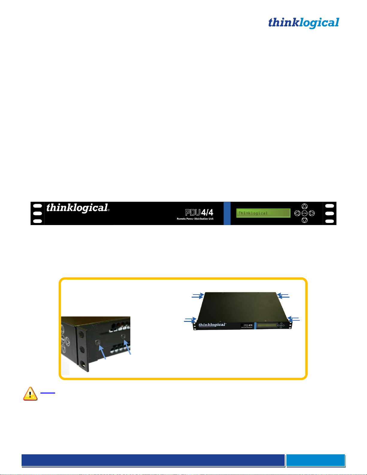
8 Mounting
Bracket Screws
2 Mounting bracket
screws in four places.
RACK-MOUNT OR DESK-TOP OPTIONS:
Like all Thinklogical rack-mountable extenders,
the PDU 4/4 can be mounted in a standard EIA
19" rack or on a shelf or desk-top.
After removing power from the unit, each
mounting bracket, which is secured by four
screws, can be safely removed for desk-top
mounting without removing the cover.
All screws should be reinstalled after the
brackets have been removed.
power to eight separate devices which may be switched off and on as desired. This allows system
administrators, while communicating with the control terminal through a serial interface, to restart a “locked up”
network device from anywhere on the network.
Controls all devices with simple Power Off/On commands to reboot any one port, multiple ports, port groups or all
devices.
Power restarts can be sequenced using programmed time delays to minimize surge or to allow drive spin-up time.
Rear panel LEDs show the status of each port.
Any configuration can be easily expanded by cascading additional PDU 4/4 chassis with a single serial
cable for each added chassis. Up to sixteen PDU 4/4s can be cascaded together to control multiple systems from
one common user interface. A single serial interface integrates the control of all PDU 4/4s in any standard
application. (See Cascading the PDU Chassis on page 8.)
1. The PDU 4/4 Remote AC Power Distribution Unit
Mounting the PDU 4/4
You may choose to rack mount your PDU 4/4 or place it on a shelf or desktop (feet included). The front panel
LCD and navigation buttons should always be accessible. All connections are made at the rear of the chassis.
Rack Mount or Desktop
The PDU 4/4 may be installed in an EIA-standard 19 inch rack (1U tall), or placed on a shelf or desktop. For
shelf/desktop use, rubber feet are provided and the rack mount brackets may be removed. The PDU 4/4
chassis does not need to be opened or accessed. The sturdy metal case allows units to be stacked, as
required.
Note: Be sure to leave adequate ventilation space on both sides of the units (minimum 2”),
especially if units are being stacked.
Page 7
®
PDU 4/4 Product Manual September, 2014
Page 6
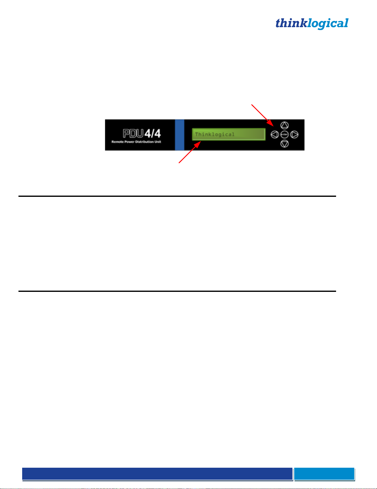
Front Panel LCD and Buttons
LCD Navigation Buttons
System Information and
Programming
The front-panel LCD should be visible and accessible for system setup. The navigation buttons are used
to configure the unit and to review existing PDU 4/4 configurations.
Use the Up and Down Arrow Buttons to scroll through the Main Menus (Port Power, System). Once the
main menu choice is shown on the display, press the Enter Button. Use the Left and Right Arrow Buttons
to navigate through the menu options.
The PDU 4/4 LCD menu is arranged as follows:
Display Modifiable Description
*Port Power
Port 1 Yes Display status of power on Port 1
Port 2 Yes Display status of power on Port 2
Port 3 Yes Display status of power on Port 3
Port 4 Yes Display status of power on Port 4
Port 5 Yes Display status of power on Port 5
Port 6 Yes Display status of power on Port 6
Port 7 Yes Display status of power on Port 7
Port 8 Yes Display status of power on Port 8
Display Modifiable Description
*System
DAISY Position No Location in DAISY Chain
Ctrl Rev No Revision of PDU
Offset Current (Tare)* Yes Calibrate current monitor on all ports.
Debug Values Yes Factory Debug Facility
*Offset Current (Tare) is only available from the front panel. This menu option sets a zero current reference and stores it
in non-volatile memory. To use this feature all ports must be off. Once the ports are off, set the Offset Current Tare to Yes,
it will revert back to No when the calibration is complete.
Convection Cooling
The PDU 4/4 does not require special cooling or ventilation other than what is normally provided in a standard
equipment rack. If mounted in an enclosed rack, the rack should have a ventilation fan to provide adequate
airflow through the unit(s).
Connecting the PDU 4/4
All physical connections to the product use industry-standard connectors. All connections are found at
the rear of the unit.
The rear panel consists of (2) AC Power Cords, (2) Circuit Breakers, (8) AC Power Outlets, (8) Port Status
LEDs, (1) USB Firmware Upgrade Port and (2) RJ45 Console Ports.
Page 8

®
PDU 4/4 Product Manual September, 2014
Page 7
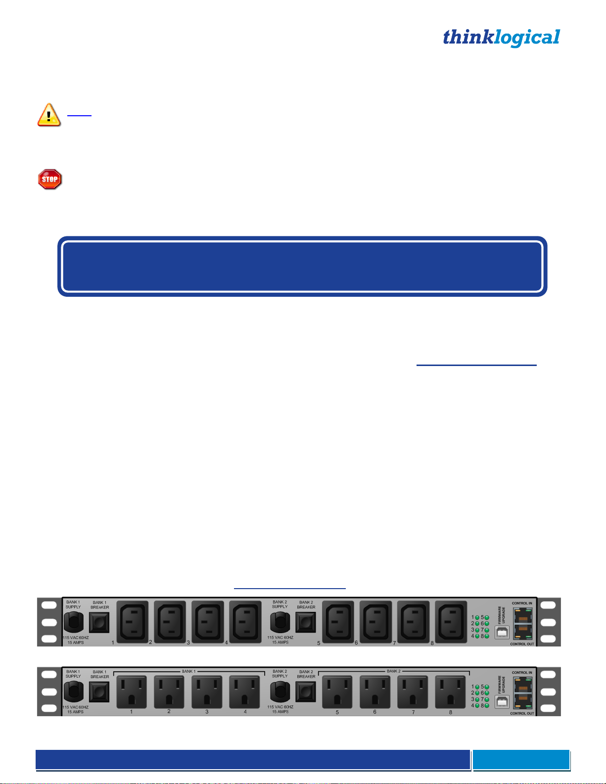
The Rear Panel
Power Connections
The rear panel features two outlet banks. Each bank consists of (1) AC Input Power Cord, (1) Power
Switch/Circuit Breaker, and (4) AC Power Outlets.
Bank 1 provides AC output power to Ports 1 through 4
Bank 2 provides AC output power to Ports 5 through 8
Domestic
Each AC Input Power Cord is outfitted with a NEMA 5-15P plug for all US/Domestic orders. Each Bank also
has a 15 Amp Power Switch/Circuit Breaker that supplies AC power to the bank of four switched outlets and
to the internal power supply. If only one Power Switch/Circuit Breaker is turned on, the internal, redundant
power supply will power the PDU and that one bank will provide AC output. If both banks are off, all outputs will
be off.
The four switched AC outlets per bank are NEMA 5-15R, nominal-115VAC power outlets. Bank 1 consists of
Ports/Outlets 1 through 4 and Bank 2 consists of Ports/Outlets 5 through 8. Each outlet is independently
controlled and can switch up to 10 Amperes. However, the total power draw for each bank of 4 outlet ports
must not exceed 15 Amperes.
Note: The total power draw for each bank of 4 outlet ports must not exceed 15 Amperes.
The two internal power supplies that are used to power the PDU system are redundant. This feature will allow
the unit to maintain power in the event of a DC Power Supply failure. Upon recovery from a power failure, the
PDU will return all Ports to the same state they were in prior to the power loss.
International
The International version of the PDU 4/4 has the same features as the Domestic version except for the
following:
Each of the (2) AC Input Power Cords are outfitted with an EU power plug.
Each of the (8) Switched AC Outlets are outfitted with a universal power outlet.
Status LEDs
The LEDs on the rear panel correspond to each of the (8) Switched AC Outlets. (For example, LED 1 shows
the status of Outlet/Port 1, LED 2 shows the status of Outlet/Port2, etc.) When the status light of an Outlet/Port
is green, the Outlet/Port has power.
USB Firmware Upgrade Port
There is a USB-B connector on the rear panel of the PDU for firmware upgrades. Firmware updates are
through a USB cable and an application that runs on a Windows (2000, XP, or Vista) PC.
Please visit http://ftp.thinklogical.com/ftp/visualization/updates for updates and instructions.
Serial Interface
The PDU 4/4 features (2) RJ45 serial connectors, labeled CONTROL IN and CONTROL OUT, on the rear
panel. If cascading multiple PDU units, the first PDU will be connected to the controlling terminal using the
CONTROL IN port. The CONTROL OUT port will be connected to the CONTROL IN port of the next unit using
a straight-through RJ45 cable, and so on.
Page 9

®
PDU 4/4 Product Manual September, 2014
Page 8
Installation
Secure
Console
Servers
SCS320 Secure Console Server
100-240V -, 0.5A, 50/60 Hz
T2A, 250 VAC
CAUTION!
Replace with same type and rating fuse.
1 2 3 4 5 6 7 8 9 10 11 12 13 14 15 16
17 18 19 20 21 22 23 24 25 26 27 28 29 30 31 32
PORTS
NETWORK
CONSOLE
www.thinklogical.com
CPU or Terminal Device
To PDU 4/4 Units 3...16
Standard AC voltage OUT
(Unit 2 Bank 1)
PDU 4/4 Unit 1
PDU 4/4 Unit 2
Unit 1 Bank 1
Devices
Unit 2 Bank 1
Devices
Unit 2 Bank 2
Devices
Unit 1 Bank 2
Devices
Individual port status LEDs
Domestic PDU 4/4 Configuration
Standard AC voltage OUT
(Unit 2 Bank 2)
Standard AC voltage OUT
(Unit 1 Bank 1)
Standard AC voltage OUT
(Unit 1 Bank 2)
The PDU is designed to stand alone or to connect to a
Thinklogical Secure Console Server®. Each device port
of the Secure Console Server is a compatible RS-232
serial port designed to connect to the PDU’s CONTROL
IN port. The PDU is installed by first connecting to the
device port using commands in the Console Server, then
once connected, by using PDU commands.
Use an Ethernet cable to connect the desired device port to the PDU's CONTROL IN port. The connection is made
with the device port configured as follows:
Refer to the Console Server Manual for Console Server
information (available online at www.thinklogical.com
Port Setting for your Terminal Device
If your switch does not have a dedicated 'Power Manager' port, you may configure a serial port to the
following settings:
Configure an RS-232 serial port as a DTE (Data Terminal Equipment) port.
Configure the port for 9600 baud, 8 data bits, No Parity, 1 Stop Bit.
Cascading the PDU Chassis
If more than eight switched AC Power ports are required, the PDU 4/4 configuration can be expanded by daisychaining up to sixteen (16) PDU 4/4 chassis. The first PDU 4/4 assumes the “Master” role, with the Master PDU 4/4’s
CONTROL OUT Port connected to the next chassis CONTROL IN Port by an RJ45 serial cable.
Box IDs
Units are only assigned master or slave status after logging in. Before log in, all boxes display a box ID of 0. The first
box assumes the Master box ID of 1. Additional PDU 4/4 boxes are designated a “Slave” status and are
Page 10

®
PDU 4/4 Product Manual September, 2014
Page 9
automatically designated with the next sequential box ID (numbered 2 through 16). All commands issued to the
master unit referencing a slave unit will be passed on to the designated box. The program parameters for each PDU
4/4 are stored in that unit. The Master unit only passes commands to the slave units.
Note: If an intermediate unit in a daisy-chain of PDU 4/4’s loses power, the control and operation of
the PDU 4/4 configuration is interrupted at the unit without power.
Program Storage
All programmed data in the PDU 4/4 is stored in non-volatile memory. In the event of a power failure, the PDU 4/4
will return each port to its previous state (on or off) when power returns to the unit.
Note: Many PC-based communications packages can buffer the entered and displayed serial data so
that it may be copied and saved to a file. Users can then keep a copy of the programmed data for
reference.
Communicating with the PDU 4/4
Programming the System
The PDU 4/4 uses a simple serial user interface. It accepts commands from a serial terminal or terminal emulation
package. The command language also provides status information upon request.
In order to enter a command function, the user must gain access to the PDU 4/4 COMMAND MODE by entering a
password to log in. Each command is completed by pressing ‘Enter’ or ‘Carriage Return’ (<CR>).
Note: In this document, ‘Enter’, ‘Return’ and <CR> represent the same action.
Programming Access
Once connected to the PDU 4/4’s CONTROL IN serial port, the following access and programming commands
may be used. Invalid commands or unauthorized access attempts will not affect the PDU 4/4. The programming
interface will automatically log out after 5 minutes of idle time.
1. Connect your programming terminal to the CONTROL IN port.
2. Press ‘Enter’ on the keyboard to establish communication. Your display should show “Password:”
If you do not get a Password prompt (or other activity), check your connections and your terminal’s configuration.
Log In
The PDU 4/4 is password protected at Log In. The factory-set password is pass (case-sensitive) which should be
changed by the System Administrator.
When Logged In, the command prompt will display PDU 4/4>
Commands
Command Principles
Serial Access
Commands are executed from the Serial terminal. You must log in order to access any programming commands.
Abbreviation
Commands may be abbreviated by typing only enough characters to differentiate 1 command from another.
Ports and Groups
Commands can be entered for individual Ports, either by name or by number; for a range of port numbers separated
by a dash (e.g., 5-8), any combination of port numbers, separated by a comma (e.g., 1,4,5,8); or for a Port Group.
A Port Group is created by assigning the same name to more than one Port. (The example group name Sun will be
used throughout this instruction.) The port name can then be used in a PDU 4/4 command.
Page 11

®
PDU 4/4 Product Manual September, 2014
Page 10
Global Commands
For configurations using multiple PDU 4/4 chassis, many commands will accept a box ID of zero (0) to
generate a Global Command that will execute the desired operation in all connected boxes.
Global commands include 0 (zero) to operate all connected PDU 4/4 box ID’s, and ALL or all for all port IDs within a
chassis or a number of cascaded chassis.
Command Replay
Commands may be “replayed” by pressing the up arrow.
HELP Command
A HELP command provides a summary of the commands and syntax for the PDU 4/4. Type “help” and press
Enter to access the HELP file at any time after logging in.
Command Help
To check the syntax of a command, type help, space, and the command name.
PDU 4/4> help
exit close session
quit close session
buttons <b> <e | d> front panel button enable/disable
help display this help or help for a command
history display command history
name <b> <name> <p#> name outlets
off <b> <p> turn an outlet or group of outlets off
on <b> <p> turn an outlet or group of outlets on
passwd change password
reboot <b> <p> reboot an outlet or group of outlets
rbdelay <b> <p> <dly> port reboot off time before reset
status <b> display outlet status
version <b> display software version(s)
<b> = (box # | all) <d> = disable <dly> = delay <e> = enable
<n> = name <t> = time <p> = (port # | name | all)
help - Help Menu
Typing help from the command line will access the HELP menu, which reviews the programming parameters for the
PDU 4/4 system.
Typing help ‘command name’ will give specific information for each command.
Exit / Quit
The Exit Command logs off the user and returns a Session Ended message. You will be immediately logged off of
the system. The System will automatically timeout and log off after 5 minutes of idle time (no terminal activity).
Note: Logging In starts a Timer that will automatically log off the current user if no activity is detected
for 5 minutes. In this case, the user will see Session Timed Out.
Buttons - Front Panel Button Enable/Disable
The Front Panel Buttons can be disabled to prevent unauthorized control of the outputs of the PDU 4/4. The LED
indicators will continue to operate, solid green LED for ON and no indicator for OFF. If buttons are enabled, selecting
on/off from the front panel will turn that outlet on or off immediately.
Page 12

®
PDU 4/4 Product Manual September, 2014
Page 11
The following commands are in alphabetical order. Do not type the angle brackets < > when entering data.
PDU 4/4> help buttons
Syntax buttons <b> <e | d>
Description: Enable or disable front panel button control.
<b> = (box # | all) <d> = disable <dly> = delay <e> = enable
<n> = name <t> = time <p> = (port # | name | all)
Examples:
Enable Front Panel Button control on Box 1 buttons 1 enable
Disable Front Panel Button control on all PDU 4/4s buttons 0 disable
history – Display Command History
The history command will show the past 16 commands. This data is not stored in non-volatile memory.
PDU 4/4> help history
Syntax: history
Description: Display previous command history.
<b> = (box # | all) <d> = disable <dly> = delay <e> = enable
<n> = name <t> = time <p> = (port # | name | all)
name - Define Port Names
The name command allows the user to assign names to each of the ports. Ports with identical names are grouped
together since commands can be issued to control the boxes by name or by port number.
The Port Names can be changed to any string of 1 to 16 characters (including all printable characters) not including
‘space’ or ‘comma’. Port names cannot start with a number.
PDU 4/4> help name
Syntax: name <b> <p> <n>
Description: Max.16 alphanumeric characters. The name must not start with a number.
<b> = (box # | all) <d> = disable <dly> = delay <e> = enable
<n> = name <t> = time <p> = (port # | name | all)
Ports and Boxes may be referred to by all, name (implying a group) or number.
Ranges of ports may be specified as 1-4 = 1,2,3,4. All may also be used.
The Define Port Names command allows the user to give each port an alias and allows the grouping of outlets. The
Port Number is not changed or affected by renaming the port, and may always be used to control the port.
Examples:
name 1 Sun 1,3,5 assigns the alias of Sun to Box 1, Ports 1, 3, and 5
name 0 Sun 1-4 assigns the alias of Sun to all Boxes, ports 1 through 4
name 0 Sun ALL assigns the alias of Sun to all Boxes, all ports
Default names are ‘DEVICE1’ through ‘DEVICE8’ for Ports 1-8, respectively.
Port Names must be between one and sixteen characters, and can include any printable characters except for ‘space’
or ’comma’. Port names cannot start with a number.
Port Groups
Port Groups can be created and controlled by assigning identical names to two or more ports. All ports with identical
names within one PDU 4/4 are grouped together provided the user enters an operational command for that name.
All ports with identical names in ALL daisy-chained PDU 4/4 chassis will be controlled provided the user enters a
valid GLOBAL (box ID = 0) command.
Page 13

®
PDU 4/4 Product Manual September, 2014
Page 12
off – Turn a Port Off
The off command is used to turn off a port or group of ports.
PDU 4/4> help off
Syntax: off <b> <p>
Description: Turn an outlet or group of outlets off.
<b> = (box # | all) <d> = disable <dly> = delay <e> = enable
<n> = name <t> = time <p> = (port # | name | all)
Ports and Boxes may be referred to by all, name (implying a group) or number.
Ranges of ports may be specified as 1-4 = 1,2,3,4. All may also be used.
Any port may be referred to by either Port Numbers or Port Names. All ports with identical port names will be turned off
together (as a Port Group)
The keyword “all” is a valid argument
Examples:
Set Box 1, Ports 5 & 7 OFF off 1 5,7
Set all boxes, ports 1 through 5, OFF off 0 1-5
If Ports 1, 4 and 8 are named SUN in Box #2, then: off 2 SUN
set ports 1, 4 & 8 OFF in Box #2.
on – Turn a Port On
The on command is used to turn on a port or group of ports. If multiple ports are turned on in one command, the turn
on times are staggered by an “rbdelay” (reboot delay) value to each port.
PDU 4/4> help on
Syntax: on <b> <p>
Description: Turn an outlet or group of outlets on.
<b> = (box # | all) <d> = disable <dly> = delay <e> = enable
<n> = name <t> = time <p> = (port # | name | all)
Ports and Boxes may be referred to by all, name (implying a group) or number.
Ranges of ports may be specified as 1-4 = 1,2,3,4. All may also be used.
Any port may be referred to by either Port Numbers or Port Names. All ports with identical port names will be turned on
together (as a Port Group)
The keyword “all” is a valid argument
Examples:
Set Box 1, Ports 5 & 7 ON on 1 5,7
Set all boxes, ports 1 through 5, ON on 0 1-5
If Ports 1, 4 and 8 are named SUN in Box #2, then: on 2 SUN
sets ports 1, 4 & 8 ON in Box #2.
Note: In order to limit current surges, each port is turned on at “rbdelay” intervals. The first port in a
sequence will turn on immediately and the next will wait until its “rbdelay” has expired before turning
on, etc.
passwd - Change Password
The factory password of “pass” can be changed to any string of 1 to 16 characters (including all printable
characters), not including ‘space’ or ‘comma’, and the new password must not start with a number.
Page 14

®
PDU 4/4 Product Manual September, 2014
Page 13
PDU 4/4> help passwd
Syntax: passwd
Description: Change the log in password.
<b> = (box # | all) <d> = disable <dly> = delay <e> = enable
<n> = name <t> = time <p> = (port # | name | all)
PDU 4/4> passwd
Password: ***
Re-enter password: ***
reboot - Reboot Output
The Reboot Output command is used to turn a port, or ports, off, and then back on. The purpose is to ‘reboot’ a
server or device by cycling the power. Ports that are currently off will be turned on. Ports that are currently on will be
turned off, then back on. The reboot time duration for each port is assigned in the rbdelay time option.
Any Port may be referred to by either Port Numbers or Port Names. All ports with identical port names will be rebooted
together (i.e., a Port Group)
The keyword “all” is a valid argument
PDU 4/4> help reboot
Syntax: reboot <b> <p>
Description: Reboot an outlet or group of outlets.
<b> = (box # | all) <d> = disable <dly> = delay <e> = enable
<n> = name <t> = time <p> = (port # | name | all)
Ports and Boxes may be referred to by all, name (implying a group) or number.
Ranges of ports may be specified as 1-4 = 1,2,3,4. All may also be used.
Examples:
Reboot Box 1, Port 8 reboot 1 8
Reboot Box 1, Ports 1, 5, and 7 reboot 1 1,5,7
Cycle all outputs OFF/ON in Box #1 reboot 1 all
If Ports 1,2,3 in Box 2 are defined as SUN2, then reboot 2 SUN2
to Reboot ports 1,2,3 in box 2
Reboot all outputs in all boxes. reboot 0 all
Note: If any of the selected ports are already ON, they will be power cycled OFF, then after a delay,
back ON. Or if any of the selected ports are OFF, they will be power cycled ON.
rbdelay - Set Reboot Time
The reboot delay command sets the time duration that a Port will remain off before turning back on after issuing a
Reboot Command to the PDU 4/4. The Time duration is adjustable from 1 to 29 seconds. Each Port may be
individually programmed.
PDU 4/4> help rbdelay
Syntax: rbdelay <b> <p> <time>
Description: Time (1 to 29 seconds) an outlet remains off before turning back on.
<b> = (box # | all) <d> = disable <dly> = delay <e> = enable
<n> = name <t> = time <p> = (port # | name | all)
Ports and Boxes may be referred to by all, name (implying a group) or number.
Ranges of ports may be specified as 1-4 = 1,2,3,4. All may also be used.
Page 15

®
PDU 4/4 Product Manual September, 2014
Page 14
status - Display Port Status
Using the status command, the user can get a snapshot report of the status of each port.
PDU 4/4> help status
Syntax: status <b>
Description: Display outlet status for all connected PDU8(s)
<b> = (box # | all) <d> = disable <dly> = delay <e> = enable
<n> = name <t> = time <p> = (port # | name | all)
PDU 4/4> status 1
Box Number 1
Button function is Enabled
Temperature is 26 degrees C
Output Name Status Delay Current (mA)
1 Port1 OFF 12 0mA
2 Port2 OFF 12 0mA
3 Port3 OFF 12 0mA
4 Port4 OFF 12 0mA
5 Port5 OFF 12 0mA
6 Port6 OFF 12 0mA
7 Port7 OFF 12 0mA
8 Port8 OFF 12 0mA
Bank 1 Current Approx. mA (15A Max.)=0
Bank 2 Current Approx. mA (15A Max.)=0
OK
Page 16

®
PDU 4/4 Product Manual September, 2014
Page 15
PDU 4/4 Technical Specifications
PDU 4/4 AC Power Distribution Unit
Storage Temperature
-20 to 70°C (-4 to 158°F), 10 to 90% RH, non-condensing
Power Supply Voltage
100 to 240 VAC, 50/60 Hz
Power Consumption
10 Watts, typical
Heat Dissipation
34 BTUs per hour
Panel Connectors
(2) AC Power Cords
(2) Power Switch/Circuit Breakers
(8) AC Power Outlets
(8) Port Status LEDs
(1) USB-B - Firmware Upgrade Port
(2) Dual RJ45 – Control In/Out Serial Ports
Front Panel Display
2 x 24 Liquid Crystal Display
Operating Temperature & Humidity
0 to 50 °C (32 to 122 °F); 5 to 95% RH, non-condensing
Enclosure Dimensions
Approx. 12.25in x 17.50in x 1.75in high
(31.1cm x 44.5cm x 4.4cm high)
Weight
Shipping Weight
11 lb (4.99 kg)
18 lb (8.16 kg)
Compliance
Approvals for US, Canada and European Union
Warranty
12 months from date of shipment. Extensions available.
PDU Models available from Thinklogical:
PDU-000001 PDU 4/4, AC Power Distribution Unit, Domestic, Serial Interface
PDU-000003 PDU 4/4, AC Power Distribution Unit, International, Serial Interface
PDU-000002 PDU2, 4x +5VDC Power Distribution Unit (PDU2 manual is on our website)
PDU-000012 PDU-12, 12x +5VDC Power Distribution Unit (PDU-12 manual is on our website)
2. Regulatory & Safety Requirements
Symbols Found on Our Products
Markings and labels on our products follow industry-standard conventions. Regulatory markings found on our
products comply with domestic and most international requirements.
Regulatory Compliance
Thinklogical® products are designed and made in the U.S.A. Products have been tested by a nationally
recognized testing laboratory and found to be compliant with the following standards (both domestic USA and
many international locations).
Page 17

®
PDU 4/4 Product Manual September, 2014
Page 16
North America
These products comply with the following standards:
Safety
ANSI/UL60950-1: 1st Edition (2003)
CAN/CSA C22.2 No. 60950-1-03
LASER Safety
CDRH 21CFR 1040.10
Class 1 LASER Product
Electromagnetic Interference
FCC CFR47, Part 15, Class A
Industry Canada ICES-003 Issue 2, Revision 1
Australia & New Zealand
This is a Class A product. In a domestic environment this product may cause radio interference, in which case
the user may be required to take adequate measures.
European Union
Declaration of Conformity
Manufacturer’s Name & Address: Thinklogical, LLC®
100 Washington Street
Milford, Connecticut 06460 USA
Telephone: 1-203-647-8700
Product Name
PDU 4/4. Models: PDU-000001 (domestic), PDU-000003 (international)
These products comply with the requirements of the Low Voltage Directive 72/23/EEC and the EMC Directive
89/336/EEC.
Standards with Which Our Products Comply
Safety
CENELEC EN 60950-1, (2006)
LASER Safety
IEC60825:2001 Parts 1 and 2
Class 1 LASER Product
Electromagnetic Emissions
EN55022: 1994 (IEC/CSPIR22: 1993)
EN61000-3-2/A14: 2000
EN61000-3-3: 1994
Electromagnetic Immunity
EN55024: 1998 Information Technology Equipment-Immunity Characteristics
EN61000-4-2: 1995 Electro-Static Discharge Test
EN61000-4-3: 1996 Radiated Immunity Field Test
EN61000-4-4: 1995 Electrical Fast Transient Test
EN61000-4-5: 1995 Power Supply Surge Test
EN61000-4-6: 1996 Conducted Immunity Test
EN61000-4-8: 1993 Magnetic Field Test
EN61000-4-11: 1994 Voltage Dips & Interrupts Test
Page 18

®
PDU 4/4 Product Manual September, 2014
Page 17
Supplementary Information
The following statements may be appropriate for certain geographical regions and might not apply to your
location.
This Class A digital apparatus meets all requirements of the Canadian Interference-Causing
Equipment Regulations.
Cet appareil numérique de la classe A respecte toutes les exigencies du Règlement sur le matérial
brouilleur du Canada.
Warning! This is a Class A product. In a domestic environment, this product may cause radio
interference, in which case the user may be required to take adequate corrective measures.
Note: This equipment has been tested and found to comply with the limits for a Class A digital
device, pursuant to part 15 of the FCC Rules. These limits are designed to provide reasonable
protection against harmful interference when the equipment is operated in a commercial
environment. This equipment generates, uses and can radiate radio frequency energy and, if
not installed and used in accordance with the instruction manual, may cause harmful
interference to radio communications in which case the user may be required to take adequate
corrective measures at their own expense.
Note: This Class A digital apparatus complies with Canadian ICES-003 and has been verified as
being compliant within the Class A limits of the FCC Radio Frequency Device Rules (FCC Title
47, Part 15, Subpart B CLASS 1), measured to CISPR 22: 1993 limits and methods of
measurement of Radio Disturbance Characteristics of Information Technology Equipment.
Note:
fields
Note:
be needed to comply with Immunity Requirements
The user may notice degraded audio performance in the presence of electromagnetic
.
If using a keyboard that is noise susceptible, a ferrite ring on the keyboard cable may
Product Serial Number
Thinklogical products have a unique serial number, which includes a date-code, printed on an adhesive label
that is affixed to the unit. The format for the date-code is 2 digits for the month, dash, 2 digits for the year, plus
four digits for a unique unit number. For example, 05-140125 indicates the unit was built in the 5th month of
2014, and is unit number 125. Connection to the Product
Connection to the Product
Connections and installation hardware for our products use industry-standard devices and methods. All wiring
connections to the customer equipment are designed to minimize proprietary or customized connectors and
cabling. Power connections are made with regionally appropriate power cords and approved methods.
Page 19

®
PDU 4/4 Product Manual September, 2014
Page 18
3. Thinklogical Support
Thank you for choosing Thinklogical® products for your application.
We appreciate your business and are dedicated to helping you successfully use our products.
is always here to help you.
To contact us, please use the following telephone numbers and internet-based methods:
®
Customer Support
Thinklogical is an engineering company and you will receive any information you require directly from
our most knowledgeable engineers. We believe that the first lines of support are design engineers that
developed each particular product. Therefore, your questions will be handled promptly by our in-house
engineers who are most familiar with your products.
Website
Check out our website for current product offerings, support information and general information about all of
the products we offer, including product information on all current systems, technical specification sheets, quick
start guides (for viewing online or for download), product diagrams showing physical connections and other
helpful information.
Internet: www.thinklogical.com
Note: Most online documents are stored as Adobe Acrobat “PDF” files. If you do not have the
Adobe Acrobat reader needed to view PDF files, visit www.adobe.com for a download.
Email
Thinklogical is staffed Monday through Friday from 8:30am to 5:00pm, Eastern Time Zone. We will do our
best to respond to your email inquiries promptly. Please use one of the following email addresses:
info@thinklogical.com – Information on Thinklogical® and our products.
sales@thinklogical.com – Sales Department - orders, questions or issues.
support@thinklogical.com – Product support, technical issues or questions, product
repairs and request for Return Authorization.
Telephone
Product & Customer Support: 1-203-647-8700
US Commercial & Canada Sales: 1-203-647-8769
US Federal Government Sales: 1-203-647-8716
Toll Free in the Continental US: 1-800-291-3211
International Sales (Europe, Middle East, Africa): 1-203-647-8704
International Sales (Asia Pacific, Central & Latin America): 1-203-647-8734
Fax: 1-203-783-9949
Please contact our expert sales staff in Milford, CT. We are here Monday through Friday from 8:30am to
5:00pm, Eastern Time Zone. We’ll provide a representative’s direct dial phone number when you call.
Page 20

®
PDU 4/4 Product Manual September, 2014
Page 19
If leaving a voice message, please provide a preferred time to call back so we may reach you at your
convenience.
Our switchboard attendant will direct your call during regular business hours. We have an automated attendant
answering our main telephone switchboard after regular business hours and holidays. You can leave voice
messages for individuals at any time.
Fax
Our company facsimile number is 1-203-783-9949. Please indicate the nature of the fax on your cover sheet
and provide return contact information.
Product Support
Thinklogical’s support personnel are available Monday through Friday from 8:30am to 5:00pm, Eastern Time
Zone. If your application might require assistance at some time outside of our normal business hours, please
contact us beforehand and we will do our best to make arrangements to help you with your Thinklogical
products.
Warranty
Thinklogical® warrants this product against defects in materials and workmanship for a period of one year from
the date of delivery. Thinklogical and its suppliers disclaim any and all other warranties.
Note: Thinklogical products carry a one year warranty, with longer term available at time of
purchase on most products. Please refer to your product invoice for your products Warranty
Terms & Conditions.
Defect remedy shall be, repair or replacement of the product, provided that the defective product is returned to
the authorized dealer within a year from the date of delivery.
If you wish to return your device, contact the Thinklogical-authorized dealer where you purchased the device,
or if you purchased directly, call Thinklogical at 1-800-291-3211 (USA).
Return Authorization
If you have any issue with any Thinklogical product, have product questions or need technical assistance with
your Thinklogical system, please contact Customer Support at 1-800-291-3211 (USA only) or 1-203-647-
8700 and let us help.
If you must return a product to Thinklogical® directly, Customer Support will ask you to describe the problem
and will issue you a Return Merchandise Authorization number (RMA#).
Pack the device in its original box, if possible, and return it with the RMA# on the box.
Note: Do not return a product to Thinklogical® without a Return Material Authorization Number.
Return address for products with Return Material Authorization:
Thinklogical, LLC®
Attn: RMA#
100 Washington Street
Milford, CT 06460 USA
PH: 800-291-3211 (USA only)
Page 21

®
PDU 4/4 Product Manual September, 2014
Page 20
Appendix A: PDU 4/4 Quick Start Guide
QUICK START
GUIDE
QUICK START
GUIDE
PDU 4/4
CPU or Terminal Device
To PDU 4/4 Units 3...16
Standard AC voltage OUT
(Unit 2 Bank 1)
PDU 4/4 Unit 1
PDU 4/4 Unit 2
Unit 1 Bank 1
Devices
Unit 2 Bank 1
Devices
Unit 2 Bank 2
Devices
Unit 1 Bank 2
Devices
Individual port status LEDs
Each PDU4/4 system includes the following
features:
Eight individually-controlled AC power outlets
(available for both domestic and international)
Dual 15 Amp (max) circuits, four outlets per
circuit
Redundant DC power supplies for built-in I/O
and control circuits
Individually programmable Reboot Time
Delay on each outlet
Solid state zero-crossing relays to minimize
power spikes
Easily expandable configuration
Password Security User-definable Port Names and Port Groups
Front panel display for easy system set up
and configuration
Current monitoring of each port.
The PDU 4/4 is designed for desktop or 19"
rack mounting (1U).
Software updates available at
ftp.thinklogical.com
PDU_4-4_Domectic_manual_QSG
Domestic PDU 4/4 Configuration
Standard AC voltage OUT
(Unit 2 Bank 2)
Standard AC voltage OUT
(Unit 1 Bank 1)
Standard AC voltage OUT
(Unit 1 Bank 2)
Thinklogical’s® PDU 4/4 Power Distribution Unit is an AC Power Switch that remotely controls power to up to eight devices per unit.
The PDU 4/4 communicates with its control terminal using a serial interface and provides control to all devices with simple commands to turn power off or
on to reboot any one port, multiple ports, port groups or all devices.
Power restarts can be sequenced using programmed time delays to minimize surge or allow drive spin-up time.
Your configuration can be easily expanded with one serial cable for each PDU 4/4 unit added .
A single serial interface integrates the control of all PDU 4/4s in your application.
Up to sixteen PDU 4/4s can be cascaded together to control multiple systems from one common user interface.
Each outlet individually switches up to 10 Amperes maximum with each bank rated at 15 Amperes total.
Each PDU 4/4 utilizes two banks of four outlets and rear panel LEDs display the status of each port.
The on command is used to turn on a port or group of ports. Any port may be referred to by either Port Numbers or Port Names. All ports with identical port names will be turned on together (as a Port Group).
The off command is used to turn off a port or group of ports.
The reboot output command is used to ‘reboot’ a server or device by cycling power to a port or ports. Refer to the user’s manual for further commands.
Once connected to the PDU 4/4’s CONTROL IN serial port, the following access and programming commands may be used:
Press ‘Enter’ on the keyboard to establish communication. Your display will show “Password:” The factory-set password is pass and may be changed by the System
Administrator. When Logged In, the command prompt will show “PDU 4/4>”. Commands are executed from the Serial Terminal.
 Loading...