

Page 1
Page 2

®
Q - S e r i e s V i d e o M o d u l e s P r o d u c t M a n u a l , R e v . I
Page 2
Q-Series Chassis
& Modules
®
2014
2013
Copyright Notice
Copyright © 2015. All rights reserved. Printed in the U.S.A.
Thinklogical, LLC®
100 Washington Street
Milford, Connecticut 06460 U.S.A.
Telephone: 1-203-647-8700
All trademarks and service marks are property of their respective owners.
Subject: Velocity Q-Series Video Modules Product Manual
Release: Rev. I, February, 2015
Website: www.thinklogical.com
Facebook: www.facebook.com/ThinklogicalUSA
LinkedIn: www.linkedin.com/company/thinklogical
Google+: http://plus.google.com/u/0/109273605590791763795/about
YouTube: www.youtube.com/user/thinklogicalNA
Twitter: @thinklogical
Page 3

®
Q - S e r i e s V i d e o M o d u l e s P r o d u c t M a n u a l , R e v . I
Page 3
Table of Contents
PREFACE 4
About Thinklogical 4
Note and Warning Symbols 5
1. INTRODUCTION 6
1.1 Product Overview 6
2. SYSTEM FEATURES 7
2.1 General System Features 7
2.2 The Q-Series Chassis Line 7
3. THE Q-SERIES VIDEO SYSTEM 8
3.1. Types of Connectors 8
3.1.1. Fiber Optic Cable 8
3.1.2. Transmitter 8
3.1.3. Receiver 8
4. THE Q-SERIES VIDEO MODULES 12
4.1. Single-Link and Dual-Link DVI & RGB/DVI Modules 12
4.2. Velocity Q-Series HDCP Compliant Video Modules 17
4.2.1. Velocity Q-Series HDCP Compliant Video Module Part Numbers 18
4.2.2. Velocity Q-Series HDCP Compliant Video Module Front Panel Views 18
4.3. Fiber Connections to the Q-Series Video Modules 19
4.3.1. Single Fiber Operation, Single-Link Video 19
4.3.2. Dual Fiber Operation, Single-Link Video 19
4.3.3. Three and Four Fiber Operation, Dual Video 20
4.3.4. Two and Four Fiber Operation, Redundant Video 20
4.3.5. Two and Three Fiber Operation, Dual-Link Video 20
4.4. Supplied Cables 20
4.5. Dry Contact Alarm 22
4.6. Q-Series Video Module Audio Specifications 23
4.7. Q-Series Video Modules Technical Specifications 23
4.8. Status Indicator LEDs 24
4.8.1. Scaler Receiver Status LEDs 24
4.8.2. Q-Series Video Modules Tx and Rx Status LEDs 25
4.9. Firmware and FPGA Updates 26
5. REGULATORY & SAFETY COMPLIANCE 27
5.1 Safety Requirements 27
Symbols Found on the Product 27
Regulatory Compliance 27
North America 27
Australia & New Zealand 27
European Union 27
Standards with which Our Products Comply 27
5.2 Supplementary Information 28
Product Serial Number 28
Connection to the Product 28
6. HOW TO CONTACT US 28
6.1 Customer Support 28
Website, Email, Telephone, Fax 29
6.2 Product Support 30
6.2.1 Warranty 30
6.2.2 Return Authorization 30
Our Addresses 30
APPENDIX A: Quick Start Guides 31
APPENDIX B: VQM-10 AV+ Supported Analog Resolutions 35
APPENDIX C: VQM-10 AV+ LCD Menu Options (Q-2300 & Q-4300 Chassis) 36
APPENDIX D: VQM-3 Scaler Menu Options 44
APPENDIX E: RJ45 to DB9 Adapter Pin-outs 51
APPENDIX F: EDID and DDC for Standard and HDCP Modules 52
Page 4

®
Q - S e r i e s V i d e o M o d u l e s P r o d u c t M a n u a l , R e v . I
Page 4
PREFACE
Thinklogical, LLC®
100 Washington St.
Milford, CT 06460
2014
2013
We, the Thinklogical team, are committed to understanding and
exceeding our customers’ requirements, the first time and every time.
About Thinklogical
Thinklogical is the leading manufacturer and provider of fiber optic KVM, video, audio, and
peripheral extension and switching solutions used in video-rich, big-data computing
environments.
Thinklogical offers the only fiber-optic KVM matrix switches in the world that
are accredited to the Common Criteria EAL4, TEMPEST Level B, and NATO
NIAPC Evaluation Scheme: GREEN information assurance standards.
Governments, entertainment, scientific and industrial customers worldwide rely on
Thinklogical’s products and solutions for security, high performance, continuous operation
and ease of integration. Thinklogical products are designed and manufactured in the USA
and are certified to the ISO 9001-2008 standard.
Thinklogical is headquartered in Milford, Connecticut and is privately held by Riverside
Partners, LLC, Boston, MA (http://www.riversidepartners.com). For more information about
Thinklogical products and services, please visit www.thinklogical.com.
Follow Thinklogical on LinkedIn at http://www.linkedin.com/company/thinklogical and on
Facebook at http://www.facebook.com/ThinklogicalUSA
Page 5
®
Q - S e r i e s V i d e o M o d u l e s P r o d u c t M a n u a l , R e v . I
Page 5
BEFORE STARTING ANY PROCEDURE, IT IS RECOMMENDED
THAT YOU READ THE INSTRUCTIONS THOROUGHLY!
CLASS 1 LASERS do not require any special
precautions under conditions of normal use.
SFP
Modules
Fiber-Optic
Cables
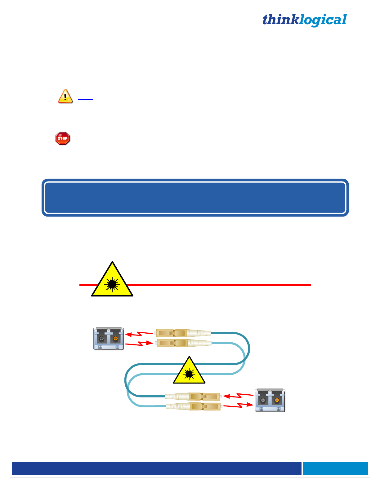
Class 1 Lasers
Note and Warning Symbols
Throughout this manual you will notice certain symbols that bring your attention to important information.
These are Notes and Warnings. Examples are shown below.
Note: Important Notes appear in blue text preceded by a yellow exclamation point
symbol, as shown here.
A note is meant to call the reader’s attention to helpful information at a point in the text that is relevant to
the subject being discussed.
Warning! All Warnings appear in red text, followed by blue text, and preceded by a
A warning is meant to call the reader’s attention to critical information at a point in the text that is relevant
to the subject being discussed.
red stop sign, as shown here.
All Q-Series modules are designed and identified as Class 1 LASER products
.
Page 6
®
Q - S e r i e s V i d e o M o d u l e s P r o d u c t M a n u a l , R e v . I
Page 6
1. Introduction
MADE IN USA
VQM DVI Transmitter with Audio
H: 1.592” (4.40cm) x D: 6.366” (45.8cm) x W: 7.406” (44.5cm), 10 Watts per unit
1.1. Product Overview
MRTS Technology 6.25 Gbps. allows for Full Frame Rate Transmission of uncompressed DVI or
RGB video. Powered by Thinklogical’s® cutting edge, patent-pending MRTS (Multi Rate Transmission
System) Technology, our video extension systems transport every frame of a DVI or RGB video stream
seamlessly with no compression or dropped frames. In addition, all high speed peripherals function with
no latency. Incorporating standard SFP+ transceivers, the system uses fiber optic cables to
placement of a digital monitor or projector up to 1000 meters (3280 feet) away from the controlling
computer without loss of resolution. Installation is plug-and-play and no adjustments are necessary.
All Video modules support Data Display Channel (DDC)*, with a variety of modes to meet each
unique requirement. All models are connected by fiber optic cable(s), to provide communications to
and from the transmitter. The transmitter modules connect to a CPU with supplied video cables
(and audio & serial or network cables in AV+, AN+, AH and NH models). The receiver modules
provide an interface to the monitor(s) (and audio & serial or network devices in AV+, AN+, AH, NH
and video format scaler models).
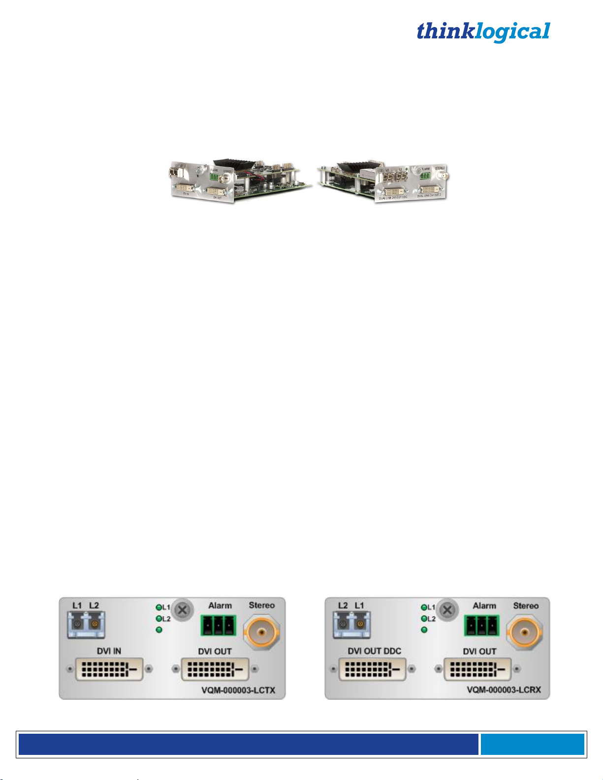
Each
video output which can be used for DDC modification and for displaying video at the source. The TX
also has fiber connectors used for transferring video and data to the Receiver. Status LEDS are
provided for system information.
Each
output labeled DDC is always the primary output. The RX also has fiber connectors used for
transferring data to the TX and receiving video and data.
VQM Video Transmitter
VQM Video Receiver
(RX)
(TX)
Module
Module
features a video input and, in many cases, a local
features 2 video outputs. On single DVI models, the video
permit the
*See page 52: Appendix F: EDID and DDC for Standard and HDCP Modules
Page 7
®
Q - S e r i e s V i d e o M o d u l e s P r o d u c t M a n u a l , R e v . I
Page 7
2. System Features
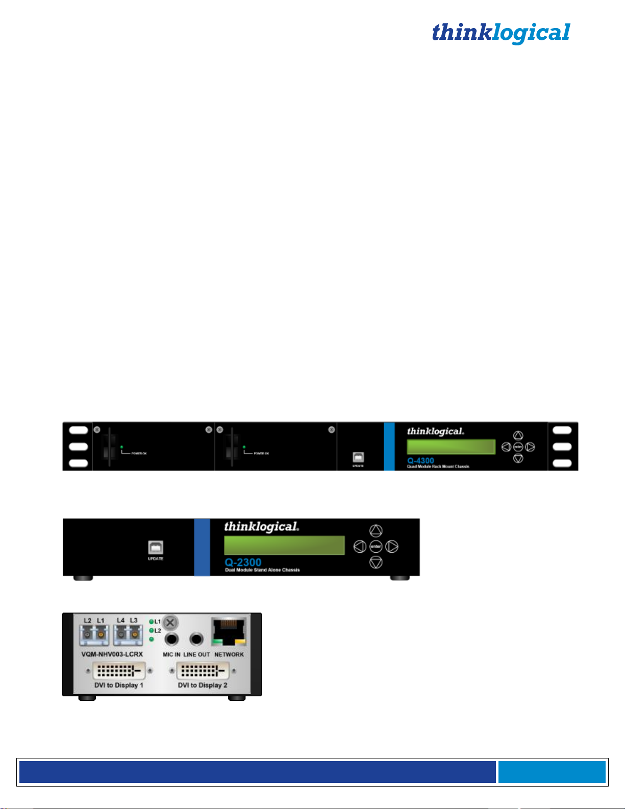
Q-4300 Chassis: (VQS-004300) Supports any combination of up to four Q-Series modules.
Dual interface and current sharing power supplies. Desktop or 19" rack-mount.
Q-2300 Chassis: (VQS-002300) Supports up to two Q-Series modules. Desktop only.
Q-1300 Chassis: (VQS-001300) Supports one Q-Series module. Desktop only.
2.1 General System Features
The Q-Series’ hot-swappable interface modules allow any Q-Series Chassis to be used in a variety of
applications. Both transmitter and receiver modules can be installed together in one chassis. (A Q-4300
Chassis can hold up to four modules and a Q-2300 Chassis can hold up to two modules). Video Modules
are available to support single-link or dual-Link video display connections along with full duplex stereo
audio, stereo 3D emitter and serial RS-232 or network. A line of HDCP Compliant Velocity Q-Series
modules is also available (see pg. 17).
Installation possibilities are expanded with built-in support for either multi-mode or single mode fiber,
making this a convenient and cost effective solution to combat the restrictions involved with the
distribution of uncompressed broadcast quality video signals over long distances. Each module is hot
swappable and, in addition, the standard SFP+ optics (with LC connectors) are hot swappable/hot
pluggable. Every module is fully compatible with all of Thinklogical’s VXRouter line of products.
2.2 The Q-Series Chassis Line
Each Q-Series chassis allows users to locate DVI, RGB/DVI and SDI monitors (via fiber) from just a few
meters away to up to 40 kilometers away from the controlling computer, securely and without the loss of
resolution.
The Q-4300 is a rack space-saving, high reliability solution that provides a rack mount for up to 4
modules of DVI, RGB or SDI in a compact 1U chassis. Ready for the challenges of demanding
applications, both the Q-4300 and Q-2300 Chassis can combine any variety of DVI, RGB/DVI or SDI
modules in transmit/receive units for a space saving and cost effective solution.
The Q-1300 is a stand-alone chassis that will accommodate any one Q-Series module. All Q-Series
Chassis are powered by standard 100-240 VAC, 47-63 Hz.
Page 8
®
Q - S e r i e s V i d e o M o d u l e s P r o d u c t M a n u a l , R e v . I
Page 8
3. The Q-Series Video System
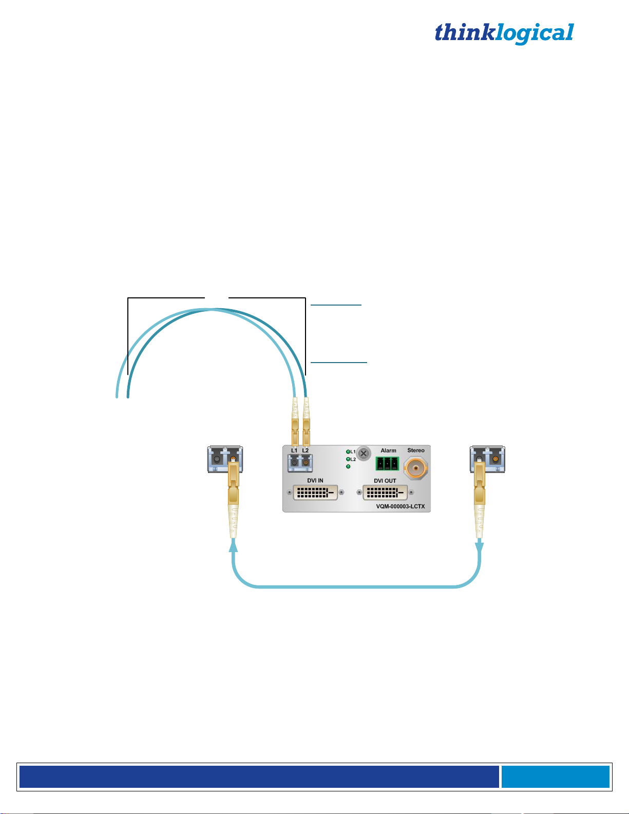
Multi-Mode Fiber-Optic Cable
T R T R
LC
TransmitReceive
LC
3"
Multi-Mode:
Up to 50 meters with Type OM1
Up to 350 meters with Type OM2
Up to 750 meters with Type OM3
Up to 1000 meters with Type OM4
Single Mode:
Up to 80km with Type OS2 9/125 for all distances
3.1. Types of Connections
All physical connections to the product use industry-standard connectors. Non-supplied cables
that may be needed are commercially available. All connections are found on the front panels of the
modules.
All models are connected via fiber optic cables (see paragraph 4.3. on page 19) to provide
communications to and from the transmitter. The transmitter connects to the CPU with supplied
Video
provides an interface to the monitor(s) and audio, serial or network devices in AV+, AN+, AH, NH
and video format scaler models. RJ45 to DB9 serial adapters are included with each transmitter and
receiver.
3.1.1 Fiber Optic Cable
cables (and audio & serial or network cables in AV+, AN+, AH and NH models). The receiver
Fiber optic cables
up to 1000 meters (3280 feet)
connect the Transmitters to the Receivers. Standard
multi-mode fiber optic cables must be 50 or 62.5 microns, terminated with LC type fiber optic connectors.
Be careful not to kink or pinch the fiber optic cable as it is being installed and keep all bend
diameters to no less than 3 inches (76.2mm).
3.1.2 Transmitter
A transmitter unit connects to the computer and peripheral sources through standard copper cables. The
connector configurations of the Q-Series Transmitters can be viewed in detail on pages 12-17.
A receiver module connects to a viewing device (monitor, projector) and USB and audio devices with
their own standard cables. The connector configurations of the Q-Series Module Receivers can be
viewed in detail on pages 12-17.
3.1.3 Receiver
Page 9
®
Q - S e r i e s V i d e o M o d u l e s P r o d u c t M a n u a l , R e v . I
Page 9
DVI IN Mod
.
1
DVI IN Mod
.
2
DVI IN Mod
.
3
DVI IN Mod
.
4
STEREO
3
-
D COAX IN
(
Source
4
)
DVI OUT Mod
.
1
DVI OUT Mod
.
2
DVI OUT Mod
.
3
DVI OUT Mod
.
4
STEREO
3-
D OUT
(
Source
4
)
DVI OUT DDC
Mod
.
4
DVI OUT DDC
Mod
.
3
DVI OUT DDC
Mod
.
2
DVI OUT DDC
Mod
.
1
Local DVI OUT
Mod
.
4
Local DVI OUT
Mod
.
3
Local DVI OUT
Mod
.
2
Local DVI OUT
Mod
.
1
Q-4300 Transmitter Modules’ Local Displays
Control CPU
HDX
576
Router
Source CPUs
Q
-
4300
:
Transmitters
Q
-
4300
:
Receivers
Q-4300 Receiver Modules’ DDC OUT Displays
1
2
3
4
Q-4300:
Four VQM-3V Transmitter Modules
(VQM-00V003-LCTX)
DVI Fibers:
è L1: Video & Data Tx to Rx
ç L2: Data Rx to Tx
Source CPUs
1
&
2
,
3
V Mod
.
4
Source CPUs
1
&
2
,
3
V Mod
.
3
Source CPUs
1
&
2
,
3
V Mod
.
2
Source CPUs
1
&
2
,
3
V Mod
.
1
Q-4300:
Four VQM-3V Receiver Modules
(VQM-00V003-LCRX)
DVI OUT
Mod
.
4
-
1
DVI OUT
Mod
.
3
-
1
DVI OUT
Mod
.
2
-
1
DVI OUT
Mod
.
1
-
1
DVI OUT
Mod
.
4
-
2
DVI OUT
Mod
.
3
-
2
DVI OUT
Mod
.
2
-
2
DVI OUT
Mod
.
1
-
2
DVI IN Mod
.
1
DVI IN Mod
.
2
DVI IN Mod
.
3
DVI IN Mod
.
4
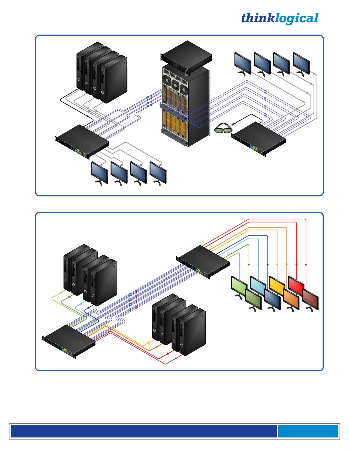
The VQM-3 Fiber Extension System- Up to 4 Single-Link DVI video signals can be extended in 1 RU
The VQM-3V Fiber Extension System- Up to 8 Independent Single-Link DVI video signals can be extended
in 1 RU
Page 10
®
Q - S e r i e s V i d e o M o d u l e s P r o d u c t M a n u a l , R e v . I
Page 10
DVI Mod
.
1
DVI Mod
.
2
DVI Mod
.
3
DVI Mod
.
4
Q-4300:
4 VQM-3R Redundant Transmitter
Modules
(VQM-00R003-LCTX)
Fiber Optic Cables:
è L1/L1': Video & Data Tx to Rx/ Video & DataTx to Rx'
ç L2/L2': Data Rx to Tx/Data Rx to Tx’
Source CPU Mod
.
4
Source CPU Mod
.
3
Source CPU Mod
.
2
Source CPU Mod
.
1
Q-4300:
4 VQM-3R Redundant Receiver
Modules
(VQM-00R003-LCRX)
DVI OUT
Mod
.
4
DVI OUT
Mod
.
3
DVI OUT
Mod
.
2
DVI OUT
Mod
.
1
DVI OUT
DDC
Mod
.
4
DVI OUT
DDC
Mod
.
3
DVI OUT
DDC
Mod
.
2
DVI OUT
DDC
Mod
.
1
Local DVI
OUT Mod
.
4
Local DVI
OUT Mod
.
3
Fiber Optic Cables
Rx
Local DVI
OUT Mod
.
1
Local DVI
OUT Mod
.
2
Tx
DVI IN Mod
.
1
DVI IN Mod
.
2
DVI IN Mod
.
3
DVI IN Mod
.
4
STEREO
3
-
D COAX IN
(
Source
4
)
DVI OUT Mod
.
1
DVI OUT Mod
.
2
DVI OUT Mod
.
3
DVI OUT Mod
.
4
STEREO
3-
D OUT
(
Source
4
)
DVI OUT DDC
Mod
.
4
DVI OUT DDC
Mod
.
3
DVI OUT DDC
Mod
.
2
DVI OUT DDC
Mod
.
1
Local DVI OUT
Mod
.
4
Local DVI OUT
Mod
.
3
Local DVI OUT
Mod
.
2
Local DVI OUT
Mod
.
1
Q-4300 Transmitter Modules’ Local Displays
Control CPU
VX
320
Router
Source CPUs
Q
-
4300
:
Transmitters
Q
-
4300
:
Receivers
Q-4300 Receiver Modules’ DDC OUT Displays
1
2
3
4
Dual-Link DVI Fibers:
è L1: Data Tx to Rx & Video Primary
ç L2: Data Rx to Tx
è L3: Video Secondary
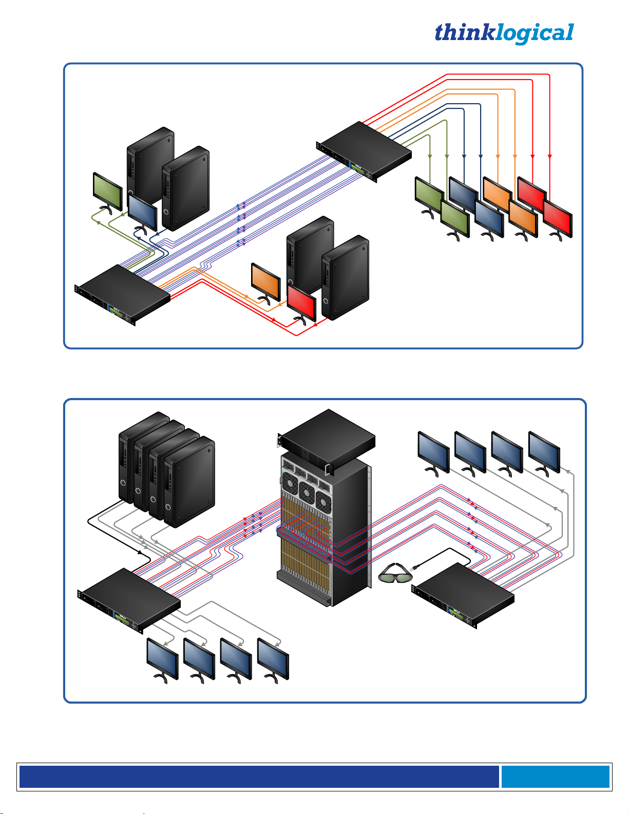
The VQM-3R Fiber Extension System- Up to 4 Single-Link DVI video signals can be extended in 1 RU with
4 Redundant Fiber Paths
The VQM-6 Fiber Extension System- Up to 4 Single-Link DVI video signals can be extended in 1 RU
Page 11
®
Q - S e r i e s V i d e o M o d u l e s P r o d u c t M a n u a l , R e v . I
Page 11
Stereo
3-
D Coax IN
Fiber
-
Optic Cables
Control CPU
VX
320
Router
Q-4300 (2)
Q-4300 (1)
Q-4300 (1) RX
Module’s Destinations
Local DVI OUT
Q
-
4300
(
2
)
TX
DVI OUT DDC
Q
-
4300
(
1
)
RX
Source CPU 1
to Q-4300 (1)
TX Module
DVI OUT DDC
Q
-
4300
(
2
)
RX
DVI OUT
Q
-
4300
(
2
)
RX
Source CPU 2
to Q-4300 (2)
TX Module
Stereo
3
-
D OUT
Q
-
4300 (
2
)
RX
Local DVI OUT
Q
-
4300
TX
(
1
)
Active
Network
Active
Network
Vel-
3AN+ RX
Module
Vel-
3AN+ TX
Module
Network
Device
Network
Device
Data
Video
Stereo 3-D Coax IN
Data
Video
DVI OUT
Q
-
4300
(
1
)
RX
Vel-
3AN+ TX
Module
Vel-
3AN+ RX
Module
Fiber
-
Optic Cables
Q-4300 (2) RX
Module’s Destinations
Stereo
3-
D OUT
Q
-
4300
(
1
)
RX
Local DVI OUT
VQM-6 A/V+
Module 1
Source to
VQM-6 A/V+
Tx Module 1
Q-4300 Tx
Destination of
VQM-6 A/V+ Tx
Module 1
Fiber Optic Cables
DDC
Velocitydvi-6 A/V+ Rx 1
Local DVI OUT
VQM-6 A/V+
Module 2
Source to
VQM-6 A/V+
Tx Module 2
Destination of
VQM-6 A/V+ Tx
Module 2
DDC
Velocitydvi-6 A/V+ Rx 2
Fiber Optic Cables
Fiber-Optic Cables:
L1: Data Tx to Rx & Video 1
L2: Data Rx to Tx
L3: Video 2
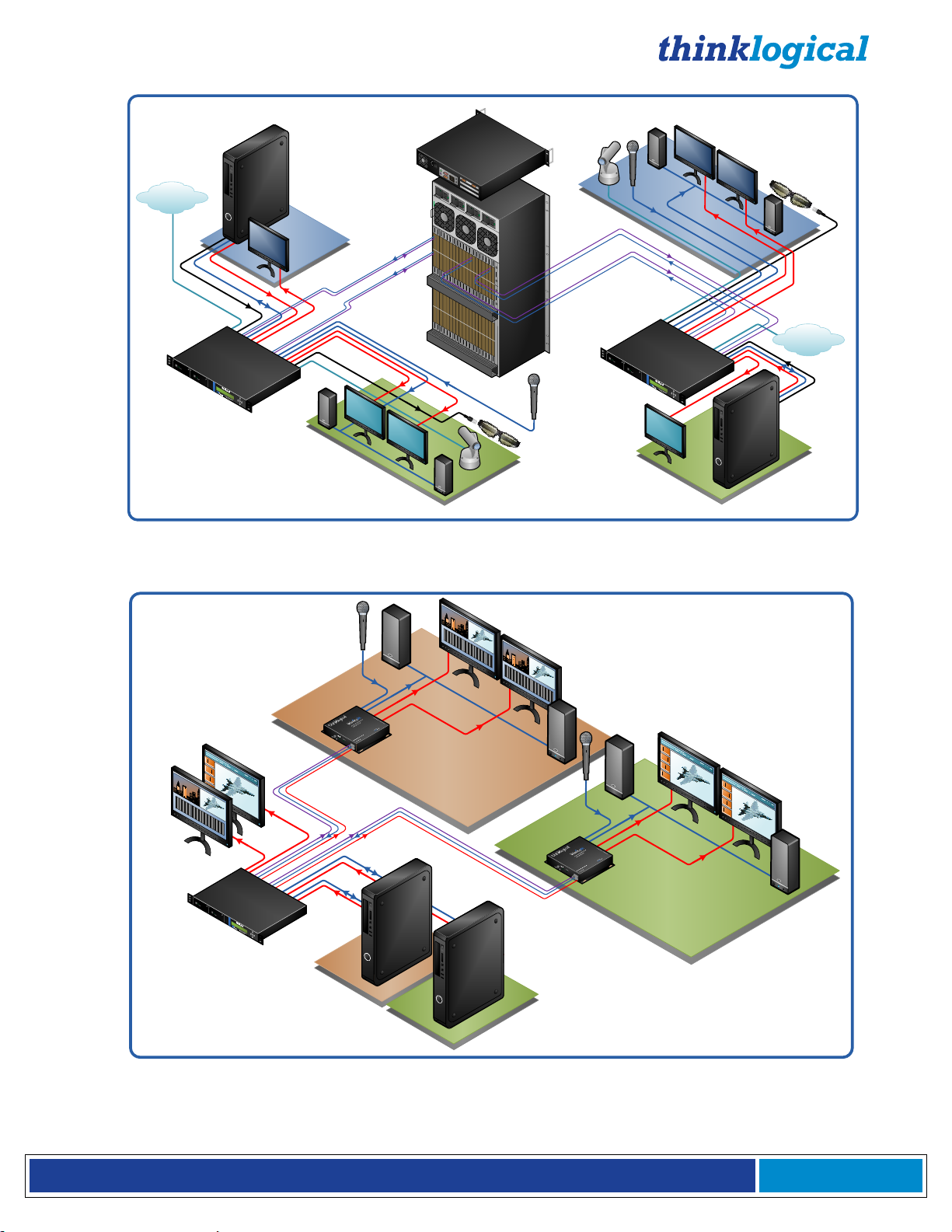
The VQM-3AN+ Fiber Extension System- Up to 2 Single-Link DVI video signals plus a network connection
can be extended in 1 RU
The VQM-6AV+ to Vel-6AV+ Fiber Extension System Configuration- Up to 2 Single-Link DVI video
signals plus audio can be extended in 1 RU
Page 12
®
Q - S e r i e s V i d e o M o d u l e s P r o d u c t M a n u a l , R e v . I
Page 12
4. The Q-Series Video Modules
This section lists the various DVI and RGB/DVI Modules designed to work with the Q- Series
Video and Audio Extension System. Supported video formats include DVI and RGB/DVI singlelink and dual-link and a line of HDCP compliant models. Models are also available with Audio
(AV+, AH), Network (AN+, NH) and video format scaler options. See page 23 for audio
specifications and page 52, Appendix F: EDID and DDC for Standard and HDCP Modules.
4.1 Single-Link and Dual-Link DVI & RGB/DVI Modules:
VQM-3, VQM-3R, VQM-3AV+, VQM-3RAV+, VQM-3AN+ & VQM-3RAN+ module features:
Supports all Single-Link DVI video resolutions
MRTS technology 6.25Gbps allows for full frame rate transmission of uncompressed DVI
Signal transmission via fiber optic cable; no RF interference
Requires one or two fiber optic cables depending on application
Flawless image quality with no frame dropping
Local video port on the transmitter
Additional video output on the receiver
Redundant Fiber Path (VQM-00R003 models only)
Audio and RS-232 serial port (on AV + models only)
Audio and Network port (on AN + models only)
DDC2B/EDID compliant
Simple plug and play
VQM-3V, VQM-3V AV+ and VQM-3V AN+ module features:
Up to 8 independent Single-Link DVI video signals can be extended in 1 RU
Supports all Single-Link DVI video resolutions
Two DVI-D signals can be extended with one module
MRTS technology 6.25Gbps allows for full frame rate transmission of uncompressed DVI
Signal transmission via fiber optic cable; no RF interference
Requires two or four fiber optic cables depending on application
Flawless image quality with no frame dropping
Audio and RS-232 serial ports (on AV + models only)
Audio and Network ports (on AN + models only)
DDC2B/EDID compliant
Simple plug and play
VQM-3, VQM-3V and VQM-3R Tx and Rx DVI Modules:
VQM-3, TX Single Video VQM-3, RX Single Video
Page 13
®
Q - S e r i e s V i d e o M o d u l e s P r o d u c t M a n u a l , R e v . I
Page 13
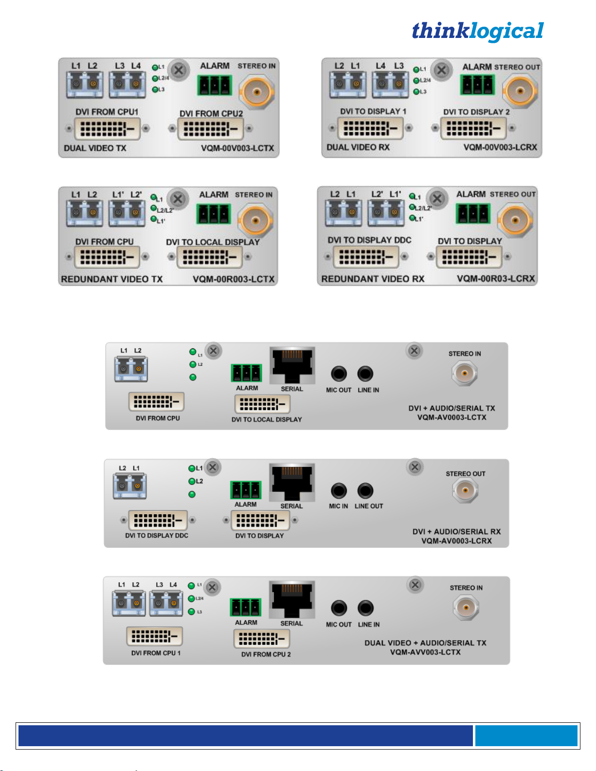
VQM-3V, TX Dual Video VQM-3V, RX Dual Video
VQM-3R, TX Redundant Video VQM-3R, RX Redundant Video
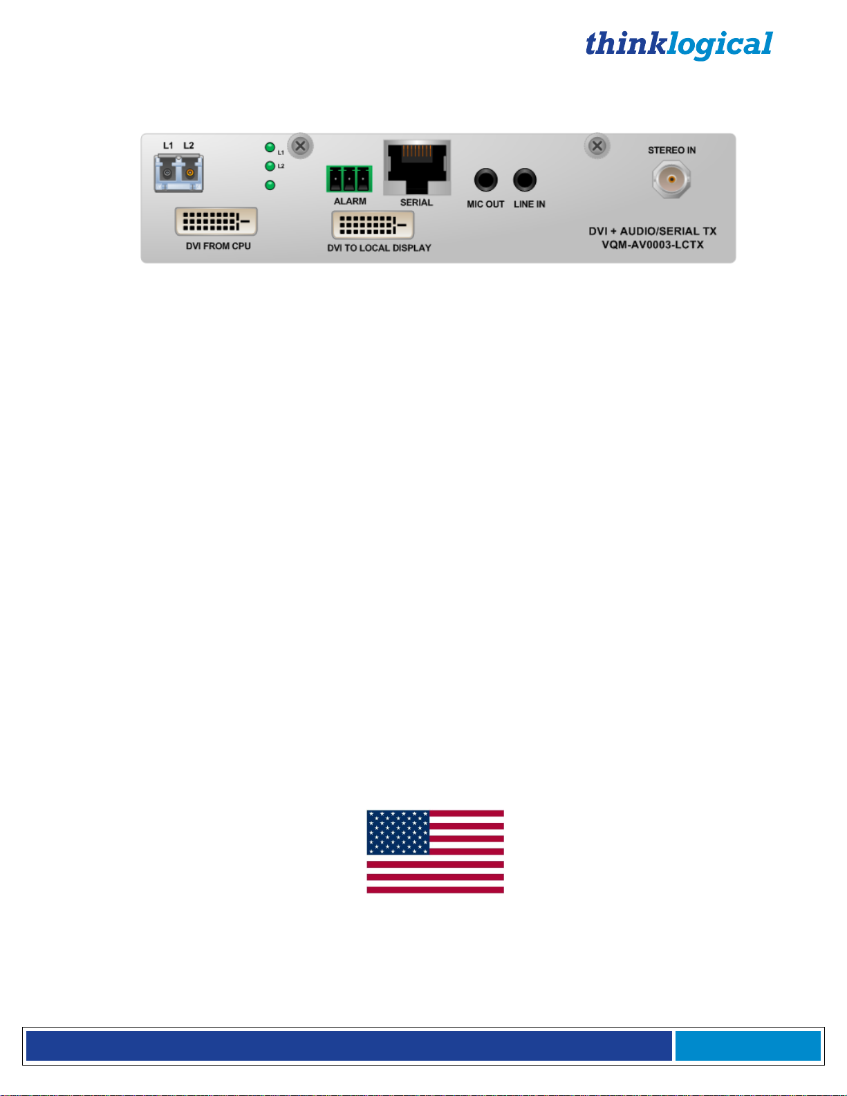
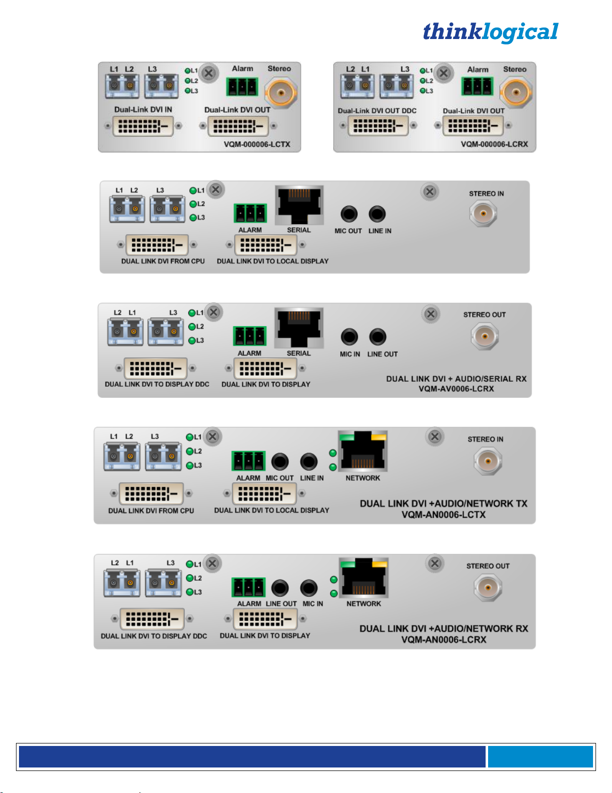
VQM-3 AV+ and VQM-3 AN+ Tx and Rx DVI Family of Modules:
VQM-3 AV+, TX Single Video, Audio, Serial
VQM-3 AV+, RX Single Video, Audio, Serial
VQM-3V AV+, TX Dual Video, Audio, Serial
Page 14
®
Q - S e r i e s V i d e o M o d u l e s P r o d u c t M a n u a l , R e v . I
Page 14
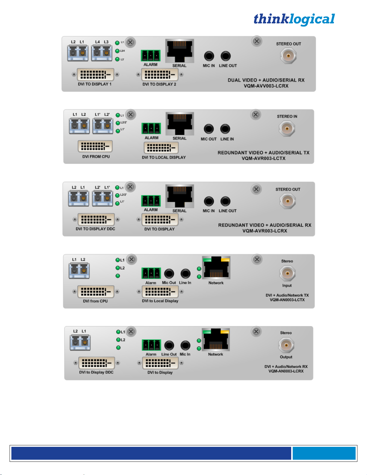
VQM-3V AV+, RX Dual Video, Audio, Serial
VQM-3R AV+, TX Redundant Video, Audio, Serial
VQM-3R AV+, RX Redundant Video, Audio, Serial
VQM-3 AN+, TX Single Video, Audio, Network
VQM-3 AN+, RX Single Video, Audio, Network
Page 15
®
Q - S e r i e s V i d e o M o d u l e s P r o d u c t M a n u a l , R e v . I
Page 15
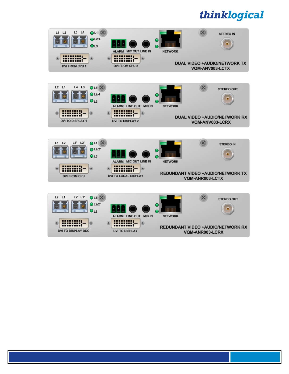
VQM-3V AN+, TX Dual Video, Audio, Network
VQM-3V AN+, RX Dual Video, Audio, Network
VQM-3R AN+, TX Redundant Video, Audio, Network
VQM-3R AN+, RX Redundant Video, Audio, Network
VQM-6, VQM-6 AV+ and VQM-6 AN+ Tx and Rx DVI Modules:
(Pictured on page 16)
VQM-6, VQM-6 AV+ and VQM-6 AN+ module features:
Supports all Single-Link and Dual-Link DVI video resolutions
MRTS technology 6.25Gbps allows for full frame rate transmission of uncompressed DVI
Signal transmission via fiber optic cable; no RF interference
Requires two or three fiber optic cables depending on application
Flawless image quality with no frame dropping
Local video port on the transmitter
Additional video output on the receiver
Audio and RS-232 serial ports (on AV+ models only)
Audio and Network ports (on AN+ models only)
DDC2B/EDID compliant
Simple plug and play
Page 16
®
Q - S e r i e s V i d e o M o d u l e s P r o d u c t M a n u a l , R e v . I
Page 16
VQM-6, TX Dual-Link Video VQM-6, RX Dual-Link Video
VQM-6 AV+, TX Dual-Link Video, Audio, Serial
VQM-6 AV+, RX Dual-Link Video, Audio, Serial
VQM-6 AN+, TX Dual-Link Video, Audio, Network
VQM-6 AN+, RX Dual-Link Video, Audio, Network
Page 17
®
Q - S e r i e s V i d e o M o d u l e s P r o d u c t M a n u a l , R e v . I
Page 17
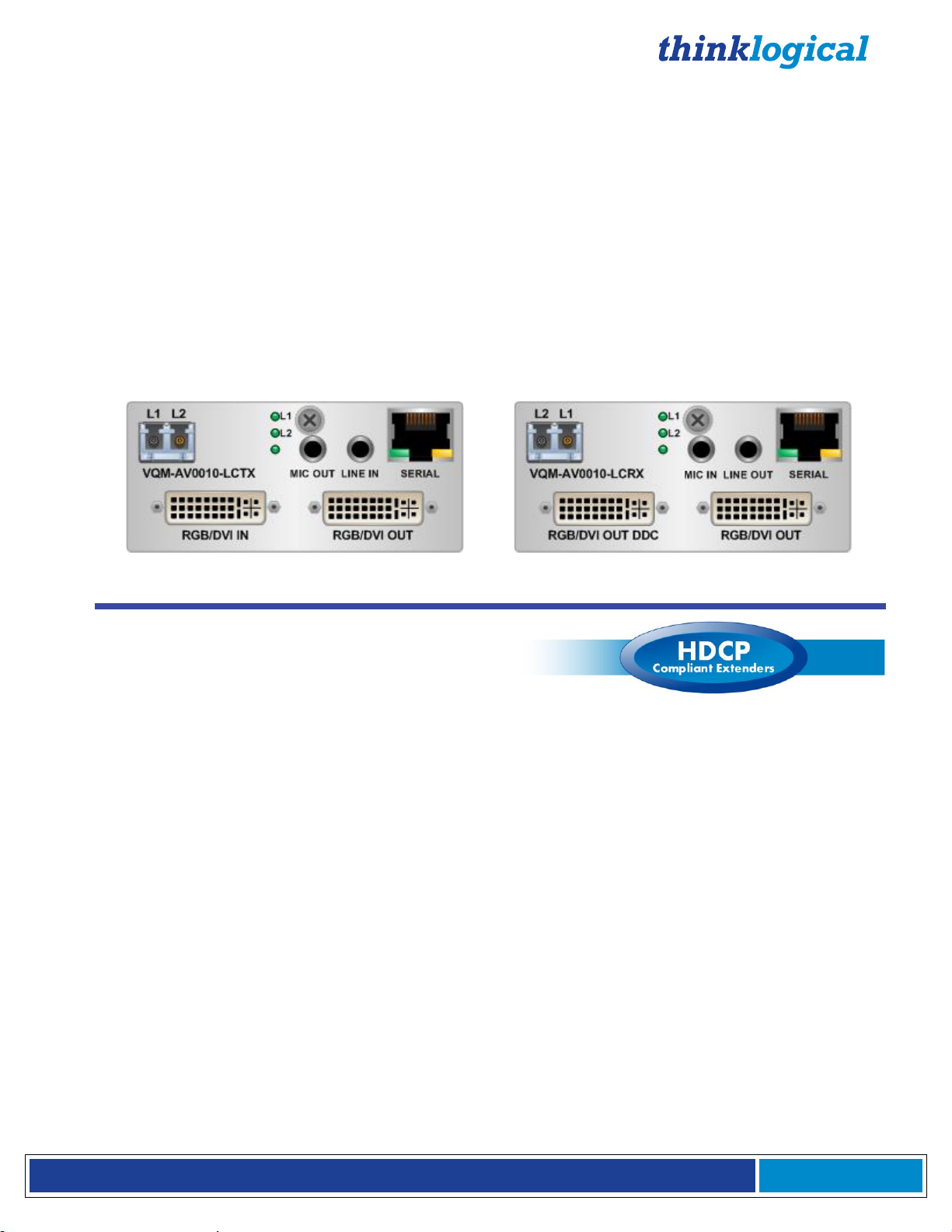
VQM-10 AV+ Tx and Rx RGB/DVI Modules:
VQM-10AV+ module features:
Supports all Single-Link DVI and most common RGB video resolutions
MRTS technology 6.25Gbps allows for full frame rate transmission of uncompressed RGB/DVI
Signal transmission via fiber optic cable; no RF interference
Requires one or two fiber optic cables depending on application
Flawless image quality with no frame dropping
Local video port on the transmitter
Additional video output on the receiver
Audio and RS-232 serial ports
DDC2B/EDID compliant
Simple plug and play
See Appendix B (page 35) for VQM-10 AV+ supported analog resolutions
See Appendix C (page 36-43) for VQM-10 AV+ Tx and Rx LCD Menu options
VQM-10 AV+, TX RGB/DVI Video VQM-10 AV+, RX RGB/DVI Video
4.2 Velocity Q-Series HDCP
Compliant Video Modules
Q-Series HDCP Compliant Video module features:
Supports all Single-Link DVI video resolutions
Fully HDCP compliant
MRTS technology 6.25Gbps allows for full frame rate transmission of uncompressed DVI
Signal transmission via fiber optic cable; no RF interference
Flawless image quality with no frame dropping
Audio and RS-232 serial ports (on AH models only)
Audio and Network ports (on NH models only)
Local video port on the transmitter (except on Dual Video models)
Additional video output on the receiver (except on Dual Video models)
DDC2B/EDID compliant
Simple plug and play
VQM-3H, VQM-3AH and VQM-3NH module features:
Requires one or two fiber optic cables depending on application
VQM-3HV, VQM-3AHV and VQM-3NHV (Dual Video) module features:
Requires two to four fiber optic cables depending on application
Audio and Network features are functional with the first video channel only
VQM-3AVS Scaler Receiver module features:
Automatically scales the video output format to the connected monitor’s preferred timing resolution
and supports up to 8 channels of embedded audio.
Page 18

®
Q - S e r i e s V i d e o M o d u l e s P r o d u c t M a n u a l , R e v . I
Page 18
4.2.1. Velocity Q-Series HDCP Compliant Module Part Numbers:
VQM-AH0003-LCTX/RX (A=Audio, H=HDCP capability)
VQM-NH0003-LCTX/RX (N=Network, H=HDCP capability)
VQM-0H0003-LCTX/RX (H=HDCP capability)
VQM-0HV003-LCTX/RX (V=Dual Video, H=HDCP capability)
VQM-0H0003-LCRX VQM-3, Single Link DVI, DDC, HDCP Compliant, RX, LC
VQM-0H0003-LCTX VQM-3, Single Link DVI, DDC, HDCP Compliant, TX, LC
VQM-AH0003-LCRX VQM-3 AV+, Single Link DVI, DDC, Audio, Serial, HDCP Compliant, RX, LC
VQM-AH0003-LCTX VQM-3 AV+, Single Link DVI, DDC, Audio, Serial, HDCP Compliant, TX, LC
VQM-NH0003-LCRX VQM-3 AV+, Single Link DVI, DDC, Audio, Network, HDCP Compliant, RX, LC
VQM-NH0003-LCTX VQM-3 AV+, Single Link DVI, DDC, Audio, Network, HDCP Compliant, TX, LC
VQM-NHV003-LCRX VQM-3 AVV+, Dual Single Link DVI, DDC, Audio, Network, HDCP Compliant, RX, LC
VQM-NHV003-LCTX VQM-3 AVV+, Dual Single Link DVI, DDC, Audio, Network, HDCP Compliant, TX, LC
VQM-0HV003-LCRX VQM-3V, Dual Single Link DVI, DDC, HDCP Compliant, RX, LC
VQM-0HV003-LCTX VQM-3V, Dual Single Link DVI, DDC, HDCP Compliant, TX, LC
VQM-AHV003-LCRX VQM-3 AVV+, Dual Single Link DVI, DDC, Audio, Serial, HDCP Compliant, RX, LC
VQM-AHV003-LCTX VQM-3 AVV+, Dual Single Link DVI, DDC, Audio, Serial, HDCP Compliant, TX, LC
VQM-AV00S3-LCRX VQM-3 AV+, Single Link DVI, DDC, Audio, Serial, HDCP Compliant, Scaler RX, LC
4.2.2. Velocity Q-Series HDCP Compliant Module Front Panel Views
Page 19

®
Q - S e r i e s V i d e o M o d u l e s P r o d u c t M a n u a l , R e v . I
Page 19
VQM-AHV003-LCTX/RX (A=Audio, H=HDCP capability, V=Dual Video)
VQM-NHV003-LCTX/RX (N=Network, H=HDCP capability, V=Dual Video)
DVI to Display
L2 L1
MIC IN LINE OUT
VQM-AV00S3-LCRX
SERIAL
HDCP
HDMI/DVI
LOS/HP
CTRL
VQM-AV00S3-LCRX (A=Audio, V=Video, S=Scaler)
Thinklogical’s Q-Series Scaler Receiver is HDCP compliant and automatically scales the video output format to the
connected monitor’s preferred timing resolution while supporting up to 8 channels of embedded audio. As with all
HDCP compliant models, the Scaler Receiver is available with LC-Type fiber connectors only. (See Appendix D:
VQM-3 Scaler Menu Options on page 44.)
All physical connections to the Q-Series Video Modules use industry-standard
connectors. Non-supplied cables that may be needed are commercially available.
All connections are found on each module’s front panel.
4.3 Fiber Connections to the Q-Series Video Modules
4.3.1. Single Fiber Operation, Single-Link Video
The unit will operate with a single fiber from the TX to the RX. In this mode of operation the TX
can transmit video and data to the RX over fiber L1. The RX cannot send any information to the
TX. Also, DDC information can only be gathered from the TX local port or the Thinklogical
default EDID table.
In this mode video information is transmitted from the TX to the RX over fiber L1. Fiber L2 is
used as a data return path from the RX to the TX. Providing a back channel from the RX to the
TX allows the RX to modify DDC configuration via the Front Panel LCD and buttons and allows
4.3.2. Dual Fiber Operation, Single-Link Video
Page 20

®
Q - S e r i e s V i d e o M o d u l e s P r o d u c t M a n u a l , R e v . I
Page 20
the RX to send DDC information to the TX. DDC information exchange allows the PC to gather
3.5mm 3.5mm
USB B USB A
DVI-D Single-Link Male DVI-D Single-Link Male
information about the connected monitor to determine the display properties.
4.3.3. Three and Four Fiber Operation, Dual Video
VQM-3HV and VQM-3AHV operate in Dual-fiber or Quad-fiber modes. In Dual-Fiber operation,
fibers L1 and L3 are used to transmit data and video from the TX to the RX and in Quad-Fiber
mode, fibers L2 (video head 1 DDC) and L4 (video head 2 DDC) transmit data from the RX back
to the TX.
4.3.4. Two and Four Fiber Operation, Redundant Video
VQM-3R operates in Dual-fiber or Quad-fiber modes. In dual-fiber operation, fibers L1 and L1’
are used to transmit data and video from the TX to the RX and in Quad-fiber mode, fibers L2
and L2’ transmit data from the RX back to the TX. L1’ and L2’ are copies of L1 and L2
respectively.
4.3.5. Two and Three Fiber Operation, Dual-Link Video
VQM-6 operates in Dual-fiber or Triple-fiber modes. In dual-fiber operation, fibers L1 and L3 are
used to transmit data and video from the TX to the RX. In three-fiber mode, fiber L2 transmits
data from the RX back to the TX.
4.4. Supplied Cables
Depending on the customer-specified system configuration, power, video and peripheral cables from the
following list will be supplied by Thinklogical in quantities specific to each configuration:
4.4.1 3.5mm to 3.5mm Audio Cable, 6 Feet (CBL000016-006FR)
4.4.2 USB A-B Cable, 6 Feet (CBL000015-006FR)
4.4.3. DVI-D Single-Link, 2 Meters (CBL000009-002MR)
Page 21

®
Q - S e r i e s V i d e o M o d u l e s P r o d u c t M a n u a l , R e v . I
Page 21
4.4.4. DVI-D Dual-Link, 2 Meters (CBL000023-002MR)
DVI-D Dual-Link Male DVI-D Dual-Link Male
BNC BNC
RJ45 RJ45
VGA Male DVI-A Male
USE ONLY
WITH 250V
FUSE
4.4.5. BNC Male to Male, 50Ω, 6 Feet (CBL000018-006FR)
4.4.6. RJ45M to RJ45M CAT5, 2 Meters (CBL000001-002M)
4.4.7. VGA Male to DVI-A Male, 2 Meters (CBL000022-002MR)
4.4.8 . Domestic AC Power Cord (PWR-00006-R)
Page 22

®
Q - S e r i e s V i d e o M o d u l e s P r o d u c t M a n u a l , R e v . I
Page 22
4.4.9. Adapters: RJ45 to DB9F (ADP-000025), RJ45 to DB9M (ADP-000019)
RJ45 to
DB9F ADPT
ADP-000025
RJ45 to
DB9M ADPT
ADP-000019
USB Mini-B USB A
Normally Closed Common Normally Open
ALARM
4.4.10. The USB Mini-B to USB-A User Configuration Control Cable (CBL000105-
002MR), for use with scaler models housed in a Q-1300 Chassis, is available
from Thinklogical. Please contact your sales representative.
4.5 Dry Contact Alarm
Dry contact alarms are located on each of the individual modules. The relay is energized when there is
an alarm condition, such as over temperature or power regulation.
The dry contact alarm is a Form C contact with the following ratings:
Nominal switching capacity: 1A, 30V DC
Max. switching power: 30W DC
Dry Contact Alarm Receptacle
Page 23

®
Q - S e r i e s V i d e o M o d u l e s P r o d u c t M a n u a l , R e v . I
Page 23
4.6 Q-Series Modules’ Audio Specifications
Audio Sampling Rate
46.875 kHz
Transmitter
Line Input Impedance: 10KΩ
Maximum Line Input: 2.5 volts peak to peak
Microphone Output Impedance: 300Ω
Maximum Microphone Output: 0.45 volts peak to peak
Receiver
Line Output Impedance: 560Ω
Maximum Output: 3 volts peak to peak
Microphone Input Impedance: 5KΩ
Maximum Microphone Input: 0.24 volts peak to peak
Module Specifications
Power Consumption: 10 watts per unit
VQM-3, VQM-3A,
VQM-3N, VQM-3R, VQM-
3H, VQM-3AH, VQM-3AVS,
VQM-3NH, VQM-3V, VQM-
3HV, VQM-AHV,
VQM-6, VQM-10AV+
Dimensions:
Height: 1.592” (40.43 mm)
Depth: 6.366" (161.69 mm)
Width: 3.693" (93.80 mm)
(Tolerance: ± .039"; 1 mm)
VQM-3 AV+
VQM-3AN+
VQM-6 AV+
VQM-6AN+
Dimensions:
Height: 1.592” (40.43 mm)
Depth: 6.366” (161.69 mm)
Width: 7.406" (188.11 mm)
(Tolerance: ± .039"; 1 mm)
Electrical Cables
(supplied with transmitters)
KIT-000005-R Audio Kit 1 (contains the following):
CBL000006-006FR 6 Pin Mini-DIN, Male to Male Cable, 6FT (2)
CBL000015-006FR USB A-B Cable, 6FT (2)
CBL000016-006FR 3.5mm Male to 3.5mm Male Plug, 6FT (2)
CBL000017-006FR DB9M to DB9F Cable, 6FT (1)
CBL000018-006FR BNC Male to BNC Male Cable, 50Ω, 6FT (1)
DB9 to RJ45 Adapters
With AV+ models only:
ADP-000019-R DB9M to RJ45
ADP-000025-R DB9F to RJ45
Copper Video Cables
CBL000009-002MR Single-link DVI-D Male to Male, 2
meters
1 each, VQM-3, VQM-3 AV+, VQM-3 AN+
2 each, VQM-3V, VQM-3V AV+, VQM-3V AN+
CBL000013-002MR DVI-I Male to DVI-I Male, 2 meters
1 each, VQM-10AV+
CBL000022-002MR DVI Male to VGA Male, 2 meters
1 each, VQM-10AV+
CBL000023-002MR Dual-link DVI-D Male to Male, 2 meters
1 each, VQM-6, VQM-6 AV+, VQM-6 AN+
4.7 Q-Series Video Modules’ Technical Specifications
Page 24

®
Q - S e r i e s V i d e o M o d u l e s P r o d u c t M a n u a l , R e v . I
Page 24
Optical Distance
Multi-Mode:
Up to 50 meters with Type OM1
Up to 350 meters with Type OM2
Up to 750 meters with Type OM3
Up to 1000 meters with Type OM4
Single Mode: Up to 80km with Type OS2 9/125 for all distances
Supply Voltage
100-240 VAC, 47-63 Hz, Universal AC power supply
Operating Temp
and Humidity
0° to 50°C (32° to 122 °F), 5% to 95% RH, non-condensing
Compliance
Approvals for US, Canada, and European Union
Warranty
12 months from date of purchase. Extended warranties
available.
4.8 Status Indicator LEDs
The LED Status Indicators on the Q-Series modules are provided as troubleshooting aides in diagnosing
and resolving technical problems so that a technician can easily assess the status of the module.
The LEDs on most devices monitor the status of the fibers at L1-L4 and are labeled as such. The
functions of the fiber LEDs are described on page 25.
4.8.1. Scaler Receiver Status LEDs
The LEDs on the Scaler Receiver indicate whether the device is receiving HDCP, HDMI or DVI video
signals and if the unit detects an input signal or Hot Plug (a monitor’s output signal that lets the video
source know if a new monitor has been connected so it can read the DDC table). The Scaler Receiver
LED functions are described below.
Page 25

®
Q - S e r i e s V i d e o M o d u l e s P r o d u c t M a n u a l , R e v . I
Page 25
4.8.2. Q-Series Video Module Tx and Rx Status LEDs
L1
L2/L4
L3
Transmitter Fiber Status LEDs (Dual Video)
L1
L2 and/or L4
LED OFF FLASHING ON STEADY
No SFP
Fiber Active,
No DVI 1
Return Path
Locked
L3 No SFP
Receiver Fiber Status LEDs (Dual Video)
L1
L2 and/or L4
LED OFF FLASHING ON STEADY
Not Locked
Locked,
No DVI 1
Fiber Active
L3
No SFP
Not Locked
Fiber Status LEDs:
The LED status indicators on the Q-Series modules are provided as troubleshooting aides in diagnosing
and resolving technical problems so that a technician can easily assess the status of the module.
All transmitter and receiver LEDs are GREEN (with the exception of the Activity LED on the RJ45 port on
Network models) and can be in one of three states: OFF, FLASHING, or ON.
In the case of dual or redundant video modules, both return fibers are monitored by LEDs L2 and L4 (dual video)
or L2 and L2' (redundant video) and will operate the same if only one or both of these fibers is detected. LEDs
L1 and L3 are mutually-exclusive from each other with ONE exception –
ALL LEDS FLASHING IN UNISON INDICATES THAT THE MODULE IS IN ALARM!
A module will be declared in ALARM if any of the following conditions exist:
Over the maximum temperature threshold (module or chassis)
Wrong or missing voltage
Bad firmware checksum value
LEDs Off:
NO SFP – The SFP is missing or not seated properly in the socket
NOT LOCKED – The SFP and a signal are present but not locked to the source.
Transmitter:
RETURN PATH LOCKED – The return signal is present and locked to the source.
FIBER ACTIVE, NO DVI 1, 2 – Valid data path but no DVI
FIBER ACTIVE, DVI 1, 2 VALID – Valid data path and valid DVI
Receiver:
FIBER ACTIVE – A valid return signal is present
LOCKED, NO DVI 1 & 2 – Data is present, but no DVI
LOCKED, DVI 1 & 2 VALID – Data and valid DVI present
Network Status LEDs:
On the RJ45 Port:
Yellow LED Flashing = Activity
Green LED on = Link
10/100:
On when speed of link is 100 Mb/sec.
Off when speed of link is 10 Mb/sec.
FD/COL:
On when operating in Full Duplex.
Off when operating in Half Duplex.
Flashing indicates Collision.
NETWORK
Fiber Active,
DVI 1 Valid
Locked,
DVI 1 Valid
Locked,
No DVI 2
Locked,
DVI 2 Valid
Not Locked
Fiber Active,
No DVI 2
Fiber Active,
DVI 2 Valid
Page 26

®
Q - S e r i e s V i d e o M o d u l e s P r o d u c t M a n u a l , R e v . I
Page 26
4.9 Firmware and FPGA Updates
Upgrades are available through Thinklogical®. For technical assistance, please call us at:
1-203-647-8700.
To update the Chassis firmware, use the KM Download Procedure described below.
Firmware Upgrade:
USB Cable from CPU to UPDATE Port Front panel LCD
KM Download Procedure:
Firmware files are stored in the following:
http://ftp.thinklogical.com/ftp/visualization/updates/Firmware.zip
The KM_Download.exe application and instructions are stored in:
http://ftp.thinklogical.com/ftp/visualization/updates/KmDownload.zip
Firmware Update Preparation:
1. Retrieve the Firmware Files and the KM_Download application/instructions and place
them in an accessible directory in your CPU.
2. Install the KmDownload application (in KMDownload.zip file) by running setup.exe.
3. Unzip the Firmware.zip file and place the contents in an accessible directory in your CPU.
4. Have a copy of the instructions and latest versions available for comparison after the update is
complete.
To update a module’s FPGA, go to Allow FPGA Update under the *System menu (front panel LCD).
Select Yes and load the update through the front panel USB port using the FPGA Update, as described
below:
FPGA Download Procedure:
Firmware files are stored in the following:
http://ftp.thinklogical.com/ftp/visualization/updates/FPGA_Firmware.zip
The FPGA_Download.exe application & instructions are stored in:
http://ftp.thinklogical.com/ftp/visualization/updates/FPGA_Upgrade.zip
FPGA Update Preparation:
1. Retrieve the Firmware Files and the FPGA_Download application /instructions and place
them in an accessible directory in your CPU.
2. Copy the file FPGA_Firmware.zip to a local directory and extract to a desired location.
3. Copy the file FPGA_upgrade.zip to a local directory.
4. Install setup.exe in FPGA_upgrade.zip.
5. Have a copy of the instructions and latest versions available for comparison after the update is
complete.
Page 27

®
Q - S e r i e s V i d e o M o d u l e s P r o d u c t M a n u a l , R e v . I
Page 27
5. Regulatory & Safety Compliance
5.1 Safety Requirements
Symbols found on the product
Markings and labels on our product follow industry-standard conventions. Regulatory markings found on
our products comply with domestic and many international requirements.
Regulatory Compliance
Thinklogical’s® products are designed and made in the U.S.A. These products have been tested by a
certified testing laboratory and found to be compliant with the following standards (both domestic USA
and many international locations):
North America
Safety
ANSI/UL60950-1: 1st Edition (2003)
CAN/CSA C22.2 No. 60950-1-03
Electromagnetic Interference
FCC CFR47, Part 15, Class A
Industry Canada ICES-003 Issue 2, Revision 1
Australia & New Zealand
This is a Class A product. In a domestic environment this product may cause radio interference, in
which case the user may be required to take adequate measures.
European Union
Declaration of Conformity
Manufacturer’s Name & Address: Thinklogical, LLC®
100 Washington Street
Milford, Connecticut 06460 USA
These products comply with the requirements of the Low Voltage Directive 72/23/EEC and the EMC
Directive 89/336/EEC.
Standards with Which Our Products Comply
Safety
CENELEC EN 60950-1, 1st Edition (2001)
Electromagnetic Emissions
EN55022: 1994 (IEC/CSPIR22: 1993)
EN61000-3-2/A14: 2000
EN61000-3-3: 1994
Electromagnetic Immunity
EN55024: 1998 Information Technology Equipment-Immunity Characteristics
EN61000-4-2: 1995 Electro-Static Discharge Test
EN61000-4-3: 1996 Radiated Immunity Field Test
EN61000-4-4: 1995 Electrical Fast Transient Test
EN61000-4-5: 1995 Power Supply Surge Test
EN61000-4-6: 1996 Conducted Immunity Test
EN61000-4-8: 1993 Magnetic Field Test
EN61000-4-11: 1994 Voltage Dips & Interrupts Test
Page 28

®
Q - S e r i e s V i d e o M o d u l e s P r o d u c t M a n u a l , R e v . I
Page 28
5.2. Supplementary Information
The following statements may be appropriate for certain geographical regions and might not apply to
your location.
This Class A digital apparatus meets all requirements of the Canadian Interference-Causing
Equipment Regulations.
Cet appareil numérique de la classe A respecte toutes les exigencies du Règlement sur le matérial
brouilleur du Canada.
Warning! This is a Class A product. In a domestic environment, this product may cause
radio interference, in which case the user may be required to take corrective measures.
Note: This equipment has been tested and found to comply with the limits for a Class A
digital device, pursuant to part 15 of the FCC Rules. These limits are designed to provide
reasonable protection against harmful interference when the equipment is operated in a
commercial environment. This equipment generates, uses and can radiate radio
frequency energy and, if not installed and used in accordance with the instruction
manual, may cause harmful interference to radio communications in which case the user
may be required to take adequate corrective measures at their own expense.
Note: This Class A digital apparatus complies with Canadian ICES-003 and has been
verified as being compliant within the Class A limits of the FCC Radio Frequency Device
Rules (FCC Title 47, Part 15, Subpart B CLASS A), measured to CISPR 22: 1993 limits and
methods of measurement of Radio Disturbance Characteristics of Information
Technology Equipment.
Note:
magnetic fields
The user may notice degraded audio performance in the presence of electro-
.
Product Serial Number
Thinklogical products have a unique serial number, which includes a date-code, printed on an adhesive
label that is affixed to the unit. The format for the date-code is 2 digits for the month, dash, 2 digits for the
year, plus at least four digits for a unique unit number. 05-140125 for example, indicates the unit was
built in the 5th month of 2014, and is unit number 125.
Connection to the Product
Connections and installation hardware for our products use industry-standard devices and methods. All
wiring connections to the customer equipment are designed to minimize proprietary or customized
connectors and cabling. Power connections are made with regionally appropriate power cords and
approved methods.
6. How to Contact Us
6.1. Customer Support
Thinklogical® is an engineering company and you will receive any information you need
directly from our most knowledgeable engineers.
We believe that the first line of support comes from the design engineers that
developed each particular product.
Therefore, your questions or issues will be handled promptly by our in-house engineers who are
most familiar with your products. We won’t be satisfied until you’re satisfied.
Page 29

®
Q - S e r i e s V i d e o M o d u l e s P r o d u c t M a n u a l , R e v . I
Page 29
Thank you for choosing Thinklogical® products for your application.
We appreciate your business and are dedicated to helping you successfully use our products.
is always here to help you.
To contact us, please use the following telephone numbers and internet-based methods:
®
Website
Check out our website for current product offerings, support information and general information about
all of the products we offer.
Our internet website offers product information on all current systems, including technical specification
sheets and installation guides (for viewing online or for download), product diagrams showing physical
connections and other information you might need.
Internet: www.thinklogical.com
Note: Most online documents are stored as Adobe Acrobat “PDF” files. If you do not have
the Adobe Acrobat reader needed to view PDF files, visit www.adobe.com for a download.
Email
Thinklogical is staffed Monday through Friday from 8:30am to 5:00pm, Eastern Time Zone. We will
do our best to respond to your email inquiries promptly. Please use the following email addresses:
info@thinklogical.com – Information on Thinklogical® and our products.
sales@thinklogical.com – Sales Department - orders, questions or issues.
support@thinklogical.com – Product support, technical issues or questions, product
repairs and request for Return Authorization.
Telephone
Product & Customer Support: 1-203-647-8700
US Commercial & Canada Sales: 1-203-647-8769
US Federal Government Sales: 1-203-647-8716
Toll Free in the Continental US: 1-800-291-3211
International Sales (Europe, Middle East, Africa): 1-203-647-8704
International Sales (Asia Pacific, Central & Latin America): 1-203-647-8734
Fax: 1-203-783-9949
Please contact our expert sales staff in Milford, CT. We are here Monday through Friday from 8:30am to
5:00pm, Eastern Time Zone. We’ll provide a representative’s direct dial phone number when you call.
If leaving a voice message, please provide a preferred time to call back so we may reach you at your
convenience.
Our switchboard attendant will direct your call during regular business hours. We have an automated
attendant answering our main telephone switchboard after regular business hours and holidays. You can
leave voice messages for individuals at any time.
Fax
Our company facsimile number is 1-203-783-9949. Please indicate the nature of the fax on your cover
sheet and provide return contact information.
Page 30

®
Q - S e r i e s V i d e o M o d u l e s P r o d u c t M a n u a l , R e v . I
Page 30
6.2. Product Support
If you need to return your Thinklogical® product to us for any reason, please get a
Return Merchandise Authorization Number (RMA#)
from Thinklogical’s Product Support Department (1-203-647-8700) before sending the unit in.
Thinklogical’s support personnel are available Monday through Friday from 8:30am to 5:00pm,
Eastern Time Zone. If your application requires assistance at some time outside of our normal business
hours, please contact us beforehand and we will do our best to make arrangements to help you with your
Thinklogical products.
6.2.1. Warranty
Thinklogical, LLC® warrants this product against defects in materials and workmanship for a period of
one year from the date of delivery. Thinklogical and its suppliers disclaim any and all other warranties.
Note: Thinklogical, LLC products carry a one year warranty, with longer term available at
time of purchase on most products. Please refer to your product invoice for your product’s
Warranty Terms & Conditions.
Defect remedy shall be the repair or replacement of the product, provided that the defective product is
returned to the authorized dealer within a year from the date of delivery.
If you wish to return your device, contact the Thinklogical authorized dealer where you purchased the
device, or if you purchased directly, call Thinklogical at 1-800-291-3211 (USA).
6.2.2. Return Authorization
In the event you must return a product to Thinklogical directly, please contact Customer Support at 1800-291-3211 or 1-203-647-8700. Customer Support will ask you to describe the problem and will issue
you a Return Merchandise Authorization number (RMA#). Pack the device in its original box, if possible,
and return it with the RMA# printed on the outside of the box.
Note: DO NOT return a product to Thinklogical® without a Return Material Authorization.
Our Addresses
If you have any product issues or questions or need technical assistance with your Thinklogical system,
please call us at 1-800-291-3211 (USA only) or 1-203-647-8700 and let us help. If you need to write us
or return a product with a Return Material Authorization, please use the following address:
Thinklogical, LLC®
Attn: RMA#
100 Washington Street
Milford, CT 06460 USA
Website: www.thinklogical.com
Facebook: www.facebook.com/ThinklogicalUSA
LinkedIn: www.linkedin.com/company/thinklogical
Google+: http://plus.google.com/u/0/109273605590791763795/about
YouTube: www.youtube.com/user/thinklogicalNA
Twitter: @thinklogical
Page 31

®
Q - S e r i e s V i d e o M o d u l e s P r o d u c t M a n u a l , R e v . I
Page 31
Local
DVI OUT
Module 1
Local
DVI OUT
Module 2
Local
DVI OUT
Module 3
Local
DVI OUT
Module 4
DVI OUT DDC
Module 1
DVI OUT DDC
Module 2
DVI OUT DDC
Module 3
DVI OUT DDC
Module 4
DVI IN
Module 4
DVI IN
Module 3
DVI IN
Module 2
DVI IN
Module 1
Source CPU
L1: Data TX to RX and Video
L2: Data RX to TX
External Control CPU
Network Hub
7
Optional Secondary
Controller Card
IP address: 192.168.13.116
Primary Controller
Card IP Address:
192.168.13.115
As used with the
Q-Series Single-Link
Fiber-Optic Extension
System
2
1
3
4
6
STEP 6: Connect a DVI cable from the Source CPU
to the DVI IN port of each Transmitter Module. If
desired, connect an optional local monitor to each
of the Transmitters’ DVI OUT ports with a standard
DVI cable. If stereo 3-D molecular visualization at
the destination is desired, connect the Stereo
Source’s OUTPUT to the Transmitter Module’s
STEREO INPUT.
Ensure the sources are turned ON.
8
STEP 7: Connect the Controller Cards’ LAN Ports
to your Controller CPU with CAT5 cables.
(CPU IP address: 192.168.13.9)
STEP 8: Connect both supplied AC Power Cords
(PWR-0000056-R) to the receptacles located on the
VX160's power supplies. Plug each one into a
standard AC source. Verify that all system functions
are operating properly.
DVI OUT
Module 1
DVI OUT
Module 2
DVI OUT
Module 3
DVI OUT
Module 4
3D Stereo Emitter
STEP 1: Connect the Q-Series Receiver Modules
to the VX160 using multi-mode fiber-optic cables
(up to 1000 meters). Connect fiber L1 to any SFP’s
Transmit Port and fiber L2 to the same SFP’s
Receive Port. Do the same for each of the Receiver
modules.
STEP 2: Ensure the Q-4300 Power Supply
switches on the front panel are in the OFF position.
Install the Right Power Supply Module AC Power
Cord (left receptacle) and the Left Power Supply
Module AC Power Cord (right receptacle) onto the
Q-4300 Chassis. Plug both cords into a standard
AC source. On the front of the chassis, turn ON the
Right and Left Power Supply Modules.
STEP 3: Connect a monitor to each of the DVI OUT
DDC ports with a standard DVI cable. A second,
non-DDC monitor may also be connected to each
modules’ DVI OUT port. If stereo 3-D molecular
visualization on your desktop is desired, connect a
3-D Active Stereo Emitter to the STEREO OUT
receptacle on the Receive module.
STEP 4: Connect the Q-Series Transmitter
Modules to the VX160 using multi-mode fiber-
optic cables (up to 1000 meters). Connect fiber
L1 to any SFP’s Receive Port and fiber L2 to the
same SFP’s Transmit Port. Do the same for each
of the four Transmitter modules.
STEP 5: Ensure the Q-4300 Power Supply
switches on the front panel are in the OFF
position. Install the Right Power Supply Module
AC Power Cord (left receptacle) and the Left
Power Supply Module AC Power Cord (right
receptacle) onto the Q-4300 Chassis. Plug each
cord into a standard AC source. On the front of the
chassis, turn ON the Right and Left Power Supply
Modules.
VQM-3 Transmitters (4)
VQM-000003-LCTX
Q-4300 Chassis
VQS-004300
VQM-3 Receivers (4)
VQM-000003-LCRX
Q-4300 Chassis
VQS-004300
VX160 Router Chassis
VXR-000160
16 Rack Units, 850 Watts
Upstream Data Card (8)
VXM-DI0020
Downstream Data Card (8)
VXM-DO0020
Controller Card (2)
VXM-000001
QUICK-START GUIDE
QUICK-START GUIDE
KVM Matrix Switch
Powered by
MRTS Technology
VX160
router
Complete Steps 1-8 to connect
to a VX160 KVM Matrix Switch
®
5
3D Stereo
Emitter
Tx
Rx
SFP
Tx
Rx
SFP
Appendix A- Quick Start Guides
Page 32

®
Q - S e r i e s V i d e o M o d u l e s P r o d u c t M a n u a l , R e v . I
Page 32
DVI OUT 2
VQM-2 Dual
Video
DVI OUT 2
VQM-3V Dual
Video
QUICK-START GUIDE
QUICK-START GUIDE
As used with Thinklogical’s® Q-Series and
Velocitydvi-3 Video Extension Systems
Complete Steps 1-8 to connect to the VX80 Router:
STEP 1: Connect the VQM-3V Receiver Modules to the VX80
Router using multi-mode fiber-optic cables (up to 1000 meters).
Connect fiber L1 to any Downstream SFP’s Transmit Port and fiber
L2 to the same SFP’s Receive Port.
STEP 2: Ensure the Q-4300 Power Supply switches on the front
panel are in the OFF position. Install the Right Power Supply
Module AC Power Cord (left receptacle) and the Left Power
Supply Module AC Power Cord (right receptacle) onto the Q-4300
Chassis. Plug each cord into a standard AC source. On the front of
the chassis, turn ON the Right and Left Power Supply Modules.
On the VelocityDVI Receiver, connect the +5VDC Adapter (PWR-
000022-R) to the unit and plug it into a standard AC source.
STEP 4: Connect the VQM-3V Transmitter Modules to the
VX80 Router using multi-mode fiber-optic cables (up to 1000
meters). Connect fiber L1 to any Upstream SFP’s Receive Port
and fiber L2 to the same SFP’s Transmit Port.
STEP 5: Ensure the Q-4300 Power Supply switches on the
front panel are in the OFF position. Install the Right Power
Supply Module AC Power Cord (left receptacle) and the Left
Power Supply Module AC Power Cord (right receptacle) onto
the Q-4300 Chassis. Plug each cord into a standard AC source.
On the front of the chassis, turn ON the Right and Left Power
Supply Modules.
STEP 6: Connect DVI cables from the Source CPUs to the DVI
IN ports of each Transmitter. Connect the Stereo 3D sources
from the CPU to the Transmitters with standard BNC cables.
Ensure the CPUs are turned ON.
STEP 7: Connect the VX80 Controller Cards’ LAN Ports to
your Controller CPU with CAT5 cables.
(CPU IP address: 192.168.13.9)
STEP 8: Connect both supplied AC Power Cords
(PWR-0000006-R) to the receptacles located on
the VX80's power supplies. Plug each one into a
standard AC source. Verify that all system functions
are operating properly.
VX80_VQM-3V_to_VQM-3V_VEL-3_QSG_manual
with VQM-3V Dual Video Transmitter & Receiver Modules
VQM-3V Dual-Video Tx
VQM-00V003-LCTX
2
8
Q-4300 Chassis
VQS-004300
VX80 Router KVM Matrix Switch Chassis, 6 Rack Units, 400 Watts
DVI IN 1
Source CPUs 7 & 8
VQM-3V Dual Video Rx
VQM-00V003-LCRX
Q-4300 Chassis
VQS-004300
DVI OUT 1
VQM-3V
Dual Video 1
DVI OUT 2
VQM-3 Dual
Video
DVI OUT 1
VQM-3V
Dual Video 3
DVI OUT 1
VQM-3V
Dual Video 4
3
L1: Data TX to RX and Video
L2: Data RX to TX
DVI OUT 1
VQM-3V
Dual Video 2
DVI IN 2
DVI IN 1
Source CPUs 5 & 6
DVI IN 2
DVI IN 1
Source CPUs 3 & 4
DVI IN 2
DVI IN 1
Stereo 3-D
Source CPUs 1 & 2
6
DVI IN 2
Stereo 3-D
Stereo 3-D
Stereo 3-D
4
Network Hub
Optional Secondary Controller Card
IP address: 192.168.13.16
Primary Controller Card
IP Address: 192.168.13.15
External Control CPU
7
To LAN Ports
3D OUT 1 3D OUT 2 3D OUT 3 3D OUT 4
DVI OUT 2
VQM-3V
4 (DDC)
DVI OUT 2
VQM-3V
Dual Video 4
1 2 3 4
1 2 3 4
PWR-000022-R
2
3
1
VelocityDVI-3 Rx
VEL-000M03-LCRX
DVI OUT 2
VQM-3 Dual
Video
5
STEP 3: Depending on the
configuration, connect the
peripheral devices (monitors,
Stereo 3D, etc.) to the Receivers
using standard copper cables.
Turn all the devices ON.
KVM Matrix Switch
Powered by
MRTS Technology
VX80
router
Page 33

®
Q - S e r i e s V i d e o M o d u l e s P r o d u c t M a n u a l , R e v . I
Page 33
Page 34

®
Q - S e r i e s V i d e o M o d u l e s P r o d u c t M a n u a l , R e v . I
Page 34
Page 35

®
Q - S e r i e s V i d e o M o d u l e s P r o d u c t M a n u a l , R e v . I
Page 35
Appendix B. Thinklogical VQM-10 AV+ Supported Analog Resolutions
Active Resolution
Total
Lines
Vertical
Freq (Hz)
Horizontal
Freq (kHz)
Pixel Clock
Freq (MHz)
Video Standard
Pixels
Lines
640
448
472
66
31.2
25
Honeywell
640
480
525
60
31.5
25.175
Industry Standard
640
480
520
72
37.9
31.5
VESA
640
480
500
75
37.5
31.5
VESA
640
480
509
85
43.3
36
VESA
720
400
449
70
31.5
28.32
Industry Standard
800
600
625
56
35.1
36
VESA
800
600
628
60
37.9
40
VESA
800
600
666
72
48.1
50
VESA
800
600
625
75
46.9
49.5
VESA
800
600
631
85
53.7
56.25
VESA
1024
768
800
50
40
53.44
Folsom
1024
768
806
60
48.4
65
VESA
1024
768
800
75
60
78.75
VESA
1024
768
808
85
68.7
94.5
VESA
1280
720
750
50
37.5
74.25
Folsom
1280
720
750
60
45
74.25
CEA-861-E
1280
800
828
60
49.7
83.46
VESA GTF
1280
1024
1066
50
52.8
89.55
Folsom
1280
1024
1066
60
64
108
VESA
1280
1024
1082
60
64.8
108.88
Discreet
1280
1024
1066
75
80
135
VESA
1280
1024
1072
85
91.1
157.5
VESA
1280
1024
1063
96
102
163.277
SGI Onyx2
1366
768
795
60
47.7
85.5
VESA GTF
1400
1050
1090
50
54.5
94.61
Folsom
1400
1050
1080
60
64.8
120.78
VESA CVT-RB
1400
1050
1089
60
65.3
121.75
VESA
1400
1050
1099
96
105.4
164.5
SGI Stereo
1440
900
932
60
55.8
106.4
VESA GTF
1440
900
934
60
55.9
106.5
VESA DMT
1600
1200
1250
60
75
162
VESA
1680
1050
1089
60
65.3
146.25
VESA DMT
1920
1080
1125
25
28.12
74.25
Folsom
1920
1080
1125
50
56.25
148.5
Folsom
1920
1080
1125
60
67.5
148.5
CEA-861-E
Page 36

®
Q - S e r i e s V i d e o M o d u l e s P r o d u c t M a n u a l , R e v . I
Page 36
Appendix C:
Thinklogical
Velocity TX10 V22.04
*System
LS Connected
Yes/No. = No
Load Defaults
Yes/No. = No
Store Values
Yes/No. = No
NO Low Speed Data Channel Connection
YES
Modifiable
Description
VQM-10AV+ TX Front Panel LCD Display
Scroll Right or Left within the *System menu
Displays current revision. (Scroll Up or Down to
access top level *Menus.)
NO
NO
YES
NO
TX Cntrl. Version
Rev.= 22.04
RX Ctrl. Version
Name = Unknown
Serial Number
S/N. = _ _ _ _ _ _ _ _ _ _ _ _ _
Debug Values
Yes/No. = No
Customer can choose to load video parameters from factory
default settings
Will save current edited video parameters
Current control code revision
Connected receiver’s control code revisio n
Reserved for manufacturing test use
NO This unit’s serial number
Video FPGA Device ID
0x4100
Video FPGA Version
0x4.1.02
Main FPGA Device ID
0x2400
Main FPGA Version
x0.0.05
LS Des OK Signal
1
LS LOSS of Signal
1=0 2=0
Temp in Celsius
Tb= 32C Tf=37C
ALARMS TEMP
0
NO Temperature of PC Board (Tb) and FPGA (Tf)
NO Low Speed Deserializer Signal: 1=OK, 0=NO
NO Loss Of Low Speed Signal: 0=OK, 1=NO
NO 0=No Temperature Alarm, 1=Temperature Alarm
NO Identifies the installed Video FPGA device
NO Ma in FPGA Device’s currently installed revision
NO Identifies the currently installed Main FPGA version
NO Identifies the installed Main FPGA Device
Page 1 of 8, Appendix C
Thinklogical VQM-10 AV+ LCD Menu Options (Q-2300 & Q-4300 Chassis) *
*Q-Series LCD menus operate the same as on VelocityRGB-10AV+ Stand-Alone units.
Transmitter LCD Menus:
Page 37

®
Q - S e r i e s V i d e o M o d u l e s P r o d u c t M a n u a l , R e v . I
Page 37
*Remote SFP’s
SFP_R 1.
R_TxP= N/A
Modifiable
Description
Scroll Right or Left within the *Remote SFP’s
menu to scroll through SFPs 1-9.
NO
SFP_R 1.
R_RxP= N/A
SFP_R 2.
R_RxP= N/A
SFP_R 3.
R_RxP= N/A
SFP_R 4.
R_RxP= N/A
SFP_R 5.
R_RxP= N/A
SFP_R 6.
R_RxP= N/A
SFP_R 7.
R_RxP= N/A
SFP_R 8.
R_RxP= N/A
SFP_R 9.
R_RxP= N/A
SFP_R 2.
R_TxP= N/A
SFP_R 3.
R_TxP= N/A
SFP_R 4.
R_TxP= N/A
SFP_R 5.
R_TxP= N/A
SFP_R 6.
R_TxP= N/A
SFP_R 7.
R_TxP= N/A
SFP_R 8.
R_TxP= N/A
SFP_R 9.
R_TxP= N/A
Toggle Up & Down (between Tx & Rx) within
each individual Remote SFP.
NO
NO
NO
NO
NO
NO
NO
NO
NO
NO
NO
NO
NO
NO
NO
NO
NO
VQM-10AV+ TX Front Panel LCD Display
Page 2 of 8, Appendix C
Page 38

®
Q - S e r i e s V i d e o M o d u l e s P r o d u c t M a n u a l , R e v . I
Page 38
*Local SFP’s
SFP_L 1.
VNDR= FINISAR CO
SFP_L 1.
RxPwr= 0.0022 mW
Modifiable
Description
Scroll Right or Left within the *Local SFP’s menu.
(If the unit has more than one SFP, additional
menus for each (SFP_L2, _L3…) will be available.)
NO
SFP_L 1.
WvLn= 850
SFP_L 1.
Rev= A
SFP_L 1.
P/N= FTLF8528P3B
SFP_L 1.
TxPwr= 0.4779 mW
*DDC
DDC PROM Emula.
Mode = Dynamic
Load Default DDC
Yes/No = No
Load 1080p DDC
Yes/No = No
Acquire DDC
Yes/No = No
Force DDC
Mode = Digital
NO
Scroll Right or Left within the *DDC menu.
NO The SFP vendor’s name
NO Receiver’s power consumption in milliwatts
NO Transmitter’s power consump tion in milliwatts
NO Optical wavelength in nanometers
NO Vendor’s current revision
NO Vendor’s Part Number for this SFP
YES DDC PROM emulation mode
VQM-10AV+ TX Front Panel LCD Display
YES Select YES to load Default DDC
YES Select YES to load 1080p DDC
YES Select YES to Acquire DDC
YES Select YES to Force DDC mode
Page 3 of 8, Appendix C
Page 39

®
Q - S e r i e s V i d e o M o d u l e s P r o d u c t M a n u a l , R e v . I
Page 39
Modifiable
Description
RX Front Panel LCD Display
Scroll Right or Left within the *Video parameters
menu
NO
YES
YES
YES
YES
YES
YES
YES
*Video
NO
NO
NO
NO
NO
Resolution
Input = N/A
Hor. Freq
Hz= N/A
Auto Phase
Yes/No = No
PLL Total
0
HSOut Width
0
DE Start
0
DE Width
0
Line Start
0
Line Width
0
Hsysnc Period
0
Vsysnc Period
0
ISL Sync Status
0
ISL Sync Activity
0
Video 1 cnt.
0x0
VGA Connected
Yes/No = No
NO
NO
NO
Phase Lock Loop
Width of the Horizontal Sync Output
Clock at which Data Enable signal begins
Width of Data Enable signal
Clock at which horizontal video signal begins
Width of horizontal video signal
Horizontal Sync Period
Vertical Sync Period
Digital to Analog conversion
Digital to Analog conversion
Reads incoming video CLK frequency
Custom resolution
information
Reconfigures current Analog to Digital conversion parameters
Horizontal frequency in Hertz
Resolution of video input
Select YES to connect VGA
VQM-10AV+ TX Front Panel LCD Display
Page 4 of 8, Appendix C
Page 40

®
Q - S e r i e s V i d e o M o d u l e s P r o d u c t M a n u a l , R e v . I
Page 40
Receiver LCD Menus:
Thinklogical
Velocity RX VTM05 V21.04
*System
LS Connected
Yes/No. = No
TX Cntrl. Version
Revision = Unkno wn
Rx Cntrl. Version
Revision = 21.04
NO Low Speed Data Channel connection status
Modifiable Description
Scroll Right or Left within the *System menu
Displays current rev. (Scroll Up or Down to access top level *Menus.)
Debug Values
Yes/No. = No
SFP Des OK Signal
0
SFP Loss Of Signal
1
Temp in Celsiu s
Tb= 32C Tf=37C
ALARMS TEMP
0
Serial Number
S/N. = _ _ _ _ _ _ _ _ _ _ _ _ _
Video FPG A Devi ce ID
0x4101
Video FPG A Version
0x4.1.01
Main FPGA Device ID
0x4101
Main FPGA Version
0x1.1.01
NO Currently installed revision of connected Transmitter
NO Currently installed revision of Receiver
NO This unit’s serial number
NO Reserved for manufacturing test use
NO Temperature of PC Board (Tb) and FPGA (Tf)
NO Identifies the installed Video FPGA device
NO Main FPGA device’s curr ently installed version
NO Identifies the installed Main FPGA Device
NO Identifies the currently installed Main FPGA Version
NO Low Speed Deserializer Signal: 1=OK, 0=NO
NO Loss Of Low Speed Signal: 0=OK, 1=NO
NO 0=No Temperature Alarm, 1=Temperature Alarm
VQM-10AV+ RX Front Panel LCD Display
Page 5 of 8, Appendix C
Page 41

®
Q - S e r i e s V i d e o M o d u l e s P r o d u c t M a n u a l , R e v . I
Page 41
*Remote SFP’s
SFP 1 Remote
R_TxP= N/A
Modifiable
Description
Scroll Right or Left within the *Remote SFP’s
menu to scroll through SFPs 1-9.
NO
SFP 1 Remote
R_RxP= N/A
SFP 2 Remote
R_RxP= N/A
SFP 3 Remote
R_RxP= N/A
SFP 4 Remote
R_RxP= N/A
SFP 5 Remote
R_RxP= N/A
SFP 6 Remote
R_RxP= N/A
SFP 7 Remote
R_RxP= N/A
SFP 8 Remote
R_RxP= N/A
SFP 9 Remote
R_RxP= N/A
SFP 2 Remote
R_TxP= N/A
SFP 3 Remote
R_TxP= N/A
SFP 4 Remote
R_TxP= N/A
SFP 5 Remote
R_TxP= N/A
SFP 6 Remote
R_TxP= N/A
SFP 7 Remote
R_TxP= N/A
SFP 8 Remote
R_TxP= N/A
SFP 9 Remote
R_TxP= N/A
Toggle Up & Down (between Tx & Rx) within
each individual Remote SFP.
NO
VQM-10AV+ RX Front Panel LCD Display
Page 6 of 8, Appendix C
Page 42

®
Q - S e r i e s V i d e o M o d u l e s P r o d u c t M a n u a l , R e v . I
Page 42
*Local SFP’s
SFP 1 Local
VNDR= FINISAR CO
SFP 1 Local
RxPwr= 0.0022 mW
Modifiable
Description
NO
SFP 1 Local
WvLn= 850
SFP 1 Local
Rev= A
SFP 1 Local
P/N= FTLF8528P3B
SFP 1 Local
TxPwr= 0.4779 mW
*DDC
DDC PROM Emula.
Mode = Dynamic
Load Default DDC
Yes/No = No
Load 1080p DDC
Yes/No = No
Acquire DDC
Yes/No = No
Force DDC
Mode = Digital
NO
Scroll Right or Left within the *DDC menu.
NO The SFP vendor’s name
NO Receiver’s power consumption in milliwatts
NO Transmitter’s power consumption in milliwatts
NO Vendor’s Part Nu mber for this SFP
YES DDC PROM emulation mode
YES Select YES to load Default DDC
YES Select YES to load 1080p DDC
YES Select YES to Acquire DDC
YES Select YES to Force DDC mode
NO Optical wavelength in nanometers
NO Vendo r’s current revision
Scroll Right or Left within the *Local SFP’s menu.
(If the unit has more than one SFP, additional
menus for each (SFP 2, SFP 3…) will be available.)
VQM-10AV+ RX Front Panel LCD Display
Page 7 of 8, Appendix C
Page 43

®
Q - S e r i e s V i d e o M o d u l e s P r o d u c t M a n u a l , R e v . I
Page 43
Modifiable
Description
Scroll Right or Left within the *Video parameters
menu
NO
YES
YES
YES
YES
*Video
Resolution
Input = N/A
Horizontal Frequency
Hz= N/A
Auto Phase
Yes/No = No
PLL Total
0
HSOut Width
0
DE Start
0
DE Width
0
Line Start
0
Line Width
0
Hsysnc Period
0
Vsysnc Period
0
ISL Sync Status
0
ISL Sync Activity
0
Video RX 1 Count
0x80008
YES
YES
NO
YES
NO
NO
NO
NO
NO
NO
Phase Lock Loop
Width of the Horizontal Sync Output
Clock at which Data Enable signal begins
Width of Data Enable signal
Clock at which horizontal video signal begins
Width of horizontal video signal
Horizontal Sync Period
Vertical Sync Period
Analog to Digital conversion
Reads incoming video CLK frequency
Custom resolution
information
Analog to Digital conversion
Reconfigures current Analog to Digital conversion parameters
Horizontal frequency in Hertz
Resolution of video input
VQM-10AV+ RX Front Panel LCD Display
Page 8 of 8, Appendix C
Page 44

®
Q - S e r i e s V i d e o M o d u l e s P r o d u c t M a n u a l , R e v . I
Page 44
Appendix D:
Scaler Mod. can be in either of 2 ports in the
Q-2300 or any one of 4 ports in the Q-4300.
NO
NO
Modifiable
Description
Scaler Chassis Front Panel LCD Display
At turn-on, displays chassis type and current
revision. (Scroll Up or Down to access top
level *Menus.)
NO
NO
NO
NO
YES
NO
NO
Scroll Left or Right to get to the Flash Overlay
Enable menu.
NO
NO
Scroll Up or Down to get to the *System Info
menu, then scroll Left or Right within the menu.
Current software revision.
Scaler’s programmed serial number.
(MM-YY1234)
Page 1 of 3, Appendix D
Scroll Up or Down to get to the *System
Settings menu.
NO
Current FPGA revision.
Information For programming.
Video input signal stability indicator.
Preferred resolution of the attached monitor.
*Card4 (near Pwr Cord)
VQM3SCRX
*Card4 SCALER_RX
U/D = Menus, L/R = Exit
#System Settings
Flash Overlay Enable
Yes/No. = Yes
#System Info
FPGA Rev
Rev.= 0001.00.0C
Serial Number
S/N = 02-150135
Preferred Resolution
Res = 1920x1200
Thinklogical LLC
Q4300 Chassis V23.16
Card Type
Type= 0x66
Software Rev
Rev.= 65.02
Video Input Stable
Status = Stable
enter
YES
enter
Scroll Up or Down to select Yes or No. The
right-most character will remain underscored.
Press enter. No underscore means Yes or No
has been selected.
Flash Overlay Enable
Yes/No = No
_
Flash Overlay Enable
Yes/No = No
YES
Press enter. The right-most character will be
underscored, indicating it is selected.
_
Thinklogical VQM-3 Scaler Menu Options
D.1. Q-2300 & Q-4300 Chassis LCD Menus
Page 45

®
Q - S e r i e s V i d e o M o d u l e s P r o d u c t M a n u a l , R e v . I
Page 45
Modifiable
Description
Scaler Chassis Front Panel LCD Display
NO
NO
NO
Scroll Up or Down to get to the *Set Output
Select menu.
Page 2 of 3, Appendix D
enter
YES
YES
Scroll Left or Right within the menu.
Press enter. The right-most character will be
underscored, indicating it is selected.
Scroll Up or Down to get to the desired resolution.*
The right-most character will remain underscored.
enter
Scroll Left or Right to get to Force Output Mode.
enter
YES
YES
Force Output Mode
Res = HDMI
Press enter. The right-most character will be
underscored, indicating it is selected.
enter
Press enter. No underscore means the resolution
has been selected.
Scroll Up or Down to get to the desired mode.**
The right-most character will remain underscored.
Press enter. No underscore means the mode has
been selected.
Scroll Left or Right to get to Maintain Aspect Ratio.
enter
YES
YES
Press enter. The right-most character will be
underscored, indicating it is selected.
enter
Scroll Up or Down to select Yes or No. The right-
most character will remain underscored.
Press enter. No underscore means Yes or No has
been selected.
YES
YES
NO
Maintain Aspect Ratio
Yes/No = No
Maintain Aspect Ratio
Yes/No = No
#Set Output Select
Force Output Resolution
Res = Preferred
Force Output Resolution
Res = Preferred
Force Output Resolution
Res = 1920 x 1200
Force Output Resolution
Res = 1920 x 1200
Force Output Mode
Mode = Preferred
Force Output Mode
Res = Preferred
Force Output Mode
Res = HDMI
Maintain Aspect Ratio
Yes/No = Yes
Maintain Aspect Ratio
Yes/No = Yes
YES
_
_
_
_
*Supported forced resolutions include:
1280x720, 1920x1080p, 1920x1080i, 1920x1200,
Preferred
**Supported modes include:
DVI, HDMI, Preferred
Page 46

®
Q - S e r i e s V i d e o M o d u l e s P r o d u c t M a n u a l , R e v . I
Page 46
Modifiable
Description
Scaler Chassis Front Panel LCD Display
NO
YES
Page 3 of 3, Appendix D
Scroll Left or Right to get to Show Video Overlay.
enter
YES
YES
Press enter. The right-most character will be underscored,
indicating it is selected.
enter
Scroll Up or Down to select Yes or No. The right-most
character will remain underscored.
Press enter. No underscore means Yes or No has been
selected.
NO
enter
YES
YES
Press enter. The right-most character will be underscored,
indicating it is selected.
enter
Scroll Up or Down to select 1 through 4. The right-most
character will remain underscored.
Press enter. No underscore means the number has been
selected.
Scroll Left or Right to get to Wall Monitor Count.
Scroll Left or Right to get to Wall Monitor Select.
NO
YES
enter
YES
YES
Press enter. The right-most character will be underscored, indicating it is selected.
enter
Scroll Up or Down to select 1 through 4. The right-most
character will remain underscored.
Press enter. No underscore means the number has been
selected. (In this example, Wall Monitor 3 is selected.)
1 2
3 4
Show Video Overlay
Yes/No = No
_
Show Video Overlay
Yes/No. = No
Show Video Overlay
Yes/No = No
Wall Mon. Count
Max. Monitors = 1
_
Wall Mon. Count
Max. Monitors = 4
_
Wall Mon. Count
Max. Monitors = 4
Wall Mon. Select
This Monitor = 1
Wall Mon. Select
This Monitor = 1
_
Wall Mon. Select
This Monitor = 3
_
Wall Mon. Select
This Monitor = 3
Show Video Overlay
Yes/No = Yes
_
YES
Wall Mon. Count
Max. Monitors = 1
Page 47

®
Q - S e r i e s V i d e o M o d u l e s P r o d u c t M a n u a l , R e v . I
Page 47
D.2. Q-1300 Chassis Menu Options
DVI to Display
L2 L1
MIC IN LINE OUT
VQM-AV00 S3-LCRX
SERIAL
HDCP
HDMI/DVI
LOS/HP
CTRL
When a Q-Series Scaler Module is used in a Q-1300 Chassis, no LCD is available for programming.
Parameters can be set or modified using the USB Mini-B CTRL port on the connector panel of the
module. A terminal emulation program, such as Hyper Term or Tera Term, set to the following baud rate,
is required:
Factory-set baud rate in Scaler Mod.
Baud Rate: 115200
Data Bits: 8
Parity: None
Stop Bits: 1
Flow Control: None
Set user’s terminal program (Hyper Term, Tera
Term or other such terminal emulation program)
to this baud rate.
From the terminal emulation program’s Main User Menu, users can select the same options that are
available on the Q-2300 and Q-4300 LCDs. By entering a letter from the corresponding choices, users
can modify the available settings. Pressing CR or enter will return to the main menu. The name of
each menu is listed along the top of the window, as shown below.
The Main User Menu
Page 48

®
Q - S e r i e s V i d e o M o d u l e s P r o d u c t M a n u a l , R e v . I
Page 48
By entering ‘a’ at the flashing cursor at the bottom of the Main User Menu screen, the user has accessed
the ‘Set Output Select’ menu.
By selecting ‘l’ for example, from the ‘Set Output Select’ menu, the user can specify the number of wall
monitors the Scaler will read. In this case, the number entered is 4.
Page 49

®
Q - S e r i e s V i d e o M o d u l e s P r o d u c t M a n u a l , R e v . I
Page 49
By selecting ‘b’ from the Main User Menu the ‘System Information’ menu can be accessed.
By selecting ‘c’ from the Main User Menu the ‘System Settings’ menu can be accessed.
Page 50

®
Q - S e r i e s V i d e o M o d u l e s P r o d u c t M a n u a l , R e v . I
Page 50
By selecting ‘d’ from the Main User Menu the ‘Audio Settings’ menu can be accessed.
Pressing CR or enter will return to the main menu.
Page 51

®
Q - S e r i e s V i d e o M o d u l e s P r o d u c t M a n u a l , R e v . I
Page 51
Appendix E: RJ45 to DB9 Adapter Pin-outs
VQM-Receiver
VQM-Transmitter
Page 52

®
Q - S e r i e s V i d e o M o d u l e s P r o d u c t M a n u a l , R e v . I
Page 52
Appendix F: EDID and DDC for Standard and HDCP Modules
Display Data Channel (DDC) is a VESA standard transport medium between a CPU’s graphics adapter and
monitor used to pass EDID, and can be either unidirectional or bidirectional.
A bidirectional bus supports content protection (HDCP) and display calibration software. (High-bandwidth
Digital Content Protection is a specification used to encrypt and protect digital video and audio signals transmitted
between two HDCP-enabled devices.)
NOTE: Most DVI-D graphics adapters will not boot if a valid EDID table is not received at power up.
Extended Display Identification Data (EDID) is a data structure provided by a digital
display to describe its identity (manufacturer’s name, product type, serial number, etc.) and capabilities (native timing,
frequency range, video and audio formats, etc.) to a video source.
EDID is what enables a modern personal computer to know what kind of monitor is connected.
With this information the CPU and video card can determine what resolutions the monitor is capable of.
EDID is defined by a standard published by the Video Electronics Standards Association (VESA). The
EDID also includes such information as the phosphor or filter type, timings supported by the display,
display size, luminance data and pixel mapping data for digital displays.
!
Feature
Remote
Dynamic
Remote
Static
Pass-Thru
Local
Static
Load
Default
Supports HDCP
Supports Monitor calibration
Monitor on Rx side
required to boot video
EDID table loaded from Rx
EDID table loaded from Tx
EDID table stored in
non-volatile memory
Yes
No
No
Yes
No
No
Yes
No
No
Yes
No
No
No
NoNo No No
No
No
No
No
No
Yes Yes No
Yes
Yes Yes Yes Yes
Feature
Remote
Dynamic
Remote
Static
Pass-Thru
Local
Static
Load
Default
Supports HDCP
Supports Monitor calibration
Monitor on Rx side
required to boot video
EDID table loaded from Rx
EDID table loaded from Tx
EDID table stored in
non-volatile memory
No
No
No
No
No
No
No
No
No
No
No
No
No
NoNo No No
No
No
Yes
Yes
Yes
Yes Yes No
Yes
Yes Yes Yes Yes
Standard Models EDID Table
H Models (HDCP Compliant) EDID Table
When placed in DDC Pass-thru mode, Thinklogical fiber optic extenders act as a wire between the HDCP
video source and sink device. Whether they tolerate this extension is dependent upon the sink and source's
implementation of the HDCP negotiation protocol. Thinklogical has extended HDCP compliant devices up to
200m in the past, but cannot guarantee the same performance in every installation.
Page 53

®
Q - S e r i e s V i d e o M o d u l e s P r o d u c t M a n u a l , R e v . I
Page 53
Default DDC Modes (HDCP Compliant Models):
Remote Dynamic Mode
The unit acts as a direct connection between the RX and TX. In this mode DDC data is read at the RX and sent to
the TX. Once verified at the TX the information is written into a PROM on the TX and provided to the CPU video
card. The RX will not send DDC data to the TX unless a different display is connected to the RX.
Advantage: Allows CPU video card to boot when there is no fiber connection to the RX.
Limitations: No communication link from the CPU to the display. Remote Dynamic prevents the use of HDCP or
monitor configuration /color tuning.
Remote Static Mode
Remote Static Mode is a subset of Dynamic Mode in that once a transfer from the RX to the TX is completed
successfully, no other transfer will be made unless specifically requested. The DDC data stored in the TX PROM
will not change regardless of display changes.
Advantage: Allows the user to acquire and use an EDID table regardless of changes in connection at the RX.
Limitations: No communication link from the CPU to the display. Remote Static prevents the use of HDCP or
monitor configuration/color tuning. This may result in no video if a display with lower resolution capability is
subsequently connected.
Pass-Thru Mode
Does not work with HDCP compliant modules.
Local Static Mode
Local Static mode operates in the same manner as Remote Static mode, except that the EDID table is read
from a monitor plugged into the local port of the TX. The TX will read the DDC from the locally connected
monitor until it reads a valid EDID table. The table will then be stored on the TX and presented to the CPU.
Advantages: The TX does not need to be connected to the video card or RX. The EDID table can be loaded
before the TX is installed.
Limitations: No communication link from the CPU to the display. This prevents the use of HDCP or monitor
configuration/color tuning and may result in loss of remote video if a display with lower resolution capability is
connected to the RX.
Default EDID Table
Two EDID Tables are present. One supports resolutions of 1920x1200 and the other supports 1920x1080.
Advantage: Sends a valid EDID table to the CPU to boot the graphics adapter .
Limitations:
Default EDID table may not support required resolutions.
Page 54

®
Q - S e r i e s V i d e o M o d u l e s P r o d u c t M a n u a l , R e v . I
Page 54
Default DDC Modes (Standard Models):
Remote Dynamic Mode
The unit acts as a direct connection between the RX and TX. In this mode DDC data is read at the RX and sent to
the TX. Once verified at the TX the information is written into a PROM on the TX and provided to the CPU video
card. The RX will not send DDC data to the TX unless a different display is connected to the RX.
Advantage: Allows CPU video card to boot when there is no fiber connection to the RX.
Limitations: No communication link from the CPU to the display. Remote Dynamic prevents the use of HDCP or
monitor configuration /color tuning.
Remote Static Mode
Remote Static Mode is a subset of Dynamic Mode in that once a transfer from the RX to the TX is completed
successfully, no other transfer will be made unless specifically requested. The DDC data stored in the TX PROM
will not change regardless of display changes.
Advantage: Allows the user to acquire and use an EDID table regardless of changes in connection at the RX.
Limitations: No communication link from the CPU to the display. Remote Static prevents the use of HDCP or
monitor configuration/color tuning. This may result in no video if a display with lower resolution capability is
subsequently connected.
Pass-Thru Mode
The units act as a direct connection between the TX and RX. This mode allows the CPU to communicate directly
with the monitor.
Advantage: Allows monitor color tuning and HDCP.
Limitations: If a monitor is not connected to the RX, most video cards will not boot. Does not work with HDCP
compliant modules.
Local Static Mode
Local Static mode operates in the same manner as Remote Static mode, except that the EDID table is read
from a monitor plugged into the local port of the TX. The TX will read the DDC from the locally connected
monitor until it reads a valid EDID table. The table will then be stored on the TX and presented to the CPU.
Advantages: The TX does not need to be connected to the video card or RX. The EDID table can be loaded
before the TX is installed.
Limitations: No communication link from the CPU to the display. This prevents the use of HDCP or monitor
configuration/color tuning and may result in loss of remote video if a display with lower resolution capability is
connected to the RX.
Default EDID Table
Two EDID Tables are present. One supports resolutions of 1920x1200 and the other supports 1920x1080.
Advantage: Sends a valid EDID table to the CPU to boot the graphics adapter .
Limitations:
Default EDID table may not support required resolutions.
 Loading...