

Page 1

High Reliability, Rack-Space Saving,
USB and Audio Extension Solutions
Q-Series KMASS Modules
®
For use in the Q-4300, Q-2300 & Q-1300 Chassis
Thinklogical, LLC®
100 Washington Street
Milford, Connecticut 06460 U.S.A.
Telephone: 1-203-647-8700
Fax: 1-203-783-9949
www.thinklogical.com
Page 2

Copyright Notice
Copyright Notice
Copyright NoticeCopyright Notice
Copyright © 2013. All rights reserved. Printed in the U.S.A.
Thinklogical, LLC®
100 Washington Street
Milford, Connecticut 06460 U.S.A.
Telephone: 1-203-647-8700
All trademarks and service marks are property of their respective owners.
Subject: Q-Series KMASS Modules Product Manual (Q-Series Fiber Extension)
Release: March, 2013
Thinklogical, LLC
Q-Series KMASS Modules Product Manual
®
Q-Series Chassis & Modules
2
March 2013
Page 3

Table of Contents
PREFACE 5
Conventions Used in this Manual 5
1. THINKLOGICAL’S Q-SERIES KMASS MODULES 6
1.1. Product Overview 6
1.2. System Features 7
1.2.1. The Q-4300 Chassis 7
1.2.2. The Q-1300 Chassis 7
1.3. Q-Series KMASS Modules 8
1.3.1. USB 2.0, USB HID, Audio and PS2 Modules 8
1.3.2. USB HID, Audio and PS2 Modules 8
1.3.3. Dual USB HID and Audio Modules (6 Gbps) 9
1.3.4. Dual USB HID and Audio Modules (2 Gbps) 9
1.3.5. Redundant USB HID and Audio Modules 9
1.3.6. USB 2.0 Modules 9
1.3.7. Velocity Unbalanced Audio Specifications 10
1.3.8. Q-Series KMASS Modules Technical Specifications 11
2. CONNECTING Q-SERIES KMASS MODULES 12
2.1. Fiber Optic Cables 12
2.2. Transmitter Connections 12
2.3. Receiver Connections 12
2.4. Supplied Cables 13
2.5. Q-Series System Connections 14
3. UPDATING Q-SERIES KMASS MODULES 16
3.1 Chassis Firmware Downloads 16
3.1.1. Firmware Update Preparation 16
3.1.2. Program The Q-4300 Chassis 17
3.2. HID Microprocessor Programming 18
3.3. FPGA Downloads 18
3.3.1. FPGA Download Procedure 18
3.3.2. FPGA Download Preparation 18
3.3.3. FPGA Update Procedure 18
4. REGULATORY & SAFETY COMPLIANCE 22
4.1. Safety Requirements 22
Symbols Found on the Product 22
Regulatory Compliance 22
North America 23
Australia & New Zealand 23
European Union 23
Standards with which Our Products Comply 23
4.2. Supplementary Information 24
Product Serial Number 25
Connection to the Product 25
Q-Series KMASS Modules Product Manual
3
March 2013
Page 4

Table of Contents (cont.)
5. HOW TO CONTACT US 25
5.1. Customer Support 25
Website 25
Email 26
Telephone 26
Fax 26
5.2. Product Support 26
5.2.1. Warranty 26
5.2.2. Return Authorization 27
Our Address 27
APPENDIX A: Q-4300 Chassis Firmware Upgrade Procedure 28
APPENDIX B: Q-Series KMASS Module Quick Start Guides 29
Q-Series KMASS Modules Product Manual
4
March 2013
Page 5

PREFACE
Conventions Used in this Manual
Throughout this manual you will notice certain conventions that bring your attention to important
information. These are Notes and Warnings. Examples are shown below.
Note: Important Notes appear in blue text preceded by a yellow exclamation point
symbol, like this.
A note is meant to call the reader’s attention to helpful information at a point in the text that is relevant to
the subject being discussed.
Warning! All Warnings appear in red text, followed by blue text, and preceded by a
red stop sign, like this.
A warning is meant to call the reader’s attention to critical information at a point in the text that is relevant
to the subject being discussed.
Laser Information
All Q-Series modules are designed and identified as
Class 1 LASER products
.
Q-Series KMASS Modules Product Manual
5
March 2013
Page 6

1. Thinklogical’s® Q-Series KMASS Modules
1.1. Product Overview
Thinklogical’s Q-Series KMASS Modules provide users with a convenient, cost-effective and
space-saving way to extend audio and USB over fiber.
single, one rack unit Q-4300 Chassis, making the Q-Series an ideal solution where space, security
and economy are vital. And if one module is all you need do the job, Thinklogical also offers a
single-module Q-1300 chassis for desktop applications.
Incorporating standard SFP+ transceivers, the system uses fiber optic cables to
audio and USB devices up to 1000 meters (3280 feet) away from the controlling computer without
loss of signal or resolution. Installation is plug-and-play and no adjustments are necessary.
All Q-Series KMASS modules are connected by fiber optic cables to provide communications
between the transmitters and receivers. The transmitter module connects to a CPU with supplied
audio (unbalanced), USB and PS2 cables. The receiver module provides an interface to the
destination audio and USB devices.
Up to four modules can be housed in a
allow the placement of
Q-Series Dual Transmitter with USB HID and Audio Ports
H: 1.592” (4.04cm) x D: 6.366” (16.17cm) x W: 3.513” (8.92cm)
Q-Series KMASS Modules Product Manual
6
March 2013
Page 7

1.2. System Features
Thinklogical’s Q-Series line of KMASS (K
includes a variety of TX and RX models, designed to meet almost any data extension
applications. Each module can be used in our stand-alone Q-1300 Chassis or, for more
extensive applications, our two-module Q-2300 chassis or our four-module Q-4300 chassis,
which will each support any combinations of transmitters and receivers.
The Q-4300’s chassis allows up to four hot-swappable interface modules to be used in a variety of
applications, as either transmitters, receivers, or as transceivers. Q-Series KMASS modules support
two-way, unbalanced audio, high speed USB 2.0 (480 Mbps) and low speed USB HID (1.5 Mbps).
Installation possibilities are expanded with built-in support for either multi-mode or single mode fiber,
making this a convenient and cost effective solution to transmit quality data signals over long distances.
Each module is hot swappable, and in addition, the standard SFP+ optics (with LC connectors) are hot
swappable/pluggable.
Every Q-Series module is fully compatible with Thinklogical’s VXRouter® line of products.
eyboard, Mouse, Audio, Serial, Stereo 3D
) Modules
1.2.1. The Q-Series Chassis
Each Q-Series Chassis provides a framework for mounting, powering, upgrading and interfacing
with a variety of modules that perform the functions of a KVM and video distribution system. The
Q-4300 chassis supports up to 4 modules, features redundant power supplies, an LCD/button interface
and provides convenient upgrade ports for the chassis and modules. Fans mounted inside the chassis
provide cooling and all modules and power supplies are hot swappable. The chassis may be rack or
desktop mounted. Other installable modules include our DVI and SDI lines of extenders. (See page 25
to contact a Thinklogical® sales representative for more details.)
Q-Series KMASS Modules Product Manual
7
March 2013
Page 8

1.3. Q-Series KMASS Modules
There are six varieties of Q-Series KMASS Modules, each featuring a combination of one or more
USB HID, PS2 to USB HID, USB 2.0 and two-way, unbalanced Audio ports, including models with
dual ports and redundant fibers. A transmitter and receiver are available for each model.
25 to contact a Thinklogical® sales representative for more details.)
1.3.1. USB 2.0, USB HID, Audio and PS2 Modules
Each
Transmitter
keyboard & mouse) and a LINE IN and MIC OUT port. The
USB HID ports (including keyboard & mouse), four USB 2.0 ports and a LINE OUT and MIC IN port.
Each module also has a pair of fiber connectors used for transferring data between the Transmitters
and Receivers. Status LEDS are provided for system information.
*Use either the USB HID or the PS2 transmitter ports for keyboard and mouse. If both are used simultaneously, the HID
port will over-ride the PS2 ports.
VQM-UAP001-LCTX (Transmitter) VQM-UAP001-LCRX (Receiver)
(TX)
Module
features a USB HID port, a USB 2.0 port, two PS2 ports* (for local
Receiver
(RX)
Module
(See page
features four
1.3.2. USB HID, Audio and PS2 Modules
Each
Transmitter
IN and MIC OUT port. The
and MIC IN port. Each module also has a pair of fiber connectors used for transferring data
between the Transmitters and Receivers. Status LEDS are provided for system information.
*Use either the USB HID or the PS2 transmitter ports for keyboard and mouse. If both are used simultaneously, the HID
port will over-ride the PS2 ports.
VQM-HAP001-LCTX (Transmitter) VQM-HAP001-LCRX (Receiver)
(TX)
Module
Receiver
features two PS2 ports* (for local keyboard & mouse) and a LINE
(RX)
Module
features four USB HID ports and a LINE OUT
Q-Series KMASS Modules Product Manual
8
March 2013
Page 9

1.3.3. Dual USB HID and Audio Modules (6 Gbps)
Each
Dual Transmitter
MIC OUT ports. The
LINE OUT and MIC IN ports. Each module also has two pairs of fiber connectors used for
transferring data between the Transmitters and Receivers at a data rate of 6 Gbps. Status LEDS
are provided for system information.
VQM-HA0006-LCTX (Transmitter) VQM-HA0006-LCRX (Receiver)
(TX)
Module
Dual Receiver
features a pair of USB HID ports and a pair of LINE IN and
(Rx)
Module
features two pairs of USB HID ports and a pair of
1.3.4. Dual USB HID and Audio Modules (2 Gbps)
Each
Dual Transmitter
MIC OUT ports. The
LINE OUT and MIC IN ports. Each module also has two pairs of fiber connectors used for
transferring data between the Transmitters and Receivers at a data rate of 2 Gbps. Status LEDS
are provided for system information.
VQM-HA0002-LCTX (Transmitter) VQM-HA0002-LCRX (Receiver)
VQM-HA0002 and VQM-HA0006 LED functions:
TX: LED 1; SFP Present, LED 2; DES OK
RX: LED 1; DES OK, LED 2; SFP Present
(TX)
Module
Dual Receiver
features a pair of USB HID ports and a pair of LINE IN and
(Rx)
Module
features two pairs of USB HID ports and a pair of
Q-Series KMASS Modules Product Manual
9
March 2013
Page 10

1.3.5. Redundant USB HID and Audio Modules
Each
Redundant Transmitter
port. The
and MIC IN port. Each module also has two pairs of fiber connectors (Primary and Redundant)
used for transferring redundant data between the Transmitters and Receivers. Status LEDS are
provided for system information.
Redundant Receiver
(TX)
(RX)
Module
Module
features a USB HID port and a LINE IN and MIC OUT
features a pair of USB HID ports and a LINE OUT
VQM-HAR001-LCTX (Transmitter) VQM-HAR001-LCRX (Receiver)
1.3.6. USB 2.0 Modules
Each
Transmitter
USB 2.0 A port. Each module also has a pair of fiber connectors used for transferring data between
the Transmitters and Receivers. Status LEDS are provided for system information.
VQM-U00001-LCTX (Transmitter) VQM-U00001-LCRX (Receiver)
(TX)
Module
features a USB 2.0 B port. The
Receiver
(RX)
Module
features a
1.3.7. Velocity Unbalanced Audio Specifications
Q-Series KMASS Modules Product Manual
10
March 2013
Page 11

1.3.8. Q-Series KMASS Modules Technical Specifications
Power Consumption
KMASS Modules
Supplied Electrical
Cables
(with Transmitters only)
Transmitter Modules: 1 amp @ 5VDC
Receivers Modules: 5 amps @ 5VDC with 4 keyboard/mouse load
Dimensions:
Height: 1.592” (40.43 mm)
Depth: 6.366" (161.69 mm)
Width: 3.513" (89.92 mm)
(Tolerance: ± .039"; 1 mm)
VQM-UAP001-LCTX:
CBL000006-006FR PS2 (6-pin MINI DIN) Cable, 6FT [2]
CBL000015-006FR USB A-B Cable, 6FT [2]
CBL000016-006FR 3.5mm Male to 3.5mm Male Plug, 6FT [2]
VQM-HAP001-LCTX:
CBL000006-006FR PS2 (6-pin MINI DIN) Cable, 6FT [2]
CBL000015-006FR USB A-B Cable, 6FT [1]
CBL000016-006FR 3.5mm Male to 3.5mm Male Plug, 6FT [2]
VQM-HA0002-LCTX:
CBL000015-006FR USB A-B Cable, 6FT [2]
CBL000016-006FR 3.5mm Male to 3.5mm Male Plug, 6FT [4]
VQM-HA0006-LCTX:
CBL000015-006FR USB A-B Cable, 6FT [2]
CBL000016-006FR 3.5mm Male to 3.5mm Male Plug, 6FT [4]
VQM-HAR001-LCTX:
CBL000015-006FR USB A-B Cable, 6FT [1]
CBL000016-006FR 3.5mm Male to 3.5mm Male Plug, 6FT [2]
VQM-U00001-LCTX:
CBL000015-006FR USB A-B Cable, 6FT [1]
Up to 65 meters with Type OM1
Multi-Mode Fiber
Optical Distance
Operating Temp
and Humidity
Compliance Approvals for US, Canada, and European Union
Warranty 12 months from date of purchase. Extended warranties available.
Up to 350 meters with Type OM2
Up to 650 meters with Type OM3
Up to 1000 meters with Type OM4
0° to 50°C (32° to 122 °F), 5% to 95% RH, non-conde nsing
Q-Series KMASS Modules Product Manual
11
March 2013
Page 12

2. Connecting Q-Series KMASS Modules
All physical connections to the product use industry-standard connectors. Non-supplied cables
that may be needed are commercially available. All connections are found on the rear of the
chassis.
All KMASS TX modules are connected to RX modules through fiber optic cables, either directly or
through a KVM Matrix Router to provide communication between the transmitter and the receiver.
The standard multi-mode fiber optic cables must be 50 or 62.5 microns, up to 1000 meters (3280’) long
and terminated with LC-type fiber optic connectors.
2.1 Fiber Optic Cables
2.2. Transmitter Connections
A TX module connects to a source CPU and peripheral device sources through standard copper cables.
The connector configurations of the Q-Series Transmitters can be viewed in detail on pages 8-10.
2.3. Receiver Connections
An RX module connects to the destination USB and audio devices with their own standard cables. The
connector configurations of the Q-Series Receivers can be viewed in detail on pages 8-10.
Transmitter Connections Receiver Connections
Q-Series KMASS Modules Product Manual
12
March 2013
Page 13

2.4. Supplied Cables
Depending on the customer-specified system configuration, peripheral device cables will be supplied by
Thinklogical in quantities specific to each configuration:
3.5mm to 3.5mm Audio Cable, 6 Feet (CBL000016-006FR)
USB A-B Cable, 6 Feet (CBL000015-006FR)
PS2 Keyboard & Mouse, 6 Feet (CBL000006-006FR)
Q-Series KMASS Modules Product Manual
13
March 2013
Page 14

2.5. Q-Series System Connections
The Q-4300’s chassis allows up to four hot-swappable interface modules to be used in a variety
of applications, as either transmitters, receivers, or as transceivers. Q-Series KMASS modules
support audio, high speed USB 2.0 (480 Mbps) and low speed USB HID (1.5 Mbps). Transmitters
can be connected directly to receivers or through a KVM Matrix Router.
Also see the Quick Start Guide in Appendix B, page 29.
3
.
d
3
o
M
4
.
d
o
M
2
.
d
o
M
1
.
d
o
M
x
R
2
4
Q-4300:
U
P
C
l
o
r
t
n
o
C
r
e
t
u
o
R
0
6
1
X
V
1
2
3
4
s
U
P
C
e
c
r
u
o
S
1
.
d
o
M
2
.
d
o
M
3
.
d
o
M
4
.
d
o
M
4
e
c
r
u
o
S
)
e
s
u
o
M
/
d
b
y
K
(
2
S
P
Receivers (4)
VQM-UAP001-LCRX
x
T
1
Fiber Optic Cables:
K1: KMASS Tx to Rx
K2: KMASS Rx to Tx
Copper Cables:
USB (HID cable and/or 2.0 cable)
Audio (IN and OUT cables)
PS2 (Kybd. and Mouse cables)
Q-4300:
VQM-UAP001-LCTX
Transmitters (4)
The Q-4300 Fiber Extension System-VQM-UAP001: Extend up to 4 sets of USB HID, USB 2.0 and Audio
signals over 8 fibers in a 1 Rack Unit chassis using four VQM-UAP001 Tx and Rx Modules. In this example,
all transmitters are connected to the receivers through a KVM Matrix Router (Thinklogical’s VX160®).
Q-Series KMASS Modules Product Manual
14
March 2013
Page 15

The Q-4300 Redundant Fiber Extension System, VQM-HAR001- Extend up to 4 redundant sets of USB
HID and Audio signals over 16 fibers in a 1 Rack Unit chassis using four VQM-HAR001 Tx and Rx Modules.
In this example, transmitters are connected directly to the receivers.
Q-Series KMASS Modules Product Manual
15
March 2013
Page 16

3. Updating Q-Series KMASS Modules
Updates are available through Thinklogical®. For technical assistance, please call us at:
1-203-647-8700.
3.1. Chassis Firmware Downloads
Thinklogical’s® Q-4300 Chassis contains up-gradable firmware that controls its operation. Firmware
updates are sent to the Q-4300 Chassis by an application (KM_Download.exe) that can read which
Thinklogical® products are connected, then selects the appropriate file to send. The chassis firmware
controls the Alarms and the Front Panel.
Firmware files are stored in the following:
http://ftp.thinklogical.com/ftp/visualization/updates/Firmware.zip
The KM_Download.exe application is stored in:
http://ftp.thinklogical.com/ftp/visualization/updates/KmDownloadVxxx.zip
(where ‘Vxxx’ is the version number).
3.1.1. Firmware Update Preparation:
3.1.1.1 Retrieve Firmware.zip and the KmDownloadVxxx.zip application and place them in an
accessible directory in your CPU.
3.1.1.2. Install the KmDownload application by running setup.exe stored in
KmDownloadVxxx.zip.
3.1.1.3. Unzip the Firmware.zip file and place the contents in an accessible directory in your
CPU.
3.1.1.4. Ensure that the POWER ON/OFF switches located on the front of the Q-4300 chassis
are in the OFF position. Connect the supplied AC Power Cords to the two receptacles
located on the rear of the chassis and plug each one into a standard AC source. Turn
both POWER switches ON.
3.1.1.5. On the front panel of the chassis, the LCD will display the unit type and current revision.
Note the revision as shown.
Q-Series KMASS Modules Product Manual
16
March 2013
Page 17
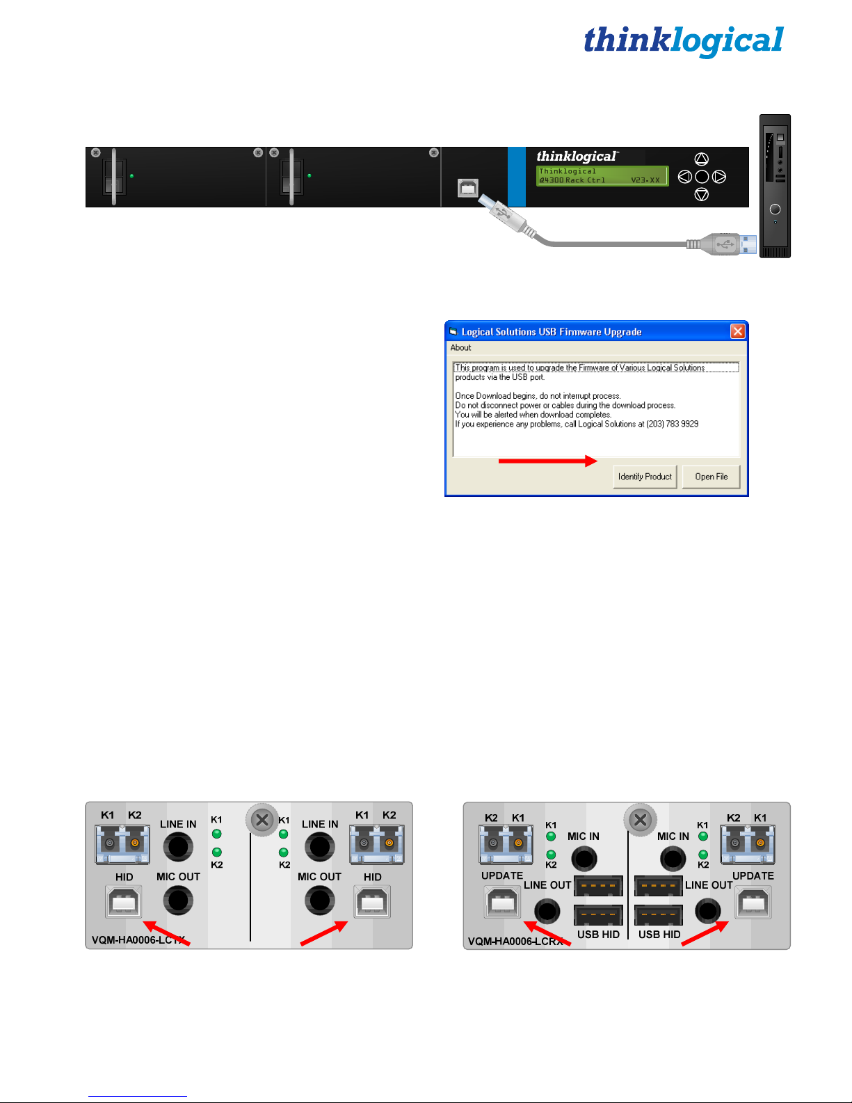
3.1.2. Program the Q-4300 Chassis
Q-4300 Front Panel
CPU
3.1.2.1.
chassis.
3.1.2.2.
POWER
UPDATE
USB-B
Q-4300
Quad Module Rack Mount Ch assis
Install a USB cable from the CPU’s USB-A port to the USB-B UPDATE Port on the front of the
Open the KM_Download application.
enterPOWER
USB-A
Select “Identify Product” and you will see the
name of the connected device.
NOTE: If you see “Logical Device not found,”
wait 5 seconds for the device to initialize and try
“Identify Product” again.
3.1.2.3.
on ‘open’ to initiate the file transfer. A progress bar indicates the file is being sent. DO NOT remove
the USB cable or power down the unit until the upgrade is complete.
Select “Open File.” Navigate to the proper directory for the product being updated and click
3.1.2.4.
When the download is complete, reset power to the chassis.
Also see the Q-4300 Chassis Firmware Upgrade Procedure in Appendix A on Page 28.
3.2. HID Microprocessor Programming
Each Q-Series KMASS Transmitter Module with USB HID has an HID PORT that serves as both an
HID Microprocessor Programming port and as a USB HID source. Each Q-Series KMASS Receiver
Module with USB HID has an UPDATE PORT that serves as an HID Microprocessor Programming
port.
A transmitter’s update port is a DEVICE port. A receiver’s update port is a HOST port.
DEVICE HOST
Q-Series KMASS Modules Product Manual
17
March 2013
Page 18

When updating the transmitter device port, the USB cable must be removed from the HID port
while the chassis power is off in order to reboot the module.
Repeat the steps in paragraph 3.1.2 for each of the update ports on the Q-Series KMASS Modules.
3.3. FPGA Downloads
Upgrades are available through Thinklogical. For technical assistance, please call us at:
1-203-647-8700.
To update a Module’s FPGA functionality, Install a USB cable from the CPU’s USB-A port to the USB-B
UPDATE Port on the front of the chassis (see diagram on page 17). Module FPGA functionality is
updated from the front panel and not from the connectors on the module.
The chassis is responsible for FPGA updates. Do not connect to the modules to update the FPGA.
3.3.1. FPGA Download Procedure:
Firmware files and revision numbers are stored in the following:
http://ftp.thinklogical.com/ftp/visualization/updates/
Then select FPGA_firmware.zip
The FPGA_Download.exe application & instructions are stored in:
http://ftp.thinklogical.com/ftp/visualization/updates/FPGA_upgrade.zip
3.3.2. FPGA Update Preparation:
1. Retrieve the Firmware files/revision numbers and the FPGA_Download application
/instructions and place them in an accessible directory in your CPU.
2. Copy the file FPGA_firmware.zip to a local directory and extract to a desired location.
3. Copy the file FPGA_upgrade.zip to a local directory.
4. Open the FPGA_upgrade.zip file and install the application files sent to the card stored in
FPGA_firmware.zip.
3.3.3. FPGA Update Procedure:
Complete steps 1-17 to update the FPGA:
STEP 1: If running Windows XP, the
Found New Hardware Wizard may open if
the Thinklogical product is being connected
to the PC for the first time. If the Wizard
does not open, proceed to Step 5
Q-Series KMASS Modules Product Manual
18
March 2013
Page 19
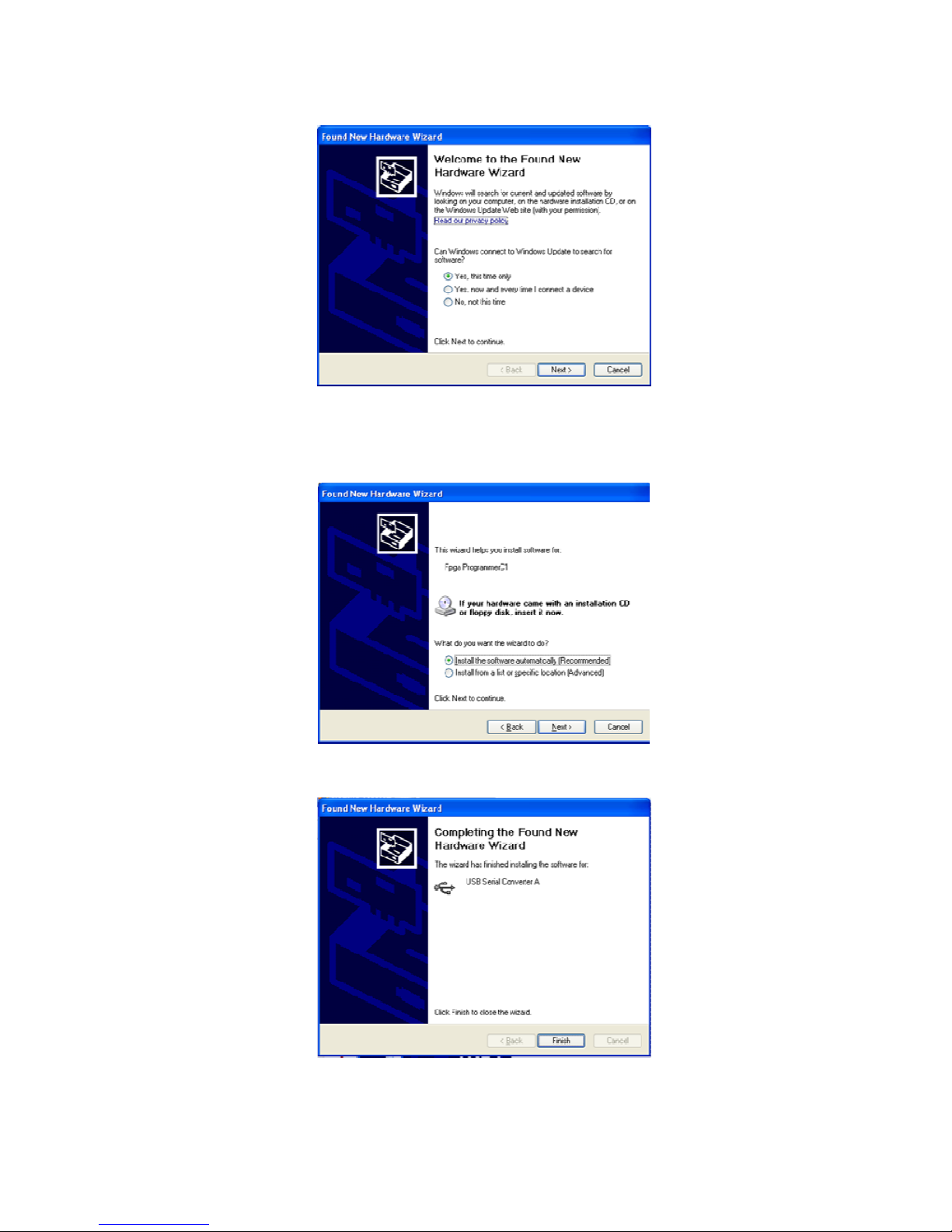
STEP 2: If not connected to the Internet, select No and navigate to where the FPGA Update
application is installed. The driver is in the Install Directory. Proceed to step 6. If using an
internet connection, select: Yes, this time only. Click on Next.
STEP 3: Select Install the software automatically (Recommended). Click on Next
STEP 4: Follow the instructions to the Completing the Found New Hardware Wizard Box.
Click on Finish.
Page 20
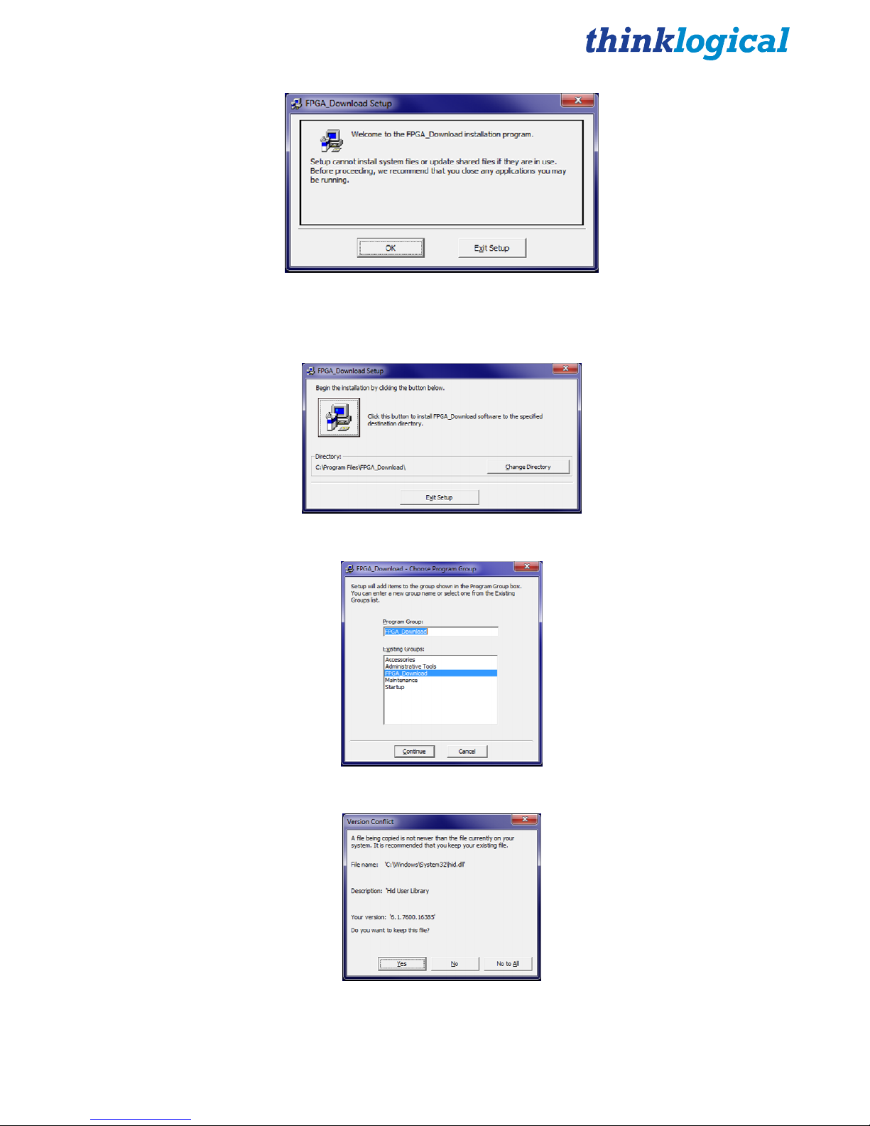
STEP 5:
To install the application,
double click on setup.exe (Contained in
FPGA_upgrade.zip). If asked for permission to make changes, select Yes. At the Welcome
screen, select OK.
STEP 6: Begin installation by clicking the displayed button.
STEP 7: Choose program group: Select Continue when the default selections are displayed.
STEP 8: The files will attempt to download. If a Version Conflict is displayed, select No to all.
Q-Series KMASS Modules Product Manual
20
March 2013
Page 21
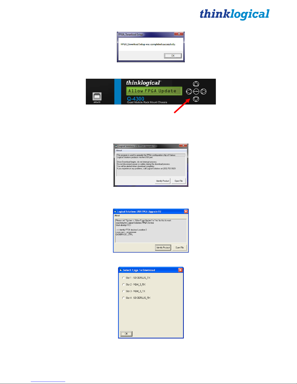
STEP 9: The FPGA download installation will now occur. When completed, press OK.
STEP 10: Connect the Device to the CPU:
A. Using the front panel Down button go to *System.
B. Scroll right ► until Allow FPGA Update is displayed, then press enter.
C. Use the down arrow to select Yes and press enter.
STEP 11: To Run the Application click on the CPU’s START button, then select FPGA
Download. Select Identify Product.
STEP 12: Once the product name is displayed, similar to above, select Open File.
STEP 13: Select the slot that describes the unit being updated and press OK.
Q-Series KMASS Modules Product Manual
21
March 2013
Page 22
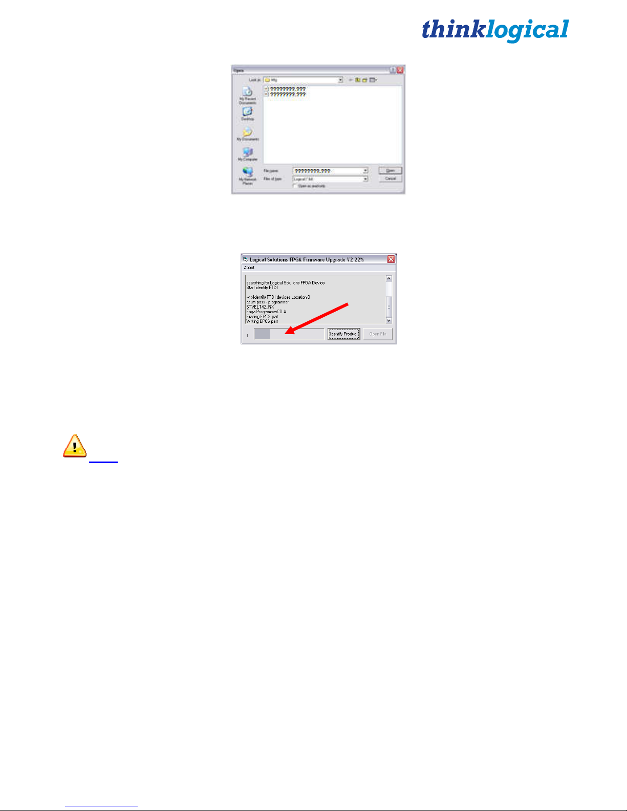
STEP 14: Press Open. Select the file to be loaded. (The file name will be displayed in the
small box near the bottom of the window, but may need to be specified under some
circumstances.)
STEP 15: The upgrade window will display the loading progress.
STEP 16: When completed, reboot the unit. On the front panel LCD, scroll down until you
come to *Card? where “?” indicates the number of the module to be verified. Scroll right ►
until the Rev is shown. Note this version. Scroll right to Sw Rev and verify that the latest
version is now displayed.
Note: It is good practice to verify that all the ports have been properly updated.
STEP 17: Repeat Steps 12-16 for all units to be updated.
Please contact Thinklogical® with any questions or comments at 1-203-647-8700 or
email us at support@thinklogical.com.
4. Regulatory & Safety Compliance
4.1 Safety Requirements
Symbols found on the product
Markings and labels on our products follow industry-standard conventions. Regulatory markings found
on our products comply with domestic and many international requirements.
Q-Series KMASS Modules Product Manual
22
March 2013
Page 23
Regulatory Compliance
Thinklogical’s® Q-Series products are designed and made in the U.S.A. Q-Series products have been
tested by a certified testing laboratory and found to be compliant with the following standards (both
domestic USA and many international locations):
North America
Safety
ANSI/UL60950-1: 1st Edition (2003)
CAN/CSA C22.2 No. 60950-1-03
Electromagnetic Interference
FCC CFR47, Part 15, Class A
Industry Canada ICES-003 Issue 2, Revision 1
LASER Safety
CDRH 21CFR 1040.10
Class 1 LASER Product
All Q-Series modules are designed and identified as
Class 1 LASER products
.
Australia & New Zealand
This is a Class A product. In a domestic environment this product may cause radio interference, in
which case the user may be required to take adequate measures.
European Union
Declaration of Conformity
Manufacturer’s Name & Address: Thinklogical, LLC®
100 Washington Street
Milford, Connecticut 06460 USA
Telephone 1-203-647-8700
These products comply with the requirements of the Low Voltage Directive 72/23/EEC and the EMC
Directive 89/336/EEC.
Standards with Which Our Products Comply
Safety
CENELEC EN 60950-1, 1st Edition (2001)
LASER Safety
IEC60825:2001 Parts 1 and 2
Class 1 LASER Product
Q-Series KMASS Modules Product Manual
23
March 2013
Page 24

Electromagnetic Emissions
EN55022: 1994 (IEC/CSPIR22: 1993)
EN61000-3-2/A14: 2000
EN61000-3-3: 1994
Electromagnetic Immunity
EN55024: 1998 Information Technology Equipment-Immunity Characteristics
EN61000-4-2: 1995 Electro-Static Discharge Test
EN61000-4-3: 1996 Radiated Immunity Field Test
EN61000-4-4: 1995 Electrical Fast Transient Test
EN61000-4-5: 1995 Power Supply Surge Test
EN61000-4-6: 1996 Conducted Immunity Test
EN61000-4-8: 1993 Magnetic Field Test
EN61000-4-11: 1994 Voltage Dips & Interrupts Test
4.2 Supplementary Information
The following statements may be appropriate for certain geographical regions and might not apply to
your location.
This Class A digital apparatus meets all requirements of the Canadian Interference-Causing Equipment
Regulations.
Cet appareil numérique de la classe A respecte toutes les exigencies du Règlement sur le matérial
brouilleur du Canada.
Warning! This is a Class A product. In a domestic environment, this product may
cause radio interference, in which case the user may be required to take corrective
measures.
Note: This equipment has been tested and found to comply with the limits for a
Class A digital device, pursuant to part 15 of the FCC Rules. These limits are
designed to provide reasonable protection against harmful interference when the
equipment is operated in a commercial environment. This equipment generates,
uses and can radiate radio frequency energy and, if not installed and used in
accordance with the instruction manual, may cause harmful interference to radio
communications in which case the user may be required to take adequate
corrective measures at their own expense.
Note: This Class A digital apparatus complies with Canadian ICES-003 and has
been verified as being compliant within the Class A limits of the FCC Radio
Frequency Device Rules (FCC Title 47, Part 15, Subpart B CLASS A), measured to
CISPR 22: 1993 limits and methods of measurement of Radio Disturbance
Characteristics of Information Technology Equipment.
Q-Series KMASS Modules Product Manual
24
March 2013
Page 25

Note:
electromagnetic fields
Note:
cable may be needed to comply with Immunity Requirements
The user may notice degraded audio performance in the presence of
.
If using a keyboard that is noise susceptible, a ferrite ring on the keyboard
Product Serial Number
Q-Series products have a unique serial number, imprinted on an adhesive label that is affixed to the
inside of the unit, face up. The serial number includes a date-code. The format for the date-code is 2
digits for the month, 2 digits for the day and 2 digits for the year, plus two or three digits for a unique
unit number. This serial number is also found on the original shipping carton.
Connection to the Product
Connections and installation hardware for our products use industry-standard devices and methods.
All wiring connections to the customer equipment are designed to minimize proprietary or customized
connectors and cabling. Power connections are made with regionally appropriate power cords and
approved methods.
5. How to Contact Us
5.1 Customer Support
Thinklogical® is an engineering company and you will receive any assistance you need directly from
our most knowledgeable engineers. We believe that the first lines of support are the design engineers
that developed each particular product. Therefore, your questions will be handled promptly by our inhouse engineers who are most familiar with your products.
Website
Check out our website for current product offerings, support information and general information about
all of the products we offer.
Our internet website offers product information on all current systems, including technical specification
sheets and installation guides (for viewing online or for download), product diagrams showing physical
connections and other information you might need.
Internet: www.thinklogical.com
Q-Series KMASS Modules Product Manual
25
March 2013
Page 26

Note: Most online documents are stored as Adobe Acrobat “PDF” files. If you do not have
the Adobe Acrobat reader needed to view PDF files, visit www.adobe.com for a download.
Email
Thinklogical® is staffed Monday through Friday from 8:30am to 5:00pm, Eastern Time Zone. We
will do our best to respond to your email inquiries promptly. Please use any of the following email
addresses for your specific needs:
info@thinklogical.com – Information on Thinklogical® and our products.
sales@thinklogical.com – Sales Department - orders, questions or issues.
support@thinklogical.com – Product support, technical issues or questions, product
repairs and request for Return Authorization.
Telephone
Telephone Sales: Contact our expert sales staff in Milford, CT at 1-203-647-8700 or if in the
continental US, you may use our toll-free number 1-800-291-3211. We are here Monday through
Friday from 8:30am to 5:00pm, Eastern Time Zone. Ask for your representative’s direct dial phone
number when you call.
Telephone Product Support: Contact Product Support by phone in Milford, CT at 1-203-647-8700.
The support lines are manned Monday through Friday, 8:30am to 5:00pm, Eastern Time Zone.
International Sales: Please contact our US sales staff in Milford, CT at 1-203-647-8700. We are here
Monday through Friday, 8:30am to 5:00pm, Eastern Time Zone (same as New York City). If leaving a
voice message please let us know the best time to call you back so we may reach you at your
convenience.
Our switchboard attendant will direct your call during regular business hours. We have an automated
attendant answering our main telephone switchboard after regular business hours and holidays. You
can leave voice messages for individuals at any time. Our Sales Representatives have direct numbers
to speed up your next call to us.
Fax
Our company facsimile number is 1-203-783-9949. Please indicate the nature of the fax on your cover
sheet and provide return contact information.
5.2 Product Support
Thinklogical’s® support personnel are available Monday through Friday from 8:30am to 5:00pm,
Eastern Time Zone. If your application requires assistance at some time outside of our normal
business hours, please contact us beforehand and we will do our best to make arrangements to help
you with your Thinklogical™ products.
5.2.1 Warranty
Thinklogical® warrants this product against defects in materials and workmanship for a period of one
year from the date of delivery. Thinklogical
Q-Series KMASS Modules Product Manual
®
and its suppliers disclaim any and all other warranties.
26
March 2013
Page 27

Note: Thinklogical® Inc. products carry a one year warranty, with longer term available at
time of purchase on most products. Please refer to your product invoice for your products
Warranty Terms & Conditions.
Defect remedy shall be the repair or replacement of the product, provided that the defective product is
returned to the authorized dealer within a year from the date of delivery.
If you wish to return your device, contact the Thinklogical® authorized dealer where you purchased the
device, or if you purchased directly, call Thinklogical® at 1-800-291-3211 (USA).
5.2.2 Return Authorization
In the event you must return a product to Thinklogical® directly, please contact Customer Support at
1-800-291-3211 or 1-203-647-8700. Customer Support will ask you to describe the problem and will
issue you a Return Merchandise Authorization number (RMA#). Pack the device in its original box, if
possible, and return it with the RMA# printed on the outside of the box.
Note: DO NOT return a product to Thinklogical® without a Return Material Authorization.
Return address for products with Return Material Authorization:
Attn: RMA#
100 Washington Street
Milford, CT 06460 USA
PH: 1-800-291-3211 (USA only)
Our Address
If you have any issue with a product, have product questions or need technical assistance with your
Thinklogical® system, please call us at 1-800-291-3211 (USA only) or 1-203-647-8700 and let us help.
If you’d like to write us, our mailing address is:
Thinklogical, LLC®.
100 Washington Street
Milford, CT 06460 USA
Q-Series KMASS Modules Product Manual
27
March 2013
Page 28

Appendix A- Q-4300 Chassis Firmware Upgrade Procedure
USB-A
USB-B
Q-Series KMASS Modules Product Manual
28
March 2013
Page 29

Q-Series KMASS Modules Product Manual
29
March 2013
Appendix B- Q-Series KMASS Module Quick Start Guide
Source CPU 1
Network Hub
STEP 7: Connect the MX48
Controller Card’s LAN Port to your
Controller CPU with a CAT5 cable.
(CPU IP address: 192.168.13.9)
Controller Card
IP Address: 192.168.13.15
QUICK-START GUIDE
QUICK-START GUIDE
STEP 1: C onnect the Q-Series KMASS Receiver Modules to a router u sing
multi-mode fiber-optic cables (up to 1 000 meters). Connect fiber K1 to any
SFP’sTransmit Port and fiber K2 to the same SFP’s Receive Port. Connect fi ber
K1' to any other SFP’s Tr ansmit Port and fiber K2' to the same SFP’s Receive
Port.
STEP 2: Ensure the Q-4300 Chassis Power Supply switches on the front panel
are in the OFF position. Install the Right Power Supply Module AC Power Cord
(Left receptacle) and the Left Power Sup ply Modu le AC Power Cord (Right
receptacle) onto the Q-4300 Chassis. Plug both AC Cords into a standard A C
source. On the front of the chassis, turn ON the Right and Left Power Supply
Modules.
STEP 3: Connect the USB and A udio peripheral devices to the Receive r
Modules using standard copper cab les as shown in the examples below. Turn all
the devices ON.
STEP 4: Connect the Q-Series KM ASS Transmitter Modules
to a router using multi-mode fiber-optic cables (up to 1000
meters). Connect fiber K1 to any SF P’s Receive Port and fiber
K2 to the same SF P’s Transmit Port. Connect fiber K1' to any
other SFP’s Receive Port and fiber K2' to the same SF P’s
Transmit Port.
STEP 5: Ensure the Q-4300 Chassis Power Supply switches on the
front panel are in the OFF position. Install the Right Power Supply
Module AC Power Cord (Left recep tacle) and the Left Power Supply
Module AC Power Cord (Right receptacle) into the Q-4300 Chassis.
Plug both AC Cords into a standard AC source. On the front of the
chassis, turn ON the Right and Left Pow er Supply Modules.
STEP 6: Con nect the USB and Audi o device sources from the CPU to
the Transmitters with standard copper cables. Ensur e the CPUs are
turned ON.
External Control CPU
2
5
7
MX48 Router KVM Matrix
Switch Chassis,
MXR-000048
3 Rack Units, 200 Watts
Q-Series Chassis
VQS-004300
VQM USB 2.0 Receiver
VQM-U00001-LCRX
VQM USB 2.0/USB HID/
Audio Receiver
VQM-UAP001-LCRX
VQM Redundant
USB HID/Audio Receiver
VQM-HAR001-LCRX
VQM Dual USB HID/Audio
Receiver
VQM-HA0006-LCRX
3
4
1
8
Transmitter Side
Receiver Side
Power Supply
As used with Thinklogical’s® Q-Series KMASS Modules Fiber Extension System
As used with Thinklogical’s® Q-Series KMASS Modules Fiber Extension System
STEP 8: Ensure the ON/OFF switch located above the Power
Supply’s AC receptacle is in the O FF position. Connect the
supplied AC Power Cord (PWR-000006-R) to the receptacle and
plug it into a standard AC s ource. Turn the switch ON. Verify that
all system functions are operating pro perly.
K1'
K2'
K2
K1
K2
Complete Steps 1-8 to connect to a KVM Matrix Router:
6
K1
K2'
K1'
K2 K1K2 K1K2 K1K1 K2 K1 K2 K1 K2
K1
K2
K1 K2
Source CPU 2
Source CPU 3
Source CPU 4
USB 2.0
USB HID*
USB 2.0
PS2 Kybd.*
PS2 Mouse*
Line IN
Line OUT
Line IN
Line OUT
Line IN 1
Line OUT 1
Line IN 2
Line OUT 2
USB HID
USB HID 1
USB HID 2
*Connect either USB HID or
PS2. If both are connected,
HID will over-ride PS2.
1
2 3 4
Q-Series Chassis
VQS-004300
VQM USB 2.0 Transmitter
VQM-U00001-LCTX
VQM USB 2.0/USB HID/
Audio Transmitter
VQM-UAP001-LCTX
VQM Redundant
USB HID/Audio Transmitter
VQM-HAR001-LCTX
VQM Dual USB HID/Audio
Transmitter
VQM-HA0006-LCTX
USB 2.0
USB HID
USB 2.0
USB HID
USB HID 1 USB HID 2
K1: Data TX to RX
K2: Data RX to TX
K1': Redundant Data TX to RX
K2': Redundant Data RX to TX
Local Audio
OUT CPU 2
Local Audio
OUT CPU 3
Local Audio
OUT CPU 4
 Loading...