

Page 1
OriginKVM 8250
Product Manual
Thinklogical™ Inc.
100 Washington Street
Milford, Connecticut 06460 U.S.A.
Telephone: 1-203-647-8700
Fax: 1-203-783-9949
www.thinklogical.com
High Performance KVM Switch
Revision C, February 2010
Page 2

Page 3

The Future of Access and Control
The Future of Access and Control
Copyright Notice
Copyright © 2010. All rights reserved. Printed in the U.S.A.
Thinklogical, a subsidiary of Logical Solutions, Incorporated™
100 Washington Street
Milford, Connecticut 06460 U.S.A.
Telephone 1-203-647-8700
All trademarks and service marks are property of their respective owners.
Subject: OriginKVM 8250, 8x2 KVM Switch
Revision: C, February 2010
February 2010 i REVISION C
Page 4

The Future of Access and Control
Table of Contents
1. Introduction ...................................................................................................................................... 1
1.1. Contents ................................................................................................................................... 1
1.2. Product Overview ..................................................................................................................... 1
2. System Features .............................................................................................................................. 2
2.1. General System Features ......................................................................................................... 2
2.2. Technical Specifications ........................................................................................................... 3
2.3. Product Overview ..................................................................................................................... 4
2.3.1. Mounting the OriginKVM 8250 .......................................................................................... 4
2.3.1.1. Rack Mount or Desktop ............................................................................................. 4
2.3.2. Front Panel Display and Buttons ....................................................................................... 4
2.3.3. Convection Cooled ........................................................................................................... 4
3. Connecting the OriginKVM 8250 ...................................................................................................... 5
3.1 The Front Panel ........................................................................................................................ 5
3.1.1 The Front Panel menu ...................................................................................................... 5
3.1.2 Out of Band Control .......................................................................................................... 8
3.2 The Rear Panel ........................................................................................................................ 9
3.3 Cable Kit KIT-000063-R ............................................................................................................ 9
4. Installation ...................................................................................................................................... 10
5. Regulatory and Safety Compliance ................................................................................................ 10
5.1 Safety Requirements .............................................................................................................. 10
5.1.1 Symbols Found on Product ............................................................................................. 10
5.2 Regulatory Compliance .......................................................................................................... 10
5.2.1 North America ................................................................................................................. 10
5.2.2 Australia & New Zealand ................................................................................................ 10
5.2.3 European Union .............................................................................................................. 11
5.2.3.1 Declaration of Conformity ............................................................................................ 11
5.2.3.2 Standards with which the Products Comply ................................................................ 11
5.2.4 Supplementary Information ............................................................................................. 12
5.2.5 Product Serial Number .................................................................................................... 12
6. How to Contact Us ......................................................................................................................... 13
6.1 Customer Support .................................................................................................................. 13
6.1.1 Website ........................................................................................................................... 13
6.1.2 Email .............................................................................................................................. 13
6.1.3 Telephone ....................................................................................................................... 14
6.1.4 Fax ................................................................................................................................. 14
6.2 Product Support...................................................................................................................... 14
6.2.1 Warranty ......................................................................................................................... 14
6.2.2 Our Address ................................................................................................................... 15
Appendix A: OriginKVM 8250 Quick Start Guide…………………………………….………..….……….…..16
Appendix B: *Out of Band Control for Apple Keyboard Users……………………….…….………..……….17
February 2010 ii REVISION C
Page 5
The Future of Access and Control
1. Introduction
HOST 2
100-240 V ~,0.5A, 50/60 Hz T2A, 250VAC
HDMI 1
HOST 1CONTROL
PS/2 1
CAUTION!
Replace withsame type and rating fuse.
PS/2 2
HDMI 2 HDMI 3 HDMI 4 HDMI 5 HDMI 6 HDMI 7 HDMI 8
1
2
3 4
5 6
7 8
DISPLAY 1
DISPLAY 2
1 2
USB 2.0
CONTROL
OUT
IN
1.1. Contents
When you receive your Thinklogical OriginKVM 8250™, you should find the following items:
OriginKVM 8250 Switch – KVM-008250
AC Power Cord – PWR-000006-R (International connections may differ)
OriginKVM 8250 Cable Kit – KIT-000063-R
OriginKVM 8250 Product Manual CD
1.2. Product Overview
Thinklogical’s OriginKVM 8250™ is a high performance KVM switch that enables true, simultaneous
multi-user access from two user stations. The design allows users to access and switch between eight
multi-platform servers. The OriginKVM 8250 improves operational productivity from the simplest to the
most complex requirements and for a variety of applications such as hardware/software development
and testing labs, network server manag ement and multi-workstation operation.
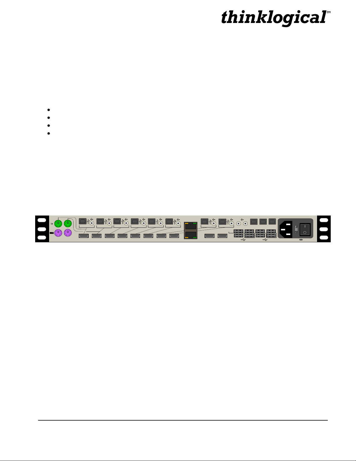
FIGURE 1: Rear View of OriginKVM 8250.
PART NUMBER DESCRIPTION
KVM-008250 OriginKVM 8250 Switch, DVI USB 8 IN x 2 OUT
February 2010 1 REVISION C
Page 6

The Future of Access and Control
2. System Features
2.1. General System Features
The Thinklogical OriginKVM 8250™ is a 2 user, 8 CPU switch. CPU connection ports 1 and 2 provide
either PS2 or USB interface to the PC. Ports 3 through 8 provide USB connections to the PC.
The OriginKVM 8250 is built with Thinklogical’s unique communication actuation technology which
allows for Out Of Band Control. This feature gives users the ability to select ports, configure servers in
the rack, assign names to servers and easily select and monitor them via on-screen menus. In addition,
the OriginKVM 8250 supports USB 1.0 HID device emulation and PS2/USB conversion. This feature
dedicates an individual device emulator to each connected computer, allowing the computer to have a
continuous connection to the keyboard and mouse even when the CPU is not selected. This ensures
flawless boot up of computers running a variety of operating systems. In addition, video intensive
applications now benefit with OriginKVM 8250’s DVI support. This feature maintains superior high
resolution video quality over short or long cable lengths.
Each OriginKVM 8250 system includes the following features:
Multi-user, simultaneous (2) user stations with access to 8 PCs
CPU Ports 1 and 2 have the option of USB Keyboard and Mouse or PS/2 Keyboard
and Mouse.
KVM switch with DVI performance video support
Easily configure, select and manage your system and servers via Thinklogical’s™
unique communication actuation technology and BIOS level access.
DDC pass through for HDMI support
USB pass through for support of USB 2.0 devices of any kind
User collaboration in order for 2 users to work on the same CPU at the same time
(HDMI and USB pass through for one user only while collaborating).
Scalable for multiple applications such as dual display, triple display, or quad display.
Units are stand alone and rack mountable (brackets included).
February 2010 2 REVISION C
Page 7

The Future of Access and Control
2.2. Technical Specifications
OriginKVM 8250
Storage Temperature
-20 to 70°C (-4 to 158°F), 10 to 90% RH, non-condensing
Power Supply Voltage
100 to 240 VAC, 50/60 Hz
Power Consumption
26 Watts, typical
Heat Dissipation
89 BTUs per hour
Panel Connectors
(2) Dual PS2 Keyboard and Mouse Connectors
(8) USB (B) Connectors
(8) HDMI Connectors
(3) USB (B) Connectors for Updates
(2) HDMI Connectors for Displays
(8) USB (A) Connectors - HID Keyboard and Mouse for Users- (3) HID,
(1) USB2.0 per User
(1) Power Input with On/Off Switch
(8) 3.5mm Audio Input Jacks
(2) 3.5mm Audio Output Jacks for Users
Refer to Section 3.3 for a view of the Rear Panel.
Front Panel Display
2 x 24 Liquid Crystal Display
Operating Temperature
and Humidity
0 to 50 °C (32 to 122 °F); 5 to 95% RH, non-condensing
Enclosure Dimensions
Approx. 14.25 x 17.50in x 1.75in high
(36.2cm x 44.5cm x 4.4cm high)
Weight
11 lb (4.99 kg)
Shipping Weight
27 lbs (12.25 kg)
Copper Cables
KIT-000063-R (CABLE KIT) contains the following:
(8) Audio Cables, 3.5mm Male to Male, 6FT
Thinklogical Part Number: CBL-000016-006-FR
(4) PS/2 Male to PS/2 Male, 6FT
Thinklogical Part Number: CBL000006-006FR
(8) USB Type A to USB Type B Cable, 6 Feet
Thinklogical Part Number: CBL000015-006FR
(10) HDMI Male to DVI Male Cable, 2 Meters
Thinklogical Part Number: CBL000030-002MR
February 2010 3 REVISION C
Page 8

The Future of Access and Control
LCD Navigation Pad
LCD System Information
and Programming
2.3. Product Overview
2.3.1. Mounting the OriginKVM 8250
You may choose to rack mount your OriginKVM 8250 or place it on a shelf or desktop (feet included).
The front panel display should be visible and front panel buttons accessible. All connections are made
to the rear of the chassis.
2.3.1.1. Rack Mount or Desktop
The OriginKVM 8250 may be installed in an EIA-standard 19 inch rack (1U tall), or placed on a shelf or
desktop. For shelf use, attachable rubber feet are provided and the rack mounted brackets can be easily
removed. The OriginKVM 8250 chassis does not need to be opened or accessed. The sturdy metal
case allows units to be stacked as required.
NOTE: Be sure to leave adequate ventilation space on both sides of the units, especially if units
are being stacked. Each rack mount bracket is held on by 4 screws. The brackets may be
positioned so that the unit sits forward or is recessed in your rack. If the brackets are
removed or repositioned, it is not necessary to re-use the left-over rack mount screws.
2.3.2. Front Panel Display and Buttons
The front-panel LCD display should be visible and accessible for system setup. The front panel buttons
are used to configure special video settings and to review existing OriginKVM 8250 configurations.
FIGURE 2: OriginKVM 8250 Front Panel LCD Display
2.3.3. Convection Cooled
The OriginKVM 8250 does not require special cooling or ventilation other than what is normally provided
in the equipment rack. No fan means that it does not add to the ambient noise in your equipment room
and it is less prone to equipment failure. Be sure not to block the air vents on the sides of the unit, and
leave space on both sides. If mounted in an enclosed rack, it is recommended that the rack have an
adequate ventilation fan to provide airflow through the unit(s).
February 2010 4 REVISION C
Page 9

The Future of Access and Control
3. Connecting the OriginKVM 8250
All physical connections to the product use industry-standard connectors. All connections are found on
the rear of the unit.
3.1 The Front Panel
3.1.1 The Front Panel Menu
The Front Panel Menu is arranged as follows:
Display Modifiable Description
FIGURE 3: OriginKVM 8250 Front Panel
*Connections
User1 Source YES Display and selects the number of the CPU selected by user 1
User2 Source YES Display and selects the number of the CPU selected by user 2
Display Modifiable Description
*Out Of Band Cntrl
User 1 Resolution YES Resolution of user 1 in band control
User 1 Color YES Color of user 1 in band control
User 1 Alt. HOT Key YES Select for Apple Keyboard user 1
User 1 Scan Mode Delay YES # of seconds a CPU is displayed in scan mode for user 1
User 2 Resolution YES Resolution of user 2 in band control
User 2 Color YES Color of user 2 in band control
User 2 Alt. HOT Key YES Select for Apple Keyboard user 2
User 2 Scan Mode Delay YES # of seconds a CPU is displayed in scan mode for user 1
February 2010 5 REVISION C
Page 10

The Future of Access and Control
Display Modifiable Description
*USB-1 Country Code
USB-1 Country NO For CPU 1 the country code of the USB KB that the device reports
itself as being. This is the last USB KB country applied to the
remote host. Most hardware is not localized and thus this value will
be zero (0), which is displayed As “Not Supported.”
USB-1 Device Enum NO For CPU 1 a bit pattern that indicates which ports have been
enumerated at the device side. The bits are laid out as Bit0-KB,
Bit1=MS, Bit2=TBLT, Bit3=DWNLD, Bit4=Daughter Card_KB, Bit5=
Daughter_MS, Bit6=Daughter_TBLT.
Display Modifiable Description
*PS2-1 Devices
PS2-1 KB Scan Code NO For CPU 1 indicates a value of 1, 2 or 3 for the scan code that the
device is told to emulate. If 0, then the keyboard is not properly
connected to the CPU.
PS2-1 Mouse NO For CPU 1 indicates a value of 0, 3 or 4 for the mode that the
device is told to emulate. If 255, then the mouse is not properly
connected to the CPU.
Display Modifiable Description
*USB-2 Country Code
USB-2 Country NO For CPU 2 the country code of the USB KB that the device reports
itself as being. This is the last USB KB country applied to the
remote host. Most hardware is not localized and thus this value will
be zero (0), which is displayed As “Not Supported.”
USB-2 Device Enum NO For CPU 2 a bit pattern that indicates which ports have been
enumerated at the device side. The bits are laid out as Bit0-KB,
Bit1=MS, Bit2=TBLT, Bit3=DWNLD, Bit4=Daughter Card_KB, Bit5=
Daughter_MS, Bit6=Daughter_TBLT.
February 2010 6 REVISION C
Page 11

The Future of Access and Control
Display Modifiable Description
*PS2-2 Devices
PS2-2 KB Scan Code NO For CPU 2 indicates a value of 1, 2 or 3 for the scan code that the
device is told to emulate. If 0, then the keyboard is not properly
connected to the CPU.
PS2-2 Mouse NO For CPU 2 indicates a value of 0, 3 or 4 for the mode that the
device is told to emulate. If 255, then the mouse is not properly
connected to the CPU.
Display Modifiable Description
System
Cntrl. Rev. NO Revision of Orig in Mux Control Code
Host 1 Rev NO Host for user 1 revision
Host 2 Rev NO Host for user 2 revision
Device 1 Rev NO Revision of device connected t o CPU 1
Device 2 Rev NO Revision of device connected t o CPU 2
Device 3 Rev NO Revision of device connected t o CPU 3
Device 4 Rev NO Revision of device connected to CPU 4
Device 5 Rev NO Revision of device connected to CPU 5
Device 6 Rev NO Revision of device connected to CPU 6
Device 7 Rev NO Revision of device connected t o CPU 7
Device 8 Rev NO Revision of device connected to CPU 8
Debug Values YES Factory Debug facility
DDC
Acquire DDC fro m USER1 YES Loads USER1 monitor’s DDC Table into all CPU
Get Default DDC YES Loads Thinklogical default DDC Table
February 2010 7 REVISION C
Page 12

The Future of Access and Control
3.1.2 Out of Band Control
The Out Of Band Control is presented as follows:
The integrated *Out Of Band Control is accessed by users by pressing Scroll Lock twice within 2
seconds. (For Apple keyboard users, see Appendix B on page 17.) This feature gives users the ability
to select ports, configure servers in the rack, assign names to servers and easily select and monitor
them via on-screen menus. CPUs are selected by pressing the up or down arrow key or by pressing the
number of the CPU you wish to access. This will move the user number, (shown on the left) to the
desired CPU. Once the desired CPU is selected enter is pressed to confirm selection. If a CPU is being
used, the CPU can be viewed but the keyboard and mouse will be controlled by the first user to access
the CPU.
To take control of the keyboard and mouse, press the letter “t” just before pressing enter to select the
CPU.
CPUs may be named by pressing the right arrow key and typing in a name. Pressing enter will store the
name in non-volatile memory. The user interface will slowly shift positions diagonally down and to the
right in order to prevent burning a retentive image onto the screen.
*Out Of Band Control resolution is selected via the front panel of the 8250. Resolutions provided are
1024x768, 1280x1024 and 1600x1200. The color of the Out Of Band Control may also be selected from
the options of Green, Cyan, Red, Magenta and Yellow.
When the user selects Scan Mode, the Origin 8250 will first display the number of the CPU to be
presented, then video from the CPU. The port number and the CPU will each be shown for ½ the
number of seconds specified on the front panel “UserX Scan Mode Delay” menu. After the specified
number of “UserX Scan Mode Delay” seconds, the next CPU will be selected.
February 2010 8 REVISION C
Page 13

The Future of Access and Control
3.2 The Rear Panel
HOST 2
100-240 V ~, 0.5A, 50/ 60 Hz T 2A , 250VAC
HDMI 1
HOST 1CONTROL
PS/2 1
CAUTION!
Replace with same type and rating fuse.
PS/2 2
HDMI 2 HDMI 3 HDMI 4 HDMI 5 HDMI 6 HDMI 7 HDMI 8
1
2
3 4
5 6
7 8
DISPLAY 1
DISPLAY 2
1 2
USB 2.0
CONTROL
OUT
IN
PS2 Option
(Ports 1 and 2)
RJ45
Control OUT/IN
USB-B and
Audio IN (1-8)
HDMI IN
(1-8)
AC IN ON/OFF
Three USB 1.0/ One USB 2.0
(Users 1 & 2)
Audio OUT (1-2)
Firmware
Upgrade Ports
Display
OUT (1-2)
PS/2 to PS/2 Male, 6' (CBL-000006-006FR) – Qty 4
USB A-B, 6' (CBL-000015-006FR) – Qty 8
HDMI to DVI, 6' (CBL-000030-002FR) – Qty 10
3.5mm M/M Audio, 6' (CBL-000016-006FR) – Qty 8
3.3 Cable KIT-000063-R
February 2010 9 REVISION C
Page 14

The Future of Access and Control
4. Installation
Please refer to the Quick Start Guide included in Appendix A on page 16.
5. Regulatory and Safety Compliance
5.1 Safety Requirements
5.1.1 Symbols Found on Product
Markings and labels on the product follow industry-standard conventions. Regulatory markings found on
the products comply wit h domestic and many international requirements.
5.2 Regulatory Compliance
Thinklogical Inc. products are designed and made in the USA. Our products have been tested by a
nationally certified testing laboratory and found to be compliant with the following standards (both
domestic USA and many international locations).
5.2.1 North America
These products comply with the following standards:
Safety
ANSI/UL60950-1: 1st Edition (2003)
CAN/CSA C22.2 No. 60950-1-03
Electromagnetic Interference
FCC CFR47, Part 15, Class 1
Industry Canada ICES-003 Issue 2, Revision 1
5.2.2 Australia & New Zealand
This is a Class 1 product. In a domestic environment this product may cause radio interference, in which
case the user may be required to take corrective measures.
February 2010 10 REVISION C
Page 15

The Future of Access and Control
5.2.3 European Union
5.2.3.1 Declaration of Conformity
Manufacturers name and address:
Thinklogical, a subsidiary of Logical Solutions™, Inc.
100 Washington Street
Milford, CT 06460 USA
Telephone (203)647-8700
Product name
Model: OriginKVM 8250
This product complies with the requirements of the Low Voltage Directive 72/23/EEC and the EMC
Directive 89/336/EEC.
5.2.3.2 Stan dards with which the Products Comply
Safety
CENE L EC EN 6 0 9 50-1, 1st Edition (2001)
Electromagnetic Emissions
EN55022: 1994 (IEC/CSPIR22:1993)
EN61000-3-2/A14:2000
EN61000-3-3:1994
Electromagnetic Immunity
EN55024:1998 Information Technology Equipment-Immunity Characteristics
EN61000-4-2:1995 Electro-Static Discharge Test
EN61000-4-3:1996 Radiated Immunity Field Test
EN61000-4-4:1995 Electrical Fast Transient Test
EN61000-4-5:1995 Power Supply Surge Test
EN61000-4-6:1996 Conducted Immunity Test
EN61000-4-8:1993 Magnetic Field Test
EN61000-4-11:1994 Voltage Dips & I nterrupts Test
February 2010 11 REVISION C
Page 16

The Future of Access and Control
5.2.4 Supplementary Information
The following statements may be appropriate for certain geographical regions and might not apply to
your location.
NOTE: This equipment has been tested and found to comply with the limits for a Class 1 digital device,
pursuant to part 15 of the FCC Rules. These limits are designed to provide reasonable protection
against harmful interference when the equipment is operated in a commercial environment. This
equipment uses, generates and can radiate radio frequency energy and, if not installed and used
in accordance with the instruction manual, may cause harmful interference to radio
communications. Operation of this equipment in a residential area is likely to cause harmful
interference in which case the user may be required to correct the interference.
NOTE: This Class 1 digital apparatus complies with Canadian ICES-003 and has been verified as being
compliant within the Class 1 limits of the FCC Radio Frequency Device Rules (FCC Title 47, Part
15, Subpart B Class 1), measured to CISPR 22: 1993 limits and methods of measurement of
Radio Disturbance Characteristics of Information Technology Equipment.
This Class 1 digital apparatus meets all requirements of the Canadian Interference-Causing Equipment
Regulations.
Cet appareil numerique de la classe 1 respecte toutes les exigencies du Reglement sur le material
brouilleur du Canada.
WARNING: This is a Class 1 product. In a domestic environment this product may cause radio
interference, in which case the user may be required to take corrective measures.
NOTE: The user may notice degraded audio performance in the presence of electromagnetic fields.
5.2.5 Product Serial Number
Thinklogical products have a unique serial number, imprinted on a small silver label that is placed on the
bottom of the chassis. The serial number includes a date-code. The format for the date-code is two
digits for the month; two digits for the day and two digits for the year and two or three digits for a unique
unit number. This serial number is also found on the original shipping carton.
February 2010 12 REVISION C
Page 17

The Future of Access and Control
6. How to Contact Us
6.1 Customer Support
Thank you for choosing Thinklogical™ products for your application. We appreciate your business and
are dedicated to helping you use our products. Let Thinklogical help you with any issues you may have.
Thinklogical is an engineering company and we believe that the first line of support is the design
engineer that developed your product. Therefore, your questions will be handled promptly by our inhouse engineers that are most familiar with your products.
To contact Thinklogical, please use the following telephone numbers and internet-based methods.
6.1.1 Website
Check out our website for product information, current updates and the full line of Thinklogical products.
Our internet website offers product information on all current systems, including technical specification
sheets and installation guides (for viewing online or for download), Quick Start Guides showing physical
connections and other information you might need.
Internet: www.thinklogical.com
*NOTE: Most online documents are stored as Adobe Acrobat “PDF” files. If you do not have the Adobe
Acrobat reader needed to view PDF files, visit www.adobe.com for a download.
6.1.2 Email
Thinklogical is staffed Monday through Friday from 8:30am to 5:00pm, Eastern Time Zone. We will
respond to your email inquiries promptly. Please use either of the following email addresses:
info@thinklogical.com – Information about Thinklogical and our products.
sales@thinklogical.com – Sales Department - orders, questions or issues.
support@thinklogical.com – Product support, technical issues or questions, product
repairs and request for Return Authorization.
February 2010 13 REVISION C
Page 18

The Future of Access and Control
6.1.3 Telephone
Telephone Sales: Please contact our expert sales staff via telephone in Milford, CT at 1-203-647-8700
or if in the continental US, you may use our toll-free number 1-800-291-3211. We are here Monday
through Friday from 8:30am to 5:00pm, Eastern Time Zone. Ask for their direct dial phone number when
you call.
Telephone Product Support: Please contact Product Support via telephone in Milford, Connecticut at
1-203-647-8700. Our support lines are manned Monday through Friday, 8:30 am to 5:00pm, Eastern
Time Zone.
International Sales: Please contact our US sales staff in Milford, CT at 1-203-647-8700. We are here
Monday through Friday, 8:30am to 5:00pm, Eastern Time Zone (same as New York City). If leaving a
voice message, please suggest a “best time to call back” so we may reach you at your convenience.
Our switchboard attendant will direct your call during regular business hours. We have an automated
attendant answering our main telephone switchboard after regular business hours and on holidays. You
can leave voice messages for an individual at any time. Our Sales Representatives have direct numbers
to help facilitate your next call to us.
6.1.4 Fax
Our company facsimile number is 1-203-783-9949. Please indicate the nature of the fax on your cover
sheet and provide return contact information.
6.2 Product Support
Thinklogical’s support personnel are available Monday through Friday from 8:30am to 5:00pm, Eastern
Time Zone. If your application requires assistance at some time outside of our normal business hours,
please contact us beforehand and we will do our best to make arrangements to help you with your
Thinklogical products.
6.2.1 Limited Warranty Information
Thinklogical, LLC (“Thinklogical”) warrants this product against defects in materials and workmanship for
a period of one (1) year from the date of delivery (ordinary wear and tear excluded). This limited
warranty does not cover defects resulting from (i) use of the product other than as described in the
applicable documentation for the product; (ii) modifications to or repairs of the product that are made by
any party other than Thinklogical or a party acting on Thinklogical’s behalf, or (iii) combination of the
product with third party products that is not consented to by Thinklogical. Occurrences of events
described in (i) – (iii) shall void the foregoing warranty. This warranty gives you specific legal rights, and
you may also have other rights which vary from state to state.
Except for the express warranty set forth above, to the fullest extent permitted under applicable
law, Thinklogical, LLC and its suppliers disclaim any and all other warranties, express and
implied, including without limitation the implied warranties of merchantability, fitness for a
particular purpose, title and non-infringement.
February 2010 14 REVISION C
Page 19

The Future of Access and Control
If the defective product is returned to the authorized dealer within one (1) year of the delivery date, repair
or replacement of the product will be made. Repairs may be made with refurbished parts. If repair or
replacement is not possible, Thinklogical may keep the defective product and refund the amount that you
paid for the defective product. These are Thinklogical’s sole obligations, and your exclusive remedies,
for a breach of the limited warranty set forth above.
To return a defective product, contact the Thinklogical authorized dealer from whom you purchased the
product. Do not return a product directly to Thinklogical without prior authorization from your dealer.
If you have received prior authorization from your dealer and are returning a product directly to
Thinklogical:
1. Contact your sales representative, or call Customer Support at (800)291–3211 or + (203)647–
8700.
2. Describe the defect with the product and Customer Support will issue a Return Merchandise
Authorization Number (RMA#).
3. Pack the product in all of its original packing, if possible, and write the RMA number on the box.
4. Return the product to:
Thinklogical, LLC
Attn: RMA# [Insert the RMA# issued to you, by Thinklogical, here.]
100 Washington Street
Milford, CT 06460 USA
6.2.2 Our Address
If you have any product issues, have product questions or need technical assistance with your
Thinklogical system, please call us at 1-203-647-8700 and let us help.
If shipping something with an RMA # or if you’d like to write us, our location is:
Thinklogical™ Inc.
100 Washington Street
Milford, CT 06460 USA
February 2010 15 REVISION C
Page 20

The Future of Access and Control
DISPLAY 1
2
USB HID “B” Connector
(to the Host System)
HOST 2
100-240 V ~,0.5A, 50
/
60 Hz T2A, 250VAC
HDMI 1
HOST 1CONTROL
PS/2 1
CAUTION!
Replacewith same typeand rating fuse.
PS/2 2
HDMI 2 HDMI 3 HDMI 4 HDMI 5 HDMI 6 HDMI 7 HDMI 8
1
2
3 4
5 6
7 8
DISPLAY 1
DISPLAY 2
1 2
USB 2.0
CONTROL
OUT
IN
STEP 1
Check contents
When you receive your Thinklogical™ OriginKVM 8250, you should find the
following items:
OriginKVM 8250 Switch – KVM-008250
AC Power Cord – PWR-000006-R (Internationalconnections may differ)
OriginKVM 8250 Cable Kit – KIT-000063-R
OriginKVM 8250 Product Manual
DVI-DConnector1
PS/2 Option
DVI-DConnector2
USB Option
PS/2 Option (Ports 1 and 2 only)
1. CPU to DVI Port 1 or 2using CBL-000030-002MR.
2. CPU to PS/2 Keyboard and Mouse Port1 or 2 using (2)
CBL-000006-006FR.
3. CPU to Audio IN Port 1 or2 using CBL-00016-006FR.
USB Option (Ports 1 through 8)
1. CPU to any DVI Port 1-8 usingCBL-000030-002MR.
2. CPU to USB Keyboard and Mouse Port1-8 using (1)
CBL-000015-006FR.
3. CPU to Audio IN Port 1-8 usingCBL-00016-006FR.
1
1
2
2
3
3
USER 1
USER 2
OriginKVM 8250
USB HID “A” Connector
(from the USB Device)
PS/2 to PS/2 Male, 6 ft. (CBL-000006-006FR) –Qty 4
USB A-B, 6 ft. (CBL-000015-006FR) – Qty 8
HDMI to DVI, 6 ft. (CBL-000030-002FR) – Qty 10
3.5mm Male/Male Audio, 6 ft. (CBL-000016-006FR) – Qty 8
RJ45 Connector
RJ45 Connector
(Optional) OriginKVM 8250 Unit 2
3
4
STEP 2
Connect your CPU
to the desired DVI
Port using DVI
cable CBL-000030-
002MR.
STEP 3
If using the PS/2 option, connect
your CPU to the keyboard and
mouse at Ports 1 or 2 only using the
2 cables (CBL-000006-006FR)
provided.
STEP 4
Connect your CPU to Audio IN using cable CBL-000016-006FR.
Be sure each set of DVI, Keyboard/Mouse and Audio inputs are
connected to thesame numbered ports.
STEP 6
Ensure that the Power Switch is in the OFF (0)
position. Connect thesupplied AC Power Cord
(PWR-000006-R)
to the OriginKVM 8250 power
receptacle and turnthe unit ON (1).
Ensure that all system functions are operating
properly.
STEP 8 (Optional)
More than one OriginKVM 8250 unit can be cascaded together to handle multiple
single-link videos. Usinga standard CAT5 cable with RJ45 connectors (not
provided), connect to the CONTROL OUT receptacle on OriginKVM Unit 1 and the
other end to the CONTROL IN receptacle on OriginKVM Unit 2. Up to 8 units canbe
cascaded by repeatingthis process for each unit added.
8
If using the USB option, connect your CPU to the
keyboard and mouseat any desired Port 1
through 8 usingone USB cable (CBL-000015-
006FR) provided.
STEP 5
Connect all required HID devices as shown.
The OriginKVM 8250can support a full set of
HID devices fortwo user stations.
1
USB 2.0
USER 2: Three USB 1.0 and one USB 2.0 ports.
5
1
2
1
2
USER 1: Three USB 1.0 and one USB 2.0 ports.
NOTE: On some OriginKVM 8250 models, the
rectangular USB 2.0 designation symbols may
indicate the wrong ports. The USB 2.0 port is always
the lower right of the four user ports, located below
the midline between the two rows of USB ports, as
shown below and above.
High Performance KVM Switch
6
7
STEP 7
Turn the computers ON
and ensure that all system
functions are operating
properly
DVI
Display 1
DVI
Display 2
OriginKVM_8250_Quick_Start_Manual_Rev_A
QUICK START
GUIDE
V
A
/
A
V
A
/
A
/
A
A
HOST 2
100-240V~,0.5A,50
/
60Hz T
2A,250VAC
HDMI 1
HOST 1CONTROL
PS/2 1
CAUTION!
Replacewith same typeand ratingfuse.
PS/2 2
HDMI 2 HDMI 3 HDMI 4 HDMI 5 HDMI 6 HDMI 7 HDMI 8
1
2
3 4
5 6
7 8
DISPLAY 1
DISPLAY 2
1 2
USB 2.0
CONTROL
OUT
IN
1
2
Appendix A: Origin 8250 Quick Start Guide
February 2010 16 REVISION C
Page 21

The Future of Access and Control
Appendix B: Out of Band Control
LCD Navigation Pad
LCD System Information
and Programming
enter
User 1
Alt. HOT Key NOT USED
LEFT
CONTROL
RIGHT
CONTROL
F13 F14 F15
APPLE KEYBOARD
Alternate Key Strokes
For Apple Keyboard Users
If using an Apple Keyboard, once the firmware has been installed into the OriginKVM 8250, for User 1
use the UP arrow on the Navigation Pad to reach *Out of Band CTRL from the main menu. Then
use the RIGHT arrow to reach User 1 Alt. HOT Key NOT USED. If not using an Apple Keyboard,
leave this setting as it is.
To make a change from the Alt. HOT Key menu, press enter. Use the UP or DOWN arrow to
access the available alternate hot key options:
Press enter to implement the change. Each keyboard is handled separately. The user may need to
repeat the procedure for User 2.
Alt. HOT Key (F13, F14, F15, LEFT CTRL, RIGHT CTRL or R or L CTRL).
February 2010 17 REVISION C
 Loading...