

Page 1

ImageEvolution X3
Product Manual
Thinklogical LLC.
100 Washington Street
Milford, Connecticut 06460 U.S.A.
Telephone (203) 647-8700
Fax (203) 783-9949
www.thinklogical.com
Page 2

Copyright Notice
Copyright © 2011 All rights reserved. Printed in the U.S.A.
Thinklogical LLC
100 Washington Street
Milford, Connecticut 06460 U.S.A.
Telephone (203) 647-8700
All trademarks and service marks are property of their respective owners.
Subject: ImageEvolution X3
Revision: Rev D, June 2011
Revision D 2 June 2011
Page 3

Table of Contents
PREFACE
About this Product Manual
This product manual is divided into four sections for Introduction, System Features, Connecting
the Image Evolution X3, Installation, Regulatory and Safety Compliance and Product Support.
These are sub-divided to help you easily find the topics and procedures you are looking for.
This manual also contains Appendices.
Conventions Used in this Manual
As you read this manual you will notice certain conventions that bring your attention to important
information. These are Notes and Warnings. Examples are shown below.
Note: Important Notes appear in blue text preceded by a yellow exclamation
point symbol, like this.
A note is meant to call the reader’s attention to helpful information at a point in the text that is
relevant to the subject being discussed.
Warning! All Warnings appear in red text, followed by blue text, and pre-
ceded by a red stop sign, like this.
A warning is meant to call the reader’s attention to critical information at a point in the text that is
relevant to the subject being discussed.
Revision D 3 June 2011
Page 4
1. Introduction
1.1. Contents
When you receive your Thinklogical ImageEvolution X3, you should find the following items:
• ImageEvolution X3 Switch – IEC-000003.
• AC power cord – PWR-000006-R (International connections may differ).
• ImageEvolution X3 product manual.
1.2. Product Overview
The Thinklogical ImageEvolution X3 is a high performance scaler and frame rate converter unit
that allows for advanced image enhancement. The unit supports SD, HD/Dual-Link HD/3G SDI
and supports SMPTE standards.
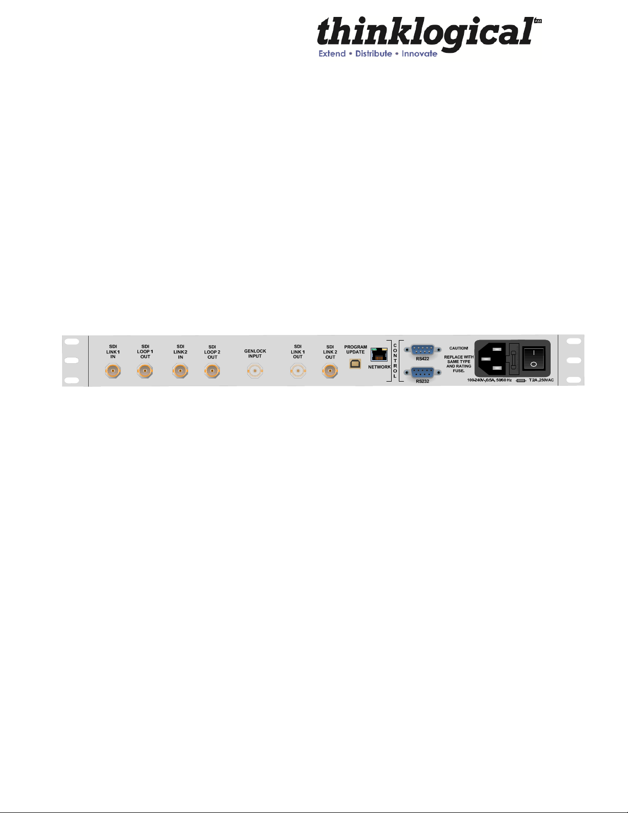
FIGURE 1: Rear View of ImageEvolution X3
The following model is available from Thinklogical:
IEC-000003 ImageEvolution X3
Revision D 4 June 2011
Page 5

2. System Features
2.1. General System Features
The ImageEvolution X3 is a high performance converter and scaler that transitions SDI video
signals into any desired output format and provides the highest quality images for professional
audio-visual end users
audio and ancillary data. Users are able to control the ImageEvolution X3 through its front
panel multi-function selector. RS-232 and RS-422 port are available for remote control of the
unit. An internal AC power supply means no wall wart so the product can easily be stand-alone
or rack mounted.
Each ImageEvolution X3 system includes the following features:
Conversion/Scaling:
• Input and Output: SD, HD-SDI, Dual-link HD-SDI, 3D, 3G*
• Input and output formats supported: progressive, interlaced, PsF
.
System features include support for up to 8 channels of embedded
• 3D Processing
• Conversion of dual stream HD-SDI input to side-by-side 3G-SDI or
HD-SDI Output
• Conversion of dual stream HD-SDI input to line interleaved 3G-SDI Output
• Conversion of dual stream HD-SDI input to dual stream HD-SDI Output
• Conversion of side-by-side 3G-SDI or HD-SDI to a 2D right half image
3G-SDI or HD-SDI Output
• Supports Closed Captioning and Time Code Processing
• SMPTE standards supported: 259M-C, 292, 372M, 424M, 425 level A and level B
• Active SMPTE compliant loop out ports
• Internal universal AC power supply
• Supports 8 channels of embedded audio, as well as ancillary data
• 20 user programmable presets
• Genlock Capable (House Sync)
note1: 12-bit max supported on output, 10-bit max supported on input
note2: YCbCr & RGB supported on output, YCbCr supported on input
Video Processor Features:
• Per pixel motion-adaptive video noise reduction- removes the white Gaussian noise
present in most types of video
Revision D 5 June 2011
Page 6

• Content adaptive block and mosquito noise reduction- significantly reduces the blocking
and mosquito noise artifacts present in compressed video
• Advanced per-pixel, motion-adaptive, edge-adaptive 3D de-interlacing with support for
arbitrary film cadences- removes “jaggies” and “feathering” to produce smooth and clear
images
• Adaptive scaling- produces sharp and clean images and low or high resolutions
• Natural depth expansion- enhances details and sensation of depth for greater realism
and super resolution effect
• Adaptive contrast enhancement (ACE) brings out shadow detail without crushing midtones or highlights
• Intelligent color remapping (ICR) enables vivid color without hue shifts and clipping while
maintaining accurate flesh tone
• Qdeo™ true color- a unique solution for using the full dynamic range of 10-bit and 12-bit
displays which eliminates contouring seen when viewing typical 8-bit consumer video
Revision D 6 June 2011
Page 7

Storage Temperature
Power Supply Voltage
Power Consumption
Heat Dissipation
Rear Panel Connectors
Operating Temperature and
Enclosure Dimensions
Compliance
Technical Specifications
Frame Rate Formats Supported: Progressive, Interlaced, PsF
Function Video Standards Supported Formats
SD-SDI SMPTE 259M PAL and NTSC
HD-SDI SMPTE 292M All standard HD-SDI compatible formats
Dual-link HD-SDI SMPTE 372M All 1080 line video formats compatible with
SMPTE 372M
3G SDI SMPTE 424M, 425M, Level A and B All SMPTE 425 level A and B compatible
formats
0 to 50 deg C , 5 – 95 % RH, non condensing
100 to 240 VAC, 50/60 Hz Universal AC power supply
26 Watts, typical
88.7 BTUs per hour
Humidity
USB B (1)
Console Port RS-422 M (1)
Console Port RS-232 F (1)
HD-SDI Input BNC Connectors with Loopback outputs (2)
HD-SDI BNC Connectors HD-SDI Out (2)
Genlock BNC Input (1)
RJ45 Connector for 10/100 base ’T’ Ethernet (1)
BNC Connector for GENLOCK input (1)
0 to 50 °C (32 to 122 °F); 5 to 95% RH, non-condens ing
Rack Size: EIA 19"
Height: 1U-1.72" (43.69mm)
Depth: 9.5 (241.3mm)
Width: 17.49" (444.2mm)
Pending approvals for US, Canada, and European Union
Revision D 7 June 2011
Page 8
2.2. Hardware
2.2.1. Desktop or Rack Mount Device
You may choose to place it on a shelf or desktop (rubber feet included), or rack mount using
the supplied mounting brackets (19 inch rack mountable). The front panel should be visible
and unobstructed to facilitate programming. The front panel buttons may also need to be
accessible. All connections are made to the rear of the chassis. The ImageEvolution X3
chassis does not need to be opened or accessed. The sturdy metal case allows units to be
stacked, as required.
2.2.2. Cooling
The ImageEvolution X3 uses two DC fans to move air horizontally through the enclosure.
They will turn on automatically when the internal temperature reaches a preprogrammed
temperature.
Note: Be sure to leave adequate ventilation space on both sides of the units
(2” minimum), especially if the units are being stacked.
3. Connecting the ImageEvolution X3
connections are found on the rear of the unit.
All physical connections to the product use industry-standard connectors. All
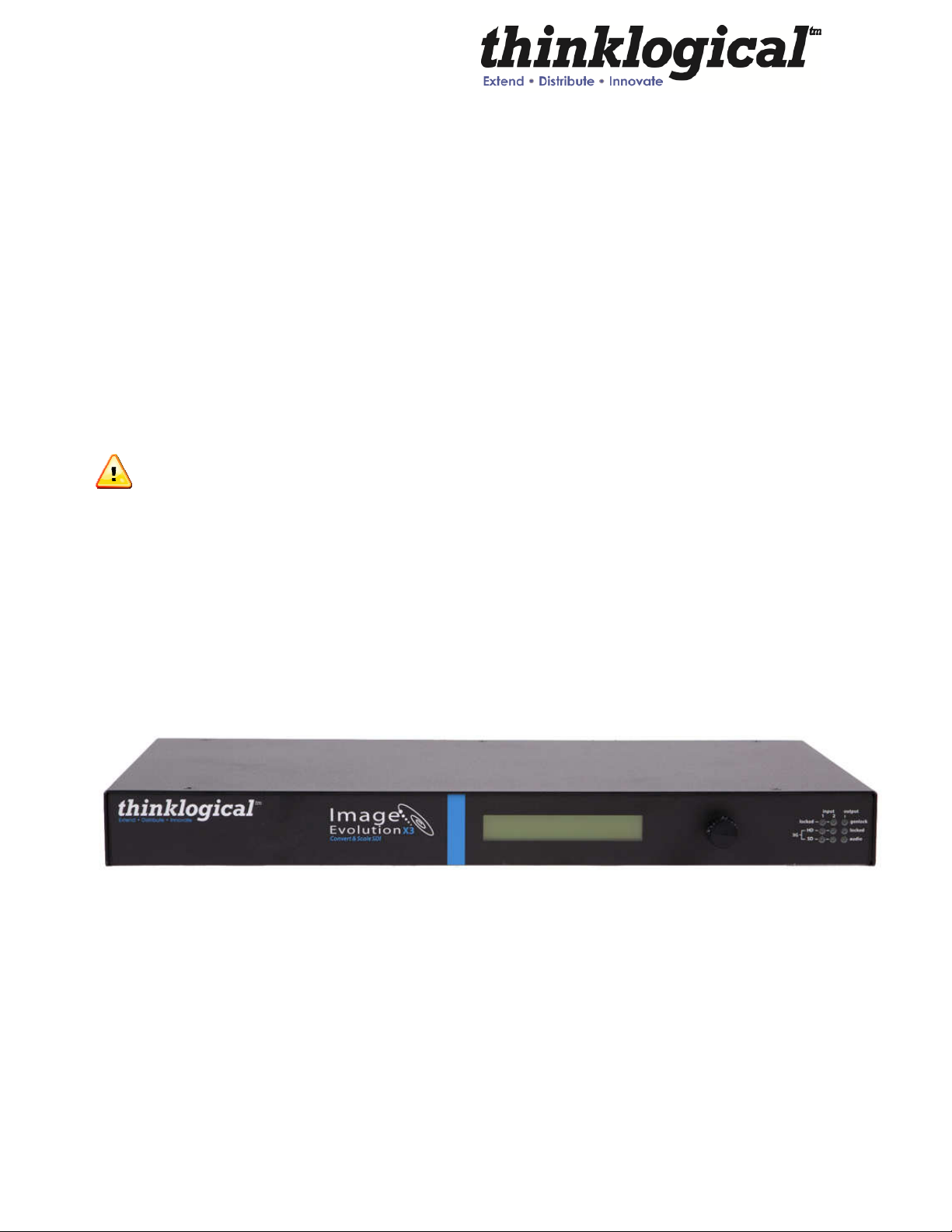
3.1 Front Panel View:
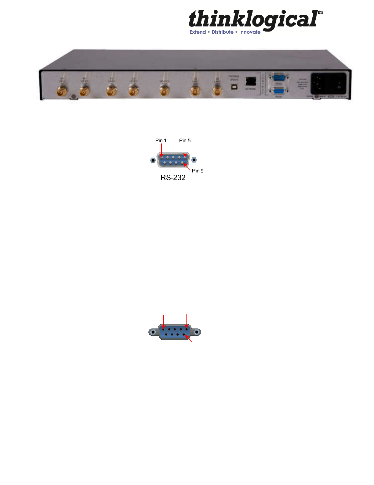
3.2 Rear Panel View
Revision D 8 June 2011
Page 9
3.3
3.4
RS-232 Pin Out
Pin 1 DCD_OUT
Pin 2 RX_ IN
Pin 3 TX_OUT
Pin 4 DTR_IN
Pin 5 GND
Pin 6 DSR_OUT
Pin 7 RTS_IN
Pin 8 CTS_OUT
Pin 9 RI_OUT
RS-422 Pin Out
Pin 1 Pin 5
Pin 9
RS-422
Pin 1 GND
Pin 2 RX +
Pin 3 TXPin 4 GND
Pin 5 NC
Pin 6 GND
Pin 7 RXPin 8 TX+
Pin 9 GND
Revision D 9 June 2011
Page 10
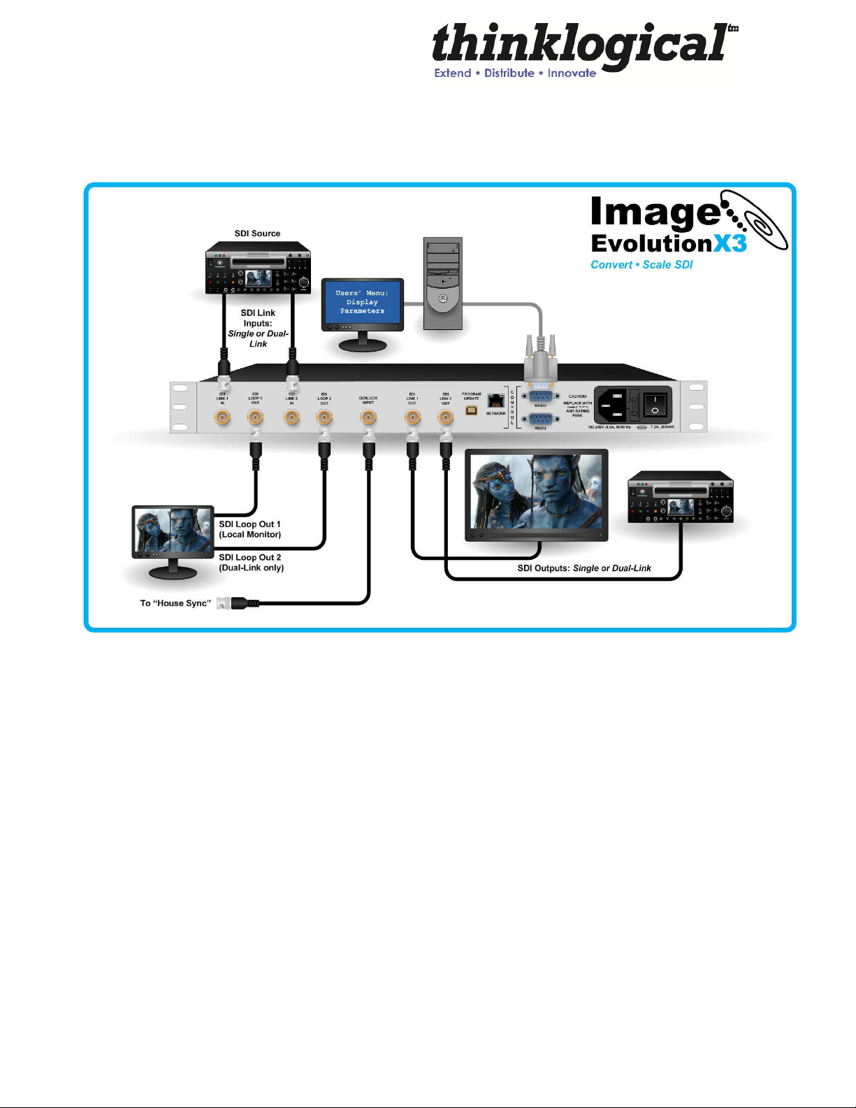
4. Installation
Image Evolution Setup:
1. In the case of a single link SDI or HD-SDI, or dual link HD-SDI source, coax
cable(s) may be connected between the Image Evolution’s Link1 IN (or in the case of
dual link, Link1 and Link2 IN), and an HD-SDI source. If desired, coax cables may
be connected between the Link1 (or Link1 and Link2) LOOP BACK BNC connectors
and a suitable monitor (or monitors). Loop back outputs will provide a raw or
unprocessed output of the video input on LINK1 IN or LINK2 IN.
2. If single or dual link HD-SDI is the desired output, connect coax cables between
the BNC connector(s) LINK1 OUT (or LINK1and LINK2 OUT) and a suitable monitor
(or monitors). LINK1 OUT and LINK2 OUT provide processed output of the video
input.
3. Connect CAT-5 cable between the RJ-45 on the Image Evolution and 10/100
Ethernet port if a network is available. (Available in future firmware updates)
4. The USB on the Image Evolution need not be connected at this point. Note:
When performing a firmware upgrade it is recommended that the IEX3 be restored
Revision D 10 June 2011
Page 11

back to the factory default. (1080i @ 60 at 4:2:2 10-bit mode). See section on
'Restore Factory Config'
User Menu Configurations:
The IEX3 has many configuration options and Appendices A and B will cover these options in
detail. Every configuration can be set regardless of the user interface (e.g. RS-232, RS-422,
Front Panel Display, Web Interface).
5. Regulatory and Safety
5.1 Safety Requirements
5.1.1 Symbols Found on Product
Markings and labels on the product follow industry-standard conventions. Regulatory markings
found on the products comply with requirements.
5.2 Regulatory Compliance
The Thinklogical Inc. products are designed and made in the USA. Our products have been
tested by a nationally recognized testing laboratory and found to be compliant with the following
standards (both domestic USA and many international locations).
5.2.1 North America
These products WILL comply with the following standards:
Safety
• ANSI/UL60950-1: 1st Edition (2003)
• CAN/CSA C22.2 No. 60950-1-03
Electromagnetic Interference
• FCC CFR47, Part 15, Class A
• Industry Canada ICES-003 Issue 2, Revision 1
5.2.2 Australia & New Zealand
This is a Class A product. In a domestic environment this product may cause radio interference,
in which case the user may be required to take adequate measures.
Revision D 11 June 2011
Page 12

European Union
5.2.2.1 Declaration of Conformity
Manufacturers name and address:
Thinklogical LLC
100 Washington Street
Milford, CT 06460 USA
Telephone (203)647-8700
• Model: ImageEvolution X3
Product name
This product complies with the requirements of the Low Voltage Directive 72/23/EEC and
the EMC Directive 89/336/EEC.
5.2.2.2 Standards with which the Products Comply
Safety
• CENELEC EN 60950-1, 1st Edition (2001)
Electromagnetic Emissions
• EN55022: 1994 (IEC/CSPIR22:1993)
• EN61000-3-2/A14:2000
• EN61000-3-3:1994
Electromagnetic Immunity
• EN55024:1998 Information Technology Equipment-Immunity Characteristics
• EN61000-4-2:1995 Electro-Static Discharge Test
• EN61000-4-3:1996 Radiated Immunity Field Test
• EN61000-4-4:1995 Electrical Fast Transient Test
• EN61000-4-5:1995 Power Supply Surge Test
• EN61000-4-6:1996 Conducted Immunity Test
• EN61000-4-8:1993 Magnetic Field Test
• EN61000-4-11:1994 Voltage Dips & Interrupts Test
Revision D 12 June 2011
Page 13

5.2.3 Supplementary Information
The following statements may be appropriate for certain geographical regions and might not
apply to your location.
Note
Note
This Class A digital apparatus meets all requirements of the Canadian Interference-Causing
Equipment Regulations.
Cet appareil numerique de la classe A respecte toutes les exigencies du Reglement sur le
material brouilleur du Canada.
: This equipment has been tested and found to comply with the limits for a
Class A digital device, pursuant to part 15 of the FCC Rules. These limits are
designed to provide reasonable protection against harmful interference when the
equipment is operated in a commercial environment. This equipment generates,
uses and can radiate radio frequency energy and, if not installed and used in
accordance with the instruction manual, may cause harmful interference to radio
communications. Operation of this equipment in a residential area is likely to
cause harmful interference in which case the user will be required to correct the
interference to radio communications at his own expense.
: This Class A digital apparatus complies with Canadian ICES-003 and has
been verified as being compliant within the Class A limits of the FCC Radio
Frequency Device Rules (FCC Title 47, Part 15, Subpart B Class A), measured to
CISPR 22: 1993 limits and methods of measurement of Radio Disturbance
Characteristics of Information Technology Equipment.
Warning!
Note:
electromagnetic fields.
This is a Class A product. In a domestic environment this product may
cause radio interference, in which case the user may be required to take
adequate measures.
The user may notice degraded audio performance in the presence of
5.2.4 Product Serial Number
Thinklogical products have a unique serial number, imprinted on a small silver label that is
placed on the bottom of the chassis. The serial number includes a date-code. The format for
the date-code is two digits for the month; two digits for the day and four digits for the year and
two or three digits for a unique unit number. This serial number is also found on the original
shipping carton.
Revision D 13 June 2011
Page 14

6. How to Contact Us
6.1 Customer Support
Thank you for choosing a Thinklogical product for your application. We appreciate your
business and are interested in helping you successfully use our product. Thinklogical is here to
help you.
Thinklogical is an engineering company; you receive the information you require from the key
engineer. We believe that the first line of support is the design engineer that developed the
product. Therefore, your questions will be handled promptly by an engineer.
To contact Thinklogical, use the following telephone numbers and internet-based methods.
6.1.1 Website
Check out our website for current product offerings, support information and general information
about all of the products we offer.
Our internet website offers product information on all current systems, including technical
specification sheets and installation guides (for viewing online or for download), product
diagrams showing physical connections and other information you might need.
Internet: www.thinklogical.com
Note:
not have the Adobe Acrobat reader needed to view PDF files, visit www.adobe.com for a
download.
Most online documents are stored as Adobe Acrobat “PDF” files. If you do
6.1.2 Email
Thinklogical is staffed Monday through Friday from 8:30am to 5:00pm, Eastern Time Zone. We
will try to respond to your email inquiries promptly, use the following email addresses for your
different needs:
info@thinklogical.com – Information on Thinklogical and our products.
sales@thinklogical.com – Sales Department - orders, questions or issues.
support@thinklogical.com – Product support, technical issues or questions, product
repairs and request for Return Authorization.
Revision D 14 June 2011
Page 15

6.1.3 Telephone
Telephone Sales: Contact our expert, technically oriented sales staff via telephone in Milford,
CT at (203) 647-8700 or if in the continental US, you may use our toll-free number (800) 291-
3211. We are here Monday through Friday from 8:30am to 5:00pm, Eastern Time Zone. Ask
for their direct dial phone number when you call.
Telephone Product Support: Contact Product Support via telephone in Milford, CT at (203) 647-
8700. The support lines are manned Monday through Friday, 9am to 5pm, Eastern Time Zone.
International Sales: Please contact our US sales staff in Milford, CT at (203) 647-8700. We are
here Monday through Friday, 8:30am to 5:00pm, Eastern Time Zone (same as New York City).
If leaving a voice message, please provide a “best time to call back” so we may reach you at
your convenience.
Our switchboard attendant will direct your call during regular business hours. We have an
automated attendant answering our main telephone switchboard after regular business hours
and holidays. You can leave voice messages for individuals at any time. Our Sales
Representatives have direct numbers to speed up your next call to us.
6.1.4 Fax
Our company facsimile number is (203) 783-9949. Please indicate the nature of the fax on your
cover sheet and provide return contact information.
6.1.5
Thinklogical’s support personnel are available Monday through Friday from 8:30am to 5:00pm,
Eastern Time Zone. If your application might require assistance at some time outside of our
normal business hours, please contact us beforehand and we will do our best to make
arrangements to help you with your Thinklogical products.
6.1.6 Warranty
Thinklogical, LLC (“Thinklogical”) warrants this product against defects in materials and
workmanship for a period of one (1) year from the date of delivery (ordinary wear and tear
excluded). This limited warranty does not cover defects resulting from (i) use of the product
other than as described in the applicable documentation for the product; (ii) modifications to or
repairs of the product that are made by any party other than Thinklogical or a party acting on
Thinklogical’s behalf, or (iii) combination of the product with third party products that is not
consented to by Thinklogical. Occurrences of events described in (i) – (iii) shall void the
foregoing warranty. This warranty gives you specific legal rights, and you may also have other
rights which vary from state to state.
Product Support
Except for the express warranty set forth above, to the fullest extent permitted under
applicable law, Thinklogical, LLC and its suppliers disclaim any and all other warranties,
express and implied, including without limitation the implied warranties of
merchantability, fitness for a particular purpose, title and non-infringement.
Revision D 15 June 2011
Page 16

If the defective product is returned to the authorized dealer within one (1) year of the delivery
date, repair or replacement of the product will be made. Repairs may be made with refurbished
parts. If repair or replacement is not possible, Thinklogical may keep the defective product and
refund the amount that you paid for the defective product. These are Thinklogical’s sole
obligations, and your exclusive remedies, for a breach of the limited warranty set forth above.
To return a defective product, contact the Thinklogical authorized dealer from whom you
purchased the product. Do not return a product directly to Thinklogical without prior
authorization from your dealer.
If you have received prior authorization from your dealer and are returning a product directly to
Thinklogical:
1. Contact your sales representative, or call Customer Support at (800)291–3211 or +
(203)647–8700.
2. Describe the defect with the product and Customer Support will issue a Return
Merchandise Authorization Number (RMA#).
3. Pack the product in all of its original packing, if possible, and write the RMA number
on the box.
4. Return the product to:
Thinklogical, LLC
Attn: RMA# [Insert the RMA# issued to you, by Thinklogical, here.]
100 Washington Street
Milford, CT 06460 USA
Note: Extended warranties are available from Thinklogical at an additional cost. Contact your
sales representative for further information and pricing.
6.1.7 Our Address
If you have any issue with the product, have product questions or need technical assistance
with your Thinklogical® system, please call us at 800-291-3211 (USA only) or (203) 647-8700
and let us help. If you’d like to write us, we are located at:
Thinklogical LLC
100 Washington Street
Milford, CT 06460 USA
Revision D 16 June 2011
Page 17

APPENDIX A
A.1. GUI
The graphical user interface (GUI) for the IE X3 was developed for ease of use to create, set,
and recall custom configurations. There are 6 main menus that allow you to configure the
input/output, video processor, audio, user configurations, system settings and system
information. There are sub-menus under the video processor menu for video control and
picture control.
Note- When power has been cycled on a unit it will reset to factory settings unless the “Set
Power On Config” has been set in the User Menu.
Input/Output Menu
This menu allows you to select the input and the format of the output. There is also an option to
select the 3D output as well as Enable Genlock, Enable Ancillary Time Codes, and Enable
Ancillary closed caption.
By clicking the “Take” button at the bottom of the screen you are able to commit the settings that
you have selected.
Revision D 17 June 2011
Page 18

Video Processor > Video Control
Compression Artifact Reducer, Edge Enhancer, and Adaptive Contrast Enhancer.
The video control sub-menu allows you to control De-Interlacer, Noise Reducer,
Video Processor > Picture Control
The picture control sub-menu allows you to control Hue Saturation, Advanced Color
Remapping, Flesh Tone Correction and Color Temperature. You can also reset all levels back
to the factory default.
Revision D 18 June 2011
Page 19

Audio
The audio menu allows you to select which output audio channel is sourced with any input audio
channel. It also allows you to enter an audio delay (from -50 ms to +50 ms) when needed.
User
The user menu allows you to save your current configuration by name or restore factory
configuration. You can also use the drop down menu to “Select Config Name” and set power on
configuration (which sets the current configuration to be the default power on configuration),
restore factory configuration and delete the selected configuration.
Revision D 19 June 2011
Page 20

System Set
The system set menu allows you to view the IP address, Mask and Gateway of the unit in use.
From this menu you can also select either RS-232 or RS-422 as the serial port. You must hit
the “Save/Apply” button to save your changes.
The IP address, Mask, and Gateway can all be changed via RS-232/RS-422 control or via the
front panel only. The fields are read-only on the GUI.
System Info
The system info menu allows you to view information for the inputs and outputs as well as
Genlock and software and firmware versions.
Revision D 20 June 2011
Page 21

APPENDIX B
There are a lot of status and configuration settings that can be viewed but are not output to the
Front Panel display due to the display limitations. The RS-232 and RS-422 interface menus will
have an 'exit' option. Selecting this option will display the menu items one level up. The SPACE
bar will repeat the current menu and the ENTER key will return the user to the top level menu.
This document will be formatted similar to how the configuration menus are displayed on powerup.
The RS-232 setup and configuration is as follows:
MAIN USER MENU:
B.1. RS-232, RS-422, Front Panel Display
• Use Hyperterm or similar type interface.
• Baud rate is 115200, 8 bits, no parity, 1 stop bit, no flow control
• Emulate VT-100 mode
A: Set Input Select
B: Set Output Select
C: Video Processing Setup
D: Audio Info and Setup
E: User Config Setups
F: System Settings
G: System Information
Revision D 21 June 2011
Page 22

MAIN MENU:
A: Set Input Select
Note:
output line-by-line, side-by-side, or rate-converted Dual Stream.
A valid input must be applied in order for the configuration to be used.
a: Single Link Input 1
Selects the video and embedded audio source from BNC Input 1. This will select
the video signal to be processed from link 1. Note: This is also the default link
and does not have to be selected when configuring the output video format.
Signal does need to be present for configuration to be successful.
b: Single Link Input 2
Selects the video and embedded audio source from BNC Input 2.
c: Dual Link
Selects a Dual link Video and embedded audio source on BNC Inputs 1 and 2.
d: Dual Stream 3D
Inputs 1 & 2 are to be used for Left Eye / Right Eye signals for 3D processing for
e: Enable Loop 1 Output
This will enable the video signal applied to input 1 to be looped back out of the
IEX3. This is enabled as default.
f: Disable Loop 1 Output
Turns off the BNC Loop output 1.
g: Enable Loop 2 Output
This will enable the video signal applied to input 2 to be looped back out of the
IEX3. This is enabled as default.
h: Disable Loop 2 Output
Turns off the BNC Loop output 2.
i: AUTO mode ON
Detects when a video source has changed format. On cable insertion, the unit
performs a re-configuration of the last known output setting with the new input.
j: AUTO Mode OFF
Turns off the AUTO mode.
j: Right Half Frame (3D to 2D)
This feature will scale the right half side of the input video and display it as full
screen.
Revision D 22 June 2011
Page 23

MAIN MENU:
B: Set Output Select
Note: Items in this menu will configure the output video format. The video coming
out of the IEX3 is duplicated on both ports with the exception of Dual Link mode.
By selecting any of the following formats, this becomes the default configuration on all
subsequent power cycle iterations.
a: Standard Def. Output
Selects the menu for Standard Definition video output format.
b: High Definition Output
Selects the menus for High Definition video output format.
c: HD Dual Link Output
Selects the menus for Dual Link video output. format.
d: 3G Level A Output
Selects the menus for 3G Level A video output format.
e: 3G Level B Output
Selects the menus for 3G Level B video output format.
Revision D 23 June 2011
Page 24

MAIN MENU:
C: Video Processing Setup
a: Comp. Artifact Reducer
Selects the menu for Component Artifact Reducer (CAR) video processing
functions.
b: DeInterlacer
Selects the menus for the DeInterlacer (DEINT) video processing functions.
c: Noise Reducer
Selects the menus for the Noise Reduction (NR) video processing functions.
d: Picture Control
Selects the menus for Picture Control (PC) video processing functions.
e: Edge Enhancer
Selects the menus for Edge Enhancement (EE) video processing functions.
f: Color Management Unit
Selects the menus for Color Management Unit (CMU) video processing
functions.
g: Adapt. Contrast Enhancer
Selects the menus for the Adaptive Contrast Enhancer (ACE) video processing
functions.
h: 3D Control Menu
Selects the menu for output 3D processing formats.
Revision D 24 June 2011
Page 25

MAIN MENU:
D: Audio Info and Setup
a: Enable Audio Output
Enables the embedded audio output from the selected input.
b: Disable Audio Output
Mutes all embedded audio output channels.
c: Get Audio Info Input 1
Get Audio information from BNC Input 1.
d: Get Audio Info Input 2
Get Audio information from BNC Input 2.
e: Set Audio Delay
Audio Delay range is from -50 - +50 in mS with the default being 0.
f: Get Audio Delay
The programmed Audio Delay in mS.
g: Get Audio Channel Cfg.
Get the audio channel mapping.
h: Assign Audio Channels
Configure input to output channel configuration.
Revision D 25 June 2011
Page 26

MAIN MENU:
E: User Config Setups
a: Save Current Config
Saves the current system settings to the non-volatile Memory. Maximum of 20
characters for the record name.
b: Set Power On Config
This option will set the current configuration to the user in-accessable region of
flash. This configuration is restored during power up.
c: Restore Config Record
Recall any one of the current saved configuration records.
d: Restore Factory Config
By selecting this, the IEX3 will delete the stored power on configuration.
configuration and will re-configure to the factory default on the next power cycle
(1080i @ 60 Hz). Another way to achieve this is to hold down the front panel
knob for a minimum of 5 seconds during a power cycle.
e: Erase Record(s)
Erase a particular record or all records.
Revision D 26 June 2011
Page 27

MAIN MENU:
F: System Settings
a: Genlock Enable
A valid 'House Sync' needs to be applied to this input before enabling.
b: Genlock Disable
Disables GenLock.
c: Serial Port Select
Selects between the RS-232 and the RS-422 serial port communications
interfaces.
Note: Communication can be lost if switching away from the
current active communications port!
d: Ethernet Settings
Settings for the network interface.
e: Ancillary Data Settings
Enable/Disable Closed Captioning (DID=0x61, SDID=0x1) and Time Code
(DID=0x60, SDID=0x60) data as well as a user configurable DID/SDID pair. Note
that the user configurable pair will pass data at the incoming frame rate
regardless of the configured output frame rate. The Time Codes and Closed
Captioning info is processed to compensate for different input/output frame rates.
Note:
all frame rates. However, only the 608 data packet contents within the
CDP708 are forwarded (708 data contents shall be overwritten with inactive
padded data). IEX3 will handle the contents of CDP708 data in release TBD.
f: Perform Lamp Test
Verify the 9 front panel LED's for proper operation.
IEX3 supports SMPTE 334 CDP708 data stream processing for
Revision D 27 June 2011
Page 28

MAIN MENU:
G: System Information
The following is used for retrieving information regarding current setup and signal
detection information. The 'Get Genlock Info' is not available for display on the Front Panel. The
'Get Input X', 'Get Output Info' will display the signal format only on the Front Panel whereas the
other communications interfaces will display more verbose info.
a: Get Software Version
Displays the System’s software version number.
b: Get FPGA 1 Version
Displays FPGA 1 version number
c: Get FPGA 2 Version
Displays FPGA 2 version number
d: Get Local Temperature
Displays the temperature inside the box
e: Get Input 1 Info
Displays Information about the video and embedded audio signal on BNC Input 1
f: Get Input 2 Info
Displays Information about the video and embedded audio signal on BNC Input 2
g: Get Output Info
Displays Information about the video and embedded audio signal on BNC
Outputs
h: Get Genlock Info
Displays Information about the incoming Genlock signal on BNC Genlock Input
Revision D 28 June 2011
Page 29

MAIN MENU:
B: Set Output Select
SUB-MENU:
a: Standard Def. Output
Selects a SD output format type of the selected resolutions:
a: 480i @ 59.94 (525-270)
b: 576i @ 50 (625–270)
Revision D 29 June 2011
Page 30

MAIN MENU:
B: Set Output Select
SUB-MENU:
b: High Definition Output
Selects a HD output format type of the selected resolutions:
a: 720p @ 23.97
b: 720p @ 24
c: 720p @ 25
d: 720p @ 29.97
e: 720p @ 30
f: 720p @ 50
g: 720p @ 59.94
h: 720p @ 60
i: 1035i @ 59.94
j: 1035i @ 60
k: 1080i @ 50
l: 1080i @ 59.94
m: 1080i @ 60
n: 1080p @ 23.97
o: 1080p @ 24
p: 1080p @ 25
q: 1080p @ 29.97
r: 1080p @ 30
s: 1080psf @ 23.97
t: 1080psf @ 24
u: 1080psf @ 25
v: 1080psf @ 29.97
w: 1080psf @ 30
Note: All HD outputs are 10 bit YCbCr 4:2:2
Revision D 30 June 2011
Page 31

MAIN MENU:
B: Set Output Select
SUB-MENU:
c: HD Dual Link Output
Selects a HD-DL output format type of the selected resolutions:
a: 1080i @ 50
b: 1080i @ 59.94
c: 1080i @ 60
d: 1080p @ 23.97
e: 1080p @ 24
f: 1080p @ 25
g: 1080p @ 29.97
h: 1080p @ 30
i: 1080p @ 50 4:2:2 10b
j: 1080p @ 59.94 4:2:2 10b
k: 1080p @ 60 4:2:2 10b
l: 1080sf @ 23.97
m: 1080sf @ 24
n: 1080sf @ 25
o: 1080sf @ 29.97
p: 1080sf @ 30
1080p50, 1080p59.94, and 180p60 can only be YCbCr 4:2:2 10 bit.
All other resolutions will proceed to a sub-menu for color space and bit width selection.
Revision D 31 June 2011
Page 32

MAIN MENU:
B: Set Output Select
SUB-MENU:
d: 3G Level A Output
Selects a 3G Level A output format type of the selected resolutions:
a: 1080i @ 50
b: 1080i @ 59.94
c: 1080i @ 60
d: 1080p @ 23.97
e: 1080p @ 24
f: 1080p @ 25
g: 1080p @ 29.97
h: 1080p @ 30
i: 1080p @ 50 4:2:2 10b
j: 1080p @ 59.94 4:2:2 10b
k: 1080p @ 60 4:2:2 10b
l: 1080sf @ 23.97
m: 1080sf @ 24
n: 1080sf @ 25
o: 1080sf @ 29.97
p: 1080sf @ 30
1080p50, 1080p59.94, and 180p60 can only be YCbCr 4:2:2 10 bit.
All other resolutions will proceed to a sub-menu for color space and bit width selection.
Revision D 32 June 2011
Page 33

MAIN MENU:
B: Set Output Select
SUB-MENU:
e: 3G Level B Output
Selects a 3G Level B output format type of the selected resolutions:
a: 1080i @ 50
b: 1080i @ 59.94
c: 1080i @ 60
d: 1080p @ 23.97
e: 1080p @ 24
f: 1080p @ 25
g: 1080p @ 29.97
h: 1080p @ 30
i: 1080p @ 50 4:2:2 10b
j: 1080p @ 59.94 4:2:2 10b
k: 1080p @ 60 4:2:2 10b
l: 1080sf @ 23.97
m: 1080sf @ 24
n: 1080sf @ 25
o: 1080sf @ 29.97
p: 1080sf @ 30
1080p50, 1080p59.94, and 1080p60 can only be YCbCr 4:2:2 10 bit.
All other resolutions will proceed to a sub-menu for color space and bit width selection.
Revision D 33 June 2011
Page 34

Menu after Dual Link/3G A/ 3G B resolution selection:
Output DL/3G Color Space/Bits Menu
Selects the output color space (YCbCr or RGB) and the bit width (10 or 12 bits):
a: YCbCr 4:4:4 10b
b: YCbCr 4:4:4 10b
c: YCbCr 4:4:4 10b
d: RGB 4:4:4 10b
e: RGB 4:4:4 10b
Revision D 34 June 2011
Page 35

MAIN MENU:
C: Video Processing Setup
SUB-MENU:
a: Comp. Artifact Reducer
This feature is used to reduce compression artifacts that are caused by video
compression schemes such as MPEG2. Mostly used on YCbCr 4:2:2 interlaced or
progressive input video.
a: Comp. Arti. Reducer EN
Enables the Compression Artifact Reducer.
b: Mosq. Noise Reducer EN
Enables the Mosquito (Ringing) Noise Reducer.
c: Block Noise Reducer EN
Enables the Block (8x8) Noise Reducer.
d: Non Std Block Noise Det EN
Enables the Non-Standard Block Detection.
e: Enable All CAR Blocks
Enables All the above (A,B,C,D) Noise Reduction Blocks.
f: Disable All CAR Blocks
Disables All the Noise Reduction Blocks.
Revision D 35 June 2011
Page 36

MAIN MENU:
C: Video Processing Setup
SUB-MENU:
b: DeInterlacer
Selects the menu for the DeInterlacer (DEINT) video processing functions .
a: Deinterlacer BYPASS
Bypasses the deinterlacer (input is progressive).
b: Deint 2D VECTOR
Sets the Interlacer for 2D Vector mode (Interlaced input DEFAULT mode).
c: Deint 2D VECTOR AGGRES.
Sets the Interlacer for 2D Aggressive mode (Interlaced input).
d: Deint 3D FIXED
Sets the Interlacer for 3D fixed mode (Interlaced input).
e: Deint 3D Mo Adpt Vector
Sets the Interlacer for 3D Motion Adaptive Vector mode.
f: Deint 3D MA Vect Aggres
Sets the Interlacer for 3D Motion Adaptive Vector Aggressive mode.
g: Deint 3D MA Vect Linear
Sets the Interlacer for 3D Motion Adaptive Vector Linear mode.
h: DEINTERLACER DEFAULT
Sets the Interlacer for DEFAULT mode.
Revision D 36 June 2011
Page 37

MAIN MENU:
C: Video Processing Setup
SUB-MENU:
c: Noise Reducer
Selects the menus for the Video Noise Reduction (NR) video processing functions.
Used mostly on YCbCr 4:2:2 Input video.
a: Noise Reducer DISABLE
Disables the Noise Reduction block.
b: Noise Reducer 2D
Sets the Noise Reducer for 2D (Spatial) mode.
c: Noise Reducer 3D Fixed
Sets the Noise Reducer for 3D Fixed (Temporal) mode.
d: Noise Reducer 3D Adapt
Sets the Noise Reducer for 3D Adaptive (Temporal) mode.
e: Noise Reducer Default
Sets the Noise Reducer for Default mode.
f: Noise Reducer Automatic
Sets the Noise Reducer for Automatic mode.
Revision D 37 June 2011
Page 38

MAIN MENU:
C: Video Processing Setup
SUB-MENU:
d: Picture Control
a: Set All Levels Default
Restores Contrast, Brightness, Tint, Black, Color Temp levels to defaults.
b: Set Contrast Level
Enter the Contrast Level 0 to +10. The Default value is 10.
c: Set Brightness Level
Enter the Brightness Level -100 to +100. The Default value is 0.
d: Set Tint Level
Enter the Tint Level -180 to +180. The Default value is 5.
e: Set Black Level
Enter the Black Level 0 to +100. The Default value is 0.
f: Set Color Temperature
SUB MENU : Video Set Color Temperature Menu
a: Color Temperature NORMAL
Sets the color temp to 6500.
b: Set Color Temperature COOL
Sets the color temp to 8000.
c: Color Temperature WARM
Sets the color temp to 6000.
d: Color Temperature CUSTOM
Enter Color Temp Level 6000 to 8000 (Normal = 6500)
Revision D 38 June 2011
Page 39

MAIN MENU:
C: Video Processing Setup
SUB-MENU:
e: Edge Enhancer
Selects the menus for Edge Enhancement (EE) video processing functions.
a: Edge Enhancer OFF
b: Edge Enhancer LOW
c: Edge Enhancer MED
d: Edge Enhancer HIGH
Revision D 39 June 2011
Page 40

MAIN MENU:
C: Video Processing Setup
SUB-MENU:
f: Color Management Unit
Selects the menus for Color Management Unit (CMU) video processing functions.
a: Hue Saturation Menu
Video Hue Saturation Menu
a: Hue Saturation ENABLE
b: Hue Saturation DISABLE
c: Intelligent Saturation ENABLE
d: Intelligent Saturation DISABLE
e: Set HUE Saturation Level
f: Set HUE Global Sat. Level
g: ICR Advanced Menu
Note: Hue saturation needs to be enabled (selection ‘a’) in order for
‘Set HUE Saturation Level’ (selection ‘e’) to be valid.
b: Qdeo True Color Menu
Video Qdeo Menu
a: Qdeo True Color OFF
b: Qdeo True Color SOFT
c: Qdeo True Color GENTILE
d: Qdeo True Color MEDIUM
e: Qdeo True Color HIGH
c: Film Grain Gain Menu
Video Film Grain Gain MENU
a: Disable Film Grain Gain
b: Set Film Grain Gain
Range is 0 - 255. Default is 0.
c: Set FGG Temporal Freq.
Range is 0 - 255. Default is 0.
d: Flesh Tone Correction
a: Set FTDC Preset Enable
b: Set FTDC Preset Level 1
c: Set FTDC Preset Level 2
d: Set FTDC Preset Level 3
e: Set FTDC Preset Level 4
f: Set FTDC Preset Level 5
g: Set FTDC Preset Level 6
h: Set FTDC Preset Disable
e: Set GAMMA Menu
a: GAMMA Disable
b: GAMMA 1.8
c: GAMMA 2.5
d: GAMMA S-Curve Light
e: GAMMA S-Curve Dark
Revision D 40 June 2011
Page 41

MAIN MENU:
C: Video Processing Setup
SUB-MENU:
g: Adapt. Contrast Enhancer
Selects the menus for the Adaptive Contrast Enhancer (ACE) video processing
functions.
a: ACE PRESET OFF
b: ACE PRESET LOW
c: ACE PRESET MEDIUM
d: ACE PRESET HIGH
e: ACE PRESET RANGE 0-255
f: ACE PRESET RANGE 16-235
g: ACE Brightness Menu
a: Brightness DISABLE
b: Brightness DEFAULT
c: Brightness Taper Size
Enter Taper Size (16, 32, 64, 128, 256, 512).
d: Brightness Taper Side
Enter Taper Side Select (1,2).
e: Brightness Enhancement
Enter Enhancement Level (1 - 15).
f: Brightness Threshold 1
Enter Threshold 1 Level (0 - 1023).
g: Brightness Threshold 2
Enter Threshold 2 Level (0 - 1023).
Revision D 41 June 2011
Page 42

MAIN MENU:
C: Video Processing Setup
h: 3D Control Menu
a: Left/Right Frame Menu
Menu to functions that will allow the zooming in of an incoming 3D side-
by-side signal and display one half as a 2D image (left eye or right eye).
b: Line-By-Line Output Menu
Select output format of a line-by-line signal.
c: Disable Line-By-Line Output
Turns off the line-by-line feature.
d: Side-By-Side Output Menu
Select output format of a side-by-side signal.
e: Disable Side-By-Side Output
Turns off the side-by-side feature.
f: Dual Stream Output Menu
Select output format of a dual stream signal.
g: Enable Adaptive Clock
Factory Use.
h: Disable Enable Adaptive Clock
Factory Use.
Revision D 42 June 2011
Page 43

MAIN MENU:
C: Video Processing Setup
h: 3D Control Menu
a: Left/Right Frame Menu
Left/Right Frame (3D) – Right Half Zoom (3D → 2D)
This feature enables the conversion of a 3d left/right image input (two full HD
images from left and right cameras are squeezed horizontally into a regular HD
frame) to a 2d right image output (any format). Input modes supported: HD-SDI
(720p, 1080i, 1080p) & 3G-SDI Level A.
SUB-MENU:
a: Enable Right Half 3D->2D
This will take the Horizontal Total width of the configured input and divide
this number by two and will stretch the right half of the input video signal
and display it full screen. This feature is enabled for HD-SDI (1080i,
1080p, 720p) & 3G-SDI Level A input modes.
b: Disable Right Half
Disables Right Half Frame mode and Re-formats the input to display the
full input frame.
c: Adjust Right Half 3D->2D
This will fine tune the half-way point of the input video. Only even values
are valid and if an odd value is entered, the software will round down
by one. This is to keep the color space bits aligned.
Revision D 43 June 2011
 Loading...