

Page 1
router
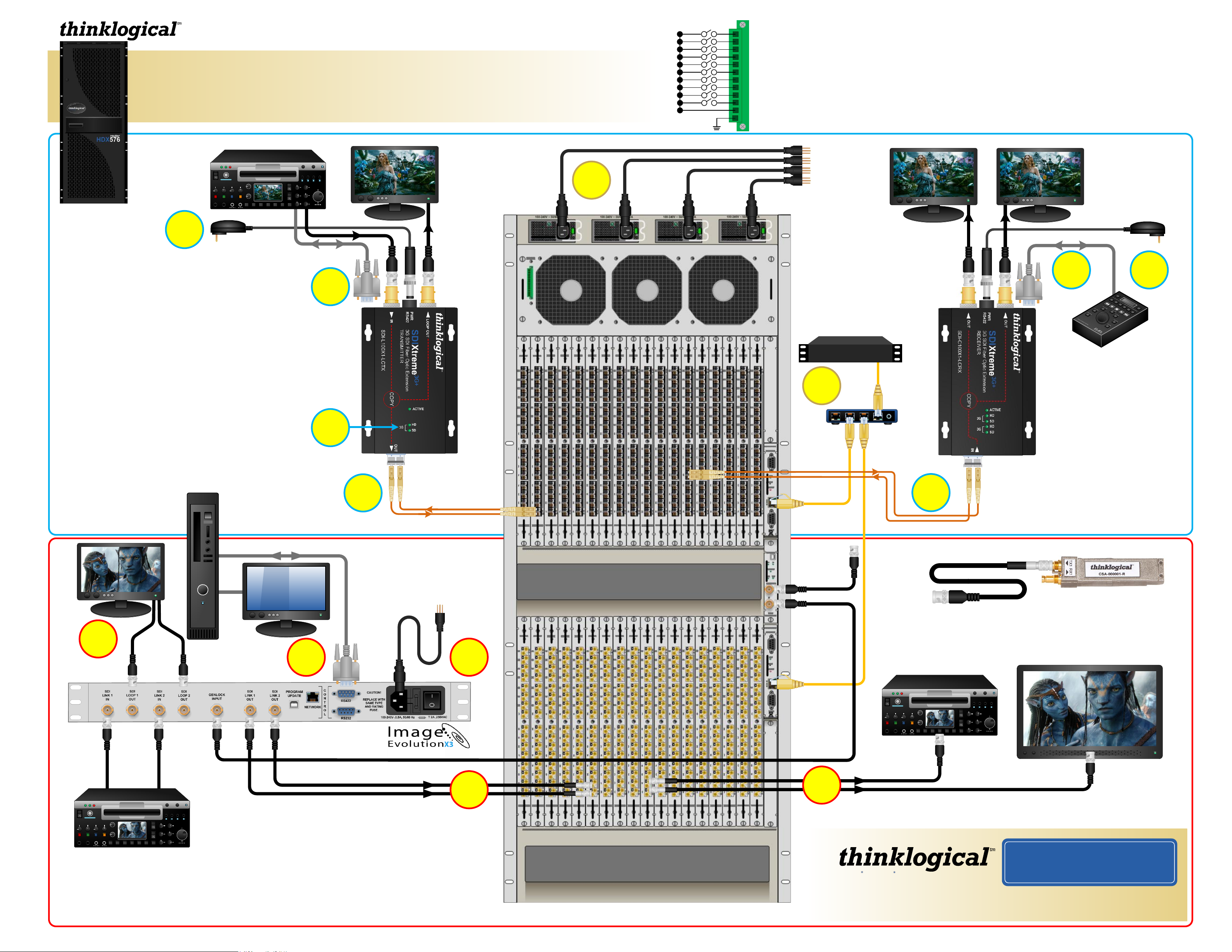
HDX576
QUICK-START GUIDE
QUICK-START GUIDE
As used with the SDIXtreme and the Image EvolutionX3
3G+
10
11
12
1
2
3
4
5
6
7
8
9
The HDX576 Router Critical Hardware Alarms: (Located at the top, left rear of the unit.)
POWER SUPPLY 1 (LEFT):
POWER SUPPLY 2:
POWER SUPPLY 3:
POWER SUPPLY 4 (RIGHT):
Individual fan monitoring
FANS:
TEMPERATURE WARNING:
TEMPERATURE SHUTDOWN:
Card failure (Only with a redundant card)
CPU:
INPUT/OUTPUT CARDS:
ANY OF THE ABOVE
COMMON
GROUND
Fan failure, temperature spikes, DC voltage and/or current out of range, AC power input interruption or module removed
Fan failure, temperature spikes, DC voltage and/or current out of range, AC power input interruption or module removed
Fan failure, temperature spikes, DC voltage and/or current out of range, AC power input interruption or module removed
Fan failure, temperature spikes, DC voltage and/or current out of range, AC power input interruption or module removed
Chassis over temperature, multiple sensors
Chassis over temperature causing shutdown
SFP+ failure, laser output fault
SDI Source
1 2 3 4 5 6 7
5
STEP 4: Connect your SDIXtreme 3G+ Transmitter to the HDX576
using multi-mode fiber optic cables. Connect the Transmitter’s
Fiber OUT to the Receive Port on any SFP of the Upper Card Cage.
If using RS422, a second, back-channel Fiber IN to the Transmitter
is required and should be connected to the same numbered Upper
Card Cage Transmit Port.
STEP 5: Install the provided +5VDC power supply into the
SDIXtreme 3G+ Transmitter and plug it into a standard AC source.
Ensure that the ACTIVE LED on the Transmitter comes on. The
ACTIVE LED will blink if no SDI input is present.
STEP 6: Connect your 3G, SD or HD SDI video source to the
SDIXtreme 3G+ Transmitter’s IN Port. A local Monitor or other
viewing device may be connected to the Transmitter’s LOOP OUT
port. If required, connect the Video Source’s RS422 port to the
Transmitter’s RS422 Port, located directly below the Power
connector.
+5V IN
1
2 3 4
RS422
6
7
SDI Loop Out (Local Monitor)
STEP 9: Install the provided AC
power cords into the HDX576
Power Supplies and plug them
into a standard AC source.
Ensure all system functions
are operating properly.
SDIXtreme
Transmitter
3G+
9
router
HDX576
26RU, 1700W
(fully loaded)
STEP 8: Connect the Controller
Cards’ LAN Ports to your
Controller CPU with CAT5 cables.
(CPU IP address: 192.168.13.9)
External Control CPU
8
Network
Hub
SDI Output 1 SDI Output 2
STEP 3: Install your HD, SD or 3G SDI
destination devices to the SDIXtreme
3G+ Receiver’s OUT Ports. If using
RS422, connect your device to the
Receiver’s RS422 port (located directly
below the Power Connector).
SDIXtreme
Receiver
RS422
STEP 2: Install the
provided +5VDC power
supply into the SDIXtreme
3G+ Receiver and plug it
into a standard AC source.
Ensure that the Receiver’s
ACTIVE LED comes on.
+5V IN
23
Machine
Controller
3G+
STEP 7: Ensure that the 3G, SD or HD LEDs are illuminated
(depending on your signal type). These indicate that the connections
are sound. Go to STEP 8.
RS422
Users’
DVI
CPU
Menu:
Display
Parameters
4
SDI Loop Out 1
(Local Monitor)
SDI Loop Out 2
(Dual-Link Only)
5
4
STEP 3: Install the provided AC power
cord into the Image EvolutionX3 and
plug it into a standard AC source. Turn
the Power Switch ON.
From Transmit Port
To Receive Port
3
From
Transmit Port
To Receive Port
Primary Controller
Card IP Address:
192.168.13.115
Sync Reference
Loop Out
STEP 1 (Fiber-Optic Cables): Connect
your SDIXtreme 3G+ Receiver to the HDX576 using
multi-mode fiber-optic cables (up to 1000 meters).
Connect the Receiver’s Fiber IN to the Transmit
1
75Ω Coax Cable
BNC connector
STEP 1 (75Ω Coax Cables): Connect your Single- or Dual-Link SDI device(s) to the
HDX576 using 75Ω Coax Cables terminated with BNC and DIN 1.0/2.3 connectors.
Connect each DIN 1.0/2.3 connector to the Transmit Port on any SFP in the Coaxial
I/O Modules of the Lower Card Cage and connect the BNC connectors to your SDI
input device(s). Turn the SDI Device(s) ON.
Port on any SFP of the Upper Card Cage. If using
RS422, a second, back-channel Fiber OUT to the
Transmitter is required and should be connected to
the same numbered Upper Cage Receive Port.
DIN 1.0/2.3 or
HD-BNC connector
Coaxial SFP
SDI Link
Inputs:
Single- or Dual-
Link
1
2 3 4
STEP 2: Connect your SDI Link 1 & Link 2 Outputs to the HDX576 using 75Ω Coax
Cables terminated with BNC and DIN 1.0/2.3 connectors. Connect each DIN 1.0/2.3
1 2 3 4 5 6 7
STEP 4: Using BNC Cables, connect your SDI devices to the SDI Loop OUT and SDI Link IN ports on the Image EvolutionX3
backpanel and turn the devices ON. Connect GENLOCK IN to SYNC REF IN on the HDX576. The SYNC REF LOOP OUT
can be connected to any other synchronized device.
STEP 5: Using an RS422 Serial Cable, connect your CPU to the Image EvolutionX3 backpanel. Using a standard DVI Cable,
connect a local viewing device to the CPU. Turn both devices and the CPU ON. Go to STEP 8.
connector to the Receive Port on any SFP in the Coaxial I/O Modules of the Lower
Card Cage.
1
2
To Sync Reference IN
To Receive Ports
SDI Outputs: Single- or Dual-Link
2
2
1
HDX576_SDIXtreme3G+_ImageEvolution_QSG_Rev_A
Copyright © 2011. All rights reserved. Printed in the U.S.A. All trademarks and service marks are the property of their respective owners.
Optional
Secondary
Controller Card
IP address:
192.168.13.116
2
1
1
From Transmit Ports
SDI Inputs: Single- (shown) or Dual-Link
Extend Distribute Innovate
Visit us online at www.thinklogical.com for more product information,
current updates and the complete line of Thinklogical™ products.
1 2 3 4 5 6 7
2
1
2 3 4
1
PHONE: 1-800-291-3211
WEBSITE: www.thinklogical.com
EMAIL: support@thinklogical.com
 Loading...