

Page 1
Page 2

H D M I t o 3 G S D I C o n v e
r
t e r P r o d u c t M a n u a l , R e v . B
Page
2
Copyright Notice
Copyright © 2013. All rights reserved. Printed in the U.S.A.
Thinklogical, LLC®
100 Washington Street
Milford, Connecticut 06460 U.S.A.
Telephone: 1-203-647-8700
All trademarks and service marks are property of their respective owners.
Subject: HDMI to 3G SDI Converter (+ Audio) Product Manual
Revision: B, April 2013
Page 3

H D M I t o 3 G S D I C o n v e
r
t e r P r o d u c t M a n u a l , R e v . B
Page
3
Table of Contents
PREFACE................................................................................................................................................ 4
Conventions Used in this Manual ..................................................................................................... 4
Laser Information ............................................................................................................................... 4
1 Introduction ....................................................................................................................................... 5
1.1 Contents ...................................................................................................................................... 5
1.2 Product Overview ....................................................................................................................... 5
2 System Features ................................................................................................................................ 5
2.1 General System Features .......................................................................................................... 5
2.2 Technical Specifications ............................................................................................................ 7
3 Connecting the HDMI to 3G SDI Converter ...................................................................................... 8
3.1 Types of Connections ................................................................................................................ 8
3.1.1. SFP+ Modules (
3.1.2 Fiber Optic Cable (
3.1.3. RS-232 Pin Out ................................................................................................................ 9
3.1.4. RS-422 Pin Out (
3.2. Set Up ........................................................................................................................................ 10
3.3 Desktop ..................................................................................................................................... 11
3.4 Cooling ...................................................................................................................................... 11
Extension Option Only
Extension Option Only
Extension Option Only
) .............................................................................. 8
) ......................................................................... 9
) ............................................................................. 9
4 General Front Panel Usage ............................................................................................................. 11
4.1 User Menu Configurations ....................................................................................................... 12
5 Regulatory & Safety Compliance .................................................................................................... 12
5.1 Safety Requirements ................................................................................................................ 12
Symbols found on the product ........................................................................................................ 12
5.2 Regulatory Compliance ........................................................................................................... 12
North America ................................................................................................................................ 12
Australia & New Zealand ................................................................................................................ 12
European Union ............................................................................................................................. 12
5.3 Standards with Which Our Products Comply ......................................................................... 13
5.4 Supplementary Information ..................................................................................................... 13
5.4.1. Product Serial Number ........................................................................................................ 14
5.4.2. Connection to the Product ................................................................................................... 14
6 How to Contact Us ........................................................................................................................... 14
6.1 Customer Support .................................................................................................................... 14
6.1.1. Website ............................................................................................................................... 14
6.1.2. Email ................................................................................................................................... 15
6.1.3. Telephone ........................................................................................................................... 15
6.1.4. Fax ...................................................................................................................................... 15
6.2 Product Support ....................................................................................................................... 15
6.2.1. Warranty .............................................................................................................................. 16
6.2.2. Return Authorization ............................................................................................................ 16
APPENDIX A: HDMI to 3G SDI Application Drawings ........................................................................ 17
APPENDIX B: HDMI to 3G SDI Converter QuickStart Guide ............................................................. 18
APPENDIX C: GUI ................................................................................................................................ 19
APPENDIX D: Front Panel Display and RS-232 .................................................................................. 23
APPENDIX E: Ordering Information .................................................................................................... 30
Page 4
H D M I t o 3 G S D I C o n v e
PREFACE
Conventions Used in this Manual
manual you will notice certain conventions that bring your
and
Important Notes appear in blue text preceded by a yellow exclamation point
note is meant to call the reader’s attention to helpful inf
Warnings appear in red text, followed by blue text, and preceded by a
red stop sign, like this.
A warning is meant to call the reader’s
BEFORE STARTING ANY PROCEDURE
THAT YOU READ THE INSTRUCTIONS THOROUGHLY
including
product
CLASS
precautions under conditions of normal use
r
t e r P r o d u c t M a n u a l , R e v . B
ormation at a point in the text that is relevant to
formation at a point in the text that is relevant
IT IS RECOMMENDED
designed and
LASERS do not require any special
Optic
Page
4
Throughout this
information. These are Notes
Note:
symbol, like this.
A
the subject being discussed.
Warning! All
to the subject being discussed.
Warnings. Examples are shown below.
attention to critical in
,
®
attention to important
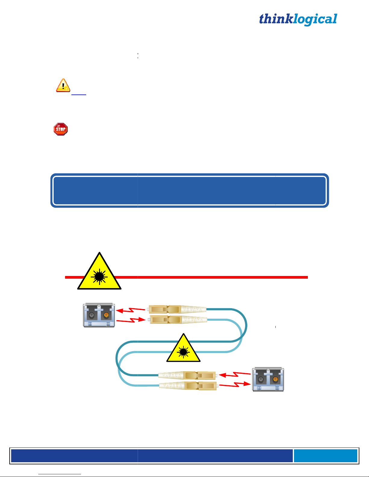
Laser Information
Many Thinklogical® products,
identified as
Class 1 LASER
SFP
Modules
the HDMI to 3G SDI Converter,
s.
1
Class 1 Lasers
are
FiberCables
!
.
Page 5
H D M I t o 3 G S D I C o n v e
r
t e r P r o d u c t M a n u a l , R e v . B
Page
5
1 Introduction
1.1 Contents
When you receive your Thinklogical® HDMI to 3G SDI Converter, you should find the following items:
• HDMI to 3G SDI Converter (HDC-000001) or
HDMI to 3G SDI Converter with Xtreme 3G+ Extension Option (HDC-000001-LC)
• AC/DC adapter universal input 90-264 VAC (PWR-000022-R)
• +12VDC supply voltage
• HDMI to 3G SDI Converter Product Manual
• HDMI to DVI Male/Male Molex Cable (CBL000030-002MR, 2 meters)
1.2 Product Overview
The Thinklogical® HDMI to 3G SDI Converter is a stand-alone product that allows advanced real-time
image correction and scaling, while at the same time functioning as a video converter which supports an
HDMI or DVI input to an SDI output of SD/HD/3G SDI. The HDMI to 3G SDI Converter/Extender has a
fiber-optic output (which allows fiber extension up to 1000 meters) that is fully compatible with
our SDIXtreme3G+ line of receivers for a comprehensive conversion and extension solution.
H: 1.5” (38.1mm) x D: 7.75” (196.85mm) x W: 7.65” (136.65mm)
2 System Features
2.1 General System Features
Thinklogical’s® HDMI to 3G SDI Converter allows you to seamlessly convert an HDMI or DVI
signal to a broadcast quality SDI signal.
• Full SMPTE compliant
• Genlock input
• User interface options include:
Front panel LCD
Encoder
Remote control via the RS-232 Serial port
Ethernet port & device control via RS-422 Serial port (SDI Xtreme 3G+ Extension model).
• Audio inputs include:
HDMI embedded (up to 8 channels)
Digital AES (single stereo pair)
Balanced analog (single stereo pair)
• Audio outputs include SDI embedded (up to 8 channels).
Page 6
H D M I t o 3 G S D I C o n v e
r
t e r P r o d u c t M a n u a l , R e v . B
Page
6
The HDMI to 3G SDI Converter/Extender® with the fiber output option is fully compatible with the
Thinklogical SDI Xtreme 3G+® line of receivers for a comprehensive conversion and extension solution.
The SDI Xtreme 3G+ Extension version includes a Serial port (RS-422) and has the option using SingleMode or Multi-Mode over one or two fibers.
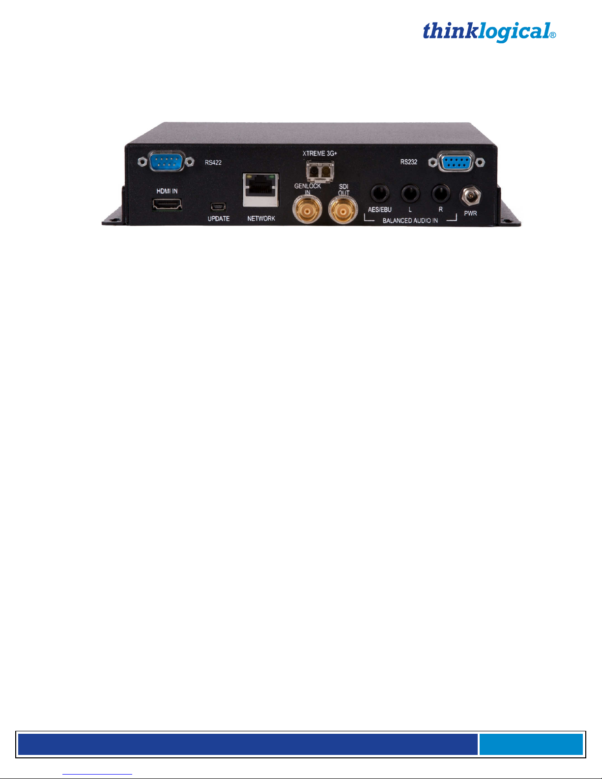
HDMI to 3G SDI Converter/Extender (with SDIXtreme3G+ Extension Option) rear panel view
Each HDMI to 3G SDI Converter system includes the following features:
Conversion/Scaling:
• Video Input: HDMI, DVI
• Audio Sources: HDMI embedded (up to 8 channels), Balanced analog (single stereo pair),
Balanced digital AES (single stereo pair)
• Video Output: SD-SDI (SMPTE 259M-C), HD-SDI (SMPTE 292), 3G (SMPTE 424M, 425
Level A and B)
• Audio Outputs: SDI embedded (up to 8 channels)
• Fiber optic output compatible with Thinklogical’s® SDI Xtreme 3G+ Receivers
• User Control via front panel, RS-232 and Ethernet (See page 11)
• Device Control via front panel, RS-422 for Camera Controller, PTZ, etc. (See pg. 11)
• Front panel LCD with encode knob
• SMPTE standards supported: 259M-C, 292, 424M, 425 level A and level B
• Genlock capable
• Automatic video input detection
Video Processor Features:
• Per pixel motion-adaptive video noise reduction- removes the white Gaussian noise present in
most types of video
• Content adaptive block and mosquito noise reduction- significantly reduces the blocking and
mosquito noise artifacts present in compressed video
• Advanced per-pixel, motion-adaptive, edge-adaptive 3D de-interlacing with support for arbitrary
film cadences- removes “jaggies” and “feathering” to produce smooth and clear images
• Adaptive scaling- produces sharp and clean images and low or high resolutions
• Natural dept expansion- enhances details and sensation of depth for greater realism and super
resolution effect
• Adaptive contrast enhancement (ACE) brings out shadow detail without crushing mid-tones or
highlights
• Intelligent color remapping (ICR) enables vivid color without hue shifts and clipping while
maintaining accurate flesh tone
• Qdeo™ true color- a unique solution for using the full dynamic range of 10-bit and 12-bit displays
which eliminates contouring seen when viewing typical 8-bit consumer video
Page 7

H D M I t o 3 G S D I C o n v e
r
t e r P r o d u c t M a n u a l , R e v . B
Page
7
2.2 Technical Specifications
Technical Specifications
Height: 1.5” (38.1 mm)
Dimensions
Depth: 7.75" (196.85 mm)
Width: 7.65" (136.65 mm) (Tolerance: ± .039"; .1000 mm)
Weights
Operating Temp
and Humidity
Power Consumption Converter: 10 watts per unit; Extender: 12 watts per unit
Supply Voltage +12.0 VDC
DC Adapter AC/DC adapter universal input, 90-264 VAC
Optical Distance
(Xtreme 3G+
Extension Option)
Compliance Approvals for US, Canada, and European Union
Warranty 12 months from date of shipment. Extended warranties available
Frame Rate Formats Supported: Progressive, Interlaced, PsF
Converter: 1 lb (0.45 kg); Extender: 1.5 lbs (0.68 kg)
Shipping Weight: 9 lbs (4.08 kg) pair
0° to 50°C (32° to 122 °F), 5% to 95% RH, non-conde nsing
Up to 50 meters with Type OM1
Up to 350 meters with Type OM2
Up to 750 meters with Type OM3
Up to 1000 meters with Type OM4
Up to 40 kilometers with Type OS2
Function Video Standards Supported Formats
SD-SDI SMPTE 259M PAL and NTSC
HD-SDI SMPTE 292M All standard HD-SDI compatible formats
3G SDI
SMPTE 424M, 425M,
Level A and B
All SMPTE 425 level A and B
compatible formats
Page 8
H D M I t o 3 G S D I C o n v e
r
t e r P r o d u c t M a n u a l , R e v . B
Page
8
3 Set-up and Connection of the HDMI to 3G SDI Converter
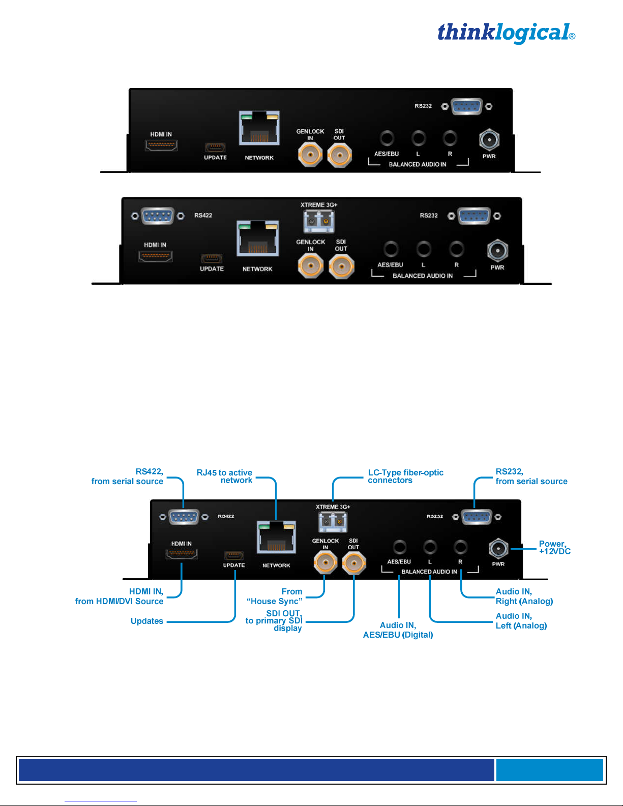
HDMI to 3G SDI Converter, rear panel (HDC-000001)
HDMI to 3G SDI Converter with Xtreme 3G+ Extension Option, rear panel (HDC-000001-LC)
3.1 Types of Connections
All physical connections to the product use industry-standard connectors. Non-supplied cables that may
be needed are commercially available. All interface connections are found on the rear of the unit.
Ports available on the HDMI to 3G SDI Converter:
• 19-pin HDMI • AES3 BNC • DB9 RS232 Serial
• 5-pin USB-B Mini • 3.5mm Audio • DB9 RS422 Serial (Extender option only)
• RJ45 CAT5 Serial • ¼” Threaded power jack • LC-Type Fiber-optic (Extender option only)
HDMI to 3G SDI Converter with Xtreme 3G+ Extension Option, connectors
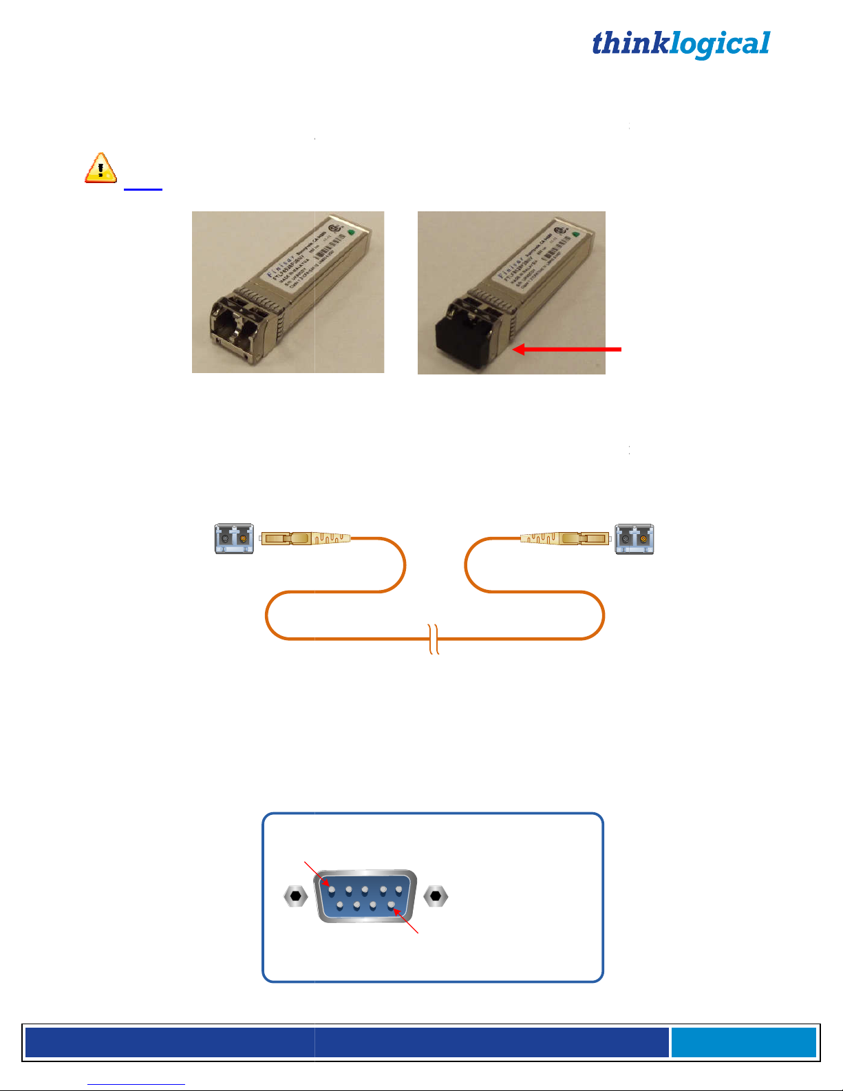
3.1.1. SFP+ Modules
The HDMI to 3G SDI Converter with the Xtreme 3G+ Extension Option contains an SFP+ module
that serves as the fiber-optic coupler for the fiber-optic cables to and from Thinklogical® extenders
and other devices.
(Extender option only)
Page 9
H D M I t o 3 G S D I C o n v e
Small Form-factor P
luggable modules are short
channel links. Each SFP module is hot
your unit is shipped, the SFP will have a dust plug installed.
plug for later use.
lug
It is good practice to
Fiber Optic Cable
HDMI to 3G SI Converter/Extender
mode fiber optic cables must be 50 or 62.5 micron
Be careful not to kink or pinch the
all bend radii to no less than 3 inches (76.2mm).
Standard multi
62
With two fibers connected (in models with one SFP) or with three fibers connected (in models with two
on is transmitted from the TX to the RX over fiber L1 (and L3 in models with two
SFPs). Fiber L2 is used as a data return path from the RX to the TX
232 Pin
r
t e r P r o d u c t M a n u a l , R e v . B
wavelength transceivers designed for use in bi
pluggable and operates on 3.3VDC.
removing this plug to install
s to protect against damage when a fiber optic connector is not
install dust plugs in unused SFP+
Transmitter
, terminated with LC type fiber optic
fiber optic cable as it is being installed and keep
, allowing full duplex, bi
Page
9
SFP Dust Plug
directional fiber-optic
optic cable, retain the
Note: Always use dust p
in use.
®
-
When
When
a fiber-
-
SFP+ Module:
3.1.2.
Fiber optic cables connect the
Standard multiconnectors.
◄Receive
50 or
SFPs) video informati
RS-232 data transfer.
immediately
(Extender option only)
s
◄Transmit
-mode fiber optic cable (up to 1000 meters),
62.5 microns, terminated with LC-type connectors
modules.
s to the Receivers.
-directional
3.1.3. RS-
Pin 1
-Out
Pin 9
Pin 1 DCD_OUT
Pin 2 RX_IN
Pin 3 TX_OUT
Pin 4 DTR_IN
Pin 5 GND
Pin 6 DSR_IN
Pin 7 RTS_IN
Pin 8 CTS_OUT
Pin 9 RI_OUT
Page 10

H D M I t o 3 G S D I C o n v e
3.1.4. RS-
422 Pin
3G+ models is wired to emulate an SMPTE 207M Machine Control
SDI product may be software configured to flip the transmit and receive
oards.
The Tx and RX must be configured with the same transmit and receive polarity in
Rx with Jumper
/Extender
line of receivers for a comprehensive conv
Xtreme 3G+ Extension version
or two fibers
See page 30 for instructions on how to change the IP address.
Primary
Display
U
U
U
U
S
S
S
S
M
M
M
M
E
E
E
E
SDI Converter/Extender Application
optic cables
r
t e r P r o d u c t M a n u a l , R e v . B
ully compatible with the
ersion and extension solution.
has the option
programmed into the unit upon shipment is
d
d
i
o
S
1
S
S
SDI, HDMI and audio source
eceiver destination
Page
10
i
The RS-422 connector on Xtreme
Pin-out. The HDMI to 3G
polarities on both TX and RX b
Note:
order to function correctly.
The RS-422 pin-out is
:
-Out
(Extender option only)
®
Tx without Jumper
or
1. Frame Ground
2. Receive B
3. Transmit A
4. Receive Common
5. Spare
6. Transmit Common
7. Receive A
8. Transmit B
9. Frame Ground
3.2. Set Up
The HDMI to 3G SDI Converter
Thinklogical SDI Xtreme 3G+®
The SDI
Mode or Multi-Mode over one
192.168.75.200.
Tx with JumperorRx without Jumper
1. Frame Ground
2. Transmit A
3. Receive B
4. Receive Common
5. Spare
6. Transmit Common
7. Transmit B
8. Receive A
9. Frame Ground
with the fiber output option is f
®
includes a Serial port (RS-422) and
. The IP address
S
D
I
M
o
n
i
t
o
r
/
A
u
d
i
o
2
Active
Network
+
G
3
e
r
m
e
e
r
v
i
t
e
E
E
E
E
R
R
R
R
’
’
’
’
S
S
S
S
N
N
N
N
U
U
U
U
S
D
I
SDI
U
s
e
r
S
e
t
-
R
u
S
2
3
2
O
U
T
HDMI to 3G SDI
Converter
p
&
C
o
n
t
r
o
l
F
H
D
M
I
/
D
R
V
S
4
2
2
X
I
c
e
D
S
R
S
D
I
O
U
T
s
r
e
d
n
e
t
x
E
r
e
b
i
B
(
D
i
a
g
i
l
t
a
a
l
n
)
c
e
d
A
(
u
A
n
d
a
i
l
o
o
g
)
I
N
I
I
N
using Single-
S
D
I
M
o
n
i
t
o
r
/
A
u
d
i
o
P
T
Z
C
o
n
t
r
o
l
R
S
4
2
2
A
E
S
/
E
B
U
R
L
A
A
u
t
i
d
o
i
n
a
l
o
u
r
c
e
HDMI/DVI
Source
HDMI to 3G
and extended via fiber-
to Thinklogical’s SDI Xtreme 3G+ R
–
s are converted
Page 11

H D M I t o 3 G S D I C o n v e
3.3. Mounting
SDI Converter has been designed specifically for all desktop requirements. This
compact unit takes up very little space on
desktop, out of the way. The HDMI to
accessed. The front panel should be visible and unobstructed so that the front panel
play are accessible. All connections are made to the rear of the chassis.
HDMI
HDMI to 3G SDI Converter with brackets oriented for under
SDI Converter does not require special cooling or ventil
does not add to the ambient noise in your equipment room. Be sure not to block the air vents on the
sides of the unit and leave at least 2” of space on both sides. If mounted in an enclosed rack, it is
ck have a ventilation fan to provide adequate airflow through the unit(s).
: Be sure to leave adequate ventilation space on bot
see
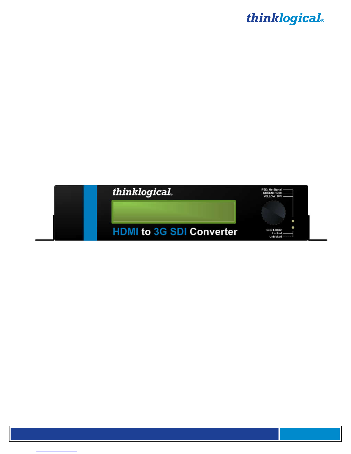
ront Panel Usage
The two front panel LED's will display the status of the applied
ste
The bottom LED will be off until a valid
steady green
thinklogical
thinklogicalthinklogical
thinklogical
HDMI to
The configured Input and Output settings are displayed
the display will read "
oder knob once will display the product description and the 7 different main menus as the knob is
turned. If the encoder is not pushed or turned in 20 seconds
More detailed information about using the Front Panel
r
t e r P r o d u c t M a n u a l , R e v . B
the desk and it can be conveniently mounted below the
SDI Converter chassis does not need to be opened or
desk mounting
No fan means that it
h sides of the unit (2”minimum)
18
HDMI input signal
is detected. It will
if a signal is present but
. If no signal is present at
" for both the Input and O
the screen will go back to the top level.
Appendix
Page
11
The HDMI to 3G
LCD dis
3G
®
RED: No Signal
GREEN: HDM I
YELLOW: DVI
®
encode knob and
3.4. Cooling
The HDMI to 3G
recommended that the ra
Note
For order of installation events,
4. General F
genlock signal.
• The top LED will be steady red
yellow for a DVI input and will be
•
not locked and it will be
GEN LOCK:
to 3G SDI Converter
Locked
Unlocked
ation.
our Quick Start Guide, Appendix B, page
if power is applied and no HDMI signal
ady green for an HDMI input.
genlock is applied. It will blink green
when in the locked condition.
Removable mounting
brackets installed for
under-desk mounting.
-
.
and the applied
be steady
3G SDI Converter, Front Panel
on the Front Panel LCD
the time of power up,
Not Configured
the enc
,
Display can be found in
Press and turn
the encoder knob
to navigate the
menus
utput. Pressing
D, page 23.
Page 12

H D M I t o 3 G S D I C o n v e
User Menu Configurations
SDI Converter has many configuration options
will cover these options in
Front Panel Display or Web Interface). Not all settings are
limitations.
: When performing a firmware upgrade
the factory default. (1080i @ 60
, hold the encoder knob in, apply power, then continue holding the knob in for 5
seconds. The LCD will read tha
through the ‘User Config’ menus in Appendix D, Main Menu E (page 29).
Regulatory & Safety Compliance
Symbols Found on Our Products
product
products comply with
Regulatory Compliance
products are designed and made in the U.S.A.
aboratory and found to be compliant with the following standards
(both domestic USA and many international locations).
These products comply with the following standards:
Edition (2003)
CAN/CSA C22.2 No. 60950
Electromagnetic Interference
FCC CFR47, Part 15, Clas
003 Issue 2, Revision 1
In a domestic environment this product may
in which case the user may be requi
Manufacturer’s Name & Address:
r
t e r P r o d u c t M a n u a l , R e v . B
Appendices
very configuration can be set regardless of
The unit’s default IP address is 192.168.75.200
it is recommended that the unit
One way to do this is, with power
t the factory default is being restored. Another way is
requirements.
roducts have been tested by a
cause radio interference,
®
Page
12
4.1
The HDMI to 3G
(page 23)
interface (e.g. RS-232,
Panel Display due to the display’s
Note
off
5.
5.1
Markings and labels on our
found on our
5.2
Thinklogical®
nationally recognized testing l
and
detail. E
Hz at 4:2:2 10-bit mode).
s follow industry-standard conventions.
domestic and many international
P
C (page 19) and D
the user
available on the Front
.
be restored to
Regulatory markings
North America
Safety
ANSI/UL60950-1: 1st
LASER Safety
CDRH 21CFR 1040.10
Class 1 LASER Product
Industry Canada ICES-
Australia & New Zealand
This is a Class A product.
European Union
Declaration of Conformity
-1-03
s A
red to take adequate measures.
Thinklogical, LLC®
100 Washington Street
Milford, Connecticut 06460 USA
Telephone: 1-203-647-8700
Page 13

H D M I t o 3 G S D I C o n v e
Product Name
HDMI to 3G SDI Converter, HDMI to 3G SDI Converter/Extender
These products comply with the requirements of the Low Voltage Directive 72/23/EEC and the
Standards with Which Our Products Comply
1, (2006)
IEC60825:2001 Parts 1 and 2
Electromagnetic Emissions
EN55022: 1994 (IEC/CSPIR22: 1993)
Electromagnetic Immunity
EN55024: 1998 Information Technology
2: 1995 Electro
3: 1996 Radiated Immunity Field Test
4: 1995 Electrical Fast Transient Test
5: 1995 Power Supply Surge Test
6: 1996 Conducted Immunit
8: 1993 Magnetic Field Test
11: 1994 Voltage Dips & Interrupts Test
Supplementary Information
The following statements may be appropriate for certain geographical regions and might not
digital apparatus meets all requirements of the Canadian Interference
Causing Equipment Regulations.
rique de la classe A respecte toutes les exigencies du R
rial brouilleur du Canada
is is a Class A product. In a domestic environment, this product may cause
radio interference, in which case the user may be required to take adequate corrective
has been tested and found to comply with the limits for a Class
digital device, pursuant to part 15 of the FCC Rules. These limits are designed to provide
reasonable protection against harmful interference when the equipment is operated in a
environment. This equipment generates, uses and can radiate radio
frequency energy and, if not installed and used in accordance with the instruction manual,
may cause harmful interference to radio communications in which case the user may be
take adequate corrective measures at their own expense.
r
t e r P r o d u c t M a n u a l , R e v . B
Immunity Characteristics
Page
13
Models:
EMC Directive 89/336/EEC.
5.3
Safety
CENELEC EN 60950-
LASER Safety
Class 1 LASER Product
EN61000-3-2/A14: 2000
EN61000-3-3: 1994
EN61000-4EN61000-4EN61000-4EN61000-4EN61000-4EN61000-4EN61000-4-
Equipment-
-Static Discharge Test
y Test
®
5.4.
apply to your location.
This Class A
Cet appareil numé
sur le maté
Warning! Th
measures.
Note: This equipment
commercial
required to
-
èglement
.
A
Page 14

H D M I t o 3 G S D I C o n v e
digital apparatus complies with Canadian ICES
verified as being compliant within the Class
Rules (FCC Title 47, Part 15
methods of measurement of Radio Disturbance Characteristics of Information Technology
The user may notice degraded audio performance in the presence of
If using a keyboard that is noise susceptible, a ferrite
may be needed to comply with Immunity Requirements
Product Serial Number
cts have a unique serial number
the bottom of the chassis. The serial number includes a da
digits for the year,
This serial number is also found on the
Connection to the Product
Connections and installation hardware for
All wiring connections to the customer equipment
proprietary or customized conne
appropriate power cords and approved methods.
Support
Customer Support
is an engineering company and you will receive any information you
m our most knowledgeable engineers. We believe that the first lines of
support are design engineers that developed each particular product. Therefore, your
questions will be handled promptly by our in
Thank you for choosing Thinklogical
We appreciate your business and are dedicated to helping you successfully use our products
please use the following telephone numbers and internet
Check out our website for current product offerings, support information and general information
we offer.
Our internet website offers product information on all current systems, inc
specification sheets and installation guides (for viewing online or for download), product
diagrams showing physical connections and oth
r
t e r P r o d u c t M a n u a l , R e v . B
limits of the FCC Radio Frequency Device
, Subpart B CLASS 1), measured to CISPR 22: 1993 limits and
on the keyboard
n adhesive
code. The format for the date
two or three digits for a unique unit number.
standard devices and
are designed
Power connections are made with regionally
house engineers who are most familiar with
products for your application
is always here to help you
-
er information you might need.
®
Page
14
Note: This Class A
Equipment.
Note:
electromagnetic fields
Note:
5.4.1.
Thinklogical® produ
is 2 digits for the week, 2
5.4.2.
methods.
.
original shipping carton.
ctors and cabling.
A
ring
printed on a
te-
plus
our products use industry-
-003 and has been
cable
label that is fixed to
-code
to minimize
6 Thinklogical®
6.1.
Thinklogical®
require directly fro
your products.
To contact us,
6.1.1. Website
about all of the products
-
®
®
.
based methods:
luding technical
.
.
Page 15

H D M I t o 3 G S D I C o n v e
Internet:
www.thinklogical.com
Most online documents are stored as Adobe Acrobat “PDF” files. If you do
not have the Adobe Acrobat reader needed to view PDF files, visit
is staffed Monday through Friday from
to respond to your email inquiries promptly
Information on
Sales Department
Product support, technical issues or questi
repairs and request for Return Authorization.
Telephone
ontact our expert sales staff in Milford, CT at
free number 1
0am to 5:00pm, Eastern Time Zone. Ask
Contact Produ
support lines are manned Monday through Friday,
Please contact our U
through Friday, 8:30am to 5:0
City). If leaving a voice message, please provide a
Our switchboard attendant will direct your call during regular bu
automated attendant answering our main telephone switchboard after regular business hours
leave voice messages for individuals at any time. Our Sales
Representatives have direct numbers to
Our company facsimile number is
your cover sheet and provide return contact information.
Product Support
support personnel are available Monday throu
Eastern Time Zone. If your application might require assistance at some time outside of our
normal business hours, please contact us beforehand and we will do our best to make
arrangements to help you with your
warrants this product against defects in materials and workmanship for a period of
one year from the date of delivery.
r
t e r P r o d u c t M a n u a l , R e v . B
, Eastern Time Zone.
use
orders, questions or issues.
ons, product
647
. We are her
for
1
pm, Eastern Time Zone.
1
0pm, Eastern Time Zone (same as New York
time to call back so we may reach
siness hours. We have an
. Please indicate the nature of the fax on
gh Friday from 8:30am
and its suppliers disclaim any and all other
Page
15
Note:
for a download.
6.1.2. Email
®
www.adobe.com
Thinklogical®
We will do our best
email addresses:
info@thinklogical.com –
sales@thinklogical.com –
support@thinklogical.com –
6.1.3.
Sales: Please c
continental U.S., use our toll-
Friday from 8:3
number when you call.
Product Support:
International Sales:
are here Monday
you at your convenience.
8:30am to 5:00pm
. Please
Thinklogical® and our products.
-
1-203-
-800-291-3211
a sales rep
ct Support in Milford, Connecticut at
8:30am to 5:00
.S. sales staff in Milford, CT at
preferred
one of the following
-8700 or, if in the
e Monday through
a direct dial phone
-203-647-8700. The
-203-647-8700. We
and holidays. You may
facilitate your next call to us.
6.1.4. Fax
1-203-783-9949
6.2
Thinklogical’s®
Thinklogical® products.
6.2.1. Warranty
Thinklogical®
Thinklogical®
warranties.
to 5:00pm,
Page 16

H D M I t o 3 G S D I C o n v e
Note: Thinklogical®
Inc. products carry a one year warranty, with longer term
available at time of purchase on most products. Please refer to your product invoice
for your products Warranty Terms & Conditions.
remedy shall be, repair or replacement of the product, pr
returned to the authorized dealer within a year from the date of delivery.
If you wish to return your device, contact the
purchased the device, or if you purchased directly, cal
Return Authorization
any Thinklogical
Thinklogical
8700
Thinklogical
the problem and will issue you a
al box, if possible, and return it with the RMA# on the box.
Do not return a product to Thinklogical
for products with Return Material Authorization
3211 (USA only)
r
t e r P r o d u c t M a n u a l , R e v . B
ovided that the defective
authorized dealer where you
800
product, have product questions or need technical
Customer Support
Customer Support will ask you to describe
number
Return Material
Page
16
Defect
product is
Thinklogical®
l Thinklogical at 1-
-291-3211 (USA).
®
6.2.2.
If you have any issue with
assistance with your
3211 (USA only) or 1-203-647-
If you must return a product to
Pack the device in its origin
Note:
Authorization Number.
Return address
Thinklogical, LLC®
Attn: RMA#
100 Washington Street
Milford, CT 06460 USA
PH: 800-291-
system, please contact
and let us help.
®
directly,
Return Merchandise Authorization
®
without a
:
at 1-800-291-
(RMA#).
Page 17

H D M I t o 3 G S D I C o n v e
r
t e r P r o d u c t M a n u a l , R e v . B
Page
17
APPENDIX A: HDMI to 3G SDI Application Drawings
Network
Hub
C
u
s
S
t
u
o
C
p
m
o
p
m
e
l
i
r
e
p
d
u
t
e
r
Velocitydvi-3
Receiver
F
i
b
e
r
O
p
t
i
c
C
a
b
l
e
R
S
-
2
3
SDI
Source
S
Local
HDMI
Display
D
I
I
N
HDMI OUT
2
F
e
l
b
a
C
c
i
t
p
O
r
e
b
i
3G SDI to HDMI
Converter
HDX80 Router
S
D
I
G
e
n
L
o
c
T
U
O
I
D
S
HDMI to 3G SDI
Converter
M
o
n
i
t
o
r
k
I
N
DVI to
HDMI cable
Thinklogical conversion application using a 3G SDI to HDMI Converter with fiber extension, VX80
Router, 3 AV+ Receiver and HDMI to 3G SDI Converter
C
u
s
S
t
u
o
C
p
m
o
p
m
e
l
i
r
e
p
d
u
t
e
r
s
e
l
b
a
C
c
i
t
p
O
r
e
b
i
F
R
S
-
4
2
2
R
S
-
2
3
2
M
D
H
F
N
I
I
V
D
/
I
S
s
e
l
b
a
C
c
i
t
p
O
r
e
b
i
N
I
I
D
S
D
I
M
o
n
i
t
o
r
H
D
M
S
D
I
O
U
T
H
I
M
o
n
i
t
o
r
T
U
O
I
M
D
R
S
-
4
2
2
Thinklogical conversion application using an HDMI to 3G SDI Converter with fiber output, HDX80 Router,
SDI 3G+ Receiver and 3G SDI to HDMI Converter
Page 18

H D M I t o 3 G S D I C o n v e
r
t e r P r o d u c t M a n u a l , R e v . B
Page
18
APPENDIX B: HDMI to 3G SDI Converter Quick Start Guide
Page 19

H D M I t o 3 G S D I C o n v e
APPENDIX C: GUI
The graphical user interface (GUI) for the
create, set, and recall custom configurations. There are 6 main menus that allow you to
Input/Output, Video Processor, Audio, User Configurations,
menus under the video processor menu for
When power has been cycled on a unit it will res
Power On Config” has been set in the User Menu.
This menu allows you to select the input and the format of the output. There is also an option to select
tput as well as Enable Genlock.
output format
r
t e r P r o d u c t M a n u a l , R e v . B
was developed for ease of use to
and
Picture C
et to factory settings unless the “Set
By clicking the “Take” button at the bottom of the screen you
Page
19
There are sub-
HDMI to 3G SDI Converter
Xtreme 3G
Video Control and
®
configure the
System Information.
ontrol.
Note:
Input/Output Menu
the 3D ou
are able to commit the
that you have selected.
Page 20

H D M I t o 3 G S D I C o n v e
r
t e r P r o d u c t M a n u a l , R e v . B
Page
20
Video Processor > Video Control
The video control sub-menu allows you to control De-Interlacer, Noise Reducer, Compression Artifact
Reducer, Edge Enhancer, and Adaptive Contrast Enhancer.
Video Processor > Picture Control
The picture control sub-menu allows you to control Hue Saturation, Advanced Color Remapping, Flesh
Tone Correction and Color Temperature. You can also reset all levels back to the factory default.
Page 21

H D M I t o 3 G S D I C o n v e
r
t e r P r o d u c t M a n u a l , R e v . B
Page
21
Audio
The audio menu allows you to select which output audio channel is sourced with any input audio
channel. It also allows you to enter an audio delay (from -50 ms to +50 ms) when needed.
User
The user menu allows you to save your current configuration by name or restore factory configuration.
You can also use the drop down menu to “Select Config Name” and set power on configuration (which
sets the current configuration to be the default power on configuration), restore factory configuration and
delete the selected configuration.
Page 22

H D M I t o 3 G S D I C o n v e
r
t e r P r o d u c t M a n u a l , R e v . B
Page
22
Xtreme 3G
The Xtreme 3G menu is valid only if the Xtreme 3G+Extension Option is installed. This menu allows you
to view the Xtreme 3G Module and 3G SFP information of the unit in use. From this menu, you can also
change the communication behavior of the RS-422 by selecting “Toggle DCE/DTE”.
System Info
The system info menu allows you to view information for the inputs and outputs as well as Genlock and
software and firmware versions.
Page 23

H D M I t o 3 G S D I C o n v e
r
t e r P r o d u c t M a n u a l , R e v . B
Page
23
APPENDIX D: Front Panel Display and RS-232
Front Panel Display
The front panel menus can be navigated by using the encoder knob, located on the right side of the
front panel. The encoder knob is an easy way to quickly configure the unit without the need for any other
communication interfaces. The encode knob is used to cycle through the different configuration/settings
menus. Pressing the encoder knob will either enter into a new, lower-layered menu or commit the current
selection.
The configured Input and Output settings are displayed on the Front Panel LCD. If no signal is present at
the time of power up, the display will read "Not Configured" for both the Input and Output. Pressing the
encoder knob once will display the product description and the 7 different main menus as the
knob is turned. If the encoder is not pushed or turned in 20 seconds, the screen will go back to the top
level.
Most commands will have a confirmation message displayed that shows acknowledgement of the
command. Due to the limited amount of data that can be displayed via the LCD, not all detailed data can
be displayed. It is suggested to either use the RS-232 or Ethernet interface for such queries.
Press and turn
the encoder knob
to navigate the
menus
Front panel LCD and encode knob
RS-232 Interface
The RS-232 and RS-422 interface menus have an 'exit' option. Selecting this option will display the
menu items one level higher. The SPACE bar will repeat the current menu and the ENTER key will
return the user to the top level menu. The following menus are formatted similarly to the configuration
menus displayed on power-up.
The RS-232 setup and configuration is as follows:
•
Use Hyperterm or similar type interface.
•
Baud rate is 115200, 8 bits, no parity, 1 stop bit, no flow control
•
Emulate VT-100 mode
MAIN USER MENU:
A: Set Input Select
B: Set Output Select
C: Video Processing Setup
D: Audio Info and Setup
E: User Config Setups
F: System Settings
G: System Information
Note:
A valid input must be applied in order for the configuration to be used.
Page 24

H D M I t o 3 G S D I C o n v e
r
t e r P r o d u c t M a n u a l , R e v . B
Page
24
MAIN MENU A: Set Input Select
a: AUTO mode ON
Detects when a video source has changed format. On cable insertion, the unit performs a re-
configuration of the last known output setting with the new input. This is the default mode.
b: AUTO Mode OFF
Turns off the AUTO mode.
MAIN MENU B: Set Output Select
Selects the output format of the SDI video. Default is 1080i @ 60
a: Standard Def. Output
Selects the menu for Standard Definition video output format.
SUB-MENU a: Standard Def. Output
Selects a SD output format type of the selected resolutions:
b: High Definition Output
Selects the menu for High Definition video output format.
SUB-MENU b: High Definition Output
Selects a HD output format type of the selected resolutions:
a: 480i @ 59.94 (525-270)
b: 576i @ 50 (625–270)
a: 720p @ 23.97
b: 720p @ 24
c: 720p @ 25
d: 720p @ 29.97
e: 720p @ 30
f: 720p @ 50
g: 720p @ 59.94
h: 720p @ 60
i: 1035i @ 59.94
j: 1035i @ 60
k: 1080i @ 50
l: 1080i @ 59.94
m: 1080i @ 60
n: 1080p @ 23.97
o: 1080p @ 24
p: 1080p @ 25
q: 1080p @ 29.97
r: 1080p @ 30
s: 1080psf @ 23.97
t: 1080psf @ 24
u: 1080psf @ 25
v: 1080psf @ 29.97
w: 1080psf @ 30
Note: All HD outputs are 10 bit YCbCr 4:2:2
c: 3G Level A Output
Selects the menu for 3G Level A video output format.
SUB-MENU c: 3G Level A Output
Page 25

H D M I t o 3 G S D I C o n v e
r
t e r P r o d u c t M a n u a l , R e v . B
Page
25
Selects a 3G Level A output format type of the selected resolutions:
a: 1080i @ 50
b: 1080i @ 59.94
c: 1080i @ 60
d: 1080p @ 23.97
e: 1080p @ 24
f: 1080p @ 25
g: 1080p @ 29.97
h: 1080p @ 30
i: 1080p @ 50 4:2:2 10b
j: 1080p @ 59.94 4:2:2 10b
k: 1080p @ 60 4:2:2 10b
l: 1080sf @ 23.97
m: 1080sf @ 24
n: 1080sf @ 25
o: 1080sf @ 29.97
p: 1080sf @ 30
1080p50, 1080p59.94, and 180p60 can only be YCbCr 4:2:2 10 bit. All other resolutions will proceed to
a sub-menu for color space and bit width selection.
d: 3G Level B Output
Selects the menu for 3G Level B video output format.
SUB-MENU d: 3G Level B Output
Selects a 3G Level B output format type of the selected resolutions:
a: 1080i @ 50
b: 1080i @ 59.94
c: 1080i @ 60
d: 1080p @ 23.97
e: 1080p @ 24
f: 1080p @ 25
g: 1080p @ 29.97
h: 1080p @ 30
i: 1080p @ 50 4:2:2 10b
j: 1080p @ 59.94 4:2:2 10b
k: 1080p @ 60 4:2:2 10b
l: 1080sf @ 23.97
m: 1080sf @ 24
n: 1080sf @ 25
o: 1080sf @ 29.97
p: 1080sf @ 30
1080p50, 1080p59.94, and 1080p60 can only be YCbCr 4:2:2 10 bit. All other resolutions will proceed to
a sub-menu for color space and bit width selection.
Menu after 3GA/3GB resolution selection:
Output DL/3G Color Space/Bits Menu
Selects the output color space (YCbCr or RGB) and the bit width (10 or 12 bits):
a: YCbCr 4:4:4 10b
b: YCbCr 4:4:4 10b
c: YCbCr 4:4:4 10b
d: RGB 4:4:4 10b
e: RGB 4:4:4 10b
Page 26

H D M I t o 3 G S D I C o n v e
r
t e r P r o d u c t M a n u a l , R e v . B
Page
26
MAIN MENU C: Video Processing Setup
a: Comp. Artifact Reducer
Selects the menu for Component Artifact Reducer (CAR) video processing functions.
SUB-MENU a: Comp. Artifact Reducer
This feature is used to reduce compression artifacts that are caused by video compression
schemes such as MPEG2. Mostly used on YCbCr 4:2:2 interlaced or progressive input video.
a: Comp. Arti. Reducer EN
Enables the Compression Artifact Reducer.
b: Mosq. Noise Reducer EN
Enables the Mosquito (Ringing) Noise Reducer.
c: Block Noise Reducer EN
Enables the Block (8x8) Noise Reducer.
d: Non Std Block Noise Det EN
Enables the Non-Standard Block Detection.
e: Enable All CAR Blocks
Enables All the above (A,B,C,D) Noise Reduction Blocks.
f: Disable All CAR Blocks
Disables All the Noise Reduction Blocks.
b: DeInterlacer
Selects the menus for the DeInterlacer (DEINT) video processing functions.
SUB-MENU b: DeInterlacer
Selects the menu for the DeInterlacer (DEINT) video processing functions.
a: Deinterlacer BYPASS
Bypasses the deinterlacer (input is progressive).
b: Deint 2D VECTOR
Sets the Interlacer for 2D Vector mode (Interlaced input DEFAULT mode).
c: Deint 2D VECTOR AGGRES.
Sets the Interlacer for 2D Aggressive mode (Interlaced input).
d: Deinterlacer DEFAULT
Sets the Interlacer for DEFAULT mode.
c: Noise Reducer
Selects the menus for the Noise Reduction (NR) video processing functions.
SUB-MENU c: Noise Reducer
Selects the menus for the Video Noise Reduction (NR) video processing functions. Used
mostly on YCbCr 4:2:2 Input video.
a: Noise Reducer DISABLE
Disables the Noise Reduction block.
b: Noise Reducer 2D
Sets the Noise Reducer for 2D (Spatial) mode.
c: Noise Reducer 3D Fixed
Sets the Noise Reducer for 3D Fixed (Temporal) mode.
d: Noise Reducer 3D Adapt
Sets the Noise Reducer for 3D Adaptive (Temporal) mode.
e: Noise Reducer Default
Sets the Noise Reducer for Default mode.
f: Noise Reducer Automatic
Sets the Noise Reducer for Automatic mode.
Page 27

H D M I t o 3 G S D I C o n v e
r
t e r P r o d u c t M a n u a l , R e v . B
Page
27
d: Picture Control
Selects the menus for Picture Control (PC) video processing functions.
SUB-MENU d: Picture Control
a: Set All Levels Default
Restores Contrast, Brightness, Tint, Black, Color Temp levels to defaults.
b: Set Contrast Level
Enter the Contrast Level 0 to +10. The Default value is 10.
c: Set Brightness Level
Enter the Brightness Level -100 to +100. The Default value is 0.
d: Set Tint Level
Enter the Tint Level -180 to +180. The Default value is 5.
e: Set Black Level
Enter the Black Level 0 to +100. The Default value is 0.
f: Set Color Temperature
SUB MENU f: Video Set Color Temperature Menu
a: Color Temperature NORMAL
Sets the color temp to 6500.
b: Set Color Temperature COOL
Sets the color temp to 8000.
c: Color Temperature WARM
Sets the color temp to 6000.
d: Color Temperature CUSTOM
Enter Color Temp Level 6000 to 8000 (Normal = 6500)
e: Edge Enhancer
Selects the menus for Edge Enhancement (EE) video processing functions.
SUB-MENU e: Edge Enhancer
Selects the menus for Edge Enhancement (EE) video processing functions.
a: Edge Enhancer OFF
b: Edge Enhancer LOW
c: Edge Enhancer MED
d: Edge Enhancer HIGH
f: Color Management Unit
Selects the menus for Color Management Unit (CMU) video processing functions.
SUB-MENU f: Color Management Unit
Selects the menus for Color Management Unit (CMU) video processing functions.
a: Hue Saturation Menu
a: Hue Saturation ENABLE
b: Hue Saturation DISABLE
c: Intelligent Saturation ENABLE
d: Intelligent Saturation DISABLE
e: Set HUE Saturation Level
f: Set HUE Global Sat. Level
g: ICR Advanced Menu
Note: Hue saturation must be enabled (selection ‘a’) in order for ‘Set HUE Saturation Level’
(selection ‘e’) to be valid.
b: Qdeo True Color Menu
a: Qdeo True Color OFF
Page 28

H D M I t o 3 G S D I C o n v e
r
t e r P r o d u c t M a n u a l , R e v . B
Page
28
b: Qdeo True Color SOFT
c: Qdeo True Color GENTILE
d: Qdeo True Color MEDIUM
e: Qdeo True Color HIGH
c: Film Grain Gain Menu
a: Disable Film Grain Gain
b: Set Film Grain Gain
Range is 0 - 255. Default is 0.
c: Set FGG Temporal Freq.
Range is 0 - 255. Default is 0.
d: Flesh Tone Correction
a: Set FTDC Preset Enable
b: Set FTDC Preset Level 1
c: Set FTDC Preset Level 2
d: Set FTDC Preset Level 3
e: Set FTDC Preset Level 4
f: Set FTDC Preset Level 5
g: Set FTDC Preset Level 6
h: Set FTDC Preset Disable
e: Set GAMMA Menu
a: GAMMA Disable
b: GAMMA 1.8
c: GAMMA 2.5
d: GAMMA S-Curve Light
e: GAMMA S-Curve Dark
g: Adapt. Contrast Enhancer
Selects the menus for the Adaptive Contrast Enhancer (ACE) video processing functions.
SUB-MENU g: Adapt. Contrast Enhancer
Selects the menus for the Adaptive Contrast Enhancer (ACE) video processing functions.
a: ACE PRESET OFF
b: ACE PRESET LOW
c: ACE PRESET MEDIUM
d: ACE PRESET HIGH
e: ACE PRESET RANGE 0-255
f: ACE PRESET RANGE 16-235
g: ACE Brightness Menu
a: Brightness DISABLE
b: Brightness DEFAULT
c: Brightness Taper Size
Enter Taper Size (16, 32, 64, 128, 256, 512).
d: Brightness Taper Side
Enter Taper Side Select (1,2).
e: Brightness Enhancement
Enter Enhancement Level (1-15).
f: Brightness Threshold 1
Enter Threshold 1 Level (0-1023).
g: Brightness Threshold 2
Enter Threshold 2 Level (0-1023).
MAIN MENU D: Audio Info and Setup
a: Enable Audio Output
Page 29

H D M I t o 3 G S D I C o n v e
r
t e r P r o d u c t M a n u a l , R e v . B
Page
29
Enables the embedded audio output from the selected input.
b: Disable Audio Output
Mutes all embedded audio output channels.
c: Audio Source Menu
Menu to select either embedded audio, balanced audio, or AES/EBU audio.
d: Get Audio Input Info
Displays Information about the Input audio.
e: Set Audio Delay
Audio Delay range is from -50 - +50 in mS with the default being 0.
f: Get Audio Delay
The programmed Audio Delay in mS.
g: Get Audio Channel Cfg.
Get the audio channel mapping.
h: Assign Audio Channels
Configure input to output channel configuration.
i: Swap Audio Left/Right
Swap the left and right channels on any of the four enbedded audio groups.
j: Get Audio Left/Right Swap
Displays the swap status of the 4 embedded audio groups.
k: Set Analog Audio Gain
Adjust the gain on the balanced audio pair for left and right channels.
l: Get Analog Audio Gain
Displays the gain of the left and right channels.
MAIN MENU E: User Config Setups
a: Save Current Config
Saves the current system settings to the non-volatile Memory. Maximum of 20 characters for the
record name.
b: Set Power On Config
This option will set the current configuration to the user in an accessible region of flash. This
configuration is restored during power up.
c: Restore Config Record
Recall any one of the current saved configuration records.
d: Restore Factory Config
By selecting this, the HDMI to 3G SDI Converter will delete the stored power on configuration.
Configuration and will re-configure to the factory default on the next power cycle (1080i @ 60 Hz).
e: Erase Record(s)
Erase a particular record or all records.
MAIN MENU F: System Settings
a: Enable Genlock
Enables the Genlock feature (Valid signal needs to be applied).
b: Disable Genlock
Disables Genlock. Genlock needs to be disabled before changing output settings.
c: Ethernet Settings
Settings for the network interface.
Default Settings:
IP Address - 192.168.75.200
Mask - 255.255.255.0
Gateway - 0.0.0.0
Page 30

H D M I t o 3 G S D I C o n v e
Note: To change the IP address of a device: From the SYSTEM MENU, go to ETHERNET
SETTINGS, then to SET IP ADDRESS.
Changes the communication behavior of the RS422 (Valid only if EXtreme 3G+ option is installed
MAIN MENU G: System Information
The following is used for retrieving information regarding current setup and signal detection
The 'Get Input Info', 'Get Output Info' will display the signal format only on the Front Panel whereas the
other communications interfaces will display more verbose information.
Displays the System’s software version
version number
Displays the version of software running on the Ethernet device.
Displays the temperature inside the box
the video and embedded audio signal on BNC Input.
Displays Information about the video and embedded audio signal on SDI Output.
Displays Information about the Genlock status.
tion about the
Ordering Information
3G
3G
SDI Conv
ics Package Mulit
HDC Optics Package Single
r
t e r P r o d u c t M a n u a l , R e v . B
Page
30
d: Front Panel Contrast Setting
Adjusts the LCD contrast.
e: Toggle RS422 DCE/DTE
®
).
information.
a: Get Software Version
b: Get FPGA Version
Displays FPGA
c: Get LINUX Version
d: Get Local Temperature
e: Get Input Info
Displays Information about
f: Get Output Info
g: Get Genlock Info
h: Get Xtreme 3G Info
Displays Informa
APPENDIX E:
HDC-000001 HDMI to
HDC-000001-LC HDMI to
Optics for HDMI to 3G
VOP-M19 HDC Opt
VOP-S04
Our address:
number
Xtreme 3G transmit card (If installed).
SDI Converter
SDI Converter/Extender
erter with Xtreme 3G+ Extension
-Mode, LC
-Mode, LC
Thinklogical, LLC®
100 Washington Street
Milford, CT 06460 USA
Sales: 1-203-647-8700
Fax: 1-203-783-9949
 Loading...