

Page 1
MAN-000018 REVISION A
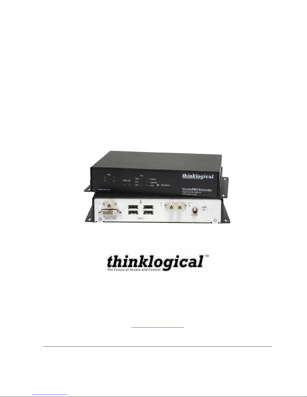
DCS StudioPRO
USB and Video Extender
Product Manual
Thinklogical Inc.
100 Washington Street
Milford, Connecticut 06460 U.S.A.
Telephone (203) 647-8700
Fax (203) 783-9949
www.thinklogical.com
Page 2

Page 3

MAN-000018 i REVISION A
Copyright Notice
Copyright © 2007 All rights reserved. Printed in the U.S.A.
Thinklogical, a subsidiary of Logical Solutions, Incorporated
100 Washington Street
Milford, Connecticut 06460 U.S.A.
Telephone (203) 647-8700
All trademarks and service marks are property of their respective owners.
Document ID: MAN-000018
Subject: DCS StudioPRO USB and Video Extender
Revision: Rev A, August 2007
Page 4

MAN-000018 ii REVISION A
Table of Contents
1. Introduction ...................................................................................................................................... 1
1.1. Intended Application ................................................................................................................. 1
1.2. Increased Security and Efficiency............................................................................................. 1
1.3. Laser Information...................................................................................................................... 2
2. System Features .............................................................................................................................. 3
2.1. General System Features......................................................................................................... 3
2.2. Hardware Features................................................................................................................... 3
2.2.1. Transmitter ........................................................................................................................... 4
2.2.2. Receiver ............................................................................................................................... 4
2.3. Technical Specifications ........................................................................................................... 5
3. Connecting the SPE System ........................................................................................................ 7
3.1. Overview .................................................................................................................................. 7
3.2. Contents................................................................................................................................... 8
3.3. Order of Installation Events ...................................................................................................... 8
3.3.1. Fiber Optic Cables ............................................................................................................ 9
3.3.6. AC Power Supply – PWR-000022-R (Quantity 2) ........................................................... 11
3.4. LED Status ............................................................................................................................. 12
3.4.1. Transmitter ..................................................................................................................... 12
3.4.2. Receiver ......................................................................................................................... 12
3.5. General Button Usage – DDC Select...................................................................................... 13
3.5.1. Operation of the Thinklogical DDC Modes ...................................................................... 13
4. Regulatory and Safety.................................................................................................................... 15
4.1. Safety Requirements .............................................................................................................. 15
4.1.1. Symbols Found on Product............................................................................................. 15
4.1.2. Product Serial Number.................................................................................................... 15
4.1.3. Connection to the Product............................................................................................... 15
4.2. Regulatory Compliance .......................................................................................................... 15
4.3. North America ........................................................................................................................ 16
4.4. Australia & New Zealand ........................................................................................................ 16
4.5. European Union ..................................................................................................................... 16
4.5.1. Declaration of Conformity................................................................................................ 16
4.5.2. Standards With Which the Products Comply................................................................... 17
4.6. Supplementary Information..................................................................................................... 17
5. How to Contact Us ......................................................................................................................... 19
5.1. Customer Support .................................................................................................................. 19
5.1.1. Website........................................................................................................................... 19
5.1.2. Email .............................................................................................................................. 19
5.1.3. Telephone....................................................................................................................... 19
5.1.4. Fax ................................................................................................................................. 20
5.2. Product Support...................................................................................................................... 20
5.2.1. Warranty ......................................................................................................................... 20
5.2.2. Return Authorization ....................................................................................................... 20
5.2.3. Our Address ................................................................................................................... 20
Page 5

MAN-000018 iii REVISION A
Appendix A Ordering Information...................................................................................................... 21
A.1 StudioPRO Extenders ............................................................................................................ 21
A.2 Related Products - DCS StudioPRO Matrix Switch................................................................. 21
Appendix B Enclosure Dimensions ........................................................................................................ 22
Page 6

Page 7
MAN-000018 1 REVISION A
1. Introduction
1.1. Intended Application
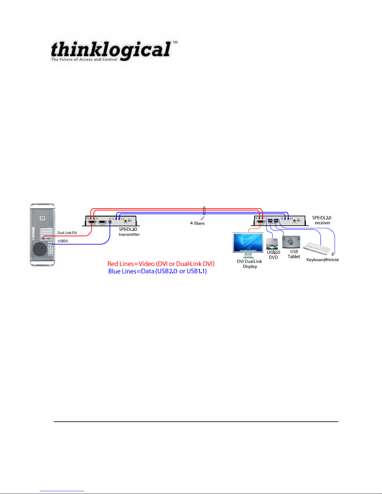
The StudioPRO Extender (SPE) is a fiber optic extender designed to extend USB 1.1 or USB 2.0 and
DVI video signals up to 1000 meters (3280 feet) over standard duplex multimode fiber. With the SPE, all
USB 1.1 or USB 2.0 peripherals can be conveniently located while operating at optimal speed.
Comprised of two compact units, the SPE transmitter connects to the host computer with standard USB
and DVI cables and the receiver provides four ports for connection of peripheral devices as well as video
connections. External power is required for both the transmitter and receiver units and two universal
power supplies are included. Plug-and-play with no adjustments makes setting up the SPE fast and
easy. In addition, LEDs provide link performance at a glance. The SPE successfully and effectively
delivers USB peripherals when and where you need them.
Figure 1: Intended Application of StudioPRO Extender, Dual Link USB 2.0 model shown
1.2. Increased Security and Efficiency
The ability to remote the CPU away from the monitor allows more control of the computer environment.
Now it is possible to position the monitor or projector in any setting from office to lecture hall to
boardroom while keeping the computer secure in a remote, controlled location.
Page 8

MAN-000018 2 REVISION A
1.3. Laser Information
LASER RADIATION
DO NOT VIEW DIRECTLY WITH OPTICAL
INSTRUMENTS
CAUTION: In order to avoid possible exposure to laser energy, it is good practice to attach the fiber optic
cables prior to applying power to the StudioPRO EXTENDER. If the fiber optic cable should become
disconnected, DO NOT attempt to look into the cable or the panel mounted connector.
The StudioPRO Extender is designed and identified as a Class 1M LASER product.
Page 9

MAN-000018 3 REVISION A
2. System Features
2.1. General System Features
The SPE systems are designed for high-resolution video and USB extension applications, such as
remote projection centers, theaters and assembly halls, and for secure computer installations. The ability
to remotely locate the CPU away from the monitor and peripherals allow more control of your computer
environment. It is possible to position the monitor or projector in any setting from office to lecture hall to
boardroom while keeping the computer secure in a remote, controlled location.
Extends Hi-Speed USB 1.1 connection up to 3280 feet (1000 meters)
Four port Class A device
Installation is Plug-and-Play, no adjustments are necessary
Supports USB 1.1 low-speed /full-speed and USB 2.0 hi-speed devices
Uses standard duplex multi-mode fiber optic cable
LEDs provide link performance status
Available with your choice of ST or SC fiber connectors
Supports video resolutions up to 2048x2560 in a dual-link
Support of the DVI-D interface
Fully DDC2B compliant
Transparent operation and functionality - no user interaction required
Signal transmission via fiber optic cable - no RF interference
2.2. Hardware Features
The SPE systems are self-contained and do not require user modifications. Once installed, the
application simply delivers the video and USB signal clearly and consistently.
Enclosed metal chassis for each Transmitter and Receiver unit
One pair of components per video connection
One DVI-D port for digital video signal connection
External power jack
Two universal AC power Adapters provided with each SPE System
Page 10

MAN-000018 4 REVISION A
2.2.1. Transmitter
Figure 2: Front and Back Views of the SPE Transmitter Models
2.2.2. Receiver
Figure 3: Front and Back Views of the SPE Receiver Models
Page 11

MAN-000018 5 REVISION A
2.3. Technical Specifications
Each Logical Solutions StudioPRO Extender system is designed to the following specifications:
Electrical Cable
(supplied with system)
USB Type A to USB Type B Cable, 6FT
DVI-I Male to DVI-D Male Cable, 2M (Single Link Model Only)
DVI-D Male to DVI-D Male Dual-Link Cable, 2M (Dual Link Model Only)
Connectors Single-Link Receiver:
DVI-D female video input (1)
Fiber connectors-data (2)
Fiber connectors-video (1)
USB-A connectors (4)
Power connector (AC adapter provided and required) (1)
Dual-Link Receiver:
DVI-D female video input (1)
Fiber connector-data (2)
Fiber connectors-video (2)
USB-A connectors (4)
Power connector (AC adapter provided and required) (1)
Single-Link Transmitter:
DVI-D female video output (2)
Fiber connectors-data (2)
Fiber connectors-video (1)
USB-B connectors (1)
Power connector (AC adapter provided and required) (1)
Dual-Link Transmitter:
DVI-D female video output (2)
Fiber connectors-data (2)
Fiber connectors-video (2)
USB-B connectors (1)
Power connector (AC adapter provided and required) (1)
DDC Protocol
Full DDC2B compliant
Optical Budget
7 dB
Laser Output
Specifications
Video Lasers meet Laser Class 1M Specifications
USB laser meets Laser Class 1 Specifications.
Page 12

MAN-000018 6 REVISION A
Optical Cable Single-Link:
Two fibers for USB; Single fiber for video
Dual-Link:
Two fibers for USB; Two fibers for video
All Fiber is multi-mode, 50 micron or 62.5 micron. (Fiber Cable is either
customer-supplied or can be ordered from Thinklogical.)
Operating Temperature
and Humidity
0 to 50 °C (32 to 122 °F), 5 to 95% RH, non-condensing
Housing Dimensions
(includes rack ears)
1.64 in x 7.97 in x 5.08 in
(4.2 cm x 20.2 cm x 12.9 cm)
Wall-mount keyhole slot spacing: 8.469 in x 3.987 in
(21.5 cm x 10.1 cm)
Supply Voltage
+5.0 VDC @ 600 mA
Page 13

MAN-000018 7 REVISION A
3. Connecting the SPE System
3.1. Overview
5VDC
L3 L4
L1TL2
R
USB2.0
DVILOCALDISPLAY
DUALLINK
DVIFROMCPU
DUALLINK
POWER
5VDC
L3L4 L1RL2
T
POWER
USB2.0DVITODISPLAY
DUALLINK
5VDC
L3 L4
L1TL2
R
USB1.1
DVILOCALDISPLAY
DUALLINK
DVIFROMCPU
DUALLINK
POWER
5VDC
L3 L1TL2
R
USB1.1
DVILOCAL DISPLA Y
SINGLELINK
DVIFROM CPU
SINGLELINK
POWER
5VDC
L3L4 L1RL2
T
POWER
USB1.1DVITO DISPLAY
DUALLINK
USB1.1
5VDC
L3
L1
R
L2
T
POWER
DVITO DISPLA Y
SINGLELINK
5VDC
L3 L1TL2
R
USB2.0
DVILOCAL DIS PLAY
SINGLELINK
DVIFROM CPU
SINGLELINK
POWER
USB2.0
5VDC
L3
L1
R
L2
T
POWER
DVITO DISPLAY
SINGLELINK
Single Link DVI
USB2.0
3 fibers
SPE-SL2.0
transmitter
SPE-SL2.0
receiver
DVI single link
Display
USB2.0
DVD
Keyboard/mouse
USB
Tablet
Dual- Link DVI
USB2.0
4 fibers
SPE-DL2.0
transmitter
SPE-DL2.0
receiver
DVI Dual- Link
Display
USB2.0
DVD
Keyboard/mouse
USB
Tablet
Single Link DVI
USB1.1
3 fibers
SPE-SL1.1
transmitter
SPE-SL1.1
receiver
DVI single link
Display
USB1.1
Drive
Keyboard/mouse
USB
Tablet
Dual- Link DVI
USB1.1
4 fibers
SPE-DL1.1
transmitter
SPE-DL1.1
receiver
DVI Dual- Link
Display
USB1.1
Drive
Keyboard/mouse
USB
Tablet
Red Lines= Video( DVI or Dual- Link DVI)
Blue Lines= Data( USB2. 0 or USB1.1)
StudioPRO Extender Connection Diagrams
Figure 4: SPE Connections by Model
Page 14

MAN-000018 8 REVISION A
3.2. Contents
When you receive your Thinklogical StudioPRO Extender system, you should find the following items:
StudioPRO Extender – Transmitter
StudioPRO Extender – Receiver
AC Power Supply (PWR-000022-R) – Quantity 2
USB Cable, 6 Feet (for the Transmitter unit)
DVI Video Cable, 2 Meters
All physical connections to the product use industry-standard connectors.
3.3. Order of Installation Events
In order to properly use the SPE system, you must follow this order of events for the initial power-up. By
proceeding in this order, your monitor's DDC2B signal (if any) will be sent through the SPE connection
upon power-up.
1. Plug fiber into T (L1) location labeled on the Transmitter unit. Plug that corresponding end of
fiber into R (L1) location labeled on the Receiver unit or StudioPRO DCS.
2. Plug fiber into R (L2) location labeled on the Transmitter unit. Plug that corresponding end of
fiber into T (L2) location labeled on the Receiver unit or StudioPRO.
3. Plug fiber into R (L3) location labeled on the Transmitter unit. Plug that corresponding end of
fiber into T (L3) location labeled on the Receiver unit or StudioPRO.
4. FOR DUAL-LINK MODEL ONLY: Plug fiber into R (L4) location labeled on the Transmitter unit.
Plug that corresponding end of fiber into T (L4) location labeled on the Receiver unit or
StudioPRO.
5. Connect the power supply to the Transmitter and plug corresponding end into a suitable AC
power source.
6. Connect the power supply to the Receiver and plug corresponding end into a suitable AC power
source.
7. Connect your PC to the USB location (USB Type B Connector) labeled on the Transmitter unit.
Connect your PC Video to the DVI location (DVI Connector) labeled on the Transmitter unit.
8. Connect your devices(s) into the device port(s) (USB Type A Connector) on the Receiver unit.
Connect your DVI Display into the DVI location (DVI Connector) labeled on the Receiver unit.
Page 15

MAN-000018 9 REVISION A
Figure 5: Possible Device Connections, Example: Single Link USB 2.0 Receiver Shown
9. Turn on your PC.
If your Display is not turned on as indicated in #3 above, or there is no DDC2B signal received, the
default resolution will be 800x600.
Your StudioPRO Extender System is now properly connected.
3.3.1. Fiber Optic Cables
Fiber Optic cables for the SPE system are not included, but are available for purchase. Please contact
thinklogical for a quotation on your required cable length.
A fiber optic cable must be run between the location of the SPE Transmitter (near your CPU or other
DVI-D video source) and the SPE Receiver (near the monitor, projector, etc.). The standard multi-mode
fiber cable must be 50 or 62.5 micron, terminated with an LC, SC, or ST-type twist-lock connector and no
longer than 1000 meters (3280 running feet). Be careful to not kink or pinch the fiber cable as it is being
installed, and keep all bend radii to no less than 3 inches.
USB
2.0
5
VDC
L3L1RL2
T
POWER
DVI TO DISPLAY
SINGLE LINK
StudioPRO Extenders
:
SPE
-SL2.0
Receiver
5
VDC External Universal
Power Module
DVI
Display
Video Fiber
USB
2.0
DVD
Keyboard
/
mouse
USB
Tablet
Data Fiber
Data Fiber
Page 16

MAN-000018 10 REVISION A
Connect your fiber cable to the ST-type connector on each SPE pair (one Transmitter and one
Receiver). Dress the cable so it will not get crushed, pinched or otherwise damaged.
When connecting the fiber optic cables, you must be sure to:
Connect the fiber connector labeled ‘L1 (T)’ on the Transmitter to the fiber connector
labeled ‘L1 (R)’ on the Receiver.
Connect the fiber connector labeled ‘L2 (T)’ on the Transmitter to the fiber connector
labeled ‘L2 (R)’ on the Receiver.
Connect the fiber connector labeled ‘L3’ on the Transmitter to the fiber connector
labeled ‘L3’ on the Receiver.
Connect the fiber connector labeled ‘L4’ on the Transmitter to the fiber connector
labeled ‘L4’ on the Receiver.
Figure 6: Proper Connection of Fiber Cable Shown
*Note: When you connect the fibers, THE FIBER CABLE SHOULD NOT BE CROSSED.
3.3.2. Digital Video (DVI-D) Input – Transmitter
The SPE Transmitter unit connects to your DVI video source (DVI-D video card) using the provided DVID male-to-male cable (CBL000013-002MR). The Digital Video Input connector on the transmitter will
NOT accept other form factors of DVI connectors (DVI-I or DVI-A).
3.3.3. Digital Video (DVI-D) Output - Receiver
The SPE Receiver unit connects to your DVI video monitor, projector, or other viewing device. Your
device must have a DVI-D connector on its cable.
5VDC
L 3 L4 L1
T
L2
R
USB1.1DVI LOCAL DISPLAY
DUAL LINK
DVI FROM CPU
DUAL LINK
POWER
5VDC
L 3L4 L1
R
L2
T
POWER
USB 1.1DVI TO DISPLAY
DUAL LINK
SPE-DL
1.1
transmitter
SPE-DL
1.1
receiver
Page 17

MAN-000018 11 REVISION A
3.3.4. USB Type B – Transmitter
Connect your PC to the location on the Transmitter unit using the USB Type A to USB Type B Cable
(CBL000015-006FR) that was provided with your SPE system.
Figure 7: USB Type B Connector
3.3.5. USB Type A – Receiver
Connect up to four devices(s) into any of the device port(s) on the Receiver unit. The cable that was
provided with your USB device should be able to connect to the USB Type A ports on the Receiver.
Figure 8: USB Type A Connector
3.3.6. AC Power Supply – PWR-000022-R (Quantity 2)
Separate wall-pack AC/DC adapters (part number PWR-000022) are included. A single power jack
accepts the 5VDC input. The green power LED on the front of the units will light when the unit is
receiving power.
Universal Input: 90 – 264 VAC
Continuous Short Circuit Protection
Over Voltage Protection
Conductive EMI Meets CISPR/FCC Class B
High Efficiency, 75% Typical
AC Plug Can Be Changed
Figure 9: AC Power Supply (PN: PWR-000022-R)
shown with optional AC plugs
Page 18

MAN-000018 12 REVISION A
3.4. LED Status
3.4.1. Transmitter
LED Label Status
DDC Pass LED is ON (solid green) for DDC Pass thru mode. In this mode, the CPU
communicates directly with the connected monitor for DDC information.
DDC Dynamic LED is ON (solid green) for DDC Dynamic mode. In this mode, the DDC of
the monitor is read from the receiver and stored in the transmitter.
DDC Static LED is ON (solid green) for DDC Static mode. In this mode the DDC
information in the transmitter is not changed regardless of changes made
at the receiver end.
Power LED is ON (solid green) when power is connected
USB Link Shows the status of the connection
LED is ON (solid green) when the Power, device port(s), and Fibers are
properly connected
LED is BLINKING (blinking green) when the Fibers are properly connected
and until the Host enumerates
Host LED is ON (solid green) when the computer establishes a USB connection.
3.4.2. Receiver
LED Label Status
USB 1,2,3,4 LED is ON (solid green) when a device is connected to the
corresponding USB device port.
Video
(Single-Link Version Only)
LED is ON (solid green) when a DVI signal is properly established.
Video SL
(Dual-Link Version Only)
LED is ON (solid green) when a Single-Link DVI signal is properly
established.
Video DL
(Dual-Link Version Only)
LED is ON (solid green) when a Dual-Link DVI signal is properly
established.
DDC Pass LED is ON (solid green) for DDC Pass thru mode. In this mode, the
CPU communicates directly with the connected monitor for DDC
information.
DDC Dynamic LED is ON (solid green) for DDC Dynamic mode. In this mode, the
DDC of the monitor is read from the receiver and stored in the
transmitter.
DDC Static LED is ON (solid green) for DDC Static mode. In this mode the DDC
information in the transmitter is not changed regardless of changes
made at the receiver end.
Power LED is ON (solid green) when power is connected
USB Link Shows the status of the connection
LED is ON (solid green) when the Power, device port(s), and Fiber are
properly connected
LED is BLINKING (blinking green) when the Fiber are properly
connected and until the Host enumerates
Page 19

MAN-000018 13 REVISION A
3.5. General Button Usage – DDC Select
The TX and RX units both have a button labeled DDC SELECT. When the data communications fibers
L1 and L2 are connected, either button will control the state of the DDC operation. Each press of the
button will advance the DDC state from PASS to DYNAMIC to STATIC and back to PASS (a fine-tip
pencil, such as a mechanical pencil, works best). When the units are disconnected, the DDC state of the
TX unit is the master and will be sent to the RX when data communications are restored. In PASS
through mode, the CPU communicates directly with the connected monitor for DDC information. In
DYNAMIC mode the DDC of the monitor is read from the receiver and stored in the transmitter. In
STATIC mode the DDC information in the transmitter is not changed regardless of changes made at the
receiver end.
There is also a default DDC table stored in the device. This table is suitable for use with many standard
PC monitors. If you wish to restore the default DDC table to the product and automatically place the
device into STATIC DDC mode, hold the button down for approximately 7 seconds or until you see the
DDC mode LED change to static mode.
3.5.1. Operation of the Thinklogical DDC Modes
DDC (Data Display Channel) is a VESA standard communications channel between a display adapter
and a video monitor. DDC data is stored in a monitor and describes the monitors characteristics (vendor
name, serial number, frequency range, analog or digital capabilities, etc.). DDC information is read from
the monitor by a video card in order for the video card to gather Extended Display Identification Data
(EDID) and provide video acceptable to the monitor.
Due to the Thinklogical TX emulating a monitor it must provide a DDC table to the video card in order for
the video card to provide images for transport. Some video cards are very un-forgiving of DDC data. An
un-forgiving video card will shut off video output if the DDC is not present at boot up (missing monitor),
hot-plugged or the DDC information does not match expected parameters (digital or analog). Some
video cards are very tolerant and will produce video output under many conditions. Due to the variability
of video card DDC handling, Thinklogical products provide all or a subset of the DDC support modes
detailed below.
3.5.1.1. Dynamic Mode
Dynamic DDC mode is the default and recommended mode of DDC operation. In this mode the RX will
read the DDC data from a monitor under 2 conditions; 1) power up and 2) if the monitor cable is removed
and reinstalled. The RX will only read the DDC information to RAM, it will not be stored on the RX.
Once the RX has validated the DDC data it informs the TX of a change in DDC information. Once
informed of a DDC change the TX reads the DDC information from the RX. If the DDC data read from
the RX is different than the DDC information stored in the TX non-volatile memory, the TX writes the new
DDC information to non-volatile memory on the TX that the video card can read. The TX then informs
the video card that the DDC information has changed so that the video card may read the DDC data and
act appropriately. In this mode the CPU may be booted up with the TX off or disconnected from the RX
since the TX non-volatile DDC memory can be read by the video card without TX power.
Page 20

MAN-000018 14 REVISION A
3.5.1.2. Static Mode
Static DDC mode is typically used in DCS switched situations. In some switched situations the customer
may be using multiple monitors that are all capable of handling the same video resolution but for one
reason or another, some of the monitors in the system cause some video cards issues that cause the
video card to turn off the video output. Another possible use of Static DDC mode is the when a video
card does not recover from a video cable being hot-plugged while the system is booted. Static mode
resolves these issues by preventing the TX from writing to the non-volatile DDC memory stored on the
TX and static mode prevents the TX from informing the video card of a change in DDC data. In this
mode the CPU may be booted up with the TX off or disconnected from the RX since the TX non-volatile
DDC memory can be read by the video card without TX power.
3.5.1.3. PassThru Mode
PassThru DDC mode (Pass Through) mode gives the video card direct access to the monitor connected
to the RX as if connected via copper wire. This mode is useful in HDCP content protection applications.
In PassThru DDC mode the video card can write-to and read-from the monitor directly. The video card
will be informed of the presence or absence of a monitor connected. In this mode there must be a valid
data communications path between the CPU and a connected monitor before the CPU can be booted.
When a Logical Solutions product is supplied to customers it typically comes with a default table that
provides a maximum resolution of 1920x1200. If the customer elects to use the default Logical Solutions
DDC data in static mode, the video card will read that the TX (emulating a monitor) is capable of showing
1920x1200. If the monitor connected at the RX cannot display a resolution as high as 1920x1200 the
monitor will not display an image.
Page 21

MAN-000018 15 REVISION A
4. Regulatory and Safety
Regulatory and Safety Testing are pending at this time.
4.1. Safety Requirements
4.1.1. Symbols Found on Product
Markings and labels on the product follow industry-standard conventions. Regulatory markings found on
the products comply with requirements.
4.1.1.1. Class 1M LASER Labeling
4.1.2. Product Serial Number
The SPE products have a unique serial number, imprinted on a small silver label that is placed on the
bottom of the chassis. The serial number includes a day-code. The format for the day-code is 2-digits
each for the month and day, 4-digits for the year, and 2- or 3-digits for a unique unit number. This serial
number is also found on the original shipping carton.
4.1.3. Connection to the Product
Connections and installation hardware for the product use industry-standard devices and methods. All
wiring connections to the customer equipment is done in a fashion to minimize proprietary or customized
connectors or cabling. Power connections are made with regionally appropriate power cords and
approved methods.
4.2. Regulatory Compliance
The Logical Solutions Inc. SPE products are designed and made in the U.S.A. The SPE products have
been tested by a nationally recognized testing laboratory and found to be compliant with the following
standards (both domestic USA and many international locations).
.
CLASS 1M LASER PRODUCT
Page 22

MAN-000018 16 REVISION A
4.3. North America
These products comply with the following standards:
Safety
• UL60950 : 2000
• CAN/CSA C22.2 No. 60950-00
LASER Safety
• CDRH 21CFR 1040.10
• Class 1M LASER Product
Electromagnetic Interference
• FCC CFR47, Part 15, Class A
• Industry Canada ICES-003 Issue 2, Revision 1
4.4. Australia & New Zealand
This is a Class A product. In a domestic environment this product may cause radio interference, in which
case the user may be required to take adequate measures.
4.5. European Union
4.5.1. Declaration of Conformity
Manufacturer’s Name & Address
Logical Solutions Inc.
100 Washington Street
Milford, Connecticut 06460 USA
Telephone (203) 647-8700
Product Name
Model: DCS StudioPRO USB and Video Extender
These products comply with the requirements of the Low Voltage Directive 72/23/EEC and the EMC
Directive 89/336/EEC.
Page 23

MAN-000018 17 REVISION A
4.5.2. Standards With Which the Products Comply
Safety
• IEC60950:1992+A1, A2, A3, A4, A11
LASER Safety
• IEC60825-1/2
• Class 1 LASER Product
Electromagnetic Emissions
• EN55022: 1994 (IEC/CSPIR22: 1993)
• EN61000-3-2/A14: 2000
• EN61000-3-3: 1994
Electromagnetic Immunity
• EN55024: 1998 Information Technology Equipment-Immunity Characteristics
• EN61000-4-2: 1995 Electro-Static Discharge Test
• EN61000-4-3: 1996 Radiated Immunity Field Test
• EN61000-4-4: 1995 Electrical Fast Transient Test
• EN61000-4-5: 1995 Power Supply Surge Test
• EN61000-4-6: 1996 Conducted Immunity Test
• EN61000-4-8: 1993 Magnetic Field Test
• EN61000-4-11: 1994 Voltage Dips & Interrupts Test
4.6. Supplementary Information
The following statements may be appropriate for certain geographical regions and might not apply to
your location.
__________________________________________________________________________________
Note
This equipment has been tested and found to comply with the limits for a Class A digital device, pursuant
to part 15 of the FCC Rules. These limits are designed to provide reasonable protection against harmful
interference when the equipment is operated in a commercial environment. This equipment generates,
uses and can radiate radio frequency energy and, if not installed and used in accordance with the
instruction manual, may cause harmful interference to radio communications. Operation of this
equipment in a residential area is likely to cause harmful interference in which case the user will be
required to correct the interference at his own expense.
__________________________________________________________________________________
Note
This Class A digital apparatus complies with Canadian ICES-003 and has been verified as being
compliant within the Class A limits of the FCC Radio Frequency Device Rules (FCC Title 47, Part 15,
Subpart B CLASS A), measured to CISPR 22: 1993 limits and methods of measurement of Radio
Disturbance Characteristics of Information Technology Equipment.
Page 24

MAN-000018 18 REVISION A
__________________________________________________________________________________
This Class A digital apparatus meets all requirements of the Canadian Interference-Causing Equipment
Regulations.
Cet appareil numérique de la classe A respecte toutes les exigencies du Règlement sur le matérial
brouilleur du Canada.
__________________________________________________________________________________
WARNING
This is a Class A product. In a domestic environment this product may cause radio interference, in which
case the user may be required to take adequate measures.
___________________________________________________________________________________
Page 25

MAN-000018 19 REVISION A
5. How to Contact Us
5.1. Customer Support
Thank you to our customers for choosing a thinklogical product for your application. We appreciate your
business and are interested in helping you successfully use our product. Thinklogical is here to help
you. To contact thinklogical, use the following telephone numbers and internet-based methods.
5.1.1. Website
Check out our website for current product offerings, support information and general information about
all of the thinklogical we offer.
Our internet website offers product information on all current systems, including technical specification
sheets and installation guides (for viewing online or for download), product diagrams showing physical
connections and other information you might need. We are constantly updating our website, so be sure
to “refresh” your browser when visiting the thinklogical website to see the most up-to-date information.
Internet: www.thinklogical.com
*NOTE: Most online documents are stored as Adobe Acrobat “PDF” files. If you do not have the Adobe
Acrobat reader needed to view PDF files, visit www.adobe.com for a download.
5.1.2. Email
Thinklogical is staffed Monday through Friday from 8:30am to 5:30pm, Eastern Time Zone. We will try to
respond to your email inquiries promptly, use the following email addresses for your different needs:
info@thinklogical.com – Information on thinklogical and our products.
sales@thinklogical.com – Sales Department - orders, questions or issues.
support@thinklogical.com – Product support, technical issues or questions, product
repairs and request for Return Authorization.
5.1.3. Telephone
Telephone Sales: Contact our expert technically oriented sales staff via telephone in Milford, CT at (203)
647-8700 or if in the continental US, you may use our toll-free number (800) 291-3211. We are here
Monday through Friday from 9:00am to 5:00pm, Eastern Time Zone. Ask for their direct dial phone
number when you call.
Telephone Product Support: Contact Product Support via telephone in Milford, CT at (203) 647-8700.
The support lines are manned Monday through Friday, 9am to 5pm, Eastern Time Zone.
International Sales: Please contact our US sales staff in Milford, CT at (203) 647-8700. We are here
Monday through Friday, 8:30am to 5:30pm, Eastern Time Zone (same as New York City). If leaving a
voice message, please provide a “best time to call back” so we may reach you at your convenience.
Page 26

MAN-000018 20 REVISION A
Our switchboard attendant will direct your call during regular business hours. We have an automated
attendant answering our main telephone switchboard after regular business hours and holidays. You
can leave voice messages for individuals at any time. Our Sales Representatives have direct numbers
to speed up your next call to us.
5.1.4. Fax
Our company facsimile number is (203) 783-9949. Please indicate the nature of the fax on your cover
sheet and provide return contact information.
5.2. Product Support
Thinklogical’s support personnel are available Monday through Friday from 8:30am to 5:30pm, Eastern
Time Zone. If your application might require assistance at some time outside of our normal business
hours, please contact us beforehand and we will do our best to make arrangements to help you with your
thinklogical products.
5.2.1. Warranty
Thinklogical Inc. products carry a one year warranty, with longer term available at time of purchase on
most products. Please refer to your product invoice for your products Warranty Terms & Conditions.
5.2.2. Return Authorization
If, for some reason you need to return your thinklogical product to us, please get a
Return Authorization Number (RA# or RMA#) from thinklogical’s Product Support department before
sending the unit in. Return Authorization must include contact information (phone preferred) in the event
we have any questions.
After receiving your RA number, please ship the unit postpaid, with the RA# prominently displayed on
the shipping container. We will contact you about your product once we determine its status.
Products received without Return Authorization and/or contact information may require additional
attention on our part that may delay any desired service or support with your system.
5.2.3. Our Address
If you have any issue with the product, have product questions or need technical assistance with your
Thinklogical product, please call us at (203) 647-8700 and let us help.
If shipping something with an RA # or if you’d like to write us, we are located at:
Thinklogical Inc.
100 Washington Street
Milford, CT 06460 USA
Page 27

MAN-000018 21 REVISION A
Appendix A Ordering Information
A.1 StudioPRO Extenders
All models listed are available from thinklogical:
SINGLE-LINK DVI
SPE-SL1.1-ST StudioPRO Transmitter and Receiver Pair, DVI, USB 1.1, ST
SPE-SL1.1-SC StudioPRO Transmitter and Receiver Pair, DVI, USB 1.1, SC
SPE-SL1.1-LC StudioPRO Transmitter and Receiver Pair, DVI, USB 1.1, LC
SPE-SL1.1-STTX StudioPRO Transmitter, DVI, USB 1.1, ST
SPE-SL1.1-SCTX StudioPRO Transmitter, DVI, USB 1.1, SC
SPE-SL1.1-LCTX StudioPRO Transmitter, DVI, USB 1.1, LC
SPE-SL1.1-STRX StudioPRO Receiver, DVI, USB 1.1, ST
SPE-SL1.1-SCRX StudioPRO Receiver, DVI, USB 1.1, SC
SPE-SL1.1-LCRX StudioPRO Receiver, DVI, USB 1.1, LC
DUAL-LINK DVI
SPE-DL1.1-ST StudioPRO Transmitter and Receiver Pair, Dual-Link DVI, USB 1.1, ST
SPE-DL1.1-SC StudioPRO Transmitter and Receiver Pair, Dual-Link DVI, USB 1.1, SC
SPE-DL1.1-LC StudioPRO Transmitter and Receiver Pair, Dual-Link DVI, USB 1.1, LC
SPE-DL1.1-STTX StudioPRO Transmitter, Dual-Link DVI, USB 1.1, ST
SPE-DL1.1-SCTX StudioPRO Transmitter, Dual-Link DVI, USB 1.1, SC
SPE-DL1.1-LCTX StudioPRO Transmitter, Dual-Link DVI, USB 1.1, LC
SPE-DL1.1-STRX StudioPRO Receiver, Dual-Link DVI, USB 1.1, ST
SPE-DL1.1-SCRX StudioPRO Receiver, Dual-Link DVI, USB 1.1, SC
SPE-DL1.1-LCRX StudioPRO Receiver, Dual-Link DVI, USB 1.1, LC
A.2 Related Products - DCS StudioPRO Matrix Switch
SPS-000001 StudioPRO Chassis, Fully Loaded, Dual Power Supplies
SPC-000001 StudioPRO Chassis, Including CPU, Fans, Dual Power Supplies
SPM-VI0001 StudioPRO Video Input Card, 8 Ports, 1-8
SPM-VI0002 StudioPRO Video Input Card, 8 Ports, 9-16
SPM-VO0001 StudioPRO Video Output Card, 8 Ports, 1-8
SPM-VO0002 StudioPRO Video Output Card, 8 Ports, 9-16
SPM-DI0001 StudioPRO Data Input Card, 16 Ports, 1-8
SPM-DI0002 StudioPRO Data Input Card, 16 Ports, 9-16
SPM-DO0001 StudioPRO Data Output Card, 16 Ports, 1-8
SPM-DO0002 StudioPRO Data Output Card, 16 Ports, 9-16
SPM-000005 StudioPRO CPU module
SPM-000006 StudioPRO Fan Module
SPM-000007 StudioPRO Power Module
Page 28

MAN-000018 22 REVISION A
Appendix B Enclosure Dimensions
 Loading...