

Page 1
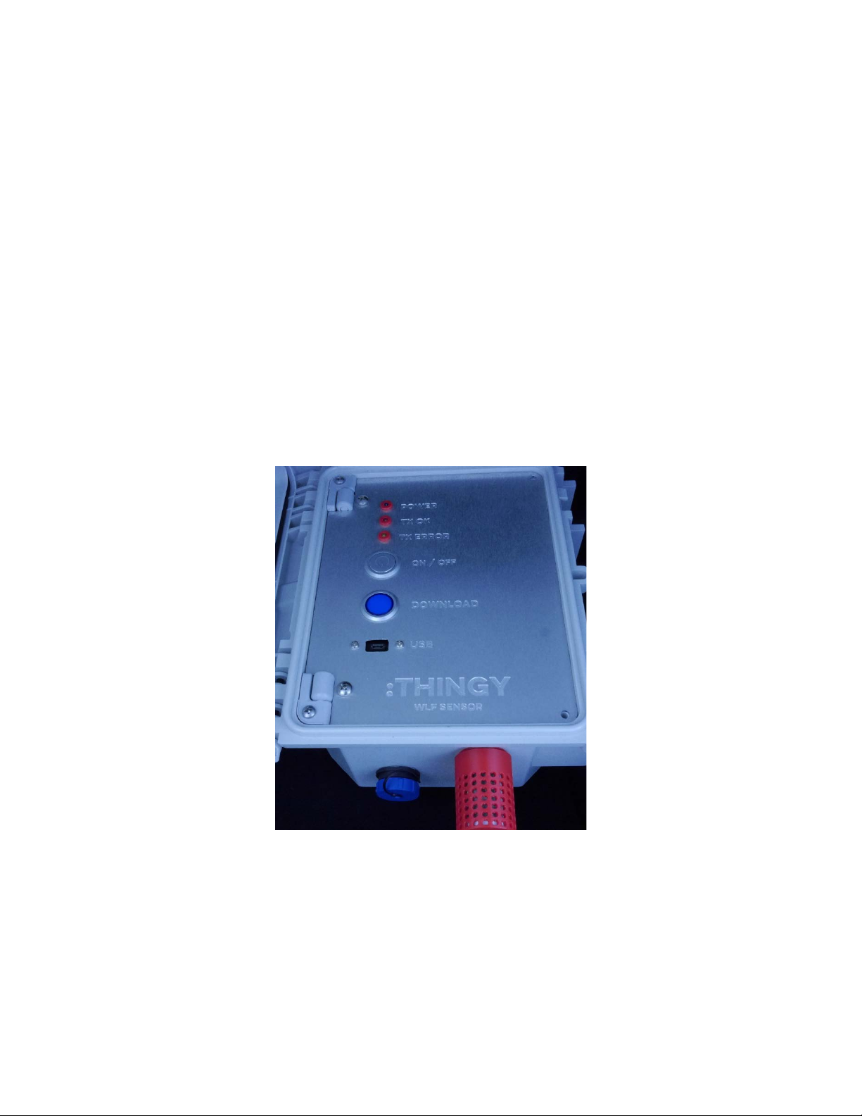
Sensor Node
Quick Start Guide
Thingy:AQ
Wildland Fire Real-Time Monitoring System
*PROTOTYPE DRAFT*
Version 1.0 ● January 9, 2018
Thingy, LLC – Bellevue, WA
Email – [email protected]
www.gothingy.com/WLF
Page 2

Thingy:AQ Sensor Node Quick Start Guide
Wildland Fire Real-Time Monitoring System – SENSOR NODE PROTOTYPE Version 1.0
© 2018 Thingy, LLC. All rights reserved.
Thingy, LLC
10641 SE 25
th
St
Bellevue, WA 98004
(425) 454-9933
www.gothingy.com
Trademarks
Thingy:AQ Sensor, Thingy:AQ Gateway, and T hingy Wildland Fire Real-Time Monitoring System are
registered trademarks of Thingy, LLC. All other trademarks or registered trademarks are the property
of their respective owners.
Disclaimer
The information provided in this document is provided "as is" without warranty of any kind. Thingy,
LLC disclaims all warranties, either express or implied, including the warranties of merchantability and
fitness for a particular purpose. In no event shall Thingy, LLC be liable for any damages whatsoever
including direct, indirect, incidental, consequential, loss of business profits or special damages, even if
Thingy, LLC or its suppliers have been advised of the possibility of such damages.
Document Lifetime
Thingy, LLC may occasionally update online documentation between releases of the related software
or hardware. Consequently, if this document was not downloaded recently, it may not contain the most
up-to-date information. Please refer to www.gothingy.com/support for the most current information.
From the Web site, you may also download and refresh this document if it has been updated, as
indicated by a change in this date: January 9, 2018.
Where to get help
Thingy, LLC support, product, and licensing information can be obtained as follows.
Product information — Documentation, release notes, software updates, and information about
Thingy, LLC products, licensing, and service, are at our T hingy, LLC website at:
http://www.gothingy.com/WLF
Technical support — Go to http://www.gothingy.com and select Support. On the Support page, you
will see several options, including one for making a service request. Note that to open a service
request, you must have a valid support agreement.
Your comments
Your suggestions will help us continue to improve the accuracy, organization, and overall quality of the
user publications. Please send your opinion of this document to:
[email protected]
If you have issues, comments, or questions about specific information or procedures, please include
the title and, if available, the part number, the revision, the page numbers, and any other details that
will help us locate the subject that you are addressing.
© Thingy, LLC 2018. All rights reserved. Page 2 of 15
Page 3

Thingy:AQ Sensor Node Quick Start Guide
Wildland Fire Real-Time Monitoring System –PROTOTYPE SENSOR NODE Version 1.0
1 Product Overview
Note: The Thingy:AQ real-time air quality monitoring and telemetry system described in this
guide was designed and built to meet the requirements of the InnoCentive Wildland Fire Sensor
Challenge - Challenge ID: 9933927
The system comprises of multiple Sensors Nodes and a Central Receiving Unit.
Communications between the Sensor Nodes and the Central Receiving Unit utilize LoRa (Long
Range Low Power) radio technology that offers a compelling mix of long range and low power
consumption. The system has been designed to be lightweight and easily deployable by a
single, non-specialist operator and to be suitable for harsh environments. The prototype
Thingy:AQ systems contains two main system components:
Thingy:AQ Sensor Nodes. These battery-powered Sensor Nodes (SN) measure air
pollutants including fine particulate matter PM
and ozone. The Sensor Nodes also measure air temperature, humidity and geo-location
data. A unique System ID identifying the Sensor Node, latitude, longitude and System
Error status are stored on the Sensor Node and are transmitted in real time over long
distance utilizing a LoRa encoded radio link.
, PM10, carbon monoxide, carbon dioxide
2.5
Thingy:AQ Central Receiving Unit. The central receiving unit (CRU), a physical
system, receives and centrally records data from multiple remote Sensor Nodes and
provides a USB port for interfacing into third party presentation platforms.
The Sensor Nodes include two 80um stainless steel particulate filters, one on the air inlet and
one on the exhaust from the Sensor Node. These filters limit both the ingress of larger pollutant
material and biological entities. To clean or replace the filters just turn the red filter housing
counter-clockwise to remove. Reverse this process to replace the filters.
1.1 Sensor Node
1.1.1 Sensor Node Overview
The Sensor Node housing incorporates the data logger electronics, a microSD card used for
logging the data, a GPS module for determining location information, a LoRa (Long Range)
radio module and the sensors embedded in a flow chamber. The GPS and LoRa antennas are
mounted directly to the top of the Sensor Node housing.
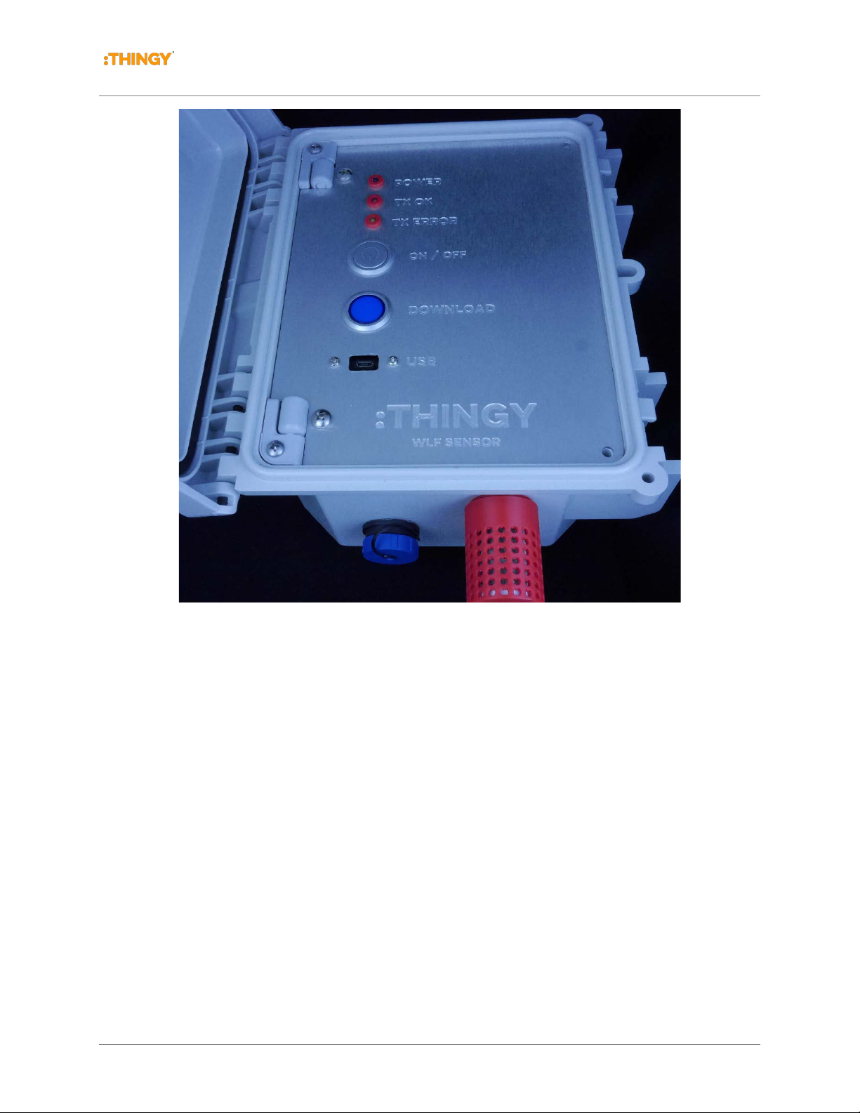
At the bottom of the Sensor Node housing (figure 1.1) are intake and exhaust filters for the
airflow. Air flow passes through a three-stage bio-mas filter assembly (3mm, 80um, 20um),
through the PM sensor into the sealed flow chamber where the airflow passes above the
remaining gas sensors through to the exhaust filter. The int ake is closest to the door and the
exhaust is behind the intake (toward the enclosure back).
The solar/battery/wall power connector is one with the blue cap to the left of the air filters.
© Thingy, LLC 2018. All rights reserved. Page 3 of 15
Page 4
Thingy:AQ Sensor Node Quick Start Guide
Wildland Fire Real-Time Monitoring System – SENSOR NODE PROTOTYPE Version 1.0
Figure 1.1 Thingy:AQ Sensor Node Housing with Inlet Air Filter
1.1.2 Sensor Nodes
The Sensor Nodes are designed to record and telemeter data with minimal or no operator
intervention. Once the system has been turned on, it will start measuring sensors, logging the
data and telemetering the data. The scan cycle time defines when the Sensor Node will start a
scan cycle, which involves powering up the particulate matter and CO2 sensors, waiting 15
seconds for the system to stabilize and then commencing a series of sensor measurements,
reading each sensor every 2 seconds multiple times before filtering, averaging, and storing the
data. At the end of the scan sequence, the Sensor Node powers down the sensors, powers up
the radio transmitter, telemeters the data and powers down the radio. The Sensor Node enters
a sleep state until the next scan cycle or input from the operator.
The only operator configurable variable is the Sensor Node Scan Interval (SI) cycle. The value
is stored in non-volatile memory and can be configured for a 1, 2, 5, 15, 20, 30 or 60 minute
scan interval. When the Sensor Node is powered on, it reads the scan interval configuration
from its non-volatile memory and automatically commences operation based on this parameter.
The operator can change this scan interval via the USB serial port on the Sensor Node. If the
© Thingy, LLC 2018. All rights reserved. Page 4 of 15
Page 5
Thingy:AQ Sensor Node Quick Start Guide
Wildland Fire Real-Time Monitoring System –PROTOTYPE SENSOR NODE Version 1.0
operator changes the scan interval, the new value is stored in non-volatile memory and
becomes the new power-on default value. The operator can interrogate system status, upload
system logs and upload recorded data via the Sensor Nodes USB interface. The data on the
Sensor Node is logged on the microSD card. The data can be read from this card without
removing the card. When the microSD card is swapped or replaced the system will
automatically commence logging to the media.
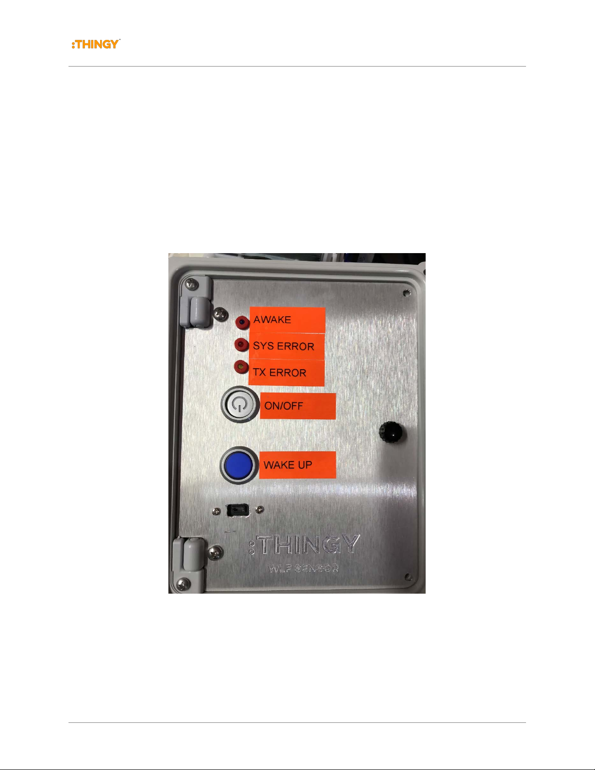
1.2 Sensor Node Front Panel
The front panel contains the logger’s ON/OFF switch, a WAKE UP switch, the micro USB sock et
and three indicator LEDs; AWAKE, SYS ERROR and TX ERROR.
Figure 1.2 Prototype Sensor Node Front Panel
1.2.1 POWER SWITCH
Turns the Sensor logger on or off.
© Thingy, LLC 2018. All rights reserved. Page 5 of 15
Page 6

Thingy:AQ Sensor Node Quick Start Guide
Wildland Fire Real-Time Monitoring System – SENSOR NODE PROTOTYPE Version 1.0
1.2.2 WAKE UP PUSH BUTTON
Wake the sensor up from deep sleep to enable configuration of the system, to upload data,
delete the data and log files etc, When the system is in deep sleep it can be woken up using this
push button by pushing the button for three seconds after which the AWAKE LED will flash
continuously while the logger is awake.
1.2.3 AWAKE LED
The WAKE LED is blue and it provides an indication of three separate states. When the logger
is turned on the blue LED will flash 6 times in rapid succession indication the processor is
operational, after a few seconds, the Power LED will flash approximately 10 times at a slower
rate indication the logger is initializing the hardware. When the initialization process is complete
the Power LED will remain illuminated for several minutes until the system go into deep sleep.
1.2.4 SYS ERROR LED
The SYS Error LED indicates a problem with the logger. This indicates either a problem with the
microSD card, a fault with one or more of the sensors or a low system voltage alarm.
1.2.5 TX ERROR LED
The TX ERROR LED will flash briefly in the event of an unsuccessful transmission of data via
the radio.
1.2.6 MICRO USB CONECTOR
The micro USB connector provides a USB serial interface to the logger. The logger will send
formatted data out of the serial interface at the end of the current scan interval. This interface
provides the user / operator interface to enable the configuration and interrogation of the logger
and to upload data and system log files from the logger to a terminal application.
© Thingy, LLC 2018. All rights reserved. Page 6 of 15
Page 7
Thingy:AQ Sensor Node Quick Start Guide
Wildland Fire Real-Time Monitoring System –PROTOTYPE SENSOR NODE Version 1.0
2 Installing, Starting and Stopping the
System
2.1 Powering up the system
2.1.1 External Battery Pack and Solar Charger
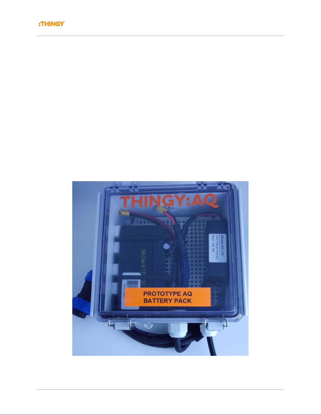
The Sensor Node Site Logger utilizes an external power supply enclosure (figure 2.1) which is
mounted on the mast (not shown in the picture). This enclosure contains a sealed lead acid
battery (SLA) and a solar charge controller. The battery is connected to the solar charger via a
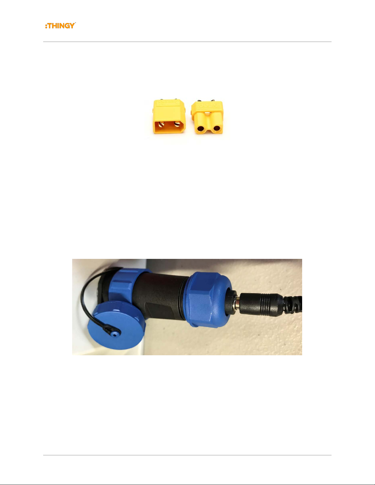
pair of in-line mating XT30 connectors. The system is shipped with the battery disconnected.
To connect the battery, open the enclosure door and connect the XT30 connectors (see figure
2.2a).
Figure 2.1 Thingy:AQ Sensor Node Battery Enclosure
© Thingy, LLC 2018. All rights reserved. Page 7 of 15
Page 8
Thingy:AQ Sensor Node Quick Start Guide
Wildland Fire Real-Time Monitoring System – SENSOR NODE PROTOTYPE Version 1.0
Figure 2.2a Thingy:AQ XC30 Connectors
2.1.2 Wall (AC) Power Option
The Sensor Node can also be powered with the supplied AC power supply and 2.1mm DC
power connector (see figure 2.2b). In this case you will not use the external battery pack.
Connect the supplied AC power supply (15VDC out to a 2.1mm barrel connector) to the power
adapter labeled WLF-Wall-Power. Then attach the adapter to the sensor housing connector.
The system is now ready to be powered on. Note in this configuration the sensor will not
operate without Wall power.
Figure 2.2a Thingy:AQ XC30 Connectors
2.2 Preparing the Sensor Nod e for Deployment
1. Mount the battery housing to the mast (if required)
2. Open the battery housing, connect the battery, close the battery housing
© Thingy, LLC 2018. All rights reserved. Page 8 of 15
Page 9

Thingy:AQ Sensor Node Quick Start Guide
Wildland Fire Real-Time Monitoring System –PROTOTYPE SENSOR NODE Version 1.0
3. Mount the Sensor Node enclosure with the provided mounting hardware on the
collapsible mast
4. Raise the mast to the required height
5. Open the Sensor Node logger enclosure
6. Open the front panel
7. Install a newly formatted microSD card into the microSD card socket
8. Close the front panel
9. Plug in either the battery housing, if fitted, or an external power supply
10. Turn on the logger via the ON/OFF push button switch.
11. If necessary, connect to via the USB port and configure the desired scan interval
12. Close the enclosure cover
2.3 Connecting to the Sensor Node Logger
When the operator connects to the USB interface it will be enumerated on the PC as a Silicon
Labs CP2102 USB-to-Serial port adapter. Modern operating systems, such as Windows 10,
include the required driver to recognize the USB interface as a serial device and to create a
logical serial port.
A quick way of determining the serial port in use on the PC is to inspect the PC’s serial port
table immediately before and immediately after plugging into the logger and noting the Comm
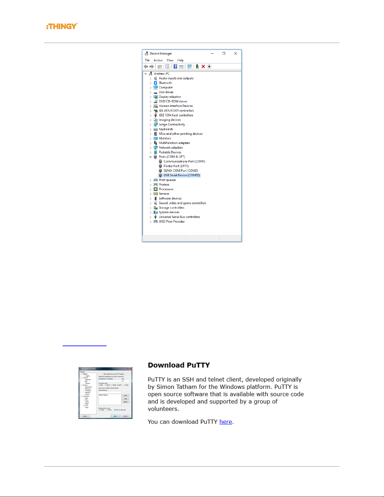
port number (Comm xx) of the newly creates device. Figures 2.3 is a screen capture of
Window’s Device Manager on Windows 10 showing a newly created Comm port (in this case
Comm20).
© Thingy, LLC 2018. All rights reserved. Page 9 of 15
Page 10
Thingy:AQ Sensor Node Quick Start Guide
Wildland Fire Real-Time Monitoring System – SENSOR NODE PROTOTYPE Version 1.0
Figure 2.3 Windows Device Manager after plugging in the Sensor Node
2.3.1 Configuring the T erminal application
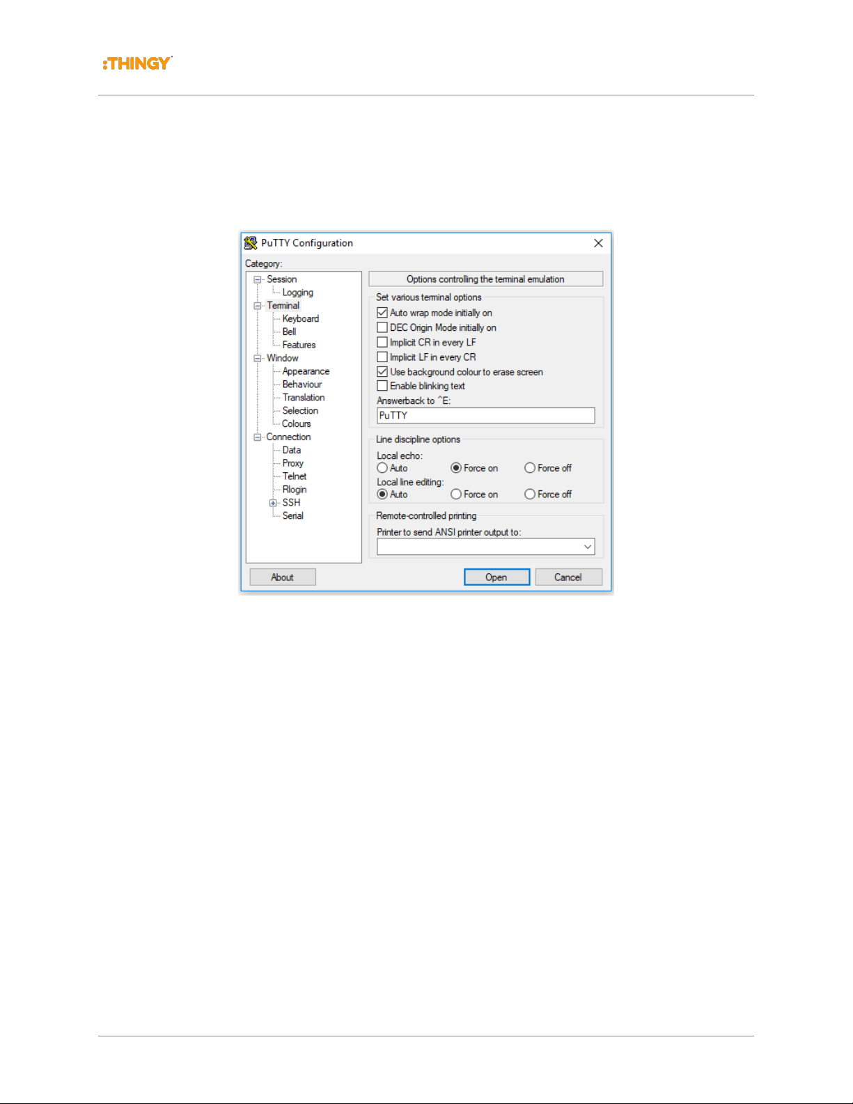
When using a PC, open your preferred terminal application and configure the terminal
application to use the newly created serial port and to select local echo mode.
If you do not have a suitable terminal application these are several freeware terminal
applications available. One example for Windows is Putty (figure 2.4) which can be downloaded
here: www.putty.org
Figure 2.4 Putty Terminal Program for Windows
© Thingy, LLC 2018. All rights reserved. Page 10 of 15
Page 11
Thingy:AQ Sensor Node Quick Start Guide
Wildland Fire Real-Time Monitoring System –PROTOTYPE SENSOR NODE Version 1.0
When the terminal application on the PC is started, configure the serial interface attributes.
Set the Terminal to 57600 baud, 8 bit data, 1 stop, no parity, no flow control, local echo.
Figure 2.5 Putty Configuration Screen for Local Echo
2.4 User Interface
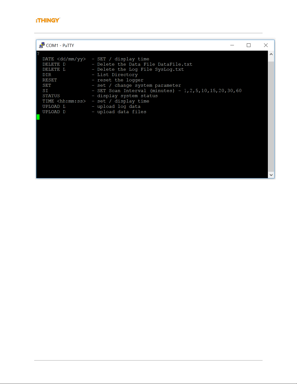
The logger provides a help screen. Help can be access using the short cut ? cha racter followed
by ENTER (carriage return / line feed).
© Thingy, LLC 2018. All rights reserved. Page 11 of 15
Page 12
Thingy:AQ Sensor Node Quick Start Guide
Wildland Fire Real-Time Monitoring System – SENSOR NODE PROTOTYPE Version 1.0
Figure 2.6 User Interface Help Output
2.4.1 Scan Interval
The scan interval determines the time interval between the logger sensor scan sequences and
is configured using the SET SI command. Example:
minutes. The scan interval is stored in nonvolatile memory and becomes the power-on default
value until changed again by the next SET SI command.
SET SI 5 will set the scan interval to 5
2.4.2 Status Command
The status command will display the logger’s health status
2.4.3 Directory Listing
The directory contents of the logger’s microSD card can be viewed using the DIR command.
2.4.4 Upload Commands and Delete
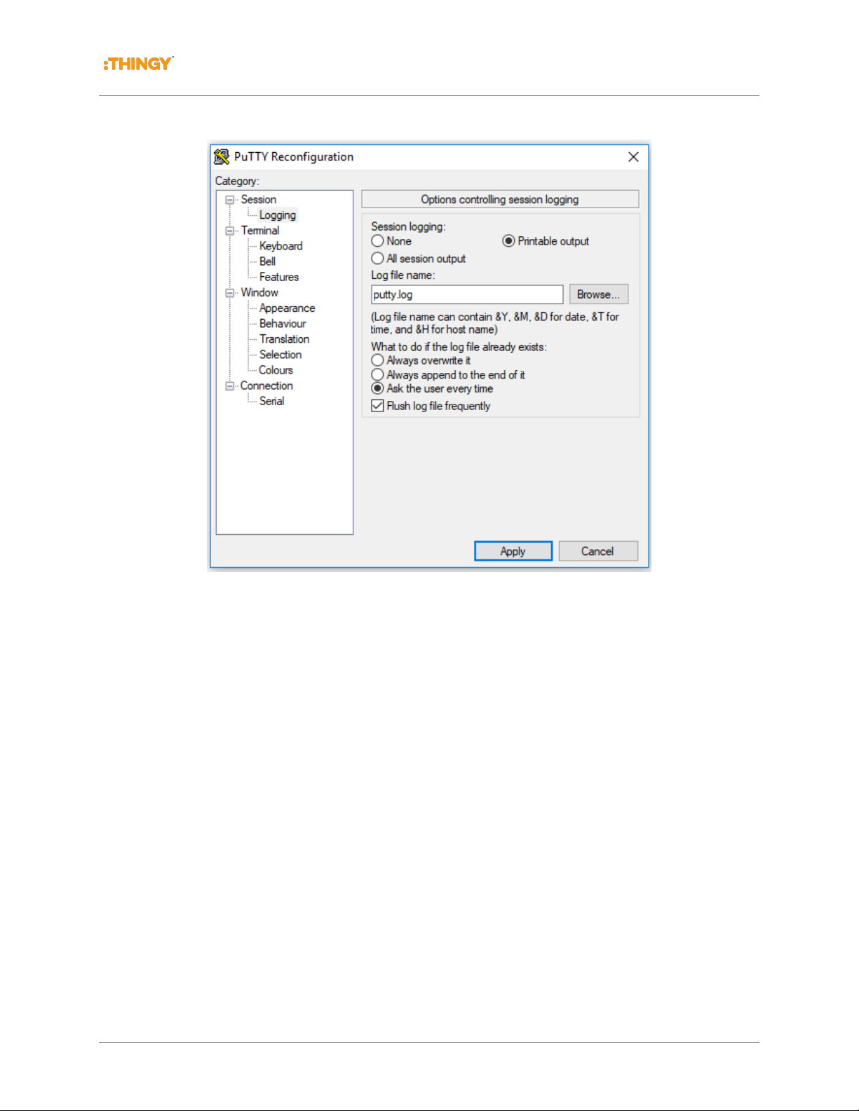
The upload commands are used to upload the status log file and the data file from the logger’s
microSD card to the terminal application. This data can then be logged to the PC via the
terminal application’s capture capability. The following screen capture shows the configuration
of the Putty application to capture the console output.
© Thingy, LLC 2018. All rights reserved. Page 12 of 15
Page 13
Thingy:AQ Sensor Node Quick Start Guide
Wildland Fire Real-Time Monitoring System –PROTOTYPE SENSOR NODE Version 1.0
Figure 2.7 Configuring Logging (capture) with Putty Terminal Application
2.4.4.1 UPLOAD D
The data file can be uploaded using the UPLOAD D command.
2.4.4.2 DELETE D
Once the data has been uploaded via the terminal application and the user has confirmed the
successful upload by viewing the contents of the uploaded file, the data file can be deleted from
the logger via the
DELETE D command.
2.4.4.3 UPLOAD L
The Sensor Node also produces status log records for the power on reset initialization of the
logger. This file contains sensor configuration data extracted from the sensors. This file can be
uploaded using the
UPLOAD L command.
© Thingy, LLC 2018. All rights reserved. Page 13 of 15
Page 14

Thingy:AQ Sensor Node Quick Start Guide
Wildland Fire Real-Time Monitoring System – SENSOR NODE PROTOTYPE Version 1.0
2.4.4.4 DELETE L
The log file can be deleted with the DELETE L command.
2.4.5 Reading the microSD card
Instead of uploading the data file via the terminal application, the user can instead to remove the
microSD card from the logger and inserting it into the PC to read the file directly from the
MicroSD card. The logger accepts MicroSD cards formatted as either FAT16 or FAT32.
© Thingy, LLC 2018. All rights reserved. Page 14 of 15
Page 15
Thingy:AQ Sensor Node Quick Start Guide
Wildland Fire Real-Time Monitoring System –PROTOTYPE SENSOR NODE Version 1.0
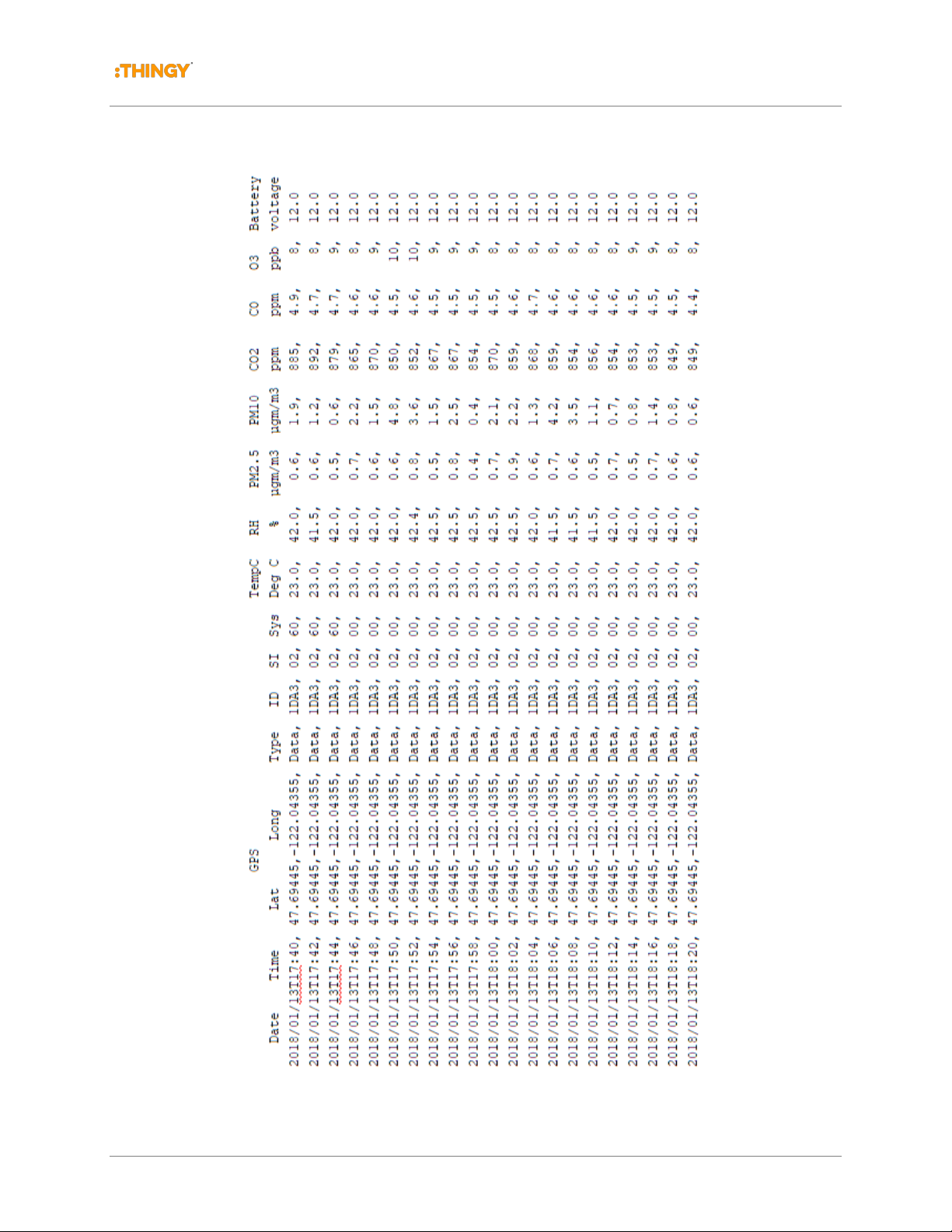
2.5 Sample Data Format
Figure 2.8 Sample Data Upload
© Thingy, LLC 2018. All rights reserved. Page 15 of 15
 Loading...