

Page 1
Vega Reader Setup Guide
875-0030-03 RevA
Page 2

Government Limited Rights Notice: All documentation and manuals
were developed at private expense and no part of it was developed using
Government funds.
The U.S. Government’s rights to use, modify, reproduce, release, perform,
display, or disclose the technical data contained herein are restricted by
paragraph (b)(3) of the Rights in Technical Data — Noncommercial Items
clause (DFARS 252.227-7013(b)(3)), as amended from time-to-time. Any
reproduction of technical data or portions thereof marked with this legend
must also reproduce the markings. Any person, other than the U.S.
Government, who has been provided access to such data must promptly
notify Trimble.
ThingMagic, Mercury, Reads Any Tag, and the ThingMagic logo are
trademarks or registered trademarks of Trimble.
Other product names mentioned herein may be trademarks or registered
trademarks of Trimble or other companies.
©2011 ThingMagic – a division of Trimble Navigation Limited. ThingMagic
and The Engine in RFID are registered trademarks of Trimble Navigation
Limited. Other marks may be protected by their respective owners. All
Rights Reserved.
ThingMagic, A Division of Trimble
One Cambridge Center, 11th floor
Cambridge, MA 02142
866-833-4069
03 Revision A
August, 2011
Page 3

Contents
ThingMagic Vega
Set Up Guide . . . . . . . . . . . . . . . . . . . . . . . . . . . . . . . . . . . . . . . . . . . . . . . . . . . . . . . . . . . . . . . .5
Introduction . . . . . . . . . . . . . . . . . . . . . . . . . . . . . . . . . . . . . . . . . . . . . . . . . . . . . . . . . . . . . . . . . . . . . . . . . . . . . . . . . 6
In-vehicle Reader Notes . . . . . . . . . . . . . . . . . . . . . . . . . . . . . . . . . . . . . . . . . . . . . . . . . . . . . . . . . . . . . . . . . 6
Included Components. . . . . . . . . . . . . . . . . . . . . . . . . . . . . . . . . . . . . . . . . . . . . . . . . . . . . . . . . . . . . . . . . . . . . . . . 7
Additional required equipment: . . . . . . . . . . . . . . . . . . . . . . . . . . . . . . . . . . . . . . . . . . . . . . . . . . . . . . . . . . . 7
Setting up Vega . . . . . . . . . . . . . . . . . . . . . . . . . . . . . . . . . . . . . . . . . . . . . . . . . . . . . . . . . . . . . . . . . . . . . . . . . . . . . 8
Connecting the Antenna(s) . . . . . . . . . . . . . . . . . . . . . . . . . . . . . . . . . . . . . . . . . . . . . . . . . . . . . . . . . . . . . . 8
Using Three Antennas. . . . . . . . . . . . . . . . . . . . . . . . . . . . . . . . . . . . . . . . . . . . . . . . . . . . . . . . . . . . . . . . 8
Powering up Vega. . . . . . . . . . . . . . . . . . . . . . . . . . . . . . . . . . . . . . . . . . . . . . . . . . . . . . . . . . . . . . . . . . . . . . 9
Reading Tags. . . . . . . . . . . . . . . . . . . . . . . . . . . . . . . . . . . . . . . . . . . . . . . . . . . . . . . . . . . . . . . . . . . . . . . . . . . . . . .10
Start the Universal Reader Assistant. . . . . . . . . . . . . . . . . . . . . . . . . . . . . . . . . . . . . . . . . . . . . . . . . . . . . . 10
Using GPIO and ReaderEnable . . . . . . . . . . . . . . . . . . . . . . . . . . . . . . . . . . . . . . . . . . . . . . . . . . . . . . . . . . . . . .11
GPIO . . . . . . . . . . . . . . . . . . . . . . . . . . . . . . . . . . . . . . . . . . . . . . . . . . . . . . . . . . . . . . . . . . . . . . . . . . . . . . . 11
GPIO Logic Voltage Levels . . . . . . . . . . . . . . . . . . . . . . . . . . . . . . . . . . . . . . . . . . . . . . . . . . . . . . . . . . 11
ReaderEnable . . . . . . . . . . . . . . . . . . . . . . . . . . . . . . . . . . . . . . . . . . . . . . . . . . . . . . . . . . . . . . . . . . . . . . . . 12
Mechanical . . . . . . . . . . . . . . . . . . . . . . . . . . . . . . . . . . . . . . . . . . . . . . . . . . . . . . . . . . . . . . . . . . . . . . . . . . . . . . . . .13
Mounting the Reader . . . . . . . . . . . . . . . . . . . . . . . . . . . . . . . . . . . . . . . . . . . . . . . . . . . . . . . . . . . . . . . . . . 13
Rack Mount Considerations. . . . . . . . . . . . . . . . . . . . . . . . . . . . . . . . . . . . . . . . . . . . . . . . . . . . . . . . . . . . . 14
Elevated Operating Ambient . . . . . . . . . . . . . . . . . . . . . . . . . . . . . . . . . . . . . . . . . . . . . . . . . . . . . . . . . 14
Reduced Air Flow . . . . . . . . . . . . . . . . . . . . . . . . . . . . . . . . . . . . . . . . . . . . . . . . . . . . . . . . . . . . . . . . . . 14
Mechanical Loading . . . . . . . . . . . . . . . . . . . . . . . . . . . . . . . . . . . . . . . . . . . . . . . . . . . . . . . . . . . . . . . . 14
Circuit Overloading . . . . . . . . . . . . . . . . . . . . . . . . . . . . . . . . . . . . . . . . . . . . . . . . . . . . . . . . . . . . . . . . . 14
Reliable Earthing . . . . . . . . . . . . . . . . . . . . . . . . . . . . . . . . . . . . . . . . . . . . . . . . . . . . . . . . . . . . . . . . . . . 14
Vega Specifications . . . . . . . . . . . . . . . . . . . . . . . . . . . . . . . . . . . . . . . . . . . . . . . . . . . . . . . . .15
Power . . . . . . . . . . . . . . . . . . . . . . . . . . . . . . . . . . . . . . . . . . . . . . . . . . . . . . . . . . . . . . . . . . . . . . . . . . . . . . . 15
AC/DC Power Required . . . . . . . . . . . . . . . . . . . . . . . . . . . . . . . . . . . . . . . . . . . . . . . . . . . . . . . . . . . . . 15
Environment . . . . . . . . . . . . . . . . . . . . . . . . . . . . . . . . . . . . . . . . . . . . . . . . . . . . . . . . . . . . . . . . . . . . . . . . . . 15
Operating Temp . . . . . . . . . . . . . . . . . . . . . . . . . . . . . . . . . . . . . . . . . . . . . . . . . . . . . . . . . . . . . . . . . . . 15
Storage Temp . . . . . . . . . . . . . . . . . . . . . . . . . . . . . . . . . . . . . . . . . . . . . . . . . . . . . . . . . . . . . . . . . . . . . 15
3
Page 4

Automotive Environmental Standards . . . . . . . . . . . . . . . . . . . . . . . . . . . . . . . . . . . . . . . . . . . . . . . . . . 16
Electrostatic Discharge. . . . . . . . . . . . . . . . . . . . . . . . . . . . . . . . . . . . . . . . . . . . . . . . . . . . . . . . . . . . . . 16
Architecture . . . . . . . . . . . . . . . . . . . . . . . . . . . . . . . . . . . . . . . . . . . . . . . . . . . . . . . . . . . . . . . . . . . . . . . . . . 16
RFID ASIC . . . . . . . . . . . . . . . . . . . . . . . . . . . . . . . . . . . . . . . . . . . . . . . . . . . . . . . . . . . . . . . . . . . . . . . . 16
User-accessible Flash Memory . . . . . . . . . . . . . . . . . . . . . . . . . . . . . . . . . . . . . . . . . . . . . . . . . . . . . . . 16
Tag Buffer . . . . . . . . . . . . . . . . . . . . . . . . . . . . . . . . . . . . . . . . . . . . . . . . . . . . . . . . . . . . . . . . . . . . . . . . 16
Performance . . . . . . . . . . . . . . . . . . . . . . . . . . . . . . . . . . . . . . . . . . . . . . . . . . . . . . . . . . . . . . . . . . . . . . . . . 17
Tag Read Rate. . . . . . . . . . . . . . . . . . . . . . . . . . . . . . . . . . . . . . . . . . . . . . . . . . . . . . . . . . . . . . . . . . . . . 17
Tag Read Distance . . . . . . . . . . . . . . . . . . . . . . . . . . . . . . . . . . . . . . . . . . . . . . . . . . . . . . . . . . . . . . . . . 17
Tag / Transponder Protocols . . . . . . . . . . . . . . . . . . . . . . . . . . . . . . . . . . . . . . . . . . . . . . . . . . . . . . . . . . . . 17
RFID Protocol Support . . . . . . . . . . . . . . . . . . . . . . . . . . . . . . . . . . . . . . . . . . . . . . . . . . . . . . . . . . . . . . 17
Regional Support . . . . . . . . . . . . . . . . . . . . . . . . . . . . . . . . . . . . . . . . . . . . . . . . . . . . . . . . . . . . . . . . . . 17
RF Interface . . . . . . . . . . . . . . . . . . . . . . . . . . . . . . . . . . . . . . . . . . . . . . . . . . . . . . . . . . . . . . . . . . . . . . . . . . 17
Antenna Connector . . . . . . . . . . . . . . . . . . . . . . . . . . . . . . . . . . . . . . . . . . . . . . . . . . . . . . . . . . . . . . . . . 17
RF Power Output . . . . . . . . . . . . . . . . . . . . . . . . . . . . . . . . . . . . . . . . . . . . . . . . . . . . . . . . . . . . . . . . . . 17
Data/Control Interface . . . . . . . . . . . . . . . . . . . . . . . . . . . . . . . . . . . . . . . . . . . . . . . . . . . . . . . . . . . . . . . . . 18
Data/Control . . . . . . . . . . . . . . . . . . . . . . . . . . . . . . . . . . . . . . . . . . . . . . . . . . . . . . . . . . . . . . . . . . . . . . 18
GPIO Sensors and Controls . . . . . . . . . . . . . . . . . . . . . . . . . . . . . . . . . . . . . . . . . . . . . . . . . . . . . . . . . 18
Protocol . . . . . . . . . . . . . . . . . . . . . . . . . . . . . . . . . . . . . . . . . . . . . . . . . . . . . . . . . . . . . . . . . . . . . . . . . . 18
Physical . . . . . . . . . . . . . . . . . . . . . . . . . . . . . . . . . . . . . . . . . . . . . . . . . . . . . . . . . . . . . . . . . . . . . . . . . . . . . 18
Dimensions . . . . . . . . . . . . . . . . . . . . . . . . . . . . . . . . . . . . . . . . . . . . . . . . . . . . . . . . . . . . . . . . . . . . . . . 18
Compliance Information . . . . . . . . . . . . . . . . . . . . . . . . . . . . . . . . . . . . . . . . . . . . . . . . . . . . .19
FCC COMPLIANCE. . . . . . . . . . . . . . . . . . . . . . . . . . . . . . . . . . . . . . . . . . . . . . . . . . . . . . . . . . . . . . . . . . . 19
4
Page 5

ThingMagic Vega
Set Up Guide
ThingMagic Vega Set Up Guide 5
Page 6

Introduction
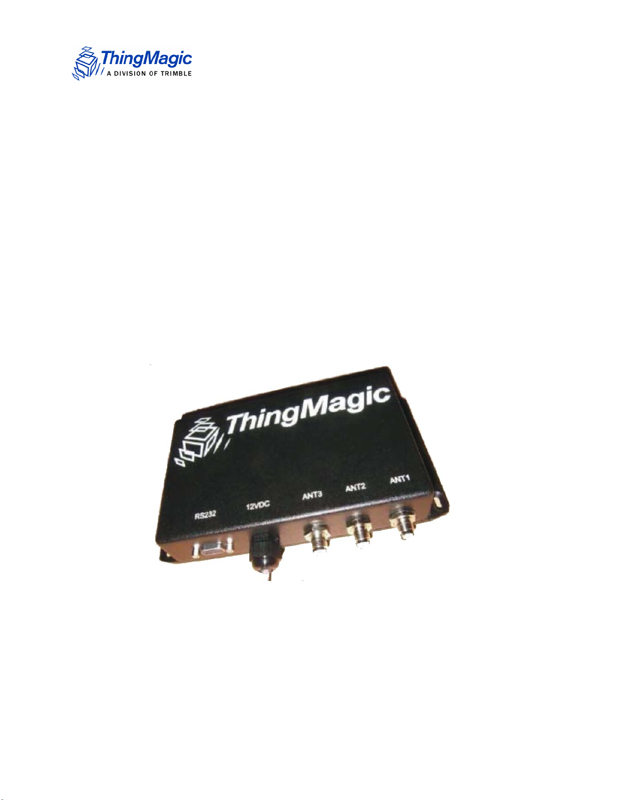
The Vega Reader kit is a self-contained reader that can be deployed as a UHF RFID reader
with a standard serial interface. The Vega is built on the ThingMagic M5e module. For
more information on the M5e please see the M5e-Family Developer’s Guide.
This document provides an overview of the hardware and basic command and control of
the Vega. The ThingMagic Vega RFID Reader is compatible with ThingMagic’s
application development tools, including the cross-product MercuryAPI, permitting rapid
creation of solutions to support a wide range of applications.
The MercuryAPI supports Java, .NET and C programming environments. The
MercuryAPI Software Development Kit (SDK) contains sample applications and source
code to help developers get started demoing and developing functionality. For more
information on the MercuryAPI see the MercuryAPI Programmers Guide and the
MercuryAPI SDK, available on the ThingMagic website.
A demo application which supports reading and writing is provided in the MercuryAPI
SDK package. The source code for this example is included in the MercuryAPI SDK
package under /cs/samples/exe/Universal-Reader-Assistant.exe.
Introduction
See the Readme.txt in /cs/samples/Universal-Reader-Assistant/Universal-ReaderAssistant for usage details.
See the MercuryAPI Programming Guide for details on using the MercuryAPI.
Note
In some cases the configuration of the Vega differs from that specified for
the standalone Mercury5e module. These cases are noted in this document.
In-vehicle Reader Notes
The contents of the Vega Setup Guide apply to both the Vega RS (Ruggedized System)
and the Vega IVR (In-Vehicle Reader). The IVR variant has the following exceptions:
The components included with the product are different, see Included Components.
The ReaderEnable jumper terminator is not included so the ReaderEnable/DTR signal
(see Serial Connector Pin Out
no power.
) must be managed or the reader will stay off and draw
6 ThingMagic Vega Set Up Guide
Page 7

Included Components
Included Components
With the Vega RS, you will receive the following components:
The ThingMagic Vega reader
One, Two or Three antennas and Cables, depending on your configuration
Documentation and software development kit packages can be found at
http://rfid.thingmagic.com/devkit
One Jumper Terminator for the ReaderEnable on the GPIO Connector. (Not included
with the IVR)
Note: If the ReaderEnable jumper is not connected another method must be used to “turn on”
the reader as described in ReaderEnable
Additional required equipment:
.
Straight-thru DB9 serial cable.
USB to Serial adapter (if the connected PC doesn’t have an RS232 COM port)
One DC power supply with power cord (Optional)
Note: This product is intended to be supplied by a Listed power supply marked ‘LPS’ or ‘NEC
Class 2’ and rated 8-16V, minimum 1A.
WARNING!
The Vega antenna ports may be susceptible to damage from Electrostatic
Discharge (ESD). Equipment failure can result if the antenna or communication
ports are subjected to ESD. Standard ESD precautions should be taken during
installation and operation to avoid static discharge when handling or making
connections to the Vega reader antenna or communication ports. Environmental
analysis should also be performed to ensure static is not building up on and
around the antennas, possibly causing discharges during oper ation. See the
M5e-Family Developer’s Guide | Appendix E or contact
support@thingmagic.com for more details on ESD.
ThingMagic Vega Set Up Guide 7
Page 8

Setting up Vega
When setting up Vega, use the following procedures:
1. Connecting the Antenna(s)
2. Powering up the Vega
3. Connecting the Serial Cable
Connecting the Antenna(s)
ThingMagic supplies a variety of monostatic antenna types for use with Vega. Vega supports up
to three antennas. Use the following procedure to connect the antenna to the Vega.
WARNING!
Setting up Vega
To prevent damage to Vega, never apply RF power to an antenna port that
does not have an antenna or terminator connected to it.
1. If the antenna does not have an integrated cable, connect one end of the coax cable
to the antenna.
2. Connect the other end of the coax cable to Ant 1, Ant 2 or Ant 3 antenna port on the front of
the module.
Using Three Antennas
The antenna port configuration uses a combination of two configuration settings (antenna
port and GPO #1) for the three antennas:
Table 1: Antenna Configuration Settings
Antenna Port Setting GPO #1 Setting
Antenna 1 TX=2, RX=2 n/a
Antenna 2 TX=1, RX=1 High
Antenna 3 TX=1, RX=1 Low (default)
8 ThingMagic Vega Set Up Guide
Page 9

Setting up Vega
Note
In order to use the Antenna 2 port it is necessary to set the antenna
configuration and toggle the GPIO Output #1 to High.
When using the MercuryAPI (v1.9 and later) to develop Vega applications the GPIO
mapping for antenna configuration is handled for you. You can simply specify antennas
as 1, 2 and 3 and they will map to the labels on the Vega. If using low level serial
commands the GPO configuration needs to be handled “manually” using the settings
described in the Using a Multiplexer section of the M5e-Family Developer’s Guide to
create the mappings in Antenna Configuration Settings
Powering up Vega
After connecting the antenna (s) and terminating any unused ports, you can power up Vega.
1. Connect the serial cable from a PC to Vega
Table 2: Serial Connector Pin Out
Pin Number Description
2 RXD – to host
3 TXD – from host
4 DTR – ReaderEnable1 Input
5 Ground
9+5V
2. Apply 12VDC power to the power input connector, J1.
3. Insure that the ReaderEnable Jumper Terminator is connected to the GPIO
connector
For more on the ReaderEnable signal see Using GPIO and ReaderEnable
The reader is now powered up and ready to begin reading tags.
below
ThingMagic Vega Set Up Guide 9
Page 10

Reading Tags
The following procedure explains how to install and activate the Reader Assistant on your PC.
Start the Universal Reader Assistant
1. Get Univ ers al- Reader -Assist ant fr om the ThingM agic website, it s part of the
MercuryAPI SDK package under /cs/samples/exe/Universal-Reader-Assistant.exe,
and insall it on the compute r that is c onnected to the USB Reader
( http://rfid.thingmagic.com/devkit).
2. Set up the computer to Vega as described in Setting up Vega
3. Start the Universal Reader Assistant by double-clicking the executable file Universal-
Reader-Assistant.exe.
4. Select the appropriate COM port for Reader URI.
Reading Tags
The Universal Reader Assistant senses the COM ports that are located on your
system.
When using an RS232 COM port it is typically statically assigned COM1.
If using a USB to Serial adapter, USB devices are typically assigned higer value COM
ports. If many COM ports are listed in the menu and you aren’t sure which is for the USB
Adapter you can find the assigned value using the Windows Device Manager:
a. Open the Device Manager (located in Control Pa nel | System)
b. Select the Hardware tab and click Device Manger"
c. Select View | Devices by Type | Port s (COM & LPT)
The device appears as USB Serial Port (COM#). The USB adapter COM port value
is in parentheses.
5. Follow the Readme.txt in /cs/samples/Universal-Reader-Assistant for steps to read
and write tags.
10 ThingMagic Vega Set Up Guide
Page 11

Using GPIO and ReaderEnable
Two general purpose inputs, one general purpose output and the ReaderEnable input are
provided through a 6 position Tyco Amp 1445049-6 Connector (Mating Shell: 1445022-6,
Mating Contact: 794610-3). GPIO describes the pin out for this connector.
GPIO
The GPIO signals can be accessed using the Config tab on Reader Assistant as
described in the previous section.
Table 3: GPIO connector pin out
Pin Number/
Wire Color
1 - J2 White Input -0.5 5.5 GPI 1
2 - J2 Brown Input -0.5 5.5 GPI 2
Direction Vmin Vmax Description
Using GPIO and ReaderEnable
3 - J2 Yellow Output 0 3.6 GPO 2
Note: This is not an open collector
output. It is a 74LVC244A output.
4 - J2 Blue Input -0.5 Vin + 0.5 ReaderEnable2
5 - J2 Purple In/Out 8 16 +12V (same as Vin)
6 - J2 Green In/Out 0 0 Ground
GPIO Logic Voltage Levels
The following are the voltage levels between Ground (Green) and the input or output pin
for logic high and low:
Inputs
Low - apply a signal between 0 and 0.8 V
High - apply a signal between 2 and 5 V
Outputs
Low - outputs a maximum 0.4 V and will sink 12mA
High - outputs a minimum of 2.4 V and will source 12mA.
ThingMagic Vega Set Up Guide 11
Page 12

Using GPIO and ReaderEnable
Note: Note that there is no GPO-1 connection. This signal is used for switching between
antennas 2 and 3.
Figure 1: Connector Cable
ReaderEnable
There are two connections that can be used to enable the reader. The Serial connector
provides access to the ReaderEnable1 signal. The GPIO connector provides access to
the ReaderEnable2 signal. At least one of these signals must be pulled to greater than
+2V for the reader to be active. These signals can be used to remotely turn the power off
for power savings. The ReaderEnable Jumper Terminator provided with your reader will
connect pins 4 and 5 of the GPIO connector providing +12VDC to the ReaderEnable2
input.
12 ThingMagic Vega Set Up Guide
Page 13
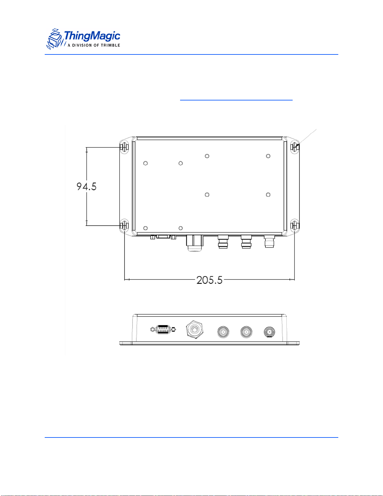
Mechanical
The reader mounting is as shown in Vega Mechanical (all dimensions in cm). The four
mounting holes are designed for M4 screws with lock washers and 15mm x 1.5mm flat
washers.
Mechanical
Figure 2: Vega Mechanical (all dimensions in cm)
Mounting the Reader
To mount the reader on a ceiling or wall, follow these steps:
1. Hold the reader in its mounting location and mark the position of the four mounting
screws.
ThingMagic Vega Set Up Guide 13
Page 14

Mechanical
2. Drill holes for the screws and install wall or ceiling anchors if required. For ceiling
mount, use only anchors specifically designed for ceilings.
3. Hold reader over holes and insert the screws and tighten until almost flush with the
wall.
4. Tighten the screws.
Rack Mount Considerations
Elevated Operating Ambient
If installed in a closed or multi-unit rack assembly, the operating ambient temperature of
the rack environment may be greater than room ambient. Therefore, consideration should
be given to installing the equipment in an environment compatible with the maximum
Operating Temp
.
Reduced Air Flow
Installation of the equipment in a rack should be such that the amount of air flow required
for safe operation of the equipment is not compromised.
Mechanical Loading
Mounting of the equipment in the rack should be such that a hazardous condition is not
achieved due to uneven mechanical loading.
Circuit Overloading
Consideration should be given to the connection of the equipment to the supply circuit
and the effect that overloading of the circuits might have on overcurrent protection and
supply wiring. Appropriate consideration of equipment nameplate ratings should be used
when addressing this concern.
Reliable Earthing
Reliable earthing of rack-mounted equipment should be maintained. Particular attention
should be given to supply connections other than direct connections to the branch circuit
(e.g. use of power strips).
14 ThingMagic Vega Set Up Guide
Page 15

Vega Specifications
Power
AC/DC Power Required
Reader : 10-16 VDC, 8 W maximum at 12 V when transmitting
Optional AC Power Adapter: 100-240 VDC, 50-60 Hz, 10 W maximum when
transmitting
Note
If an AC Power Adapter supply is used it must meet the following criteria:
- Be UL Listed
- Meet the above operating specs
- The output must comply with SELV and LPS characteristics
- Have a maximum operating ambient temperature that meets or exceeds the intended
Vega operating temperatures as covered under the UL Listing of the power supply.
Environment
Operating Temp
Reader: -40 C to +75 C
Note
If an external DC power supply with a lower operating ambient temperature, as covered
under the UL Listing of the power supply, is used then the operating ambient temperature of
the Vega would be reduced accordingly.
Storage Temp
Reader: –40C to +85C
Vega Specifications 15
Page 16

Automotive Environmental Standards
Confirmed to meet in-vehicle standards for:
Powered Thermal Cycle (IEC 68-2-14wNb)
Thermal Shock Resistance A & B (IEC 68-2-14Na)
Powered Vibration Endurance (IEC 68-2-6)
Mechanical Shock (IEC 68-2-32, 68-2-27)
Humidity-Temperature Cycle (
Water/Fluids Ingress (IEC Pub. 529 Sec. 14.2)
Connector/Harness Pull-Push (
Voltage Overstress
Electrostatic Discharge
Electrostatic Discharge
– IEC-61000-4-2 discharge direct to operational antenna port tolerates max 300 Volt
Pulse
– MIL-883 3015.7 discharge direct to operational antenna port tolerates max 1200
Volt Pulse
Survival level varies with antenna return loss and antenna characteristics. See the
M5e-Family Developers Guide for methods to increase ESD tolerances.
Architecture
RFID ASIC
Intel R1000
User-accessible Flash Memory
16 kB
Tag B u f f e r
200 tags
16 Vega Specifications
Page 17

Performance
Tag Read Rate
Up to 190 tags/second
Tag Read Distance
Over 30 feet (9 m) with 6 dBi antenna (36 dBm EIRP)
Tag / Transponder Protocols
RFID Protocol Support
EPCglobal Gen 2 (ISO 18000-6C) with Anti-Collision, DRM, and advanced antijamming
Regional Support
Certification obtained or in progress for the following regions: North and South
America, EU, Korea and other Asia-PAC countries.
RF Interface
Antenna Connector
Three reverse-TNC antenna ports supporting monostatic 50 Ohm antennas (for best
performance VSWR should be less than 1.5:1 in operating frequency range).
RF Power Output
Separate read and write levels, command-adjustable from 5 dBm to 30 dBm (1 W),
+/-1.0 dBm accuracy.
Vega Specifications 17
Page 18

Data/Control Interface
Data/Control
9-pin serial connector, supporting RS232 with asynchronous data rates up to 921.6
kbps. DTR signal turns off reader completely to conserve power.
GPIO Sensors and Controls
2 General Purpose inputs and one output, accessible via Molex Connector
Protocol
Command-response protocol protected by length field and 16-bit CRC.
Physical
Dimensions
8.5 in L x 5.25 in W x 1.5 in H
(21.6 cm x 13.3 cm x 3.8 cm)
18 Vega Specifications
Page 19

Compliance Information
FCC COMPLIANCE
FCC ID: QV5SR5E
This equipment complies with Part 15 of the FCC rules for intentional radiators and Class
A digital devices when installed and used in accordance with the instruction manual.
Following these rules provides reasonable protection against harmful interference from
equipment operated in a commercial area.
This equipment should not be installed in a residential area as it can radiate radio
frequency energy that could interfere with radio communications, a situation the user
would have to fix at their own expense.
This device has been designed to operate with the antennas provided with it (MTI MT-
262024) and having a maximum gain of 7dBic. Antennas not listed here or having a gain
greater than 7dBic are strictly prohibited for use with this device. The required antenna
impedance is 50 ohms.
To reduce radio interference to other users, the antenna type and its gain is chosen such
that the equivalent isotropically radiated power (EIRP) is not more than permitted for
successful communication.
EQUIPMENT MODIFICATION CAUTION
Equipment changes or modifications not expressly approved by ThingMagic, Inc., the
party responsible for FCC compliance, could void the user's authority to operate the
equipment and could create a hazardous condition.
IMPORTANT USER INFORMATION
In order to comply with FCC and IC requirements for RF exposure safety, a separation
distance of at least 20 cm (7.9 in) needs to be maintained between the radiating elements of
the antenna and the bodies of nearby persons.
Compliance Information 19
Page 20

20 Compliance Information
 Loading...