

Page 1
A DIVISION OF TRIMBLE
875-0072-02 Rev A
Mer cury®xPRESS Platf orm Guide
SDK Version 1.7.1
1
Page 2

A DIVISION OF TRIMBLE
Government Limited Rights Notice: All documentation and manuals were developed at
private expense and no part of it was developed using Government funds.
The U.S. Government’s rights to use, modify, reproduce, release, perform, display, or
disclose the technical data contained herein are restricted by paragraph (b)(3) of the
Rights in Technical Data — Noncommercial Items clause (DFARS 252.227-7013(b)(3)),
as amended from time-to-time. Any reproduction of technical data or portions thereof
marked with this legend must also reproduce the markings. Any person, other than the
U.S. Government, who has been provided access to such data must promptly notify
ThingMagic.
ThingMagic, Mercury, Reads Any Tag, and the ThingMagic logo are trademarks or
registered trademarks of ThingMagic, A Division of Trimble.
Other product names mentioned herein may be trademarks or registered trademarks of
Trimble or other companies.
©2014 ThingMagic – a division of Trimble Navigation Limited. ThingMagic and The
Engine in RFID are registered trademarks of Trimble Navigation Limited. Other marks
may be protected by their respective owners. All Rights Reserved.d
ThingMagic, A Division of Trimble
1 Merrill Street
Woburn, MA 01801
866-833-4069
02 Revision A
September, 2014
2
Page 3

A DIVISION OF TRIMBLE
Revision Table
Version Date Description
875-0072-01
Rev A
875-0072-02
Rev A
Dec
2013
Sept
2014
Initial Release for SDK version 1.5.1
Added SAM-BA Appendix and changes introduced with revision
1.7.1 of the SDK, plus hardware and software instructions for new
WiFi, POE, and GPS modules
3
Page 4

A DIVISION OF TRIMBLE
4
Page 5

A DIVISION OF TRIMBLE
Contents
Contents . . . . . . . . . . . . . . . . . . . . . . . . . . . . . . . . . . . . . . . . . . . . . . . . . . . . . . . . . . 5
Introduction . . . . . . . . . . . . . . . . . . . . . . . . . . . . . . . . . . . . . . . . . . . . . . . . . . . . . . . 9
Ordering Information . . . . . . . . . . . . . . . . . . . . . . . . . . . . . . . . . . . . . . . . . . . . . . . . . . . . . . . . . . . 10
Regulatory and Safety Compliance . . . . . . . . . . . . . . . . . . . . . . . . . . . . . . . . . . . 11
Authorized Antennas . . . . . . . . . . . . . . . . . . . . . . . . . . . . . . . . . . . . . . . . . . . . . . . . . . . . . . . . . . . 14
Micro and Micro-LTE . . . . . . . . . . . . . . . . . . . . . . . . . . . . . . . . . . . . . . . . . . . . . . . . . . . . . . . . . 14
M6e . . . . . . . . . . . . . . . . . . . . . . . . . . . . . . . . . . . . . . . . . . . . . . . . . . . . . . . . . . . . . . . . . . . . . . 15
ElectroStatic Discharge (ESD) Considerations . . . . . . . . . . . . . . . . . . . . . . . . . . . . . . . . . . . . . . . 15
Common Installation Best Practices. . . . . . . . . . . . . . . . . . . . . . . . . . . . . . . . . . . . . . . . . . . . . . . .16
Quick Start Guide. . . . . . . . . . . . . . . . . . . . . . . . . . . . . . . . . . . . . . . . . . . . . . . . . . 17
xPRESS Platform Contents . . . . . . . . . . . . . . . . . . . . . . . . . . . . . . . . . . . . . . . . . . . . . . . . . . . . . . . 18
Hardware . . . . . . . . . . . . . . . . . . . . . . . . . . . . . . . . . . . . . . . . . . . . . . . . . . . . . . . . . . . . . . . . . . . . 18
Software . . . . . . . . . . . . . . . . . . . . . . . . . . . . . . . . . . . . . . . . . . . . . . . . . . . . . . . . . . . . . . . . . . . . . 19
Documentation . . . . . . . . . . . . . . . . . . . . . . . . . . . . . . . . . . . . . . . . . . . . . . . . . . . . . . . . . . . . . . . . 20
Hardware Setup . . . . . . . . . . . . . . . . . . . . . . . . . . . . . . . . . . . . . . . . . . . . . . . . . . . . . . . . . . . . . . . . . 21
Using the Sample Application . . . . . . . . . . . . . . . . . . . . . . . . . . . . . . . . . . . . . . . 25
RFID Sensor Application . . . . . . . . . . . . . . . . . . . . . . . . . . . . . . . . . . . . . . . . . . . . . . . . . . . . . . . . . 26
Architecture of the RFID Sensor App . . . . . . . . . . . . . . . . . . . . . . . . . . . . . . . . . . . . . . . . . . . . . . .26
Demo App Architecture . . . . . . . . . . . . . . . . . . . . . . . . . . . . . . . . . . . . . . . . . . . . . . . . . . . . . . . 26
Demo App Program Flow . . . . . . . . . . . . . . . . . . . . . . . . . . . . . . . . . . . . . . . . . . . . . . . . . . . . . 27
Demo App Program Configuration . . . . . . . . . . . . . . . . . . . . . . . . . . . . . . . . . . . . . . . . . . . . . . 28
RTC: Real Time Clock . . . . . . . . . . . . . . . . . . . . . . . . . . . . . . . . . . . . . . . . . . . . . . . . . . . . . . . . . . 28
xPRESS Console . . . . . . . . . . . . . . . . . . . . . . . . . . . . . . . . . . . . . . . . . . . . . . . . . . . . . . . . . . . . . . . . 30
Connecting to the Console . . . . . . . . . . . . . . . . . . . . . . . . . . . . . . . . . . . . . . . . . . . . . . . . . . . . . . . 30
Console Commands. . . . . . . . . . . . . . . . . . . . . . . . . . . . . . . . . . . . . . . . . . . . . . . . . . . . . . . . . . . . 30
Contents 5
Page 6

A DIVISION OF TRIMBLE
Log and Debug Levels . . . . . . . . . . . . . . . . . . . . . . . . . . . . . . . . . . . . . . . . . . . . . . . . . . . . . . . . . . 33
Run-time Controls . . . . . . . . . . . . . . . . . . . . . . . . . . . . . . . . . . . . . . . . . . . . . . . . . . . . . . . . . . . 33
Using the Optional Modules . . . . . . . . . . . . . . . . . . . . . . . . . . . . . . . . . . . . . . . . . 35
Bluetooth Module . . . . . . . . . . . . . . . . . . . . . . . . . . . . . . . . . . . . . . . . . . . . . . . . . . . . . . . . . . . . . . . 36
Specifications . . . . . . . . . . . . . . . . . . . . . . . . . . . . . . . . . . . . . . . . . . . . . . . . . . . . . . . . . . . . . . . . . 36
Hardware Installation . . . . . . . . . . . . . . . . . . . . . . . . . . . . . . . . . . . . . . . . . . . . . . . . . . . . . . . . . . . 36
Linux Bluetooth Keyboard Setup . . . . . . . . . . . . . . . . . . . . . . . . . . . . . . . . . . . . . . . . . . . . . . . . . . 37
Windows Bluetooth Keyboard Setup . . . . . . . . . . . . . . . . . . . . . . . . . . . . . . . . . . . . . . . . . . . . . . . 41
Android (4.2) Bluetooth Keyboard Setup . . . . . . . . . . . . . . . . . . . . . . . . . . . . . . . . . . . . . . . . . . . . 42
RFID Sensor Demo Instructions. . . . . . . . . . . . . . . . . . . . . . . . . . . . . . . . . . . . . . . . . . . . . . . . . . . 43
RN-42 Initialization . . . . . . . . . . . . . . . . . . . . . . . . . . . . . . . . . . . . . . . . . . . . . . . . . . . . . . . . . . 44
RN-42 Flow Control. . . . . . . . . . . . . . . . . . . . . . . . . . . . . . . . . . . . . . . . . . . . . . . . . . . . . . . . . . 45
RN-42 Connection Status . . . . . . . . . . . . . . . . . . . . . . . . . . . . . . . . . . . . . . . . . . . . . . . . . . . . .45
WiFi Module . . . . . . . . . . . . . . . . . . . . . . . . . . . . . . . . . . . . . . . . . . . . . . . . . . . . . . . . . . . . . . . . . . . . 46
Features Implemented . . . . . . . . . . . . . . . . . . . . . . . . . . . . . . . . . . . . . . . . . . . . . . . . . . . . . . . . . . 48
Initialization Process. . . . . . . . . . . . . . . . . . . . . . . . . . . . . . . . . . . . . . . . . . . . . . . . . . . . . . . . . . . . 50
Connection Status . . . . . . . . . . . . . . . . . . . . . . . . . . . . . . . . . . . . . . . . . . . . . . . . . . . . . . . . . . . . . 52
Power Management . . . . . . . . . . . . . . . . . . . . . . . . . . . . . . . . . . . . . . . . . . . . . . . . . . . . . . . . . . . . 52
Console Command Control . . . . . . . . . . . . . . . . . . . . . . . . . . . . . . . . . . . . . . . . . . . . . . . . . . . . . . 53
Configuration Settings . . . . . . . . . . . . . . . . . . . . . . . . . . . . . . . . . . . . . . . . . . . . . . . . . . . . . . . . . . 54
Mapping of RN-171 Config. Parameters to xPRESS Names. . . . . . . . . . . . . . . . . . . . . . . . . . . . . 55
Known Limitations . . . . . . . . . . . . . . . . . . . . . . . . . . . . . . . . . . . . . . . . . . . . . . . . . . . . . . . . . . . . . 59
Known Issues . . . . . . . . . . . . . . . . . . . . . . . . . . . . . . . . . . . . . . . . . . . . . . . . . . . . . . . . . . . . . . . . . 59
Power-Over-Ethernet Module . . . . . . . . . . . . . . . . . . . . . . . . . . . . . . . . . . . . . . . . . . . . . . . . . . . . . . 60
Installation . . . . . . . . . . . . . . . . . . . . . . . . . . . . . . . . . . . . . . . . . . . . . . . . . . . . . . . . . . . . . . . . . . . 60
Power over Ethernet. . . . . . . . . . . . . . . . . . . . . . . . . . . . . . . . . . . . . . . . . . . . . . . . . . . . . . . . . . . . 62
Configuration . . . . . . . . . . . . . . . . . . . . . . . . . . . . . . . . . . . . . . . . . . . . . . . . . . . . . . . . . . . . . . . . . 62
Initialization Process. . . . . . . . . . . . . . . . . . . . . . . . . . . . . . . . . . . . . . . . . . . . . . . . . . . . . . . . . . . . 64
Flow Control . . . . . . . . . . . . . . . . . . . . . . . . . . . . . . . . . . . . . . . . . . . . . . . . . . . . . . . . . . . . . . . 65
Connection Status . . . . . . . . . . . . . . . . . . . . . . . . . . . . . . . . . . . . . . . . . . . . . . . . . . . . . . . . . . . 65
Known Limitations . . . . . . . . . . . . . . . . . . . . . . . . . . . . . . . . . . . . . . . . . . . . . . . . . . . . . . . . . . . . . 65
GPS Module . . . . . . . . . . . . . . . . . . . . . . . . . . . . . . . . . . . . . . . . . . . . . . . . . . . . . . . . . . . . . . . . . . . . 66
Configuration . . . . . . . . . . . . . . . . . . . . . . . . . . . . . . . . . . . . . . . . . . . . . . . . . . . . . . . . . . . . . . . . . 67
GPS Metadata . . . . . . . . . . . . . . . . . . . . . . . . . . . . . . . . . . . . . . . . . . . . . . . . . . . . . . . . . . . . . . . . 67
Status Indication Through GPI Lines . . . . . . . . . . . . . . . . . . . . . . . . . . . . . . . . . . . . . . . . . . . . . . .69
Installing Developer Tools on Windows OS . . . . . . . . . . . . . . . . . . . . . . . . . . . . 71
Installing GNU Tools for ARM Embedded Processors. . . . . . . . . . . . . . . . . . . . . . . . . . . . . . . . . . 71
Install Java . . . . . . . . . . . . . . . . . . . . . . . . . . . . . . . . . . . . . . . . . . . . . . . . . . . . . . . . . . . . . . . . . . . 72
6 Contents
Page 7

A DIVISION OF TRIMBLE
Install Eclipse IDE for C/C++ Developers. . . . . . . . . . . . . . . . . . . . . . . . . . . . . . . . . . . . . . . . . . . . 74
Install USB Driver . . . . . . . . . . . . . . . . . . . . . . . . . . . . . . . . . . . . . . . . . . . . . . . . . . . . . . . . . . . . . . 76
Next Steps . . . . . . . . . . . . . . . . . . . . . . . . . . . . . . . . . . . . . . . . . . . . . . . . . . . . . . . . . . . . . . . . . . . 76
Installing Developer Tools on LINUX OS. . . . . . . . . . . . . . . . . . . . . . . . . . . . . . . 77
Install GNU Tools for ARM Embedded Processors . . . . . . . . . . . . . . . . . . . . . . . . . . . . . . . . . . . . 77
Installing Java Runtime . . . . . . . . . . . . . . . . . . . . . . . . . . . . . . . . . . . . . . . . . . . . . . . . . . . . . . . . . 79
Install Eclipse IDE for C/C++ Developers. . . . . . . . . . . . . . . . . . . . . . . . . . . . . . . . . . . . . . . . . . . . 79
Next Steps . . . . . . . . . . . . . . . . . . . . . . . . . . . . . . . . . . . . . . . . . . . . . . . . . . . . . . . . . . . . . . . . . . . 81
Using the Developer Toolkit . . . . . . . . . . . . . . . . . . . . . . . . . . . . . . . . . . . . . . . . . 83
Importing Project Files . . . . . . . . . . . . . . . . . . . . . . . . . . . . . . . . . . . . . . . . . . . . . . . . . . . . . . . . . . 83
Build Tool Adjustments . . . . . . . . . . . . . . . . . . . . . . . . . . . . . . . . . . . . . . . . . . . . . . . . . . . . . . . 87
Project Building . . . . . . . . . . . . . . . . . . . . . . . . . . . . . . . . . . . . . . . . . . . . . . . . . . . . . . . . . . . . . . . 87
Common Build Errors . . . . . . . . . . . . . . . . . . . . . . . . . . . . . . . . . . . . . . . . . . . . . . . . . . . . . . . . . . . 88
Common Error1. . . . . . . . . . . . . . . . . . . . . . . . . . . . . . . . . . . . . . . . . . . . . . . . . . . . . . . . . . . . . 88
Common Error 2 . . . . . . . . . . . . . . . . . . . . . . . . . . . . . . . . . . . . . . . . . . . . . . . . . . . . . . . . . . . . 89
Installing JTAG ICE and J-LINK GDB Server. . . . . . . . . . . . . . . . . . . . . . . . . . . . . . . . . . . . . . . . . 89
Obtaining a JTAG ICE. . . . . . . . . . . . . . . . . . . . . . . . . . . . . . . . . . . . . . . . . . . . . . . . . . . . . . . . 89
JTAG Hardware Installation . . . . . . . . . . . . . . . . . . . . . . . . . . . . . . . . . . . . . . . . . . . . . . . . . . .90
Linux JLINK Software Installation (JLinkGDBServer) . . . . . . . . . . . . . . . . . . . . . . . . . . . . . . . . 90
Windows JLINK Software Installation (JLinkGDBServer) . . . . . . . . . . . . . . . . . . . . . . . . . . . . . 93
Preparing the xPRESS motherboard . . . . . . . . . . . . . . . . . . . . . . . . . . . . . . . . . . . . . . . . . . . . . . . 96
Running the Debugger . . . . . . . . . . . . . . . . . . . . . . . . . . . . . . . . . . . . . . . . . . . . . . . . . . . . . . . . . . 97
Running the Program . . . . . . . . . . . . . . . . . . . . . . . . . . . . . . . . . . . . . . . . . . . . . . . . . . . . . . . . . . 102
Relaunching the Program. . . . . . . . . . . . . . . . . . . . . . . . . . . . . . . . . . . . . . . . . . . . . . . . . . . . . . . 102
Disconnecting the Console. . . . . . . . . . . . . . . . . . . . . . . . . . . . . . . . . . . . . . . . . . . . . . . . . . . . . . 103
Hardware Reference Guide. . . . . . . . . . . . . . . . . . . . . . . . . . . . . . . . . . . . . . . . . 105
Description of Functional Blocks . . . . . . . . . . . . . . . . . . . . . . . . . . . . . . . . . . . . . . . . . . . . . . . . . 106
Processor (MCU). . . . . . . . . . . . . . . . . . . . . . . . . . . . . . . . . . . . . . . . . . . . . . . . . . . . . . . . . . . 106
RFID Module . . . . . . . . . . . . . . . . . . . . . . . . . . . . . . . . . . . . . . . . . . . . . . . . . . . . . . . . . . . . . . 107
Battery Charging Controller. . . . . . . . . . . . . . . . . . . . . . . . . . . . . . . . . . . . . . . . . . . . . . . . . . . 108
Interfaces, Indicators and Controls. . . . . . . . . . . . . . . . . . . . . . . . . . . . . . . . . . . . . . . . . . . . . . . . 109
AC Adapter Input. . . . . . . . . . . . . . . . . . . . . . . . . . . . . . . . . . . . . . . . . . . . . . . . . . . . . . . . . . . 109
Battery, “Loop” and Comm Bus Power Inputs. . . . . . . . . . . . . . . . . . . . . . . . . . . . . . . . . . . . . 109
System controls and indicators . . . . . . . . . . . . . . . . . . . . . . . . . . . . . . . . . . . . . . . . . . . . . . . . 110
OTG USB Interface . . . . . . . . . . . . . . . . . . . . . . . . . . . . . . . . . . . . . . . . . . . . . . . . . . . . . . . . . 112
Debug USB Port . . . . . . . . . . . . . . . . . . . . . . . . . . . . . . . . . . . . . . . . . . . . . . . . . . . . . . . . . . . 114
Module USB Interface . . . . . . . . . . . . . . . . . . . . . . . . . . . . . . . . . . . . . . . . . . . . . . . . . . . . . . . 114
Programmable LEDs and Switch . . . . . . . . . . . . . . . . . . . . . . . . . . . . . . . . . . . . . . . . . . . . . . 115
Contents 7
Page 8

A DIVISION OF TRIMBLE
Buzzer . . . . . . . . . . . . . . . . . . . . . . . . . . . . . . . . . . . . . . . . . . . . . . . . . . . . . . . . . . . . . . . . . . . 115
“Coin” battery. . . . . . . . . . . . . . . . . . . . . . . . . . . . . . . . . . . . . . . . . . . . . . . . . . . . . . . . . . . . . . 115
xBee Interface . . . . . . . . . . . . . . . . . . . . . . . . . . . . . . . . . . . . . . . . . . . . . . . . . . . . . . . . . . . . . 116
Communications Interface Bus Connector . . . . . . . . . . . . . . . . . . . . . . . . . . . . . . . . . . . . . . . 117
Test Interface . . . . . . . . . . . . . . . . . . . . . . . . . . . . . . . . . . . . . . . . . . . . . . . . . . . . . . . . . . . . . 118
JTAG Interface . . . . . . . . . . . . . . . . . . . . . . . . . . . . . . . . . . . . . . . . . . . . . . . . . . . . . . . . . . . . 119
Power Source Precedence. . . . . . . . . . . . . . . . . . . . . . . . . . . . . . . . . . . . . . . . . . . . . . . . . . . . . . 119
AC Input Adapter. . . . . . . . . . . . . . . . . . . . . . . . . . . . . . . . . . . . . . . . . . . . . . . . . . . . . . . . . . . 120
USB Connection . . . . . . . . . . . . . . . . . . . . . . . . . . . . . . . . . . . . . . . . . . . . . . . . . . . . . . . . . . . 121
Li-ion Battery . . . . . . . . . . . . . . . . . . . . . . . . . . . . . . . . . . . . . . . . . . . . . . . . . . . . . . . . . . . . . . 122
Comm Bus (“POE”) Power . . . . . . . . . . . . . . . . . . . . . . . . . . . . . . . . . . . . . . . . . . . . . . . . . . . 122
Known HW Limitations . . . . . . . . . . . . . . . . . . . . . . . . . . . . . . . . . . . . . . . . . . . . . . . . . . . . . . . . . 123
Known Issues . . . . . . . . . . . . . . . . . . . . . . . . . . . . . . . . . . . . . . . . . . . . . . . . . . . . . . . . . . . . . . . . 123
Software Reference Guide . . . . . . . . . . . . . . . . . . . . . . . . . . . . . . . . . . . . . . . . . 125
SW Block diagram . . . . . . . . . . . . . . . . . . . . . . . . . . . . . . . . . . . . . . . . . . . . . . . . . . . . . . . . . . . . 125
Toolchain . . . . . . . . . . . . . . . . . . . . . . . . . . . . . . . . . . . . . . . . . . . . . . . . . . . . . . . . . . . . . . . . . . . 126
Toolchain Downloads . . . . . . . . . . . . . . . . . . . . . . . . . . . . . . . . . . . . . . . . . . . . . . . . . . . . . . . . . . 126
Toolchain Build Instructions . . . . . . . . . . . . . . . . . . . . . . . . . . . . . . . . . . . . . . . . . . . . . . . . . . . . . 127
JLink GDB . . . . . . . . . . . . . . . . . . . . . . . . . . . . . . . . . . . . . . . . . . . . . . . . . . . . . . . . . . . . . . . . . . 127
Eclipse . . . . . . . . . . . . . . . . . . . . . . . . . . . . . . . . . . . . . . . . . . . . . . . . . . . . . . . . . . . . . . . . . . . . . 127
ASF . . . . . . . . . . . . . . . . . . . . . . . . . . . . . . . . . . . . . . . . . . . . . . . . . . . . . . . . . . . . . . . . . . . . . . . 128
SDK . . . . . . . . . . . . . . . . . . . . . . . . . . . . . . . . . . . . . . . . . . . . . . . . . . . . . . . . . . . . . . . . . . . . . . . 128
Appendix A: SAM-BA for Windows 129
Preparing the xPRESS motherboard . . . . . . . . . . . . . . . . . . . . . . . . . . . . . . . . . . . . . . . . . . . . . . . 130
Installing SAM-BA Software . . . . . . . . . . . . . . . . . . . . . . . . . . . . . . . . . . . . . . . . . . . . . . . . . . . . . . 132
Installing the Windows USB Driver . . . . . . . . . . . . . . . . . . . . . . . . . . . . . . . . . . . . . . . . . . . . . . . . 135
Setting Up SAM-BA to work with xPRESS . . . . . . . . . . . . . . . . . . . . . . . . . . . . . . . . . . . . . . . . . . 139
Using SAM-BA . . . . . . . . . . . . . . . . . . . . . . . . . . . . . . . . . . . . . . . . . . . . . . . . . . . . . . . . . . . . . . . . . 140
8 Contents
Page 9

A DIVISION OF TRIMBLE
Introduction
The Mercury® xPRESS RFID Solution Development Platform is a microcontroller-based
hardware and software platform designed to enable rapid development of custom finished
UHF RFID readers using the ThingMagic Mercury6e-Series modules (M6e, Micro, and
Micro-LTE). The xPRESS Platform is designed to support multiple interfaces for use
across a wide range of applications via support for option modules.
Note
The Micro and Micro-LTE RFID modules are identical except for read rate
performance, so all information given for the “Micro” applies to both products.
This document is broken down into the following chapters:
Regulatory and Safety Compliance - Regulatory and safety information that must be
followed if using the xPRESS platform outside of a development environment.
Includes advice for best practices to avoid Electrostatic Discharge (ESD) damage.
Quick Start Guide - This chapter instructs the user how to connect the xPRESS
motherboard to a host PC and run the pre-installed RFID Sensor application.
Using the Optional Modules - This chapter provides details about installing and
operating the optional modules, including Bluetooth, WiFi, Power-Over-Ethernet
(POE) and GPS.
Installing Developer Tools on Windows OS - This chapter provides detailed instructions
for installing 3rd-party development tools and the ThingMagic SDK on a Windows PC
in order to develop or modify ThingMagic applications (including the RFID Sensor
sample application).
Installing Developer Tools on LINUX OS - This chapter provides detailed instructions for
installing 3rd-party development tools and the ThingMagic SDK on a LINUX PC in
order to develop or modify ThingMagic applications (including the RFID Sensor
sample application).
Using the Developer Toolkit - This chapter explains how to build and download an
application on both Windows and LINUX PC hosts.
Using the Sample Application - This chapter provides information on the sample
applications included with the development platform (initially only the RFID Sensor)
for programmers who would like to modify it.
Hardware Reference Guide - This chapter provides detailed information about the
xPRESS platform hardware architecture, controls, indicators, and interfaces.
Software Reference Guide - This chapter provides detailed information about the
xPRESS platform software architecture and the development tools used to create
applications for the platform.
Introduction 9
Page 10

A DIVISION OF TRIMBLE
Appendix A: SAM-BA for Windows - This chapter provides instructions for creating an
application “bin” file that can be downloaded to the xPRESS platform via the USB
port directly from a PC.
Ordering Information
The available xPRESS platform models and accessories are listed in the following table.
Product Description Part Number
xPRESS Development Platform with
M6e RFID Module
xPRESS Development Platform with
Micro RFID Module
xPRESS Development Platform with
Micro-LTE RFID module
Optional Bluetooth Interface Module XP-BT
Optional Power-Over-Ethernet Module XP-PoE
Optional WiFi Module with integrated
antenna
Optional GPS module with antenna XP-GPS
ThingMagic also offers RFID antennas and tags that are compatible with this platform.
www.thingmagic.com for additional information.
See
XP6e
XP6e-M
XP6e-Micro
XP-Wi-Fi
10 Introduction
Page 11

A DIVISION OF TRIMBLE
Regulatory and Safety Compliance
!
CAUTION!
!
The xPRESS platform has been tested for regulatory compliance in order
to validate its design, but further testing and certification is required
before the xPRESS platform can be deployed as an RFID reader in an
application environment.
Note
Detailed information regarding the compliance of the modules and the
installation requirements necessary to insure compliance when the
reader is deployed is found in the user guide for each module:
M6e Hardware Guide (Current version: November 2013)
Micro Hardware Guide (Current version: March 2014)
In order to be approved for deployment, an RFID reader based on the xPRESS platform
must pass several categories of certification:
1. Certification as an “intentional radiator”. This category includes the following sub-
categories of requirements:
Correct in-band characteristics to make it compatible with other transmitters that
share the same frequency band
Adequate suppression of radiated signals outside the frequency band of operation
so as to not interfere with services in adjacent frequency bands
Statement detailing the distance from the antenna that must be maintained to
insure that RF levels are below recommended safe levels.
2. Certification as an “unintentional radiator” when the RFID reader is not actively
transmitting.
3. Safety compliance to protect installers and operators
Each country establishes its own regulatory and safety requirements for transmitters such
as RFID readers. Often these requirements are strongly based on those established by
FCC or EU standards bodies, as they were published or with minor changes. Both the
Regulatory and Safety Compliance 11
Page 12

A DIVISION OF TRIMBLE
M6e and Micro modules (including the Micro-LTE) conform to requirements for most
countries. Refer to the module User Guides for a list of which regions are supported.
FCC certification is required for operation in the US. Many other countries have adopted
FCC requirements as their own. Other countries have adopted all requirements but the
frequency band of operation. These countries require that the reader operate in a subset
of the FCC band (902 to 928 MHz) in order to avoid interfering with existing RF services
that were previously assigned to a portion of the FCC band. ThingMagic modules
accomplish this by allowing a custom “hop table” to be defined after FCC regional settings
are applied.
With respect to requirements for intentional radiation, the FCC will certify the RFID
module to be compliant as a component of a product and that certification covers any
product that contains the module. ThingMagic has obtained modular certification for our
M6e and Micro modules. The FCC ID’s for the modules in the xPRESS platform are:.
Micro and Micro-LTE: QV5MERCURY6E-M
M6e: QV5MERCURY6E
Bluetooth Module: T9J-RN42
WiFi Module: T9JRN171-1
Your product will be required to be labeled with a statement of compliance that refers to
these ID numbers if you are using our modular certification.
Included in the filing to the FCC is a calculation that shows the distance from the antenna
that should be maintained to keep RF levels at or below FCC-recommended safe
exposure limits. For UHF RFID, this is around 23 cm (9 inches), at the maximum
permissible transmission level when using antennas with the highest allowed gain. We
submit this calculation for the RF module alone when we obtain approval for the module.
This calculation may have to be amended if other intentional radiators, such as a
Bluetooth module, are present as well. The calculation depends on the separation
between the RFID antenna(s) and other simultaneously radiating antennas, so can only
be done once a finished product is created from the xPRESS platform.
The FCC does not allow vendors to pre-certify modules or platforms such as xPRESS for
unintentional radiation, but we have pre-tested the xPRESS platform to give our
customers confidence that any readers based on the xPRESS design will have a very
high probability of obtaining certification.
The Industry Canada (Industrie Canada) has the same technical requirements as FCC,
and allows modular certification, but has their own filing and labeling requirements. One
significant deviation from FCC is that all products containing the modules must be
declared to the IC, whereas FCC only requires that the modules FCC ID be on the outside
12 Regulatory and Safety Compliance
Page 13

A DIVISION OF TRIMBLE
label of the product (which IC requires for their ID as well). The Industry Canada product
ID’s for the xPRESS modules are:
Micro and Micro-LTE: 5407A-MERCURY6EM
M6e: 5407-QV5MERCURY6E
Bluetooth Module: 6514A-RN42
WiFi Module: 6514A-RN171
EU has their own set of regulatory requirements for RFID equipment, created by ETSI.
ETSI requirements have been adopted by many countries and several others have
adopted their RF requirements with a slightly different band of operation. The EU band is
roughly in the range of 865 to 868 MHz, which is well below the FCC range.
Unlike FCC, EU requires self-certification rather than submitting a reader (or module) for
approval to a certified test house. The self-certification consists of a test report (which is
usually from a 3rd-party test facility) and a letter certifying compliance, signed by an
officer of the company. ThingMagic customers can use the ThingMagic module test
results as the test results they supply to their customers, but they must supply their own
certificate of compliance sighed by one of their officers. As ETSI augments and amends
their requirements, they continue to allow use of equipment that conforms to older
requirements for a period of time. The standard that covers UHF RFID is document
number “EN 302 208” and the current version is 1.4.1.
The optional modules are certified to the following ETSI standards;
Bluetooth Module: EN 300 328: v1.8.1
WiFi Module: EN 300 328: v1.8.1
Although both the M6e and Micro support both the FCC and EU regions in a single SKU,
this does not necessarily mean that a single product can be created which can be
operated in both these (and other) regions. Two factors limit the ability to create a single
world-wide model:
1. Conflicting labeling requirements among various regions which cannot be resolved
by including all information on a single label.
2. FCC’s insistence on a “BIOS-level” lock-out for altering the RF characteristics of a
transmitter in a way that would violate FCC requirements. This means that the EU
region of operation, for example, cannot be selected via a simple configuration menu
option along with the other RF characteristics, even if the hardware supports it.
Safety certification to protect people installing, using, and maintaining the product is
governed by Underwriters Laboratory (UL) in the US and CE in Europe. When
ThingMagic certifies a reader for safety, we have the reader tested against the “CB”
requirements, which is a super-set of other requirements and is accepted by most
countries as proof of conformance (although they often require that certification be
Regulatory and Safety Compliance 13
Page 14

A DIVISION OF TRIMBLE
applied for, with “CB” test results included in the paperwork that is submitted for
approval).
Authorized Antennas
FCC and IC modular certification requires that the vendor submit a list of antennas which
have been tested for compliance with the module. Antennas of the same type as a
compliant antenna, but having lower gain, are permitted to be used in place of approved
antennas. The following table provides information about the antennas that ThingMagic
has successfully submitted for approval when modular certification was obtained.
Micro and Micro-LTE
Maximum
Vendor Model Type Polarization
Linear Gain
(dBi)*
ThingMagic
(Laird)
ThingMagic
(Laird)
ThingMagic (MTI
WIreless)
ThingMagic (MTI
Wireless)
ThingMagic (MTI
Wireless)
Laird FG9026 Dipole Linear 6.0
ANT-NA-9025
(S9025P)
ANT-NA-A5
(S8658WPL)
ANT-NB-7-2031
(MT-262031)
ANT-WB-122043 (MT-
242043)
ANT-WB-6-2025
(MT-242025)
Patch Circular 4.3
Patch Circular 6.0
Patch Circular 6.0
Patch Circular 6.0
Patch Circular 6.0
*For circularly polarized antennas, the maximum linear gain is the maximum gain as
measured with a calibrated linear dipole antenna, facing the C.P. antenna at any
rotational angle. The published circular polarized gain can be as much as 3 dB higher
than the maximum linear gain.
14 Regulatory and Safety Compliance
Page 15

A DIVISION OF TRIMBLE
M6e
Vendor Model Type Polarization
Maximum
Linear Gain
(dBi)*
ThingMagic
(Laird)
ThingMagic
(Laird)
ThingMagic (MTI
WIreless)
ThingMagic (MTI
Wireless)
ThingMagic (MTI
Wireless)
ANT-NA-9025
(S9025P)
ANT-NA-A5
(S8658WPL)
ANT-NB-7-2031
(MT-262031)
ANT-WB-122043 (MT-
242043)
ANT-WB-6-2025
(MT-242025)
Patch Circular 4.3
Patch Circular 6.0
Patch Circular 6.0
Patch Circular 6.0
Patch Circular 6.0
*For circularly polarized antennas, the maximum linear gain is the maximum gain as
measured with a calibrated linear dipole antenna, facing the C.P. antenna at any
rotational angle. The published circular polarized gain can be as much as 3 dB higher
than the maximum linear gain.
ElectroStatic Discharge (ESD) Considerations
WARNING!
The M6e and Micro antenna ports may be susceptible to damage from
Electrostatic Discharge (ESD). Equipment failure can result if the antenna or
communication ports are subjected to ESD. Standard ESD precautions should
be taken during installation to avoid static discharge when handling or making
connections to the reader antenna or communication ports. Environmental
analysis should also be performed to ensure static is not building up on and
around the antennas, possibly causing discharges during operation. See the User
Guides for the modules for additional information on protecting readers from
ESD.
Regulatory and Safety Compliance 15
Page 16

A DIVISION OF TRIMBLE
Common Installation Best Practices
The following are common installation best practices which will ensure the readers isn’t
being unnecessarily exposed to ESD in even low risk environments. These should be
applied to all installations, full power or partial power, ESD or not:
Select an antenna with all radiating elements grounded for DC. The MTI MT-
262031-T(L,R)H-A is such an antenna. The Laird IF900-SF00 and CAF95956 are not
such antennas. The grounding of the antenna elements dissipates static charge
leakage, and provides a high pass characteristic that attenuates discharge events.
Verify R-TNC knurled threaded nuts are tight and stay tight. Don’t use a thread
locking compound that would compromise the grounding connection of the thread to
thread mate. If there is any indication that field vibration might cause the R-TNC to
loosen, apply RTV or other adhesive externally.
Use antenna cables with double shield outer conductors, or even full metallic
shield semirigid cables. ThingMagic specified cables are double shielded and
adequate for most applications. ESD discharge currents flowing ostensibly on the
outer surface of a single shield coaxial cable have been seen to couple to the inside
of coaxial cables, causing ESD failure. Avoid RG-58. Prefer RG-223.
Minimize ground loops in coaxial cable runs to antennas. Having the M6e/Micro
and antenna both tied to ground leads to the possibility of ground currents flowing
along antenna cables. The tendency of these currents to flow is related to the area of
the conceptual surface marked out by the antenna cable and the nearest continuous
ground surface. When this conceptual surface has minimum area, these ground loop
currents are minimized. Routing antenna cables against grounded metallic chassis
parts helps minimize ground loop currents.
Keep the antenna radome (non-metallic cover) in place. It provides significant
ESD protection for the metallic parts of the antenna, and protects the antenna from
performance changes due to environmental accumulation.
Keep careful track of serial numbers, operating life times, and numbers of units
operating. You need this information to know what your mean operating life-time is.
Only with this number will you be able to know if you have a systemic failure problem,
ESD or otherwise. After any given change, you will be able to determine whether
things have improved and whether the failures are confined to one area, or
distributed across your population.
16 Regulatory and Safety Compliance
Page 17

A DIVISION OF TRIMBLE
Quick Start Guide
This chapter provides a brief introduction to xPRESS with instructions to install, setup and
test the basic, default functionality of the xPRESS Platform.
Quick Start Guide 17
Page 18
A DIVISION OF TRIMBLE
xPRESS Platform Contents
The xPRESS development platform is shipped as an open system allowing maximum
flexibility in changing hardware configuration and peripherals. This chapter explains how
to assemble the development platform and operate the RFID Sensor demo program over
the USB interface. Once successful, you may want to run this application over one of the
optional module interfaces and add GPS location sensing. If so, consult the
Optional Modules section. Use caution when configuring the hardware.
Note
Always turn off the power and unplug the power cord before changing
hardware configuration and peripherals.
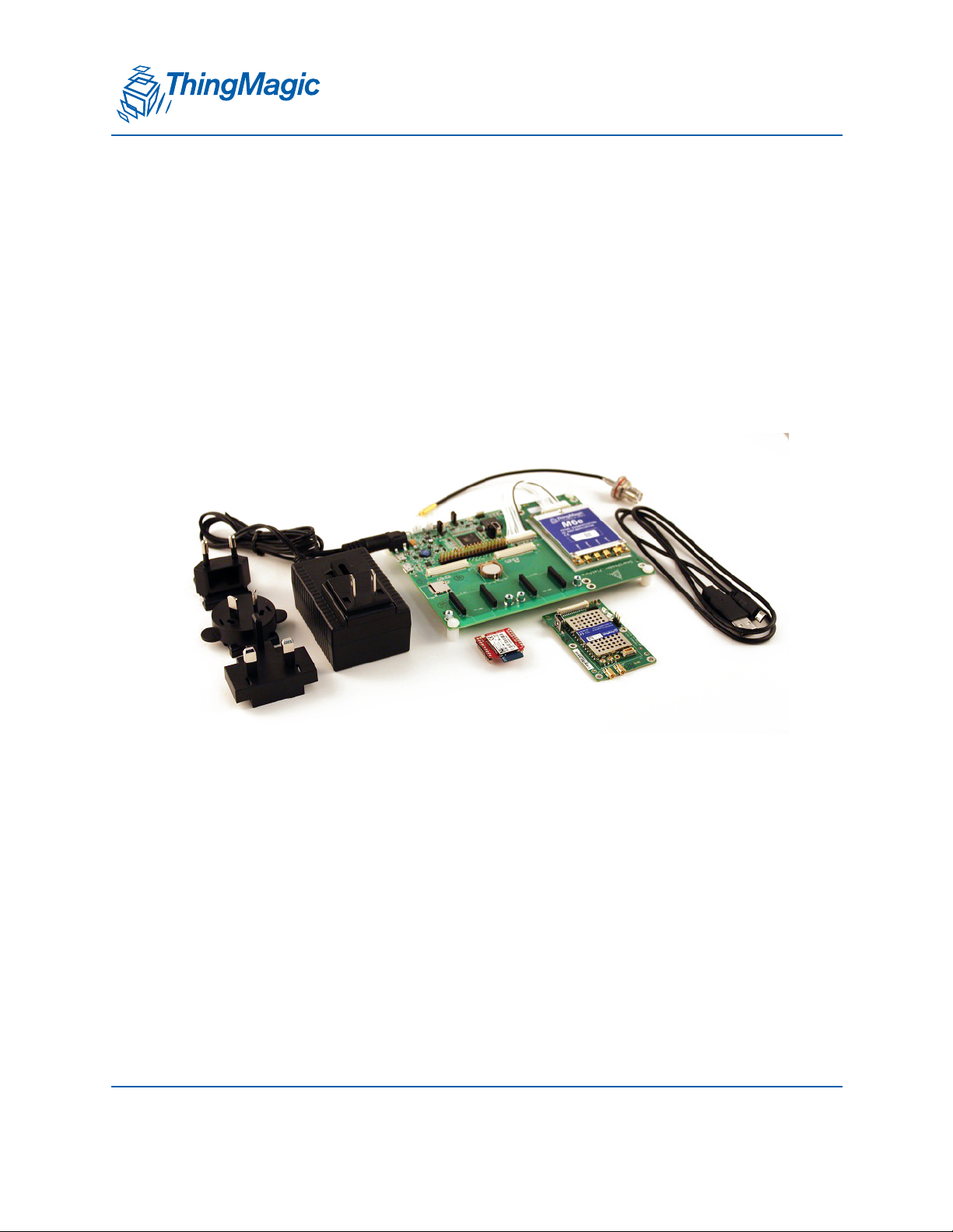
Hardware
xPRESS Platform Contents
Using the
Processor Motherboard with one module (either M6e, Micro, or Micro-LTE)
AC Power Adapter with international adapter plugs
Two USB cables
Antenna cable which converts MMCX to Reverse-TNC
The xPRESS Development Platform comes with an AC power adapter, two USB cables,
one antenna cable, and one of the UHF RFID modules shown in the picture. The red
18 Quick Start Guide
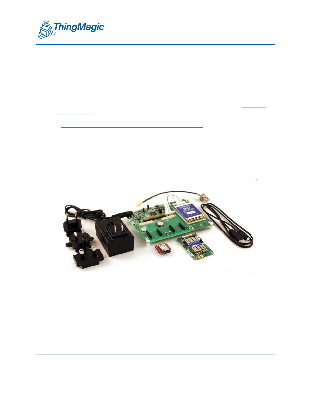
Page 19
xPRESS Platform Contents
A DIVISION OF TRIMBLE
Bluetooth module shown in the picture is optional. Here are all the optional interface and
sensor modules.
Additional components available from ThingMagic include:
Antennas
Reverse-TNC to Reverse-TNC cable
The xPRESS platform supports a coin-cell battery (to power a Real Time Clock) and
rechargeable Li-ION batteries, but these items are not currently available from
ThingMagic.
Software
All software is available to download from the ThingMagic Support site:
http://www.thingmagic.com/manuals-firmware
The xPRESS platform is shipped with a demonstration application pre-installed. This
application allows you to read RFID tags, optionally add GPS information to the data
received, and output the information via any of the supported interfaces. USB and
Bluetooth are supported without any modification to the application code. To use any
other optional modules, the xPRESS SDK will need to be imported into an Eclipse
development environment, minor changes made to the configurable values, the
application program recompiled (“built”), and the resulting binary file downloaded to the
xPRESS processor. Later, you may wish to make other changes to customize the
program’s behavior to better address your application requirements.
Quick Start Guide 19
Page 20

xPRESS Platform Contents
A DIVISION OF TRIMBLE
Documentation
All documentation is available to download from the ThingMagic support site using this
URL:
http://www.thingmagic.com/manuals-firmware
This site also offers hardware design documentation that will allow you to develop your
own processor board based on the xPRESS platform design: This documentation
includes:
Schematics
Layout files
Gerber files
Bill of Materials
Component Data Sheets
20 Quick Start Guide
Page 21
A DIVISION OF TRIMBLE
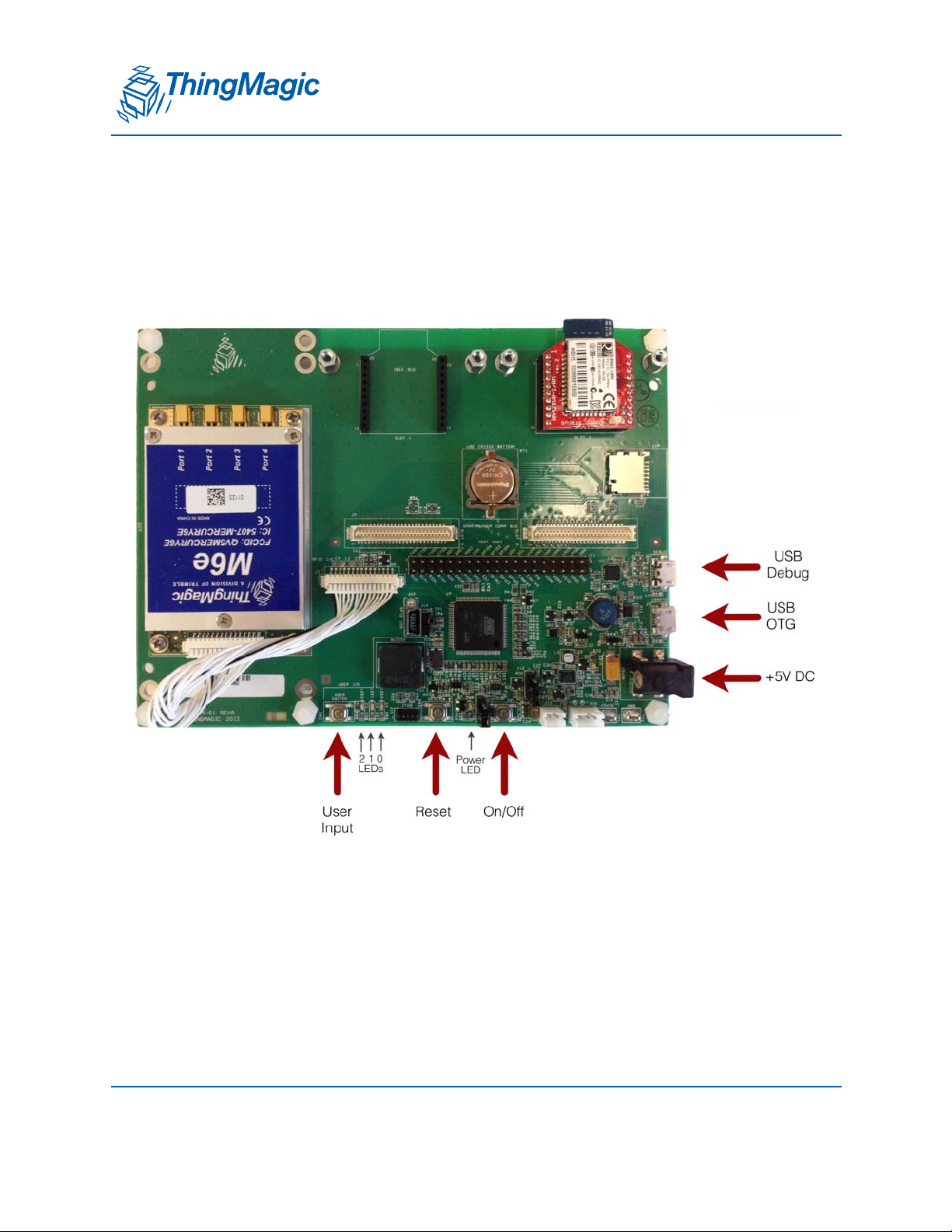
Hardware Setup
The main connectors and switches on the xPRESS motherboard are shown in the
diagram below. Your board may have a different RFID module than the M6e shown here.
Hardware Setup
The following steps will take you through the hardware set-up, power-up and connecting
the xPRESS platform using its pre-installed application which will read UHF RFID tags
and report them through the USB interface.
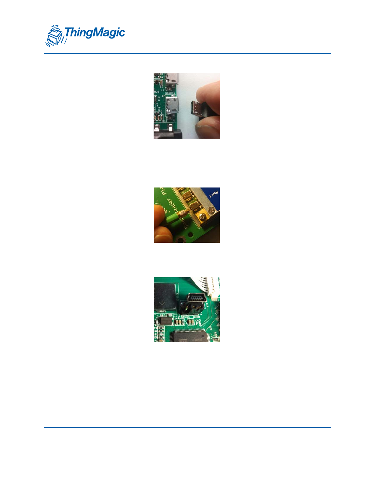
1. Connect the micro USB connector to the “USBOTG” port on the motherboard and the
other end to your Windows or LINUX PC.
Quick Start Guide 21
Page 22
Hardware Setup
A DIVISION OF TRIMBLE
2. Connect the supplied MMCX antenna cable to port 1 of the RFID module. Connect
your antenna to the other end of the cable (though an R-TNC to R-TNC cable if
necessary). Make sure all the antenna cable connections are tight.
3. Make sure the Flash Erase jumper is in the “NORM” position.
4. If you are using a Li-ion battery (not supplied with platform), plug it into the two- or
three-port jack, as appropriate.
22 Quick Start Guide
Page 23

Hardware Setup
A DIVISION OF TRIMBLE
5. Make sure the POE jumper is in the correct position for AC operation, as shown in the
photo below. Later, if powering the module from a POE module, you can move the
jumper into the “POE” position.
Always-on jumper.
Keep in this position
to use on/off switch
to start
POE jumper.
Keep in this position
to power via AC
adapter
6. Move the Always-on jumper to the position away from the board edge if you want the
board to be on whenever the power source is present. Otherwise, leave it in the
position closest to the board edge and use the on/off switch to control power to the
system.
7. Plug the AC adapter into the motherboard and connect it to an AC power source.
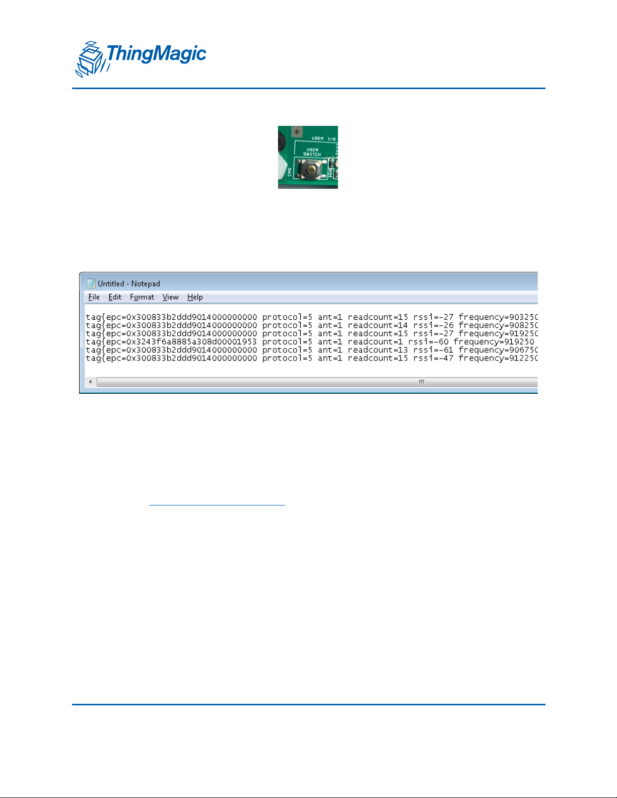
8. If you wish to run the pre-installed RFID Sensor application, move your PC cursor to
a database field or document where you would normally enter text via a keyboard.
9. Place one or more tags near the antenna and push the “User Switch” once.
Quick Start Guide 23
Page 24
Hardware Setup
A DIVISION OF TRIMBLE
10. Tags in the vicinity of the antenna will be read and “typed” on separate lines
repeatedly every second. All the tag “metadata” (information relating to tag reading
conditions) are included, as well as the tag identity (its “EPC”).
The blue LED will be on when the module is actively reading. The yellow LED will
flash and the buzzer will chirp whenever a tag is read.
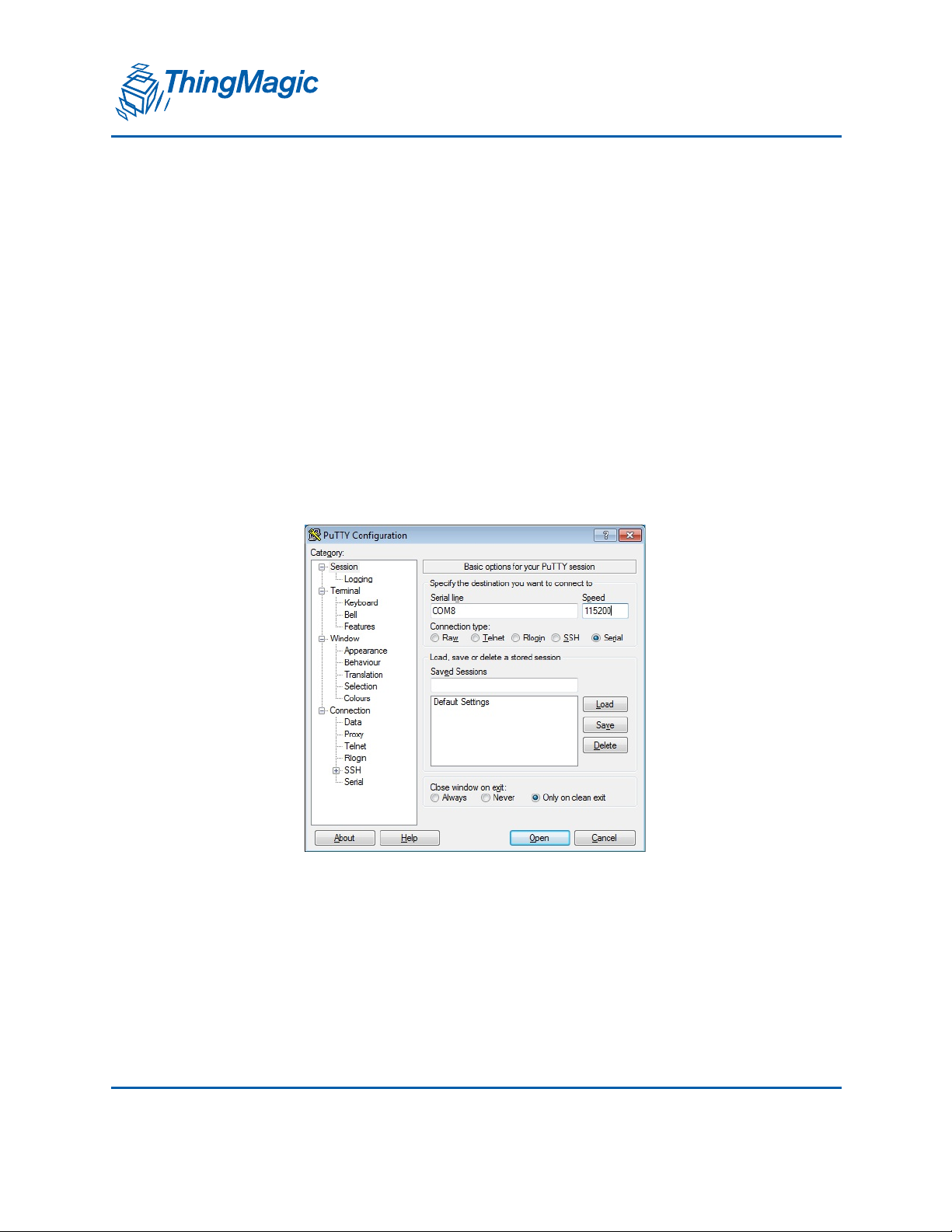
11. If you wish to see status messages while the xPRESS platform is operating, connect
the second USB cable into the “Debug” USB port and connect it to your PC. You will
need to activate a serial terminal application (such as puTTY) at 115200 bits per
second to view the messages. The guide to interacting with the console is found in
the
Using the Sample Application chapter.
12. Press the “User Switch” button again to stop reading
24 Quick Start Guide
Page 25

A DIVISION OF TRIMBLE
Using the Sample Application
Initially, only one sample application will be available for the xPRESS platform, the RFID
Sensor (an enhanced version of the original application that we called the “Keyboard
Wedge”. The xPRESS platform will ship with this application pre-installed and the source
code for it will be included in the SDK.
Basic instructions for operating this application were given in the Quick Start Guide. This
section provides additional information about its architecture how to interpret and control
the console messages seen while the xPRESS system is active.
Using the Sample Application 25
Page 26

RFID Sensor Application
A DIVISION OF TRIMBLE
RFID Sensor Application
The RFID Sensor is an application that reads tags in the vicinity of the antenna and
forwards their ID’s and environmental information to the active interface. If the active
interface is the USB port or Bluetooth port, they act as if they are a keyboard connected to
your host device and transfer the tag information just as if you were typing it. If either of
the network interfaces (WiFi or Ethernet) are the active interface, then they will stream
this same data using text-based IP protocols. Instructions for using the USB interface
were given in the
Optional Bluetooth, WiFi and Ethernet interfaces are explained in the
Modules Chapter.
Architecture of the RFID Sensor App
The RFID Sensor App is designed to get a user up and running with a minimum of effort. The
demonstration application simultaneously controls the RFID module, maintains the active data
interface, and forma ts the data that is sent out that interface.
Quick Start Guide Chapter. Setup, configuration, and operation of the
Using the Optional
We call this a “Sensor App” because it aggregates the information collected from the tag with
local information it knows about environmental conditions at the time the tag was read and
(optionally) the GPS location of the reader at the time the tag was read.
A console interface is provided which provides status information while the xPRESS platform is
operating and allows some interaction with the optional modules. Changing of configuration
settings are not supported through the console in this version of the application. Settings are
modified in the source code of the application, which is then re-built and downloaded to the
xPRESS platform.
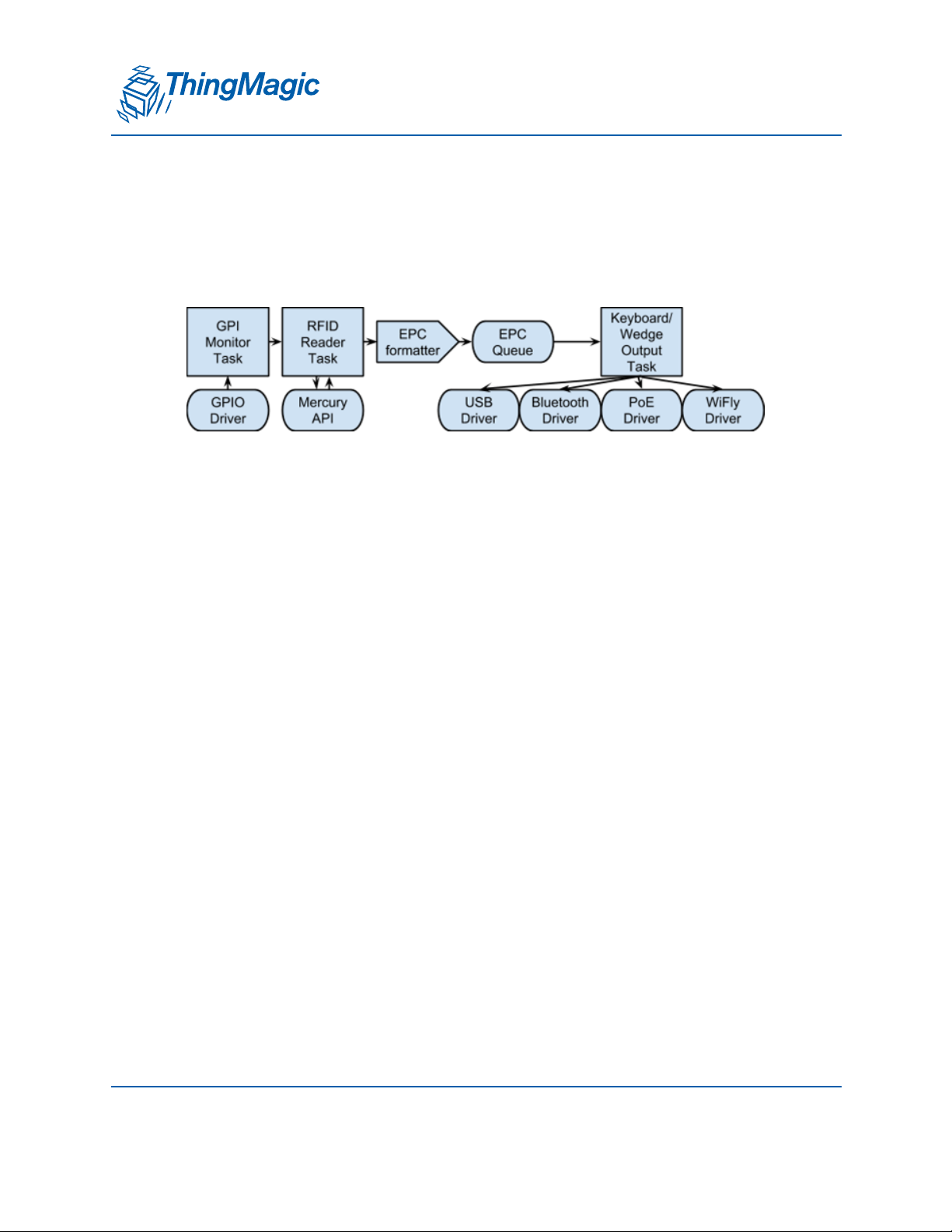
Demo App Architecture
The Demo App includes off-the-shelf software that provides a framework for it. These
include:
FreeRTOS: Provides tasks and queues
ASF: Provides drivers (except for Bluetooth module)
Mercury API: Provides control for the RFID module
The App itself consists of:
GPI monitor task
26 Using the Sample Application
Page 27
RFID Sensor Application
A DIVISION OF TRIMBLE
RFID reader task
Keyboard output task
EPC formatter function
Custom drivers: Bluetooth module
These functional utilities interact with each other as shown in the diagram below:
Demo App Program Flow
Execution starts at xpressReader/app_demo/main.c, which launches 2 tasks:
RfidReader and KBWedge.
Task RfidReader runs task_rfid, which controls the reader.
Task KBWedge runs task_wedge, which controls the UI (keyboard output,
pushbutton inputs).
The workflow begins when the user presses the read trigger button
pin_edge_handler fires on the falling edge of the button press, having previously
been set up by wedge_configure_buttons, which was called in task_wedge’s
initialization.
pin_edge_handler reads the current state of the read trigger button and sets the
global activateTagReads accordingly.
task_rfid monitors activateTagReads. When it becomes true, it enters readTags.
readTags operates the RFID reader then calls reportTags to retrieve the tag
reads.
reportTags fetches each tag read, formats it, then adds it to epcQueue
task_wedge constantly runs wedge_ui_process, which executes the state machine
that generates USB HID keyboard output. This has to be written as a state machine
because the USB host polls for one HID message at a time, and each HID message
corresponds to a single keypress (or release.) Note that only low-speed USB
connections do not poll automatically, so task_wedge’s inner loop only needs to run
in that case. For faster USB modes, the USB driver calls wedge_ui_process
directly.
Using the Sample Application 27
Page 28

RFID Sensor Application
A DIVISION OF TRIMBLE
Within wedge_ui_process is a call to xQueueReceive from epcQueue.
Whenever the current string is depleted, the state machine automatically
calls this function to get the next available tag read string.
Demo App Program Configuration
To modify the workflow, there are many compile-time switches in xpressreader/app/
conf/conf_xpress_reader.h:
To change which button is the trigger, modify all strings related to
PRODUCT_MAIN_BUTTON.
To change trigger behavior, change the ENABLE_GPI_READ definition.
ENABLE_GPI_READ_WHILE_PRESSED: Keep reading as long as trigger is held
down.
ENABLE_GPI_READ_ON_OFF: Toggle reading each time trigger is pulled.
ENABLE_GPI_READ_ONCE: Read once for each trigger pull.
To change tag read feedback
ENABLE_TAG_READ_BUZZER
ENABLE_TAG_READ_LEDS
To change the tag read output format
SIMPLE_TAG_EPC_OUTPUT
FULL_TAG_DATA_SINGLE_LINE_OUTPUT
FULL_TAG_DATA_FORM_OUTPUT
For finer-grained control, use the TAG_*_{PRE,POST}FIX macros
RTC: Real Time Clock
The xPRESS system has RTC block which is in-built to main controller and used to
append timestamp of tag read into Sensor output data format.
Due to hardware limitation of not having external 32kHz crystal (RTC will have to use
internal RC which won’t be as accurate), the user will need to set RTC date and time at
28 Using the Sample Application
Page 29

RFID Sensor Application
A DIVISION OF TRIMBLE
every power cycle using CLI command. otherwise timestamp will start from default RTC
value ie, 2007-01-01 in Sensor output tag data format.
tag{epc=0xdeadbeafdeadbeafdeadbeaf protocol=GEN2 ant=1 readcount=5
rssi=-79 frequency=926750 timestamp=2007-01-01T00:00:07.587 phase=2
gpio=1111 lat=17.260672 lon=78.236042 }
Using the Sample Application 29
Page 30
xPRESS Console
A DIVISION OF TRIMBLE
xPRESS Console
Connecting to the Console
The Console provides status information for the xPRESS platform. Some interactive utilities supported by
the FreeRTOS operating system and maintenance utilities for the optional modules are supported as well.
Follow these steps to view the Console:
1. Install the FTDI Virtual Com Port drivers for your OS:
http://www.ftdichip.com/Drivers/VCP.htm
2. Run a terminal program (such as PuTTY) and connect to the console (debug port) as
a serial connection at 115200 bps.
Console Commands
The console has a limited number of commands that it can interpret.
Here are the supported commands:
30 Using the Sample Application
Page 31

A DIVISION OF TRIMBLE
help
Lists all the registered commands
debug <value>
Expects one parameter 0 or 1
0 - OFF
1 - DEBUG
loglevel <value>
Expects one parameter 0-8
0 - OFF
1 - EMERG
2 - ALERT
xPRESS Console
3 - CRIT
4 - ERR
5 - WARNING
6 - NOTICE
7 - INFO
8 - DEBUG
peek <address>
Expects one parameter
poke <address> <32 bit data>
Expects two parameters
system-status
Displays a table showing the status of various parts of the system
task-stats
Displays a table showing the state of each FreeRTOS task
Using the Sample Application 31
Page 32

xPRESS Console
A DIVISION OF TRIMBLE
run-time-stats
Displays a table showing how much processing time each FreeRTOS task has used
echo-3-parameters <param1> <param2> <param3>
Expects three parameters, echos each in turn
echo-parameters <...>
Take variable number of parameters, echos each in turn
param-test
Parameter-parsing demo. Enter any number of unsigned integer arguments
var-params <param>: Parse arbitrarily long list of params
spi-test: Run canned SPI test
twi-probe [start] [end]
Find all connected TWI/I2C devices in the 8-bit address range [start,end]
(default=[0,0x80])
Note
I2C protocol analyzers see 0x78-0x7B as "unknown" 10-bit addresses, since
they start with the 10-bit address preamble (11110)
twi-read <chipaddr> <addr> <len>: Read TWI/I2C EEPROM
twi-write <chipaddr> <addr> <data>: Write TWI/I2C EEPROM
wiznet-spitest: Run SPI transfer rate test in POE module’s WIZnet W5500-
compatible mode
wiznet-dhcp: Run DHCP for POE module’s WIZnet W5500
wiznet-test: Run canned POE modules’s WIZnet W5500 test
wifly-get-net-info: Display the WiFi module network details
wifly-get-mac: Display the WiFi module MAC address
wifly-factory-reset: Reset the WiFi module’s configuration settings to the factory
defaults
wifly-firmware-update: WiFi module firmware update via FTP
rtc-datetime: <GET> / <SET> <mm> <dd> <yyyy> <ww> <HH> <MM> <SS>
To get/set Real-Time-Clock date and time
32 Using the Sample Application
Page 33

xPRESS Console
A DIVISION OF TRIMBLE
Log and Debug Levels
As more modules have been added, each with its own complement of debug messages,
the output of the console has become more complex and potentially confusing. To reduce
the message volume, we have added the ability to suppress less important messages.
This suppression can be done at run-time, via log level controls, or by altering the code
that produces the messages.
Run-time Controls
For debug console messages, we have introduced the CLI command loglevel <value>
loglevel 0 (LOG_OFF: debugging output is disabled)
loglevel 1 (LOG_EMERG: messages that indicate the system is unusable)
loglevel 2 (LOG_ALERT: messages that indicate action must be taken immediately)
loglevel 3 (LOG_CRIT: messages that indicate critical conditions)
loglevel 4 (LOG_ERR: messages that indicate error conditions)
loglevel 5 (LOG_WARNING: messages that indicate warning conditions)
loglevel 6 (LOG_NOTICE: messages that indicate normal conditions)
loglevel 7 (LOG_INFO: informational messages )
loglevel 8 (LOG_DEBUG: debug-level messages)
Note
Selection of a log level enables messages for that level and all more critical
messages (lower numerical value)
The previous CLI command debug <on/off> is also supported to maintain backward
compatibility. It maps into the new loglevel command as follows:
debug 1 means loglevel 8
debug 0 means loglevel 0
Note
It is not necessary to complete the CLI command on one line when the
console is sending status messages at the same time. However, you must
complete the command without error. If you make an error in typing, hit the
Using the Sample Application 33
Page 34

xPRESS Console
A DIVISION OF TRIMBLE
<Enter> key and start again. The backspace key does not erase previously
typed characters.
34 Using the Sample Application
Page 35

A DIVISION OF TRIMBLE
Using the Optional Modules
This chapter will take you through the hardware installation, software configuration and
operation of the optional modules for the xPRESS platform . There is also a common
section on GPI management interaction among the modules.
Where necessary, separate instructions are provided for setting up the xPRESS modules
for use with Windows, Linux, and Android hosts.
Optional Modules currently supported by the xPRESS platform include:
Bluetooth Module
WiFi Module
Power-Over-Ethernet Module
GPS Module
Using the Optional Modules 35
Page 36

A DIVISION OF TRIMBLE
Bluetooth Module
Bluetooth Module
Specifications
The optional Bluetooth module is a Roving Networks (now owned by Microchip.com) RN42XV. It can be ordered from ThingMagic as part number XP-BT.
The full data sheet may be obtained here:
http://ww1.microchip.com/downloads/en/DeviceDoc/RN41XV-RN42XV-ds-v1.0r.pdf
Hardware Installation
1. Disconnect power from the xPress motherboard and insert the Bluetooth module into
one of the two xBee sockets on the motherboard. Make sure the antenna is pointed
toward the board edge, as shown below.
36 Using the Optional Modules
Page 37

Bluetooth Module
A DIVISION OF TRIMBLE
2. Before starting, make sure the the RN-42 Bluetooth module is in its discoverable
mode -- its green light must be blinking slowly (once per second.)
If this LED is solid green, the module is already connected to a host. You must break
the connection (usually by “removing” the device from the host’s list of Bluetooth
devices) if you want to pair with a new host.
If it is blinking rapidly, the module is in command mode. Try rebooting the xPRESS
motherboard to reset the Bluetooth module.
Linux Bluetooth Keyboard Setup
For Linux (Such as Ubuntu 10.04LTS),
1. Plug in your Bluetooth adapter, if it’s not built in to your PC.
2. Install blueman. (Replaces the stock Bluetooth manager.)
sudo apt-get install blueman
3. Log out and log back in again to get Blueman to install its icon into the menu bar.
4. Look for the Bluetooth icon at the upper-right of your screen:
There will probably be two: one for the stock Bluetooth client, and one for blueman.
Blueman’s icon will say Bluetooth Enabled when you hover over it.
Using the Optional Modules 37
Page 38

A DIVISION OF TRIMBLE
5. Click once to open a Bluetooth Devices window.
Bluetooth Module
6. Click Search
When the Bluetooth device window a ppears, right-click on the Bluetooth address.
38 Using the Optional Modules
Page 39

A DIVISION OF TRIMBLE
Bluetooth Module
7. Select Pair
If the pairing activity bar does not stop on its own, just keep going.
Using the Optional Modules 39
Page 40

Bluetooth Module
A DIVISION OF TRIMBLE
8. Right-click again and wait for the Connect To: menu to appear. Select Input
Service
.
9. When the colored bar graph appears, you’re ready! You should also see a solid light
on the Bluetooth module instead of blinking.
10. Whenever the connection is broken, the Bluetooth module will automatically attempt
to reconnect. If you get a re-connection prompt, click Grant to restore the
connection. To automatically grant permission in the future, check Always grant
access
40 Using the Optional Modules
Page 41

Bluetooth Module
A DIVISION OF TRIMBLE
first.
11. To permanently unpair a Bluetooth module, go back to the Blueman window, right-
click on the device, and select “Remove...“. You should not have to do this unless
you wish to pair the Bluetooth module with a different host.
Windows Bluetooth Keyboard Setup
1. Right-click the Bluetooth icon in the Windows notification area (at lower right.)
2. If you have no Bluetooth icon, go to Start / [Control Panel] / Devices and Printers
3. Select Add a Device
4. Wait for the device to appear. The name will probably be RNBT-nnnn, where nnnn
is the last 4 digits of the module’s Bluetooth MAC address.
5. Right-click the device and select Properties. Wait for the list of Bluetooth services to
appear. Check Drivers for keyboard, mice, etc (HID) and press OK. (NOTE: This
method tends to be more reliable than selecting the device and pressing Next. That
method seems to be hard-coded to a routine that always asks you to enter a code on
the peripheral device. The RN-42 doesn’t really support this.)
6. Wait for drivers to install.
7. Dismiss the success message, and you should see a request to connect. A
Bluetooth device is trying to connect. Click to allow this. Click on this
notification.
8. Click Next in the Finish connection to this device dialog that appears.
Using the Optional Modules 41
Page 42

Bluetooth Module
A DIVISION OF TRIMBLE
9. Click Close in This device has been successfully added to this computer. You
are now connected! There should be a solid green light on the RN-42 Bluetooth
module.
In the future, you should not have to confirm anything. Whenever the connection is lost,
the RN-42 will automatically try to reconnect. Windows will remember that you allowed
the connection and silently reattach.
Android (4.2) Bluetooth Keyboard Setup
These instructions have been tested on Android 4.2.2 running on a Nexus 7 tablet. Earlier
versions will probably require additional steps, possibly involving third-party software.
For Android 4.2 (1st-generation Nexus 7 circa July 2013)
1. Open Bluetooth settings
2. Swipe down from the upper-right corner of the screen. Click BLUETOOTH
3. Pair with the Bluetooth module
Click SEARCH FOR DEVICES
Under AVAILABLE DEVICES at the bottom, look for a device with the name
RNBT-nnnn, where nnnn is the last 4 digits of the module’s Bluetooth
MAC address.
Click on the device and wait for it to become Connected.
4. Use the Bluetooth device as a virtual keyboard
Go to a text entry field. (For example, use the Fast Notepad app and Add a new
note.)
Start the RFID Sensor application. Tag read data should appear in your text field.
You may wish to simultaneously use a virtual keyboard with the RFID Sensor. By default,
the Bluetooth RFID Sensor disables the virtual on-screen keyboard. This is normal when
adding full physical keyboards, but not for our RFID Sensor. To allow concurrent use of
the Bluetooth Sensor and an on-screen keyboard, follow these steps:
1. Swipe down from the upper-left of the screen to open the Notifications panel
2. Select Choose input method
3. Turn OFF the switch for Hardware: Physical keyboard
42 Using the Optional Modules
Page 43

Bluetooth Module
A DIVISION OF TRIMBLE
Note that this does not disable the Bluetooth keyboard, it merely prevents it from
suppressing the on-screen keyboard.
4. Click the back button to dismiss the input method panel
Now the on-screen keyboard will appear when you enter the text field.
You can also activate the xPRESS RFID Sensor, and it will still type in tag data.
!
CAUTION!
!
If you have the on-screen keyboard popped up while the RFID Sensor is
typing, it will activate any auto-completion features, as if you had typed
on the on-screen keyboard. This can be slow, so dismiss the on-screen
keyboard if you have a lot of data coming from the Sensor.
RFID Sensor Demo Instructions
1. Make sure there is no USB cable connected to the “USBOTG” interface. It is OK if a
cable is connected to the DEBUG (Console) interface. After pairing, the xPRESS
platform will identify itself as a keyboard to the host. Wait for the host to recognize the
interface as an HID device.
2. Open a host application that can accept text
Press the “User Switch” button to start reading.
The RFID Sensor application automatically adjusts the module RF output levels. If
powered by USB or battery, the module will be set to +20 dBm. If powered by AC or
POE, the module will be set to +30 dBm.
The blue LED will be on whenever the module is reading.
3. The yellow LED will flash and the buzzer will chirp whenever a tag is found. If the tag
buffer becomes backed up, reading will slow down (this is common when the
Bluetooth module is used as its interface speed as an HID device is considerably
slower than the USB connection).
Using the Optional Modules 43
Page 44

Bluetooth Module
A DIVISION OF TRIMBLE
4. The EPC and metadata being typed to the host computer will look like the screen
capture below, with each informational element preceded by a label and equals (=)
sign.
5. Press the User Switch button again to stop reading
Bluetooth Module Command Interface
The following information is relevant if you change the demonstration application’s
initialization process for the Bluetooth module in order to put it in a different mode of
operation.
RN-42 Initialization
To reset the RN-42 Bluetooth module into HID mode,
Assumes a freshly powered-up module (i.e., just power-cycled the entire xPRESS
Reader)
Connect on UART at 115200bps, 8N1
Send "$$$"
Enter command mode. Can’t be in the middle of a data stream -- has to be by
itself within a “1 second window”) DO NOT add any newline characters
Wait for "CMD\r\n"
Send "S~,6\n"
Set module profile to HID mode
Wait for "AOK\r\n"
Send "R,1\n"
Reboot
44 Using the Optional Modules
Page 45

Bluetooth Module
A DIVISION OF TRIMBLE
Wait for "Reboot!\r\n%REBOOT"
RN-42 Flow Control
If data is sent faster than the channel can keep up, the RN-42 has hardware flow control
to prevent buffer overflow.
According to the RN-41/RN-42 datasheet,
UART_RTS, goes high to disable host transmitter
So the application should monitor the state of the RN-42’s UART_RTS pin and hold off
when it goes high.
Conversely, the RN-42 listens on UART_CTS. If you set it high, the RN-42 will refrain
from transmitting further.
RN-42 Connection Status
The RN-42 sets Pin GPIO2 high when it is connected to another Bluetooth device. This is
important because it means you should not try to send commands to its UART. If
connected, any text you send will pass straight through to the Bluetooth device on the
other side.
If GPIO2 is not connected to the system, you can try sending the command mode escape
sequence ("$$$" embedded in 1 second of silence.) If the module responds "CMD\r\n",
you have successfully entered command mode (therefore the module is not connected to
another Bluetooth device.) If you don’t get the expected response, the module is
connected, and we have sent a spurious "$$$", but that’s still better than sending an
entire sequence of commands.
Using the Optional Modules 45
Page 46

A DIVISION OF TRIMBLE
WiFi Module
WiFi Module
The optional WiFi module is an XBee-format module with an integrated antenna an “AT
Command” style interface. The part number is RN171XVW-I/RM. It may be ordered from
Thingmagic as part number XP-WI-FI.
WiFi transport will be used as the output interface only if neither USB, Bluetooth or PoE
are active (unless you modify the application program to use different logic).
To enable the WiFi output interface, the user may need to modify conf_xpress_reader.h
to disable other modules which are using the same XBee slot. The required modifications
in conf_xpress_reader.h are
1. Enable WiFi output interface by un-commenting
#define ENABLE_OUTPUT_WIFLY. (It is un-commented by default)
2. Define the UART interface to be used for WiFi module using WIFLY_DEVNAME and
this depends on XBee slot being used for WiFi module (e.g.,
WIFLY_DEVNAME "/USART1" )
#define
Slot - 0 is used with USART1 (This is the default)
Slot - 1 is used with USART2
3. If they are present, disable other modules which are using the same UART defined in
above step.
46 Using the Optional Modules
Page 47

WiFi Module
A DIVISION OF TRIMBLE
If the Bluetooth module is present, check for BLUETOOTH_DEVNAME and
comment out “
#define ENABLE_OUTPUT_BT”
If the GPS module is present, check for GPS_DEVNAME and comment out
“
#define confINCLUDE_GPS”. Because the GPS module does not interfer
with the WiFi module’s use as a data interface, you may want to keep it
enabled to augment tag-read information with GPS information.
The LED displays on the module indicate the following states for the module:
Green LED D1 is on when there is a connection to an access point
Yellow LED D2 flashes whenever the xPRESS platform communicates with the
module.
Red LED D3 is on when there is a TCP connection through which tag information can
be transferred.
Information about the network connection can be obtained through the console interface
by entering the command: wifly-get-net-info
Typical output is shown here (for the WiFi module acting as a TCP client):
**************************
WIFLY: Network Info ******
**************************
IF=UP
DHCP=ON
IP=192.168.11.54:49152
NM=255.255.255.0
GW=192.168.11.1
HOST=10.8.80.79:7777
PROTO=TCP,
Using the Optional Modules 47
Page 48

WiFi Module
A DIVISION OF TRIMBLE
Features Implemented
The WiFi module supports several transport configurations. The configuration can be
changed by having the application program send the appropriate commands to the WiFi
module over its UART interface.
TCP client only
TCP server and TCP client
UDP client
HTTP client
Note
The sample application does not support the module’s Secure Mode which
forces the module to only receive packets only from an IP address that
matches the stored host IP.
Default configuration is “TCP server and TCP client”. In this mode xPress behaves as
both TCP server and TCP client.
To change the mode, access point information, Server IP details, etc, it is necessary to
modify the configuration settings in the code (app_demo\conf\conf_wifly.h) and
recompile the application.
Also edit WIFLY_CONFIG_FILE with an appropriate new filename If any configuration
settings are modified.
config filename format: "config_mmddyyyyhhmm"
This should start with
!
CAUTION!
config_ and remaining part would be any new string.
!
If the configuration filename in the application program is not changed,
any setting changes made at the same time will be ignored.
Following table provides the features supported and their configuration details.
Feature Configuration
Parameter
Default Value Remarks
48 Using the Optional Modules
Page 49

A DIVISION OF TRIMBLE
WiFi Module
AP
Configuration
DHCP Mode
Static IP
(xPRESS)
WIFLY_WLAN_SSID "Tenda"
WIFLY_WLAN_AUTH WIFLY_AUTH_MODE_WPA2PSK
WIFLY_WLAN_PASSPHRASE "Qss rfid@14" Required for Auth type = WPA
WIFLY_WLAN_WEP_KEY_NUMBE
R
WIFLY_WLAN_WEP_KEY "112233445566778899AABBCCDD" Required for Auth type = WEP
WIFLY_DHCP_MODE WIFLY_DHCP_ON if set to WIFLY_DHCP_ON , need to get
WIFLY_MODULE_IP_ADDRESS "192.168.0.100" Required if WIFLY_DHP_OFF
WIFLY_LOCAL_PORT_NUMBER 49152 since this port number may increment at
WIFLY_SUBNET_MASK "255.255.255.0" Required if WIFLY_DHCP_OFF
1 Required for Auth type = WEP
xPRESS module IP from the debug
console logs.
run time, see debug logs.
The best practice is to use port number
within the range assigned for "Dynamic,
private or ephemeral ports". http://
en.wikipedia.org/wiki/Wellknown_ports#Dynamic.2C_private_or_e
phemeral_ports
Host
Configuration
TCP server
and client
TCP client
only
UDP client
WIFLY_GATEWAY_ADDRESS "192.168.0.1" Required if WIFLY_DHCP_OFF
WIFLY_REMOTE_HOST_IP_ADDR
ESS
WIFLY_REMOTE_HOST_PORT_N
UMBER
WIFLY_IP_MODE WIFLY_TCP_SERVER_CLIENT
WIFLY_IP_MODE WIFLY_TCP_SERVER_CLIENT change to
WIFLY_IP_MODE WIFLY_TCP_SERVER_CLIENT change to WIFLY_UDP
"192.168.0.121" Modify to use your host where TCP
server/client or UDP server is running
60001 Modify to use your host where TCP
server/client or UDP server is running.
The best practice is to use port number
within the range assigned for "Dynamic,
private or ephemeral ports". http://
en.wikipedia.org/wiki/Wellknown_ports#Dynamic.2C_private_or_e
phemeral_port
s
change to
WIFLY_TCP_SERVER_CLIENT
WIFLY_TCP_SERVER_CLIENT or
WIFLY_TCP_CLIENT
Using the Optional Modules 49
Page 50

A DIVISION OF TRIMBLE
WiFi Module
HTTP client
CLI
commands
added
Flow control
Power
Management
WIFLY_IP_MODE WIFLY_TCP_SERVER_CLIENT change to
WIFLY_TCP_SERVER_CLIENT +
WIFLY_HTTP_CLIENT
WIFLY_DNS_NAME www.posttestserver.com HTTP web server name
WIFLY_HTTP_SERVER_DIR xpr Directory name in HTTP web server.
Tags will be available in this directory.
ex: http://posttestserver.com/data/2014/
06/18/xpr/
WIFLY_HTTP_CONTENT_TYPE_F
ORM_URLENCODED
N/A N/A command: wifly-get-mac
N/A N/A command: wifly-factory-reset
N/A N/A command: wifly-firmware-update
N/A N/A command: wifly-get-net-info
N/A N/A
WIFLY_WLAN_TRANSMIT_POWE
R
WIFLY_TCP_AUTO_CONNECT_TI
MER
N/A HTTP Data Formatter type
1. Flow control is enable
2. Baud rate = 230400
12 dBm
2 To connect host TCP/HTTP
automatically every 2 sec
WIFLY_TCP_IDLE_TIMER 60 sec
WIFLY_TCP_SLEEP_TIMER 60 sec
WIFLY_TCP_WAKE_TIMER 30 sec
Initialization Process
RN-171 initialization will be done only if other high priority interfaces (USB, BT and PoE)
are not successful.
WIFLY_init() is called from init_output() as part of task_Wedge task initialization.
WIFLY_init() will configure the serial interface for RN-171 and also initializes all
configurable parameter variables with configuration defines/values.
The serial interface for RN-171 is configured in WIFLY_init_serial_interface()
50 Using the Optional Modules
Page 51

WiFi Module
A DIVISION OF TRIMBLE
After WIFLY_init(), init_output() calls WIFLY_join() to initialize the RN-171 by
sending a sequence of ASCII commands.
a. WIFLY_setupWlan() sets the wlan settings like SSID, Auth type and Password
b. WIFLY_setupIP() sets the DHCP mode and, if DHCP is configured as OFF, it
also sets Static IP settings like IP address, Netmask, Gateway and DNS
address.
c. WIFLY_setupProtocol() sets the protocol mode and also sets the remote host
settings which includes DNS lookup for obtaining the host IP address using
hostname.
d. WIFLY_setupWlanLinkmonitor() sets the link monitor timeout threshold which
represents the number of failed scans before the RN-171 declares a Lost-AP
state and de-authenticates. It also sets the RSSI threshold level.
e. WIFLY_setupTCPperformance() sets the flush timer and flush size. These are
used for optimizing the TCP performance where flush is used to minimize
latency and TCP/IP overhead and flush timer may be assigned a large
number to avoid fragmentation.
f. WIFLY_setupMonitorGPIO() sets the GPIO pins configuration to use for
monitoring functionality.
g. WIFLY_setupPowerManagement() sets the power management related
configuration. It configures transmit power, auto connect timer, idle timer,
sleep timer and wake up timer.
h. WIFLY_setupFlowControl() sets the flow control enable and changes the baud
rate from the default baud rate ie, 9600. At lower baud rates (less than 115K),
the system can send data over TCP/IP without flow control.
i. WIFLY_setupAssociate() sets the join policy as “automatic” and then tries to join
with the stored network AP.
Using the Optional Modules 51
Page 52

WiFi Module
A DIVISION OF TRIMBLE
Connection Status
RN-171 uses GPIO pins to monitor the status of association/connection and to control the
connection as below.
Signal Name Direction Function
GPIO4 Output This pin goes high after the module has associated/authenticated and has
an IP address.
GPIO5 Input Set this pin high to trigger a TCP connection and low to disconnect.
GPIO6 Output This pin goes high when the module is connected over TCP and low
when disconnected.
xPRESS Reader uses GPIO4 and GPIO6 pins to monitor the status of association and
connection in function WIFLY_MonitorWiflyStatus() which will be called by the task
task_Wedge.
Note
GPIO5 is not used as this pin is NC on xPRESS Reader
Power Management
RN-171 has the power features shown below:
52 Using the Optional Modules
Page 53

A DIVISION OF TRIMBLE
Feature Value(s) xPRESS Support
WiFi Module
Output
Power
Sleep mode 4 uA RN-171 will go to sleep mode based on Idle timer and
RX mode 35 mA N/A
TX mode 185 mA
Sleep Mode: RN-171 will go into sleep mode upon expiration of the sleep timer which
can start upon expiration of the idle timer. It is used to disconnect TCP automatically
when there is no data activity.
The settings for sleep timer and idle timer are configurable using config parameters.
Wakeup Mode: RN-171 will wake up when tag reader button is pressed or when the
Wakeup timer expires. Upon wakeup, RN-171 tries to join the network and connects to
server over configured protocol. If wakeup is due to tag reader button press, the RN-171
sends the tag data after the connection is re-established.
1 - 12 dBm Provides configuration parameter to set transmit
power between 1 and 12 dBm
Sleep timer values in seconds.
Provided configuration parameters for Idle timer and
Sleep timer values.
Depends on transmit power setting (see above)
@maxium power ie, 12 dBm
Console Command Control
The Console commands are configured in conf_xpress_reader.h
confINCLUDE_CLI_CMD_WIFLY_GET_NET_INFO
This is used to activate Console commands to get network information from the RN171
The Console command’s syntax: wifly-get-net-info
confINCLUDE_CLI_CMD_WIFLY_GET_MAC
This is used to activate the Console command to get MAC address of the RN-171
The Console command’s syntax: wifly-get-mac
Using the Optional Modules 53
Page 54

A DIVISION OF TRIMBLE
confINCLUDE_CLI_CMD_WIFLY_FACTORY_RESET
This is used to include the Console command for RN-171 factory reset
The CLI commands syntax: wifly-factory-reset
confINCLUDE_CLI_CMD_WIFLY_FIRMWARE_UPDATE
This is used to include the Console command to update firmware in the RN-171
The CLI commands syntax: wifly-firmware-update <filename>
<filename> type is .mif or .img
Configuration Settings
To use RN-171 with xPRESS Reader, enable configuration for output mechanism in
conf_xpress_reader.h as ENABLE_OUTPUT_WIFLY
WiFi Module
The WiFi module (RN-171) requires the following configuration settings to support all its
modes of operation.
WiFi Config
SSID
Auth type
Password
DHCP/Static IP Config
DHCP Mode ON/OFF
Port Number
IP Address
Netmask
Gateway
DNS Address
Remote/Host Config
Hostname / DNS name
Host IP Address
54 Using the Optional Modules
Page 55

WiFi Module
A DIVISION OF TRIMBLE
Host Port Number
Protocol Mode
Protocolmode
Note
The best practice is to select port numbers for module and host within the
range assigned for "Dynamic, private or ephemeral ports".
49152 - 65535 are dynamic or private ports that cannot be registered with IANA.
This range is used for custom or temporary purposes and for automatic
allocation of ephemeral ports.
Reference:
http://en.wikipedia.org/wiki/Well-known_ports#Dynamic.2C_private_or_ephemeral_ports
Mapping of RN-171 Config. Parameters to xPRESS Names
If you use the documentation for the RN-171 module to determine what configuration
settings are supported, the following tables will help you to translate those interface
commands with the xPRESS demonstration program names.
Configuration category and
Command
WLAN - Setup WLAN Properties
set opt replace <char> WIFLY_WLAN_SPACE_REPLACEMENT_
CHAR
set wlan ssid <string> WIFLY_WLAN_SSID
set wlan auth <value> WIFLY_WLAN_AUTH
set wlan phrase <string> WIFLY_WLAN_PASSPHRASE
set wlan number <value> WIFLY_WLAN_WEP_KEY_NUMBER
set wlan key <value> WIFLY_WLAN_WEP_KEY
xPRESS Config Parameter
Name
Using the Optional Modules 55
Page 56

A DIVISION OF TRIMBLE
set wlan linkmon <value> WIFLY_JOIN_LINKMON_VALUE
set opt signal <value> WIFLY_JOIN_RSSI_VALUE
set wlan tx <value> WIFLY_WLAN_TRANSMIT_POWER
IP - Setup IP Properties
set ip dhcp <value> WIFLY_DHCP_MODE
set ip localport <value> WIFLY_LOCAL_PORT_NUMBER
set ip address <address> WIFLY_MODULE_IP_ADDRESS
set ip netmask <address> WIFLY_SUBNET_MASK
set ip gateway <address> WIFLY_GATEWAY_ADDRESS
set dns address <address> WIFLY_DNS_ADDRESS
set ip protocol <flag> WIFLY_IP_MODE
set ip host <address> WIFLY_REMOTE_HOST_IP_ADDRESS
set ip remote <value> WIFLY_REMOTE_HOST_PORT_NUMBER
set ip flags <mask> WIFLY_IP_FLAGS_MASK
COMM/UART - COMM and UART
Parameters
set comm idle <value> WIFLY_TCP_IDLE_TIMER
set comm size <value> WIFLY_FLUSH_SIZE
WiFi Module
set comm time <value> WIFLY_FLUSH_TIMER_VALUE_MS
set uart instant <value> WIFLY_UART_BAUDRATE_HIGH
set uart mode <mask> WIFLY_UART_MODE_VALUE
UDP - Sending data using UDP
set wlan ssid <string> WIFLY_WLAN_SSID
set wlan phrase <string> WIFLY_WLAN_PASSPHRASE
set ip protocol <flag> WIFLY_IP_MODE
set ip host <address> WIFLY_REMOTE_HOST_IP_ADDRESS
set ip remote <value> WIFLY_REMOTE_HOST_PORT_NUMBER
set ip localport <value> WIFLY_LOCAL_PORT_NUMBER
UDP - UDP Auto Pairing
set ip host <address> WIFLY_REMOTE_HOST_IP_ADDRESS
set ip flags <mask> WIFLY_IP_FLAGS_MASK
UDP - UDP Retry
set ip flags <mask> WIFLY_IP_FLAGS_MASK
56 Using the Optional Modules
Page 57

A DIVISION OF TRIMBLE
UDP - UDP Broadcast
WiFi Module
set broadcast address
WIFLY_UDP_BROADCAST_ADDRESS
<address>
set broadcast port <value> WIFLY_UDP_BROADCAST_PORT_NUMBER
set broadcast interval <mask> WIFLY_UDP_BRAODCAST_INTERVAL
Associate with an Access Point
set wlan ssid <string> WIFLY_WLAN_SSID
set wlan phrase <string> WIFLY_WLAN_PASSPHRASE
set wlan key <value> WIFLY_WLAN_WEP_KEY
set wlan number <value> WIFLY_WLAN_WEP_KEY_NUMBER
set wlan auth <value> WIFLY_WLAN_AUTH
Joining Networks
set wlan join <value> Automated. set as 1 = Try to associate with the access point that
matches the stored SSID, pass key, and channel. If the channel is
set to 0, the module will scan for the access point.
set wlan linkmon <value> WIFLY_JOIN_LINKMON_VALUE
Making Connection - Automatic
set ip host <address> WIFLY_REMOTE_HOST_IP_ADDRESS
set ip remote <value> WIFLY_REMOTE_HOST_PORT_NUMBER
set sys autoconn <value> WIFLY_TCP_AUTO_CONNECT_TIMER
set comm idle <value> WIFLY_TCP_IDLE_TIMER
set sys sleep <value> WIFLY_TCP_SLEEP_TIMER
set uart mode <mask> WIFLY_UART_MODE_VALUE
Making Connection - Using DNS
Settings
Using the Optional Modules 57
Page 58

A DIVISION OF TRIMBLE
set dns name <string> WIFLY_REMOTE_HOST_NAME
lookup <string> WIFLY_REMOTE_HOST_NAME
Making Connection - Using Backup
Addresses
set dns backup <string> WIFLY_DNS_NAME_BACKUP
HTML - Retrieve Web Server Data
set ip protocol <flag> WIFLY_IP_MODE
set dns name <string> WIFLY_REMOTE_HOST_NAME
set ip address <address> WIFLY_MODULE_IP_ADDRESS
set ip remote <value> WIFLY_REMOTE_HOST_PORT_NUMBER
HTML - HTML Client / Web Server
Modes
set opt format <flag> WIFLY_HTTP_FORMAT_VALUE
WiFi Module
HTML - Connect to a Web Server
Automatically
set sys autoconn <value> WIFLY_TCP_AUTO_CONNECT_TIMER
HTML - Connect to a Web Server
Automatically when UART Data Is
Received
set uart mode <mask> WIFLY_UART_MODE_VALUE
HTML - Post Binary Data
set opt format <flag> WIFLY_HTTP_FORMAT_VALUE
HTML - Post Sensor Data
Automatically
set sys autoconn <value> WIFLY_TCP_AUTO_CONNECT_TIMER
set opt format <flag> WIFLY_HTTP_FORMAT_VALUE
FTP - Upgrading Firmware via FTP
set ftp user <string> WIFLY_FTP_SERVER_USER
58 Using the Optional Modules
Page 59

A DIVISION OF TRIMBLE
set ftp pass <string> WIFLY_FTP_SERVER_PASSWORD
set ftp dir <string> WIFLY_FTP_SERVER_DIR
FTP - Connect to an FTP Server
set ftp dir <string> WIFLY_FTP_SERVER_DIR
set ftp user <string> WIFLY_FTP_SERVER_USER
set ftp pass <string> WIFLY_FTP_SERVER_PASSWORD
Other Commands
set sys autosleep <value> WIFLY_TCP_SLEEP_TIMER
WiFi Module
Known Limitations
1. Currently, the default interface depends on the slot in which the module is installed
and is either USART1 (slot 0) or USART2 (slot 1)
WIFLY_DEVNAME is set to use USART1 or USART2
Disable other interfaces in code if using same USART
2. Currently baud rate works up to 230400 and by default it is configured as 230400
Known Issues
1. WiFly module wakeup from its sleep is not as per configuration setting
(WIFLY_TCP_WAKE_TIMER)
WiFly module goes to sleep mode depending on values defined for
WIFLY_TCP_IDLE_TIMER and WIFLY_TCP_SLEEP_TIMER, but the module wakes
up immediately instead of staying in sleep mode for the time in msec defined by
WIFLY_TCP_WAKE_TIMER
Using the Optional Modules 59
Page 60

A DIVISION OF TRIMBLE
Power-Over-Ethernet Module
Power-Over-Ethernet Module
The POE module is a custom design by ThingMagic. It is based on the WIZnet W5500
Ethernet controller chip with its integrated PHY, MAC and TCP engines (including TX/RX
buffers.) It interfaces to the xPRESS motherboard via SPI, via the WIZnet-provided opensource reference drivers.
Installation
Install the Ethernet module into slot 1 (the right-hand slot as you look at the board edge).
Note
The PoE module works with Slot-1 only, as shown in the photograph above.
If necessary, enable PoE by un-commenting #define ENABLE_OUTPUT_POE (this is the
default)
The IP address and port number can be found in the console output when the module first
initializes. Here is an example of the output:
60 Using the Optional Modules
Page 61

Power-Over-Ethernet Module
A DIVISION OF TRIMBLE
=== PoE: PoE NetInfo ===
MAC: 20:31:32:50:39:30
SIP: 10.8.80.81
GAR: 10.8.80.1
SUB: 255.255.255.0
DNS: 10.8.82.2
SPORT: 49152
DHCP: ON
LEASE: 691200 Sec.
In this example, the IP address is 10.8.80.81 and the port number is 49152.
Using the Optional Modules 61
Page 62

Power-Over-Ethernet Module
A DIVISION OF TRIMBLE
Power over Ethernet
The xPRESS platform can be powered from the Ethernet interface. You will need to
connect the Ethernet cable to an hub or router that will supply “POE” power to the
platform, or use a power injector, such as the one shown here:
To power the xPRESS platform from the Ethernet port, make sure that the POE jumper is
in the “POE” position (away from the edge of the board).
Note
When power is supplied by the Ethernet port, both the AC input and Li-Ion
battery are disconnected from the xPRESS power bus. They are both still
connected to each other through the Charging Controller, so the AC input
could be used to charge the Li-Ion battery, but neither will power the
xPRESS platform until the POE jumper is moved to the “Batt” position.
Configuration
PoE module can be configured as any of 4 protocol modes UDP client, TCP client, TCP
server and HTTP client. The choice is made and configuration information give by editing
the file conf_poe.h and recompiling the application.
62 Using the Optional Modules
Page 63

Power-Over-Ethernet Module
A DIVISION OF TRIMBLE
1. POE_DHCP_MODE: Sets DHCP mode ON or OFF. If DHCP is ON, Check for
Console debug log statements to learn the module IP and Port number details.
2. POE_IP_MODE: Sets the PoE module configuration to be UDPclient or TCPclient or
TCPserver or HTTPclient.
You will need to edit this statement to select the mode::
#define POE_IP_MODE ( POE_TCP_CLIENT )
Inside the parenthesis, enter one of the following values:
POE_UDP_CLIENT [PoE interface configured as UDP client]
POE_TCP_SERVER [PoE interface configured as TCP server]
POE_TCP_CLIENT [PoE interface configured as TCP client]
POE_HTTP_CLIENT [PoE interface configured as HTTP client]
Note
For HTTP client mode, there is no need to use this combination with TCP as
you must for the WiFi module.
If this mode is changed, you will likely need to reconfigure the settings for "Remote
host configurations" as shown below.
3. POE_LOCAL_PORT_NUMBER: A PoE module port number is required if the module
is configured as a TCPserver
The best practice is to use port number within the range assigned for "Dynamic,
private or ephemeral ports".
known_ports#Dynamic.2C_private_or_ephemeral_ports
4. POE Static IP Attributes: Manually assign the following attributes for the PoE
module StaticIP configuration if DHCP is OFF
http://en.wikipedia.org/wiki/Well-
POE_MODULE_IP_ADDRESS
POE_SUBNET_MASK
POE_GATEWAY_ADDRESS
5. Remote Host Attributes: Some of these attributes will need to be configured for all
of the supported modes.
POE_REMOTE_HOST_NAME
Using the Optional Modules 63
Page 64

Power-Over-Ethernet Module
A DIVISION OF TRIMBLE
– For HTTP client mode, define HTTP web server. ex: "www.posttestserver.com"
– For other modes, define as blank. ex: “”
POE_REMOTE_HOST_IP_ADDRESS
– Applicable only for UDP client or TCP client. Define host system IP address where
UDP/TCP server application is running.
– POE_REMOTE_HOST_NAME: Should be blank when the IP address is defined.
POE_REMOTE_HOST_PORT_NUMBER
– For HTTP client mode, define as “80”
– For other modes, define host system port number where UDP/TCP server
application is running.
– The best practice is to use port number within the range assigned for "Dynamic,
private or ephemeral ports".
known_ports#Dynamic.2C_private_or_ephemeral_ports
http://en.wikipedia.org/wiki/Well-
POE_REMOTE_HOST_HTTP_SERVER_DIR
– Applicable only for HTTP client mode. Define the directory name which will be
created in the HTTP web server. ex: http://posttestserver.com/data/2014/
07/21/xyz
Define the HTTP data format type
– POE_HTTP_CONTENT_TYPE_FORM_URLENCODED
– Currently only the url-encoded type is supported.
Initialization Process
PoE module initialization will be done only if other high priority interfaces (USB, Bluetooth)
are not successful.
PoE module initialization starts when POE_init() is called from init_output() as part
of task_Wedge task initialization.
POE_init() will initialize the Wiznet chip and also initializes all configurable parameter
variables with configuration defines/values.
configures SPI interface
validates EEPROM contents
retrieves PoE module MAC address from EEPROM
64 Using the Optional Modules
Page 65

Power-Over-Ethernet Module
A DIVISION OF TRIMBLE
task_Wedge task’s method init_output() calls POE_up() to initialize the PoE
module’s IP mode configurations
POE_setupIP() sets the DHCP mode and runs the DHCP client to assign an IP
address to the module. Also sets the Static IP configuration if DHCP is OFF
or failed.
POE_setupRemoteHost() sets the remote host configurations using DNS client if
required.
POE_setupProtocol() sets the socket configuration and waits in listen mode or
alternatively connects to remote host, based on defined protocol mode.
Flow Control
Flow control is managed by wiznet library functions. ex: send() and sendto()
If the socket is busy sending previous data, POE_SendTagData() handles re-sending the
data again.
Connection Status
Monitors the connection status based on the assigned socket status. This is handled in
functions POE_MonitorTCPserverStatus(), POE_MonitorTCPclientStatus() and
POE_MonitorUDPclientStatus()
Known Limitations
PoE module should be installed in slot-1 only
If DHCP fails to acquire an IP address during boot-up initialization, it falls back to the
Static IP address configuration settings. The user will need to restart xPRESS in
order to attempt to acquire an IP address from DHCP again.
Use of a Remote Host Name requires DNS. If DNS is not available, the user will need
to identify the remote host using an IP address.
Using the Optional Modules 65
Page 66

A DIVISION OF TRIMBLE
GPS Module
GPS Module
The GPS module allows inclusion of GPS coordinates as an attribute along with tag
metadata for each tag read record.
NMEA-protocol GPS modules are supported. We currently have qualified the LinkSprite
GPS Bee module (
number XP-GPS, and one by Seeed Studio (
kit-with-Mini-Embedded-Antenna-p-560.html), which may be more desirable in some
applicatins because it supports an external antenna. Any GPS module that supports the
NMEA interface standard should work, so designers are free to install other similar
modules if they wish.
http://store.linksprite.com/gps-bee/), sold by ThingMagic as part
http://www.seeedstudio.com/depot/GPS-Bee-
66 Using the Optional Modules
Page 67

GPS Module
A DIVISION OF TRIMBLE
Configuration
To enable GPS operation, define confINCLUDE_GPS in conf_xpress_reader.h and
make sure GPS_DEVNAME is set to the appropriate USART (“/USART1” for Slot 0 or “/
USART2” for Slot 1.) and also make sure this USART for GPS is not assigned to any
other module in the system. (By default, the GPS module is configured to operate in Slot
1.) The GPS data is parsed in GPS_process and GPS metadata (latitude and longitude)
is automatically included in tag data of the xPRESS system.
If the “TP” LED on the GPS Bee module is not flashing, then the module has not acquired
the GPS signal and you will see “lat=N/A lon=N/A” added to the metadata of any tag read.
If the “TP” LED on the GPS module is flashing, the GPS location will be included, such as
“lat=42.286064 lon=-71.071184”.
Note
Once the GPS module has been enabled, the GPS location or “N/A” is
always included in the tag string.
GPS Metadata
The prefix and suffix for the GPS metadata is controlled in conf_xpress_reader.h.
TAG_LAT_PREFIX, TAG_LAT_POSTFIX, TAG_LON_PREFIX and
TAG_LATLON_POSTFIX may be defined if desired.
For example, TAG_LAT_PREFIX can be “
The format of the GPS latitude/longitude data itself is numeric decimal degrees, with
negative sign to indicate southerly latitudes or westerly longitudes. (This format is
compatible with Google Maps queries, as described by
answer/18539). This is not the same as the native NMEA format, which has decimal
degrees, but uses N/S/E/W designators instead of a positive or negative sign.
For example, given the NMEA input value of “42.4731565,N,71.0982345,W” we would
output
lat=42.4731565 lon=-71.0982345
and if NMEA values are not available, we would output as
lat=N/A lon=N/A
lat=”
https://support.google.com/maps/
Using the Optional Modules 67
Page 68

GPS Module
A DIVISION OF TRIMBLE
Note
Note that the GPS metadata includes a built-in comma delimiter, so
technically,
In our demonstration application, if GPS is enabled and the module is available on a
configured slot, the GPS latitude and longitude data will be available in tag metadata
output format as below
tag{epc=0xdeadbeafdeadbeafdeadbeaf protocol=GEN2 ant=1 readcount=5
rssi=-79 frequency=926750 timestamp=2014-07-21T10:03:07.587 phase=2
gpio=1111 lat=17.260672 lon=78.236042 }
When the GPS data is not available, for example, when the GPS module is not locked to
the satellite to provide valid data, the tag metadata output data format will only show a
placeholder, such as shown here:
tag{epc=0xdeadbeafdeadbeafdeadbeaf protocol=GEN2 ant=1 readcount=5
rssi=-79 frequency=926750 timestamp=2014-07-21T10:03:07.587 phase=2
gpio=1111 lat=N/A lon=N/A }
latlon is 2 output fields, not 1.
68 Using the Optional Modules
Page 69

Status Indication Through GPI Lines
A DIVISION OF TRIMBLE
Status Indication Through GPI Lines
Most XBee modules provide GPO status outputs, which we can monitor through xPRESS
GPI inputs..
Common functionality in the GPI manager includes:
Configuring GPI pins; i.e., calling gpio_configure_pin with the appropriate
arguments
Monitoring the state of a GPI, either by regular polling or by registering interrupt
handlers
Detecting state changes
You can print debug messages every time a GPI state changes
You can also call callbacks if some other code wants to be triggered when a GPI
state changes
Measuring frequency of state changes
For example, the RN-42 Bluetooth module blinks its GPIO5 at different rates,
depending on its internal state. This rate measurement could be useful in
other places, too, so we don’t limit its association to the Bluetooth driver.
Consumers of the GPI manager API can use the following subroutines to obtain the
status of a GPI input.
To monitor a pin: GPIMGR_registerPin(GPIO_IDX)
To stop monitoring a pin: GPIMGR_unregisterPin(GPIO_IDX)
The current state of a pin: GPIMGR_getValue(GPIO_IDX)
The current frequency of a pin’s blinking: GPIMGR_getTogglePeriodMs(GPIO_IDX)
To call back on state changes: GPIMGR_addStateListener(GPIO_IDX,
my_handler)
The GPI Manager runs in interrupt mode and the functions listed below are added as part
of the GPI Manager implementation.
bool GPIMGR_registerPin(uint32_t gpio_idx)
Used to register the GPI line that is being monitored
For the Bluetooth module, it is used to monitor connection status and the toggle
period
Using the Optional Modules 69
Page 70

Status Indication Through GPI Lines
A DIVISION OF TRIMBLE
For the WiFi module, it is used to monitor association status and TCP connection
status
void GPIMGR_unregisterPin(uint32_t gpio_idx)
Used to unregister the GPI line that is being monitored
bool GPIMGR_getValue(uint32_t gpio_idx)
Used to get the GPI line current state
uint32_t GPIMGR_getTogglePeriodMs(uint32_t gpio_idx)
Used to get the current frequency of a pin’s blinking
void GPIMGR_addStateListener(uint32_t gpio_idx, void* gpio_handler)
Used to add listener call back for monitoring GPI line state changes
70 Using the Optional Modules
Page 71

A DIVISION OF TRIMBLE
Installing Developer Tools on
Windows OS
If using a Windows PC as a development platform, the following installation steps are
required (details are provided in the sections that follow).
Summary of Steps:
1. Download and Install the compiler toolchain (GNU Tools for ARM Embedded
Processors)
2. Download and Install Java Runtime
3. Download and Install the Eclipse IDE for C/C++ Developers
4. Install USB driver (if necessary)
Each of these steps is explained in detail in the sections that follow.
Installing GNU Tools for ARM Embedded Processors
1. Download GNU Tools for ARM Embedded Processors. Either the ZIP or EXE version
can be used (the EXE version is contained within the ZIP file)
https://launchpad.net/gcc-arm-embedded/4.7/4.7-2013-q3-update/+download/
gcc-arm-none-eabi-4_7-2013q3-20130916-win32.zip
https://launchpad.net/gcc-arm-embedded/4.7/4.7-2013-q3-update/+download/
gcc-arm-none-eabi-4_7-2013q3-20130916-win32.exe
https://launchpad.net/gcc-arm-embedded/gcc-arm-none-eabi-4_8-2014q2-
20140609-win32.exe
2. Install
Run the installer gcc-arm-none-eabi-4_7-2013q1-20130313-win32.exe
Accept the default Destination Folder: C:\Program Files\GNU Tools ARM
Embedded\4.7 2013q1
Installing Developer Tools on Windows OS 71
Page 72

A DIVISION OF TRIMBLE
At the end of the install process, check Add path to environment variable
before pressing Finish. You can un-check the other options, if desired.
Install Java
The Eclipse IDE, which will be installed in the next step, as Eclipse is a Java program. You need
to install a Java runtime before you can run it. Version 1.7 or above is required (Eclipse will
inform you if you are not running an appropriate version).
Note
Your version of Java must match your version of Eclipse - either 32 bit or 64
bits. Even if your PC is 64-bit, the automatic Java download utility might
72 Installing Developer Tools on Windows OS
Page 73

A DIVISION OF TRIMBLE
install the 32 bit version if the browser you are using supports 32 bits. Follow
the on-line instructions to manually install the version you need.
Download and install the latest Java Runtime Environment (JRE) from http://java.com We
recommend you decline their bundled adware.
Installing Developer Tools on Windows OS 73
Page 74

A DIVISION OF TRIMBLE
.
Note
If Eclipse fails to find Java when you run Eclipse, you might need to add the
path to the Java “bin” directory to your Windows environmental variables.
You can edit this list in the Advanced System Settings screen, accessed
from the Control Panel. (See also the Eclipse
readme_eclipse file, which
gives instructions for pointing Eclipse to a specific version of Java.)
Install Eclipse IDE for C/C++ Developers
Eclipse is the primary development tool for assembling, debugging, running and downloading
applications.
1. Download Eclipse IDE for C/C++ Developers (also known as Eclipse CDT (C/C++
Development Tooling).) We have tested with version 8.1.2 (Juno), version 8.2.1
(Kepler) and version 8.4.4 (Luna). Available at
2. Install Eclipse core. (These instructions are for 64-bit Windows machines.)
Pick an installation directory; e.g., C:\Program Files and unzip there.
http://www.eclipse.org/cdt/
74 Installing Developer Tools on Windows OS
Page 75

A DIVISION OF TRIMBLE
If you are using the standard Windows 7 zip handler,
Right-click on the downloaded eclipse-cpp-kepler-SR1-win32-x86_64.zip
or eclipse-cpp-juno-SR2-win32-x86_64.zip
Select Extract All...
Enter C:\Program Files
Click Extract
3. Start Eclipse
Navigate to the directory you just extracted. Go into the eclipse subdirectory and
launch the eclipse application executable program.
4. Select a workspace
The Eclipse workspace is a set of projects and settings contained within a directory.
Each user needs at least one workspace, some use multiple workspaces to organize
different development activities. Unless you have a reason to do otherwise, accept
the default $HOME/workspace that Eclipse proposes on startup.
To streamline startup, you can check Use this as the default and do not ask again
before clicking OK.
If you have disabled the dialog and need to change the workspace, use
Eclipse’s FIle / Switch Workspace menu.
To re-enable the dialog, use the Eclipse Windows / Preferences menu
Navigate to General / Startup and Shutdown / Workspaces
Installing Developer Tools on Windows OS 75
Page 76

A DIVISION OF TRIMBLE
Check Prompt for workspace on startup
Click OK
You can also bypass the dialog by launching Eclipse with a command-line option
eclipse -data $HOME/workspace
Install USB Driver
For Windows, install the CDC driver for the USB serial device.
1. Plug in the xPRESS motherboard. It will report “No driver found” for the xPRESS
device.
2. Open Device Manger and navigate to the broken xPRESS device entry.
Right-click and select Update Driver Software...
Select Browse my computer for driver software
Select Let me pick from a list of device drivers on my computer
Click Have Disk...
Enter or Browse to .../xPRESSReaderSDK_full-1.7.1.81\tm\lib\src\drivers in
your xPRESS distribution directory and select xpressreader.inf (Your
version may be different.)
Click OK
Select xPRESS
Click Next then click Yes on the resulting warning dialog.
Next Steps
You have now installed your development tools. To use them, follow the instructions in
the
Using the Developer Toolkit chapter.
76 Installing Developer Tools on Windows OS
Page 77

A DIVISION OF TRIMBLE
Installing Developer Tools on LINUX
OS
If using a LINUX PC as a development platform, the following installation steps are
required. This installation was tested on
Summary of Steps:
1. Download and Install compiler toolchain (GNU Tools for ARM Embedded
Processors)
2. Confirm presence of “make” and “unzip”
3. Download and Install Java Runtime
4. Download and Install the Eclipse IDE for C/C++ Developers
Details for these steps are given in the sections that follow.
Ubuntu 10.04LTS 64-bit.
Install GNU Tools for ARM Embedded Processors
1. Download GNU Tools for ARM Embedded Processors.
https://launchpad.net/gcc-arm-embedded
Download latest LINUX Installation Tarball (currently gcc-arm-none-eabi-4_7-
2013q3-20130916-linux-tar-bz2)
2. Install executables on Linux *
Unpack the tar-ball to the install directory, like this:
$ cd $install_dir && tar xjf gcc-arm-none-eabi-4_7-2013q3-20130916-linux.tar.bz2
Installing Developer Tools on LINUX OS 77
Page 78

A DIVISION OF TRIMBLE
3. Open the tar-ball with the Archive Manager and use this application to extract the file,
or skip this step and use the terminal shell.
For 64 bit system, 32 bit libc and libncurses are required to run the tools.
For Ubuntu 10.04/12.04 user, the toolchain can also be installed via Launchpad
PPA at https://launchpad.net/~terry.guo/+archive/gcc-arm-embedded.
4. Alternatively, using the terminal shell:
• Open a terminal shell.
• Pick an installation directory; e.g., $HOME/usr and unpack there.
mkdir -p $HOME/usr/xPRESS
tar -xvf gcc-arm-none-eabi-4_7-2013q3-20130916-linux.tar.bz2 -C
$HOME/usr/xPRESS
5. Add toolchain to your path. Edit $HOME/.profile and add the following line:
PATH="$PATH:$HOME/usr/xPRESS/gcc-arm-none-eabi-4_7-
2013q3/bin"
• To test the path change, type
arm-none-eabi-gcc c
• If the path is correct, you’ll see
arm-none-eabi-gcc: fatal error: no input files
compilation terminated.
• If the path is wrong, you’ll see
arm-none-eabi-gcc2: command not found
78 Installing Developer Tools on LINUX OS
Page 79

A DIVISION OF TRIMBLE
• If this happens, check $HOME/.profile for typos
• To make the path change take full effect, log out and back in again.
Using source only has an effect in the current shell, so no other sessions
or windows will see the profile change yet.
6. Invoke GCC
• On Linux and Mac OS X, either invoke with the complete path like this:
$ $install_dir/gcc-arm-none-eabi-*/bin/arm-none-eabi-gcc
• Or, if the PATH has been set:
$ arm-none-eabi-gcc
Installing Java Runtime
The Eclipse IDE, which will be installed in the next step, is a Java program. You need to
install a Java runtime before you can run it.
1. Determine if your OS is 32-bit or 64-bit
file /sbin/init
2. Check if Java is already installed
java -version
3. Go to http://java.com and click on the Download button.
Download the appropriate version of JRE (for example, “jre-7u45-linux-i586.tar.gz”)
Open the file with Archive Manager and extract it
4. From the Ubuntu command line, type the following in the command window:
sudo apt-get install openjdk-6-jre
Enter the administrator password when prompted. If this version of JRE is already
installed, the script will indicate this and terminate.
Install Eclipse IDE for C/C++ Developers
Download Eclipse IDE for C/C++ Developers. We have tested with both the Juno and Kepler
versions of this IDE. These instructions refer to the Kepler version.
Installing Developer Tools on LINUX OS 79
Page 80

A DIVISION OF TRIMBLE
1. Go to: http://www.eclipse.org/cdt/
Select the appropriate version for your Linux system (32-bit or 64-bit)
(currently “luna”))
Download the appropriate version. For example, eclipse-cpp-luna-R-linux-gtk-
x86_64.tar.gz.
2. Install Eclipse core
• Open a terminal shell.
• Pick an installation directory; e.g., $HOME/usr and unpack there (or use
Archive Manager from the graphical interface).
mkdir -p $HOME/usr
tar -xvf eclipse-cpp-kepler-SR1-linux-gtk.tar.gz -C $HOME/usr/
xPRESS
• Optionally, add to your path. Edit $HOME/.profile and add the following
line:
PATH="$PATH:$HOME/usr/xPRESS/eclipse"
• If you changed your path, test the changes as described above, except
use eclipse instead of arm-none-eabi-gcc.
If you get “command not found”, your path isn’t correct.
If you get the Eclipse splash screen and Select a workspace prompt,
your path is correct.
• If you did not change your path, you will have to use the fully-qualified
path every time you start Eclipse.
$HOME/usr/xPRESS/eclipse
3. Start Eclipse
Navigate to the directory you just extracted. Go into the eclipse subdirectory and
launch the eclipse application executable program.
4. Select a workspace
The Eclipse workspace is a set of projects and settings contained within a directory.
Each user needs at least one workspace, some use multiple workspaces to organize
different development activities. Unless you have a reason to do otherwise, accept
the default $HOME/workspace that Eclipse proposes on startup.
80 Installing Developer Tools on LINUX OS
Page 81

A DIVISION OF TRIMBLE
To streamline startup, you can check Use this as the default and do not ask
again before clicking OK.
If you have disabled the dialog and need to change the workspace, use
Eclipse’s FIle / Switch Workspace menu.
To re-enable the dialog, use the Eclipse Windows / Preferences menu
Navigate to General / Startup and Shutdown / Workspaces
Check Prompt for workspace on startup
Click OK
You can also bypass the dialog by launching Eclipse with a command-line
option
eclipse -data $HOME/workspace
Next Steps
You have now installed your development tools. To use them, follow the instructions in
the
Using the Developer Toolkit chapter.
Installing Developer Tools on LINUX OS 81
Page 82

A DIVISION OF TRIMBLE
82 Installing Developer Tools on LINUX OS
Page 83

A DIVISION OF TRIMBLE
Using the Developer Toolkit
This chapter explains how to download and work with the project files from the
ThingMagic SDK, once the Eclipse-based development environment is in place.
Most screen captures in this chapter are from the Windows version of Eclipse, but the
Linux version is very similar and there should be no confusion. If the two version differ
significantly, both the Linux and Windows of a screen are shown for clarity.
Sections of this chapter are
Importing Project Files
Project Building
Installing JTAG ICE and Server
Running the Debugger
Running the Program
Relaunching the Program
Importing Project Files
The first step is to import the project files for the xPRESS software so they can be modified,
debugged, and run.
1. Start Eclipse. The first time you start Eclipse, close the Welcome window by clicking
the x in its title tab.
If you want to return to the Welcome window in the future, go into the Eclipse menus
and select Help / Welcome.
2. Import the xPRESS project.
Download the xPRESS package. Get the “full” version, which includes all the
third-party packages, too.
Unzip the package to produce a xPRESS_SDK_full-<version> subdirectory.
In the Eclipse menu, select File / Import...
Using the Developer Toolkit 83
Page 84

A DIVISION OF TRIMBLE
Select General / Existing Projects into Workspace.
ClickNext
.
In the Select root directory field, enter or browse to your unzipped distribution:
xPRESS_SDK_full-<version>/tm/app. Press OK.
In this case, you cannot simply double-click the desired directory. This
navigates down into that directory instead.
84 Using the Developer Toolkit
Page 85

A DIVISION OF TRIMBLE
In the Projects field, check the project that matches your target hardware (e.g.,
xPRESS Demo App). Uncheck the rest. (“xPress Demo App” is
Using the Developer Toolkit 85
Page 86

A DIVISION OF TRIMBLE
appropriate for the xPRESS motherboards which have the coin cell battery
holder. “xPRESS Prototype Demo App” is appropriate for the previous
version, without the coin cell battery holder, which used a slightly different
processor.)
Leave the other options at their unchecked defaults (Un-check “Copy
projects into workspace”, and “Add project to working sets”).
Press Finish
86 Using the Developer Toolkit
Page 87

A DIVISION OF TRIMBLE
Build Tool Adjustments
In order to avoid build errors, change the Preprocessor “Includes” to add the CDT Cross
GCC Built-in Compiler Settings and to not include the CDT GCC Built-in Compiler
Settings, as shown below.
Project Building
The project must be built before it can be run.
Right-click the project in Project Explorer
Using the Developer Toolkit 87
Page 88

A DIVISION OF TRIMBLE
Select Build Project. You will see a progress bar like the one shown here.
The first build will take a while, since it has to unpack a couple of libraries
(Atmel Software Framework, Mercury API). Subsequent builds should be
faster.
The Console tab at the bottom will display all the build output as it comes
along. If you want a bigger view, double-click the Console tab title to
maximize that window. Double-click again to restore.
At the end of a successful build, you should see these messages in the
console:
Finished building target: xPRESS_sam3s8c_flash
12:19:24 Build Finished (took 20s.320ms)
Common Build Errors
If you get an error dialog, click on the Details>> button or look in the Console window.
Common Error1
Variable references empty selection: ${project_loc}
88 Using the Developer Toolkit
Page 89

A DIVISION OF TRIMBLE
Errors occurred during the build.
Errors running builder 'Integrated External Tool Builder' on project 'Sam3S-EK
xPRESS Demo App'.
Variable references empty selection: ${project_loc}
This just means that the project wasn’t selected in the Project Explorer when the build started.
This can ha ppen if you’re merely focused on another Eclipse window, such as if you had doubleclicked Console, then started a build by pressing Ctrl+B.
To fix empty selection: ${project_loc}, just click any part of the project in Project Explorer and
start the build again.
Common Error 2
If you see Error 0x80010135: Path too long, move your project directory higher up the directory
hierarchy so its internal path names won’t be as long. (See also
320081 (via
a305-8ec676f4fb51/problem-with-long-path-names))
http://social.technet.microsoft.com/Forums/windows/en-US/7311832b-6d85-43a4-
http://support.microsoft.com/kb/
Installing JTAG ICE and J-LINK GDB Server
Obtaining a JTAG ICE
For developers without SAM3 JTAG capabilities, we recommend the purchase of a SAM-ICE
from Atmel. (These instructions assume this is what you are using.)
http://www.atmel.com/tools/ATMELSAM-ICE.aspx
You will need a separate JTAG adapter to go from the Cortex 10-pin connector to the 20 pin
JTAG connector, which can be purchased here: http://microcontrollershop.com/
Using the Developer Toolkit 89
Page 90

A DIVISION OF TRIMBLE
product_info.php?products_id=4650.
The Schematic can be found here:
http://microcontrollershop.com/download/ARM-JTAG_20-10-schematic.pdf and ARM-JTAG_20-
10-schematic.pdf
JTAG Hardware Installation
1. Unplug power from both the SAM-ICE (or other J-Link-based device) and the target
board. While not strictly necessary, it is safest to connect the two while powered
down.
2. Connect the SAM-ICE to the target board with a JTAG cable. Make sure the
connector and cable are oriented as shown below.
3. Plug the SAM-ICE into a USB port on the debug host computer.
4. Power up the target board. (This is most easily done by moving the Always-on jumper
to the “On” position - See the Quick Start Guide.)
5. Activate USB
Ensure that the USB port to the J-Link is active
Linux JLINK Software Installation (JLinkGDBServer)
The following instructions are for installation on a LINUX system. Skip to the next section
if you are using a Windows-based system.
90 Using the Developer Toolkit
Page 91

A DIVISION OF TRIMBLE
1. Download J-Link Software
Obtain latest version from: : http://www.segger.com/jlink-software.html
Alternatively, you may have been given this software by ThingMagic as a tar file.
2. If tar file obtained (this is how ThingMagic, distributes it.)
Open a terminal shell.
Pick an installation directory; e.g., $HOME/usr and unpack there
mkdir -p $HOME/usr
tar xvf JLink_Linux_V462a.tgz -C $HOME/usr
3. If “.DEB” file obtained form SEGGER site
Find .DEB file in directory (e.g. “jlink_4.78.4_i386.deb”)
Use “Ubutu Software Center” to install it. Enter password if prompted.
Look for confirmation symbol.
Check if “JLinkGDBServer” is in “/usr/bin” if not, add its path to “.profile”.
Using the Developer Toolkit 91
Page 92

A DIVISION OF TRIMBLE
Edit $HOME/.profile and add the following line:
PATH="$PATH:$HOME/usr/JLink_Linux_V462a"
If you changed your path, test the changes as described above, except use
JLinkGDBServer instead of arm-none-eabi-gcc.
• If you get “command not found”, your path isn’t correct.
• If you get an error like this while loading shared libraries:
libjlinkarm.so.4: cannot open shared object file: No such file
or directory.
Follow the instruction mentioned in README.txt present in /usr/
JLink_Linux_V462a
• If you get “ERROR: Failed to bind address (Err = 98)
ERROR: Failed to open listener port 2331”, wait and try again. This
means a previous instance of GDB Server was using that network port and
the resource has not yet been released. Depending on the OS networking
configuration, this may take anywhere from a few seconds to a few
minutes.
• If you get “SEGGER J-Link GDB Server V4.62a … Connected to
target”, your path is correct.
Note: If you did not change your path, you will have to use the fully-qualified
path every time you start J-Link GDB Server.
92 Using the Developer Toolkit
Page 93

A DIVISION OF TRIMBLE
$HOME/usr/JLink_Linux_V462a/JLinkGDBServer
Windows JLINK Software Installation (JLinkGDBServer)
Ignore this section if you are using a LINUX-based development environment.
1. Download J-Link Software
Obtain latest version from: :
JLinkSoftware for Windows can currently be found at
software.html?step=1&file=JLink_474b. (Must be higher than 4.72; versions 4.74 and
4.78e has been observed to work well.)
Enter the serial number of your J-Link device and click submit and download. Unzip
the downloaded zip file and run the setup. It will have the JLinkGDBServer
application.
2. Windows has a GUI application that needs to be installed:
http://www.segger.com/jlink-software.html
http://www.segger.com/jlink-
Un-ZIP distribution file
Run Setup file
Accept License Agreement
Push “Next” button in Welcome screen
Accept default installation directory
Using the Developer Toolkit 93
Page 94

A DIVISION OF TRIMBLE
Select option to Install USB Driver for J-Link and (if desired). Select desired
shortcut options.
Press “Next” on installation confirmation screen
After installation is complete, press “Finish” on final screen
3. Run GDB Server
Launch “J-LInk GDB Server” from Program menu (SEGGER / J-Link Arm V...
folder)
94 Using the Developer Toolkit
Page 95

A DIVISION OF TRIMBLE
Accept config defaults
We recommend you upgrade the firmware if offered
Using the Developer Toolkit 95
Page 96

A DIVISION OF TRIMBLE
When server is running, a dashboard like this one will be displayed. The GDB
indicator will be red until the debugger is launched.
Preparing the xPRESS motherboard
It is always a good idea to erase the memory on the xPRESS motherboard before running
a new application (this is required if loading the new application via J-TAG). The steps are
as follows.
1. Remove any power source to the xPRESS motherboard, including the AC Adapter
and USB cables. If you have connected a Li-ion battery to the two or three pin
interfaces, or have installed a coin cell battery (shown below) in the round socket,
remove them as well.
96 Using the Developer Toolkit
Page 97

A DIVISION OF TRIMBLE
2. Move the memory jumper to the erase position.
3. Apply power to the xPRESS motherboard (ideally using AC Adapter). Use the “ON/
OFF” switch to turn the board on (this is not necessary if the power jumper is in the
always-on position). Apply power to the board for a minimum of 10 seconds.
4. Unplug the power source and move the erase jumper back to its normal position.
5. If using a coin cell battery, leave the coin cell out until the software has been
downloaded.
6. Restore any other power sources that were previously disconnected.
Running the Debugger
Now you are ready to run the Eclipse Debugger through the JTAG ICE
1. In the Eclipse Project Explorer, right-click the project and select Debug As / Debug
Configurations...
2. In the sidebar, open the hierarchical menu to the debug configuration that matches
your target board. Note that there are two xPRESS Reader Demo App versions,
“Release” and “Debug”. The “Debug” version does not contain a watchdog timer so
Using the Developer Toolkit 97
Page 98

A DIVISION OF TRIMBLE
should be used for non-real-time step-by-step code debugging. The “Release”
version should be downloaded for real-time use.
98 Using the Developer Toolkit
Page 99

A DIVISION OF TRIMBLE
Make sure the “C/C++ Application’ matches your target board ( e.g.
${workspace_loc:/xPRESS Reader Demo App}/Debug/
xpress_reader_sam3a8c_flash). (if the application name ends in
“...sam3a4c_flash”, it is for the original prototype board without the coin cell
holder.)
Eclipse may pop up Confirm Perspective Switch and ask if you really
want to switch to the Debug perspective. You probably do -- for debugging,
the Debug perspective is much more useful than the C/C++ perspective.
You probably also want to check Remember my decision so you don’t
have to do this again in the future.
Click Yes to continue.
Using the Developer Toolkit 99
Page 100

A DIVISION OF TRIMBLE
Note: Use the upper-right corner to switch between perspectives at will
If the Debug tab comes up paused at main, then you’ve
succeeded.
In Windows, the GDB Server dashboard will also indicate a successful launch.
100 Using the Developer Toolkit
 Loading...