

Page 1

M5e Accessory Har dwar e Guide
875-0051-01 Rev1
Page 2

Government Limited Rights Notice: All documentation and manuals
were developed at private expense and no part of it was developed using
Government funds.
The U.S. Government’s rights to use, modify, reproduce, release, perform,
display, or disclose the technical data contained herein are restricted by
paragraph (b)(3) of the Rights in Technical Data — Noncommercial Items
clause (DFARS 252.227-7013(b)(3)), as amended from time-to-time. Any
reproduction of technical data or portions thereof marked with this legend
must also reproduce the markings. Any person, other than the U.S.
Government, who has been provided access to such data must promptly
notify ThingMagic, Inc.
ThingMagic, Mercury, Reads Any Tag, and the ThingMagic logo are
trademarks or registered trademarks of ThingMagic, Inc.
Other product names mentioned herein may be trademarks or registered
trademarks of ThingMagic, Inc. or other companies.
© Copyright 2000–2009 ThingMagic, Inc. All Rights Reserved
ThingMagic, Inc.
One Broadway, 5th floor
Cambridge, MA 02142
866-833-4069
01 Revision 1
September, 2009
Page 3

Contents
Accessory Board Configuration . . . . . . . . . . . . . . . . . . . . . . . . . . . . . . . . . . . . . . 3
Introduction . . . . . . . . . . . . . . . . . . . . . . . . . . . . . . . . . . . . . . . . . . . . . . . . . . . . . . . . . . . . . . . . . . . . . 3
4 Port Multiplexer Board . . . . . . . . . . . . . . . . . . . . . . . . . . . . . . . . . . . . . . . . . . . . . . . . . . . . . . . . . . . 4
External MUX Control (Block 23) . . . . . . . . . . . . . . . . . . . . . . . . . . . . . . . . . . . . . . . . . . . . . . . . . . . 5
M5e Control (Block 23). . . . . . . . . . . . . . . . . . . . . . . . . . . . . . . . . . . . . . . . . . . . . . . . . . . . . . . . . . . 6
Terminal Block 23 Pins. . . . . . . . . . . . . . . . . . . . . . . . . . . . . . . . . . . . . . . . . . . . . . . . . . . . . . . . . . . 8
Antenna Detection . . . . . . . . . . . . . . . . . . . . . . . . . . . . . . . . . . . . . . . . . . . . . . . . . . . . . . . . . . . . . . 9
Power/Interface Board . . . . . . . . . . . . . . . . . . . . . . . . . . . . . . . . . . . . . . . . . . . . . . . . . . . . . . . . . . . 10
USB Interface . . . . . . . . . . . . . . . . . . . . . . . . . . . . . . . . . . . . . . . . . . . . . . . . . . . . . . . . . . . . . . . . . 11
Alternate Command Interface (Block J3) . . . . . . . . . . . . . . . . . . . . . . . . . . . . . . . . . . . . . . . . . . . . 11
Alternate GPIO Interface (Block J7) . . . . . . . . . . . . . . . . . . . . . . . . . . . . . . . . . . . . . . . . . . . . . . . . 12
Alternate Power Input (Block J1) . . . . . . . . . . . . . . . . . . . . . . . . . . . . . . . . . . . . . . . . . . . . . . . . . . 12
EU Regulatory Warning . . . . . . . . . . . . . . . . . . . . . . . . . . . . . . . . . . . . . . . . . . . . . . . . . . . . . . . . . 12
Accessory Parts Kit. . . . . . . . . . . . . . . . . . . . . . . . . . . . . . . . . . . . . . . . . . . . . . . . . . . . . . . . . . . . . . 13
Connecting the Accessory Boards . . . . . . . . . . . . . . . . . . . . . . . . . . . . . . . . . . . . . . . . . . . . . . . . .15
Appendix A: Accessory Specifications . . . . . . . . . . . . . . . . . . . . . . . . . . . . . . . 17
4 Port Multiplexer . . . . . . . . . . . . . . . . . . . . . . . . . . . . . . . . . . . . . . . . . . . . . . . . . . . . . . . . . . . . . . . 18
Power Interface . . . . . . . . . . . . . . . . . . . . . . . . . . . . . . . . . . . . . . . . . . . . . . . . . . . . . . . . . . . . . . . . . 19
Heatsink . . . . . . . . . . . . . . . . . . . . . . . . . . . . . . . . . . . . . . . . . . . . . . . . . . . . . . . . . . . . . . . . . . . . . . . 20
Contents 1
Page 4

Accessory Board Configuration
Introduction
This document describes the ThingMagic M5e Module Accessory hardware and how to
configure them for use with the M5e Embedded Module. These accessories are primarily
designed for use with the M5e Module but can also be used with the M5e-Compact
(except the heatsink) with minor modifications to the instructions.
These accessories allow developers to quickly create prototypes and products to meet a
wide variety of applications.
The 4 Port Multiplexer Board allows one M5e module to support up to 8 ports (using
two multiplexers); compatible with M5e antenna detection and search algorithms.
The Power/Interface Board converts the M5e serial interface to high speed USB and
conditions incoming DC power to support in-vehicle or AC powered applications.
The M5e heatsink allows use of the M5e module in environments where continuous
reading or high ambient temperatures are required.
The optional hardware Accessory Parts Kit contains sufficient interconnect cables and
mounting/spacing hardware to create an 8-port reader “stack”.
Accessory Board Configuration 3
Page 5
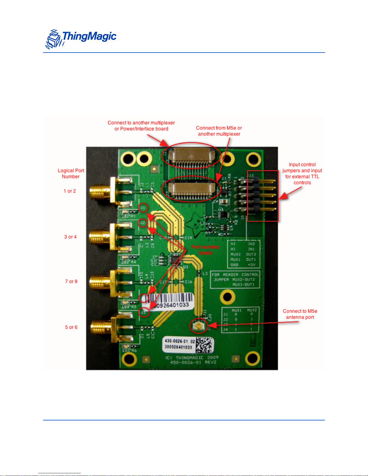
4 Port Multiplexer Board
The multiplexer board contains the following important I/O and control components:
Multiplexer Components
4 Port Multiplexer Board
The physical antenna port in use, labeled J1 through J4 on the board, is controlled by the
MUX1 and MUX2 input lines on the input terminal connector. The control map is as
follows:
4 Accessory Board Configuration
Page 6

4 Port Multiplexer Board
Antenna Port Control Lines
MUX1 MUX2
00
J1
01
J2
10
J3
11
J4
Note
Interpreting the control lines as binary “numbers” gives an incorrect order
relative to the physical order of the ports. A key printed on the board serves
as a reminder that, from left to right when looking down at the board, the port
order is J1 – J2 – J4 – J3.
These lines can be controlled directly by an external controller/motherboard providing
TTL signals or by using signals from the M5e.
External MUX Control (Block 23)
When controlling the Multiplexer using external TTL signals the terminal pins on the board
serve as input signals as defined in Antenna Port Control Lines
the M5e software has no knowledge of which multiplexed line is in use. All antenna ports
on a Multiplexer will look like Antenna 1 or 2 (depending on which M5e port is used) and
the associated Antenna ID metadata will be the same for all four ports. It is the users
responsibility to manage coordination between the MUX control line settings and the M5e
RF operations and tag response data.
For this configuration no jumpers should be present on terminal block 23.
table. In this configuration
Accessory Board Configuration 5
Page 7
4 Port Multiplexer Board
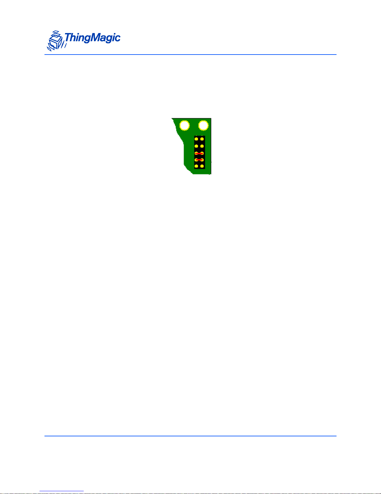
M5e Control (Block 23)
The Multiplexer can be controlled using the M5e GPOutput lines by connecting the ribbon
cable between the M5e and the Multiplexer board and adding jumpers on the terminal
pins, connecting MUX2 with OUT2 and MUX1 with OUT1.
This method allows the M5e to use its built-in support for (up to 8) multiplexed antennas.
This enables automatic control of GPO to MUX signals to switch ports based on the M5e
logical antenna setting and association of tag read information with the corresponding
antenna ID meta data.
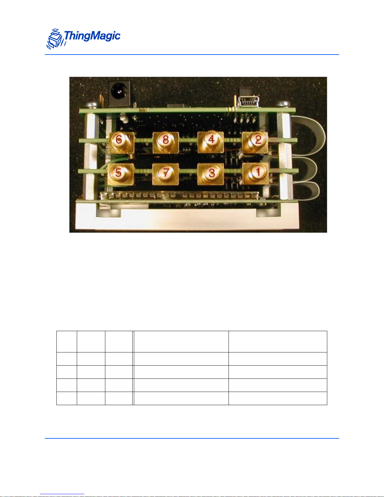
When using the M5e built-in multiplexer support the ports are also identified by predefined logical port numbers - this requires M5e firmware version 1.3.0 or later. In a
stacked configuration, multiplexers are installed upside-down relative to the M5e board.
Assuming that the multiplexer closest to the M5e is connected to M5e port 1 and the one
farthest is connected to M5e port 2, the logical port numbers would be as shown here:
6 Accessory Board Configuration
Page 8
Logical Port Configuration
4 Port Multiplexer Board
The reason for numbering the logical ports in this way was so that “logical port 1” would
stay associated with physical port 1 on the module whether there was a multiplexer
connected to it or not and, similarly, “logical port 2” would stay associated with physical
port 2 whether there was a multiplexer connected to it or not. If the application calls for a
mixture of manual control of the multiplexer (via physical port selection and GPIO Output
line manipulation) and automatic control (by configuring a search list of logical antennas),
the benefits of this numbering system will be more clear.
The resulting full control map with physical and logical port numbering is:
Physical to Logical Port Map
MUX1 MUX2
001 2
J1
013 4
J2
107 8
J3
115 6
J4
Logical Port when
connected to port 1 of M5e
Logical Port when
connected to port 2 of M5e
Accessory Board Configuration 7
Page 9

4 Port Multiplexer Board
Terminal Block 23 Pins
The following Block 23 Pin Function Summary table contains a detailed list of the terminal
block 23 pins and their function based on the overall board configuration, whether the
multiplexer to M5e ribbon cable is connected and whether the jumper blocks are
connecting the multiplexer to a controller motherboard. A printed key on the multiplexer
board below the terminal pins also indicates which jumper pins are connected to which
internal function.
Block 23 Pin Function Summary
If multiplexer is
Termin a l
pin
What it is
connected to
If multiplexer is connected
to motherboard through the
ribbon cable connector
connected to
motherboard through
Molex connector to
jumper block
IN1 GPIO Input #1
(Input to module)
IN2 GPIO Input #2
(Input to module)
MUX1 Mux switch control Jumper to OUT1 (GPIO Output
Ignore Bring in GPIO Input signal
Ignore Bring in GPIO Input signal
#1) if multiplexer is to be controlled by module.
to module through this
pin. If no ribbon cable connection, it is naturally
pulled low. Jumper to “HI”
if the application requires
this input to be driven high
at all times.
to module through this
pin. If no ribbon cable connection, it is naturally
pulled low. Jumper to “HI”
if the application requires
this input to be driven high
at all times.
Use this pin to bring in
external control from
motherboard if multiplexer is not controlled
through ribbon cable.
8 Accessory Board Configuration
Page 10

4 Port Multiplexer Board
MUX1 Mux switch control Jumper to OUT1 (GPIO Output
#1) if multiplexer is to be controlled by module.
+5 +5V source to
multiplexer
Gnd Ground to multi-
plexer
Ignore Use this pin to bring in
Ignore Use this pin to bring
Use this pin to bring in
external control from
motherboard if multiplexer is not controlled
through ribbon cable.
+5V from motherboard if
multiplexer is not connected to power source
through ribbon cable.
ground to multiplexer from
motherboard if multiplexer is not connected to
power source through ribbon cable.
Antenna Detection
When using the multiplexer in the M5e Control (Block 23) configuration the M5e
functionality for manually (Get Antenna Configuration - 61h command) and automatically
(Set Reader Configuration - 9Bh, option 0x04 - Check Antenna Connection) detecting
connected antennas can be used.
This functionality requires the M5e module to be running firmware v1.3.0 or later.
Note
Reliable antenna detection requires that an attached antenna pass at least a
small amount of DC current. Many antennas do not pass DC current. Due to
such antennas an indication that a port is connected/terminated is always
accurate, but an indication that a port is not connected/terminated may not
be accurate.
Accessory Board Configuration 9
Page 11

Power/Interface Board
The Power/Interface board has one set of jumper blocks and three sets of terminal blocks
as shown in the Power/Interface Components
Power/Interface Components
Power/Interface Board
image below.
10 Accessory Board Configuration
Page 12

Power/Interface Board
USB Interface
The power/interface board uses the FTDI FT232R IC for its USB interface. Drivers and
installation guides for installing the necessary device drivers along with source code to
build the drivers for many other operating systems can be found at:
http://www.ftdichip.com/Drivers/VCP.htm
To use the USB connector, configure the USB jumpers as shown in the diagram next to
the jumper block (the CONV configuration, the INT setting is not supported) and in the
Power/Interface Components
image above.
Alternate Command Interface (Block J3)
Terminal block J3 is used for two purposes:
Provide alternative transmit and receive signal interface (compatible with Molex-style
connector) if TTL rather than USB is used for input and enable signals.
Provide an alternate means of enabling the module if USB is not used (and therefore
the 5V USB input signal is not available. Jump GND pin to Enable pin to turn on
module permanently:
Accessory Board Configuration 11
Page 13
Power/Interface Board
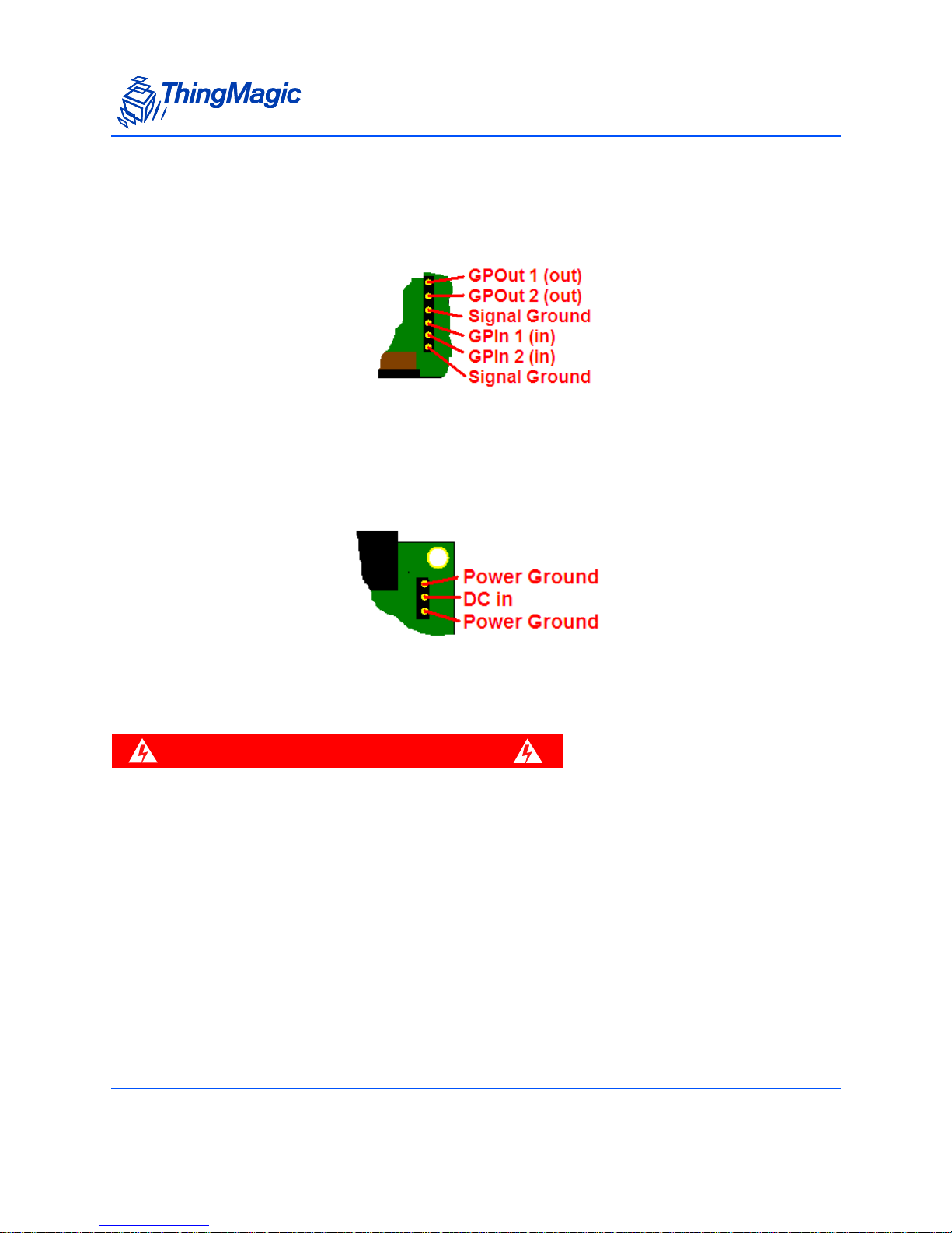
Alternate GPIO Interface (Block J7)
Terminal block J7 provides a TTL interface for reading and controlling the GPIO lines of
the module (via Molex-style connectors).
Alternate Power Input (Block J1)
Terminal block J1 is used to bring DC power (7 to 24 V) into the module through a Molexstyle connector as an alternative to using the round 2.1mm jack.
EU Regulatory Warning
WARNING!
The Power / Interface board does not pass EU regulations for
unintentional radiation without additional shielding. It does pass FCC
regulations.
12 Accessory Board Configuration
Page 14

Accessory Parts Kit
The following parts are included in the optional parts kit which provides all the necessary
parts to build up an 8-port multiplexer using two 4 Port Multiplexer Board
Board, a heat sink and an M5e. The label before each part refers to its location in the full
assembly as show in theAccessory Parts Kit Diagram
A, B, C: M/F Standoffs, M3, 10 mm
Notes: Stand-offs for first multiplexer, second multiplexer and power/interface board.
Part Number: Digi-Key 24337K-ND
D: MMCX to U.FL (IPX) cable, RTANG Plug
Notes: RF Cable for multiplexer
Accessory Parts Kit
, a Power/Interface
.
Part Number: Lighthorse Technologies CB1.32-IPX-MCLMGT-1.5”-NH
E: M3 pan-head screws, 6 mm (DIN 7985)
Notes: Screw for top board
Part Number: Digi-Key H742
Part Number: McMaster-Carr 92005A116
F: M3 Flat Lockwashers (DIN 7980)
Notes: Washer for top board
Part Number: McMa ster -Car r 9 1111A118 ; 100 for $1.43
G: 2” Ribbon Cable, 12 pos, 1mm pitch
Notes: Only short cables needed if power/interface board mounted upside-down as
are multiplexers.
Part Number: Digi-Key WM10003-ND (Molex 21039-0269)
Accessory Board Configuration 13
Page 15

Accessory Parts Kit Diagram
Accessory Parts Kit
14 Accessory Board Configuration
Page 16

Connecting the Accessory Boards
Connecting the Accessory Boards
The multiplexer is designed so that it can be mounted above or to the side of the M5e
module. Either way, it is best to connect the modules to each other side by side, and then,
if desired, rotate one module above the other. Refer to the section that explains how the
boards are installed for detailed information.
The multiplexer is connected to the module as shown below. (The contacts on the ribbon
cable are facing down). This same connection method can be used for the power/
interface board except in the side-by-side configuration it will face component side down
As noted previously, if the multiplexer is stacked on top of the module, it will be upside
down with respect to the module.
A full stack, of an M5e, 2 multiplexers, a power board and heat sink, will stack as shown
below in the Logical Port Configuration
Accessory Board Configuration 15
image and the Accessory Parts Kit Diagram.
Page 17

Connecting the Accessory Boards
16 Accessory Board Configuration
Page 18

Appendix A: Accessory Specifications
Appendix A: Accessory Specifications 17
Page 19

4 Port Multiplexer
Compatibility
M5e, M5e-EU or M5e-Compact Modules
RF Ports
One 50 Ohm U.FL Common port; 4 SMA Switched Ports
Control Ports
Two module TTL GPIO lines on two “Pass Through” 12-Pin ZIF Ribbon cable connectors
or TTL on terminal block
Insertion Loss
4 Port Multiplexer
1 dB max
Frequency Range
840 – 960 MHz with DC pass-through for antenna detection
Power
3 to 5.5 V, 1 mA max
Operating Temp.
-40o to +85oC
Dimensions
82 mm L x 64 mm W (including connector overhang) x 8.5 mm H
18 Appendix A: Accessory Specifications
Page 20

Power Interface
Interfaces
Power Input: 2.1mm DC input jack; Interface Input: USB mini-B jack or TTL on terminal
block; Interface and Power Output: 12-pin ZIF ribbon cable connector
Output Power
5 V +/- 0.25 V at 2 A max
Input Power
8 to 24 VDC (12.5 W max, max current depends on voltage) (USB 5V is used only to
detect port is active, not to power module)
Operating Temperature
Power Interface
-40o to +65oC
Dimensions
82 mm L x 56 mm W (including connector overhang) x 15 mm H
USB Interface
Up to 921.6 kbps (limit of M5e module)
Appendix A: Accessory Specifications 19
Page 21

Heatsink
Compatibility
Supports M5e and M5e-EU Modules
Dimensions
82 mm L x 54 mm W x 10 mm H
Mounting
M5e module is mounted to the heatsink using off-the-shelf M3 hardware (not included).
Heatsink can be mounted to chassis via M3 screws or M3 threaded mounting posts & nut.
Thermal pads are included.
Heatsink
20 Appendix A: Accessory Specifications
 Loading...