

Page 1

Mer cury5e and M5e-Compact Developer’s Guide
For: Mercury5e and M5e-Compact (v1.7.1 and later)
USB Reader and Vega Reader
875-0016-07 RevA
Page 2

Government Limited Rights Notice: All documentation and manuals
were developed at private expense and no part of it was developed using
Government funds.
The U.S. Government’s rights to use, modify, reproduce, release, perform,
display, or disclose the technical data contained herein are restricted by
paragraph (b)(3) of the Rights in Technical Data — Noncommercial Items
clause (DFARS 252.227-7013(b)(3)), as amended from time-to-time. Any
reproduction of technical data or portions thereof marked with this legend
must also reproduce the markings. Any person, other than the U.S.
Government, who has been provided access to such data must promptly
notify ThingMagic, Inc.
ThingMagic, Mercury, Reads Any Tag, and the ThingMagic logo are
trademarks or registered trademarks of ThingMagic, Inc.
Other product names mentioned herein may be trademarks or registered
trademarks of ThingMagic, Inc. or other companies.
©2012 ThingMagic – a division of Trimble Navigation Limited. ThingMagic
and The Engine in RFID are registered trademarks of Trimble Navigation
Limited. Other marks may be protected by their respective owners. All
Rights Reserved.
ThingMagic
A Division of Trimble
One Cambridge Center, 11th floor
Cambridge, MA 02142.
866-833-4069
07 Revision A
January, 2012
Page 3

Revision Table
Date Version Description
2/2008 Rev1 Separated out M4e content and Reader Assistant into standalone
documents. Created new M5e Family DevGuide
2/2008 Rev1 Updated TX Power section to correct TX Write power note.
2/2008 Rev1 Fixed Send CW Signal content with correct value for PRBS signal.
3/2008 Rev1 Added input voltage details to M5e/C Hardware comparison table.
3/2008 Rev1 Added FCC and IC Regulatory Statements
3/2008 Rev1 Updated timestamp field in Tag Read Meta Data description to indi-
cate its ticks from read command invocation.
3/2008 Rev1 Added details on new functionality for release 1.0.37:
• M5e EU info (Hardware Support)
• PRC (China) region support (get/set Current Region)
• Support for user control of Gen2 Q value (Get/Set Protocol
Parameter)
• LBT on/off and LBT Threshold setting in supported regions
(Get/Set Current Region) and LBT default settings in
Regulatory Support section.
• Custom NXP Silicon Commands (Tag Specific)
• Get Reader Statistics
• Get tag read metadata with Read Tag Single
• Get tag read metadata with Read Tag Data
• Read Tag Multiple with Tag Singulation
• Read Tag Multiple with embedded commands
• Updates to Tag Select functionality
4/2008 Rev1 Added Gen2 Memory Map and algorithm information to Tag Singu-
lation section.
4/2008 Rev2
Added information on Transmit mode power consumption to
Trans -
mit Modes
4/2008 Rev2 Corrected NXP command:
• names: changed ‘Quiet’ to ‘ReadProtect’
• EAS Alarm and Calibrate syntax
3
Page 4

Date Version Description
6/2008 Rev3 • Fixed Arbser help info to include -l5a for loading M5e firmware
• Fixed Get Tag Buffer Response Fields to show Read Count as
conditional
9/2008 02 RevA • Added info on EU2 usage and caution
• Update Get/Set Reader Configuration commands to reflect the
new key/value pair format
• Fixed the CRC calc sample code
• Fixed PRC region frequency range
11/2008 02 RevA • added info about why use Write Tag EPC over Write Tag Data
4/2009 03 RevA • Added 1.1.1 features
6/2009 04 Rev1 • fixed response fields - missing metadata field - in Get Tag
8/2009 04 Rev1 • Fixed Read Tag Data meta data fields
12/2010 05 Rev1 • Added detail to Tag Singulation/Select section
3/2011 06 Rev1 Updates for firmware v1.5.1
1/2012 07 RevA Updates for firmware 1.5.2
Buffer
• KR2 region support info
• misc doc bug fixes
• Updated RS232 electical specs
• Added MercuryAPI info
• updated copyright and FCC info with new company info
• added note to Lock Tag
• New Custom commands support
• more data returned for embedded tag read data operations.
• Set Gen2 Write Response Time (under 0x9B)
• IDS SL900A
Gen2 Tag Specific (2Dh) support
4
Page 5

Communication Regulation Information
Communication Regulation Information
EMC FCC 47 CFR, Part 15
Industrie Canada RSS-210
Federal Communication Commission Interference Statement
This equipment has been tested and found to comply with the limits for a Class B
digital device, pursuant to Part 15 of the FCC Rules. These limits are designed to
provide reasonable protection against harmful interference in a residential installation.
This equipment generates uses and can radiate radio frequency energy and, if not
installed and used in accordance with the instructions, may cause harmful interference to
radio communications. However, there is no guarantee that interference will not occur in a
particular installation. If this equipment does cause harmful interference to radio or
television reception, which can be determined by turning the equipment off and on, the
user is encouraged to try to correct the interference by one of the following measures:
Reorient or relocate the receiving antenna.
Increase the separation between the equipment and receiver.
Connect the equipment into an outlet on a circuit different from that to which the
receiver is connected.
Consult the dealer or an experienced radio/TV technician for help.
This device complies with Part 15 of the FCC Rules. Operation is subject to the following
two conditions: (1) This device may not cause harmful interference, and (2) this device
must accept any interference received, including interference that may cause undesired
operation.
FCC Caution: Any changes or modifications not expressly approved by the party
responsible for compliance could void the user's authority to operate this equipment.
This transmitter module is authorized to be used in other devices only by OEM
integrators under the following conditions:
1. The antenna(s) must be installed such that a minimum separation distance of 25cm is
maintained between the radiator (antenna) & user’s/nearby people’s body at all
times.
2. The transmitter module must not be co-located with any other antenna or transmitter.
As long as the two conditions above are met, further transmitter testing will not be
required. However, the OEM integrator is still responsible for testing their end-product for
5
Page 6

Communication Regulation Information
any additional compliance requirements required with this module installed (for example,
digital device emissions, PC peripheral requirements, etc.).
Note
In the event that these conditions can not be met (for certain configurations
or co-location with another transmitter), then the FCC authorization is no
longer considered valid and the FCC ID can not be used on the final product.
In these circumstances, the OEM integrator will be responsible for reevaluating the end product (including the transmitter) and obtaining a
separate FCC authorization.
The OEM integrator has to be aware not to provide information to the end user regarding
how to install or remove this RF module in the user manual of the end product.
User Manual Requirement
The user manual for the end product must include the following information in a
prominent location;
“To comply with FCC’s RF radiation exposure requirements, the antenna(s) used for this
transmitter must be installed such that a minimum separation distance of 25cm is
maintained between the radiat or (antenna) & user’s/nearby people’s body at all times and
must not be co-located or operating in conjunction with any other antenna or transmitter.”
AND
“The transmitting portion of this devi ce carries with it the following two warnings:
“This device complies with Part 15....”
AND
“Any changes or modifications to the transmitting module not expressly approv ed by
ThingMagic Inc. could void the user’s authority to operate thi s equipment” “
End Product Labeling
The final end product must be labeled in a visible area with the following:
“Contains Transmitter Module FCC ID: QV5MERCURY5E”
6
Page 7

Communication Regulation Information
or
“Contains FCC ID: QV5MERCURY5E.”
(Replace QV5MERCURY5E, for the Mercury5e, with QV5MERCURY5EC for the M5eCompact).
Industry Canada
Operation is subject to the following two conditions: (1) this device may not cause
interference, and (2) this device must accept any interference, including interference that
may cause undesired operation of the device.
To reduce potential radio interference to other users, the antenna type and its gain should
be so chosen that the equivalent isotropically radiated power (e.i.r.p.) is not more than
that permitted for successful communication.
This device has been designed to operate with the antennas listed in Authorized Antennas
Antennas not included in this list are strictly prohibited for use with this device.
To comply with IC RF exposure limits for general population/uncontrolled exposure, the
antenna(s) used for this transmitter must be installed to provide a separation distance of
at least 25 cm from all persons and must not be collocated or operating in conjunction
with any other antenna or transmitter.
End Product Labeling
The final end product must be labeled in a visible area with the following:
“Contains ThingMagic Inc. M5e-Compact (or appropriate model number you’re filing with
IC) transmitting module FCC ID: QV5MERCURY5EC (IC: 5407A-MERCURY5EC)”
.
7
Page 8

Communication Regulation Information
8
Page 9

Contents
Communication Regulation Information . . . . . . . . . . . . . . . . . . . . . . . . . . . . . . . . . . . . . . . . . . . . . . . . . . . . . . . 5
Federal Communication Commission Interference Statement . . . . . . . . . . . . . . . . . . . . . . . . . . . . . . . . . . 5
Industry Canada . . . . . . . . . . . . . . . . . . . . . . . . . . . . . . . . . . . . . . . . . . . . . . . . . . . . . . . . . . . . . . . . . . . . . . . 7
Introduction . . . . . . . . . . . . . . . . . . . . . . . . . . . . . . . . . . . . . . . . . . . . . . . . . . . . . . . . . . . . . . . .21
Product Line Overview . . . . . . . . . . . . . . . . . . . . . . . . . . . . . . . . . . . . . . . . . . . . . . . . . . . . . . . . . . . . . . . . . . . . . . 22
Product Specifications . . . . . . . . . . . . . . . . . . . . . . . . . . . . . . . . . . . . . . . . . . . . . . . . . . . . . . . . . . . . . . . . . 22
Hardware Overview . . . . . . . . . . . . . . . . . . . . . . . . . . . . . . . . . . . . . . . . . . . . . . . . . . . . . . . . . . . . . . . . . . . . . . . . .23
M5e and M5e-Compact Hardware . . . . . . . . . . . . . . . . . . . . . . . . . . . . . . . . . . . . . . . . . . . . . . . . . . . . . . . 23
Microcontroller. . . . . . . . . . . . . . . . . . . . . . . . . . . . . . . . . . . . . . . . . . . . . . . . . . . . . . . . . . . . . . . . . . . . . 23
RFID ASIC . . . . . . . . . . . . . . . . . . . . . . . . . . . . . . . . . . . . . . . . . . . . . . . . . . . . . . . . . . . . . . . . . . . . . . . . 24
Connectors . . . . . . . . . . . . . . . . . . . . . . . . . . . . . . . . . . . . . . . . . . . . . . . . . . . . . . . . . . . . . . . . . . . . . . . 24
Hardware Revisions . . . . . . . . . . . . . . . . . . . . . . . . . . . . . . . . . . . . . . . . . . . . . . . . . . . . . . . . . . . . . . . . . . . 25
M5e/M5e-Compact Digital Connectors . . . . . . . . . . . . . . . . . . . . . . . . . . . . . . . . . . . . . . . . . . . . . . . . . . . 25
M5e and M5e-Compact Connector . . . . . . . . . . . . . . . . . . . . . . . . . . . . . . . . . . . . . . . . . . . . . . . . . . . 25
SW Overview . . . . . . . . . . . . . . . . . . . . . . . . . . . . . . . . . . . . . . . . . . . . . . . . . . . . . . . . . . . . . . . . . . . . . . . . . . . . . . .26
Boot Loader. . . . . . . . . . . . . . . . . . . . . . . . . . . . . . . . . . . . . . . . . . . . . . . . . . . . . . . . . . . . . . . . . . . . . . . . . . 27
Application Firmware . . . . . . . . . . . . . . . . . . . . . . . . . . . . . . . . . . . . . . . . . . . . . . . . . . . . . . . . . . . . . . . . . . 27
Verifying Application FW Image CRC . . . . . . . . . . . . . . . . . . . . . . . . . . . . . . . . . . . . . . . . . . . . . . . . . . 27
About the Reader Assistant . . . . . . . . . . . . . . . . . . . . . . . . . . . . . . . . . . . . . . . . . . . . . . . . . . . . . . . . . . 28
Application Development . . . . . . . . . . . . . . . . . . . . . . . . . . . . . . . . . . . . . . . . . . . . . . . . . . . . . . . . . . . . 28
Functionality of the Embedded Modules . . . . . . . . . . . . . . . . . . . . . . . . . . . . . . . . . . . . . .29
Regional Support . . . . . . . . . . . . . . . . . . . . . . . . . . . . . . . . . . . . . . . . . . . . . . . . . . . . . . . . . . . . . . . . . . . . . . . . . . . 29
Frequency Setting . . . . . . . . . . . . . . . . . . . . . . . . . . . . . . . . . . . . . . . . . . . . . . . . . . . . . . . . . . . . . . . . . . . . . . . . . .32
Frequency Units . . . . . . . . . . . . . . . . . . . . . . . . . . . . . . . . . . . . . . . . . . . . . . . . . . . . . . . . . . . . . . . . . . . . . . 32
Frequency Hop Table . . . . . . . . . . . . . . . . . . . . . . . . . . . . . . . . . . . . . . . . . . . . . . . . . . . . . . . . . . . . . . . . . . 33
EU3 Region . . . . . . . . . . . . . . . . . . . . . . . . . . . . . . . . . . . . . . . . . . . . . . . . . . . . . . . . . . . . . . . . . . . . . . . 34
PRC Region . . . . . . . . . . . . . . . . . . . . . . . . . . . . . . . . . . . . . . . . . . . . . . . . . . . . . . . . . . . . . . . . . . . . . . . 34
KR2 Region . . . . . . . . . . . . . . . . . . . . . . . . . . . . . . . . . . . . . . . . . . . . . . . . . . . . . . . . . . . . . . . . . . . . . . . 34
RF Power Setting . . . . . . . . . . . . . . . . . . . . . . . . . . . . . . . . . . . . . . . . . . . . . . . . . . . . . . . . . . . . . . . . . . . . . . . . . . . 35
Mercury Embedded Modules Developer’s Guide 9
Page 10

Power Units . . . . . . . . . . . . . . . . . . . . . . . . . . . . . . . . . . . . . . . . . . . . . . . . . . . . . . . . . . . . . . . . . . . . . . . . . . 35
Power Calibration . . . . . . . . . . . . . . . . . . . . . . . . . . . . . . . . . . . . . . . . . . . . . . . . . . . . . . . . . . . . . . . . . . . . . 35
TX Read Power . . . . . . . . . . . . . . . . . . . . . . . . . . . . . . . . . . . . . . . . . . . . . . . . . . . . . . . . . . . . . . . . . . . . . . . 35
TX Write Power. . . . . . . . . . . . . . . . . . . . . . . . . . . . . . . . . . . . . . . . . . . . . . . . . . . . . . . . . . . . . . . . . . . . . . . 36
Antenna Ports . . . . . . . . . . . . . . . . . . . . . . . . . . . . . . . . . . . . . . . . . . . . . . . . . . . . . . . . . . . . . . . . . . . . . . . . . . . . . .36
Monostatic Mode . . . . . . . . . . . . . . . . . . . . . . . . . . . . . . . . . . . . . . . . . . . . . . . . . . . . . . . . . . . . . . . . . . . . . 37
Bistatic Mode . . . . . . . . . . . . . . . . . . . . . . . . . . . . . . . . . . . . . . . . . . . . . . . . . . . . . . . . . . . . . . . . . . . . . . . . 37
Using a Multiplexer . . . . . . . . . . . . . . . . . . . . . . . . . . . . . . . . . . . . . . . . . . . . . . . . . . . . . . . . . . . . . . . . . . . . 37
Power Management. . . . . . . . . . . . . . . . . . . . . . . . . . . . . . . . . . . . . . . . . . . . . . . . . . . . . . . . . . . . . . . . . . . . . . . . . 40
Power Modes . . . . . . . . . . . . . . . . . . . . . . . . . . . . . . . . . . . . . . . . . . . . . . . . . . . . . . . . . . . . . . . . . . . . . . . . 40
Transmit Modes. . . . . . . . . . . . . . . . . . . . . . . . . . . . . . . . . . . . . . . . . . . . . . . . . . . . . . . . . . . . . . . . . . . . . . . 40
High Performance Mode. . . . . . . . . . . . . . . . . . . . . . . . . . . . . . . . . . . . . . . . . . . . . . . . . . . . . . . . . . . . . 40
Low Power Mode . . . . . . . . . . . . . . . . . . . . . . . . . . . . . . . . . . . . . . . . . . . . . . . . . . . . . . . . . . . . . . . . . . 41
Tag Buffer. . . . . . . . . . . . . . . . . . . . . . . . . . . . . . . . . . . . . . . . . . . . . . . . . . . . . . . . . . . . . . . . . . . . . . . . . . . . . . . . . .42
Tag Operations . . . . . . . . . . . . . . . . . . . . . . . . . . . . . . . . . . . . . . . . . . . . . . . . . . . . . . . . . . . . . . . . . . . . . . . . . . . . .45
Custom Tag Commands . . . . . . . . . . . . . . . . . . . . . . . . . . . . . . . . . . . . . . . . . . . . . . . . . . . . . . . . . . . . . . . 45
Flash Memory . . . . . . . . . . . . . . . . . . . . . . . . . . . . . . . . . . . . . . . . . . . . . . . . . . . . . . . . . . . . . . . . . . . . . . . . . . . . . .45
Accessing the Flash . . . . . . . . . . . . . . . . . . . . . . . . . . . . . . . . . . . . . . . . . . . . . . . . . . . . . . . . . . . . . . . . . . . 46
Upgrading Application FW. . . . . . . . . . . . . . . . . . . . . . . . . . . . . . . . . . . . . . . . . . . . . . . . . . . . . . . . . . . . . . 46
Direct Flash Addressing . . . . . . . . . . . . . . . . . . . . . . . . . . . . . . . . . . . . . . . . . . . . . . . . . . . . . . . . . . . . . . . . 46
M4e Direct Flash Addressing. . . . . . . . . . . . . . . . . . . . . . . . . . . . . . . . . . . . . . . . . . . . . . . . . . . . . . . . . 47
M5e Flash Addressing . . . . . . . . . . . . . . . . . . . . . . . . . . . . . . . . . . . . . . . . . . . . . . . . . . . . . . . . . . . . . . 48
Serial Port. . . . . . . . . . . . . . . . . . . . . . . . . . . . . . . . . . . . . . . . . . . . . . . . . . . . . . . . . . . . . . . . . . . . . . . . . . . . . . . . . .49
General Purpose Inputs/Outputs (GPIO) . . . . . . . . . . . . . . . . . . . . . . . . . . . . . . . . . . . . . . . . . . . . . . . . . . . . .49
M5e and M5e-Compact GPIOs . . . . . . . . . . . . . . . . . . . . . . . . . . . . . . . . . . . . . . . . . . . . . . . . . . . . . . . . . 50
Default Settings . . . . . . . . . . . . . . . . . . . . . . . . . . . . . . . . . . . . . . . . . . . . . . . . . . . . . . . . . . . . . . . . . . . . . . . . . . . .51
Overview of the Communication Protocol . . . . . . . . . . . . . . . . . . . . . . . . . . . . . . . . . . . . .53
Host-to-Reader Communication . . . . . . . . . . . . . . . . . . . . . . . . . . . . . . . . . . . . . . . . . . . . . . . . . . . . . . . . . . . . .53
Reader-to-Host Communication . . . . . . . . . . . . . . . . . . . . . . . . . . . . . . . . . . . . . . . . . . . . . . . . . . . . . . . . . . . . .55
CCITT CRC-16 Calculation . . . . . . . . . . . . . . . . . . . . . . . . . . . . . . . . . . . . . . . . . . . . . . . . . . . . . . . . . . . . . 56
Format for Microprocessor Reply to Host . . . . . . . . . . . . . . . . . . . . . . . . . . . . . . . . . . . . . . . . . . . . . . . . . . . . .58
Microprocessor ACK Message . . . . . . . . . . . . . . . . . . . . . . . . . . . . . . . . . . . . . . . . . . . . . . . . . . . . . . . . . . 58
Microprocessor Fault Reply Message. . . . . . . . . . . . . . . . . . . . . . . . . . . . . . . . . . . . . . . . . . . . . . . . . . . . . 59
Microprocessor Data Reply Message . . . . . . . . . . . . . . . . . . . . . . . . . . . . . . . . . . . . . . . . . . . . . . . . . . . . . 59
Command Set . . . . . . . . . . . . . . . . . . . . . . . . . . . . . . . . . . . . . . . . . . . . . . . . . . . . . . . . . . . . . .61
Format for Microprocessor Reply to Host . . . . . . . . . . . . . . . . . . . . . . . . . . . . . . . . . . . . . . . . . . . . . . . . . . . . .62
10 Mercury Embedded Modules Developer’s Guide
Page 11

Microprocessor ACK Message . . . . . . . . . . . . . . . . . . . . . . . . . . . . . . . . . . . . . . . . . . . . . . . . . . . . . . . . . . 62
Microprocessor Fault Reply Message. . . . . . . . . . . . . . . . . . . . . . . . . . . . . . . . . . . . . . . . . . . . . . . . . . . . . 63
Microprocessor Data Reply Message . . . . . . . . . . . . . . . . . . . . . . . . . . . . . . . . . . . . . . . . . . . . . . . . . . . . . 63
Boot Loader Commands . . . . . . . . . . . . . . . . . . . . . . . . . . . . . . . . . . . . . . . . . . . . . . . . . . . . . . . . . . . . . . . . . . . .64
Read Flash (02h). . . . . . . . . . . . . . . . . . . . . . . . . . . . . . . . . . . . . . . . . . . . . . . . . . . . . . . . . . . . . . . . . . . . . . 66
M5e/M5e-Compact Flash Read Example . . . . . . . . . . . . . . . . . . . . . . . . . . . . . . . . . . . . . . . . . . . . . . . 66
Error Status Codes . . . . . . . . . . . . . . . . . . . . . . . . . . . . . . . . . . . . . . . . . . . . . . . . . . . . . . . . . . . . . . . . . 66
Get Boot Loader/Firmware Version (03h) . . . . . . . . . . . . . . . . . . . . . . . . . . . . . . . . . . . . . . . . . . . . . . . . . 67
M5e-Compact and M5e Command Responses. . . . . . . . . . . . . . . . . . . . . . . . . . . . . . . . . . . . . . . . . . 67
Returned Hardware Version Table. . . . . . . . . . . . . . . . . . . . . . . . . . . . . . . . . . . . . . . . . . . . . . . . . . . . . 68
Error Status Codes . . . . . . . . . . . . . . . . . . . . . . . . . . . . . . . . . . . . . . . . . . . . . . . . . . . . . . . . . . . . . . . . . 68
Boot Firmware (04h). . . . . . . . . . . . . . . . . . . . . . . . . . . . . . . . . . . . . . . . . . . . . . . . . . . . . . . . . . . . . . . . . . . 69
Error Status Codes . . . . . . . . . . . . . . . . . . . . . . . . . . . . . . . . . . . . . . . . . . . . . . . . . . . . . . . . . . . . . . . . . 69
Set Baud Rate (06h) . . . . . . . . . . . . . . . . . . . . . . . . . . . . . . . . . . . . . . . . . . . . . . . . . . . . . . . . . . . . . . . . . . 69
Error Status Codes . . . . . . . . . . . . . . . . . . . . . . . . . . . . . . . . . . . . . . . . . . . . . . . . . . . . . . . . . . . . . . . . . 70
Verify Image CRC (08h) . . . . . . . . . . . . . . . . . . . . . . . . . . . . . . . . . . . . . . . . . . . . . . . . . . . . . . . . . . . . . . . . 70
Error Status Codes . . . . . . . . . . . . . . . . . . . . . . . . . . . . . . . . . . . . . . . . . . . . . . . . . . . . . . . . . . . . . . . . . 71
Start Bootloader (09h) . . . . . . . . . . . . . . . . . . . . . . . . . . . . . . . . . . . . . . . . . . . . . . . . . . . . . . . . . . . . . . . . . 71
Error Status Codes . . . . . . . . . . . . . . . . . . . . . . . . . . . . . . . . . . . . . . . . . . . . . . . . . . . . . . . . . . . . . . . . . 71
Get Current Program (0Ch). . . . . . . . . . . . . . . . . . . . . . . . . . . . . . . . . . . . . . . . . . . . . . . . . . . . . . . . . . . . . 72
Error Status Codes . . . . . . . . . . . . . . . . . . . . . . . . . . . . . . . . . . . . . . . . . . . . . . . . . . . . . . . . . . . . . . . . . 72
Write Flash Sector (0Dh) . . . . . . . . . . . . . . . . . . . . . . . . . . . . . . . . . . . . . . . . . . . . . . . . . . . . . . . . . . . . . . . 72
Error Status Codes . . . . . . . . . . . . . . . . . . . . . . . . . . . . . . . . . . . . . . . . . . . . . . . . . . . . . . . . . . . . . . . . . 73
Get Sector Size (0Eh) . . . . . . . . . . . . . . . . . . . . . . . . . . . . . . . . . . . . . . . . . . . . . . . . . . . . . . . . . . . . . . . . . 73
Error Status Codes . . . . . . . . . . . . . . . . . . . . . . . . . . . . . . . . . . . . . . . . . . . . . . . . . . . . . . . . . . . . . . . . . 73
Modify Flash Sector (0Fh) . . . . . . . . . . . . . . . . . . . . . . . . . . . . . . . . . . . . . . . . . . . . . . . . . . . . . . . . . . . . . . 73
Error Status Codes . . . . . . . . . . . . . . . . . . . . . . . . . . . . . . . . . . . . . . . . . . . . . . . . . . . . . . . . . . . . . . . . . 74
Application Tag Commands . . . . . . . . . . . . . . . . . . . . . . . . . . . . . . . . . . . . . . . . . . . . . . . . . . . . . . . . . . . . . . . . . 75
Tag Singulation/Select Functionality . . . . . . . . . . . . . . . . . . . . . . . . . . . . . . . . . . . . . . . . . . . . . . . . . . . . . . 75
Select Algorithm and Parameters . . . . . . . . . . . . . . . . . . . . . . . . . . . . . . . . . . . . . . . . . . . . . . . . . . . . . 75
Select Process . . . . . . . . . . . . . . . . . . . . . . . . . . . . . . . . . . . . . . . . . . . . . . . . . . . . . . . . . . . . . . . . . . . . 77
Flag Persistence Rules . . . . . . . . . . . . . . . . . . . . . . . . . . . . . . . . . . . . . . . . . . . . . . . . . . . . . . . . . . . . . . 78
Operations supporting Tag Singulation/Select . . . . . . . . . . . . . . . . . . . . . . . . . . . . . . . . . . . . . . . . . . 79
Gen2 Memory Map . . . . . . . . . . . . . . . . . . . . . . . . . . . . . . . . . . . . . . . . . . . . . . . . . . . . . . . . . . . . . . . . . 82
Read Tag Single (21h) . . . . . . . . . . . . . . . . . . . . . . . . . . . . . . . . . . . . . . . . . . . . . . . . . . . . . . . . . . . . . . . . . 83
Get Tag EPC . . . . . . . . . . . . . . . . . . . . . . . . . . . . . . . . . . . . . . . . . . . . . . . . . . . . . . . . . . . . . . . . . . . . . . 83
Get Tag EPC and Meta Data . . . . . . . . . . . . . . . . . . . . . . . . . . . . . . . . . . . . . . . . . . . . . . . . . . . . . . . . . 84
Error Status Codes . . . . . . . . . . . . . . . . . . . . . . . . . . . . . . . . . . . . . . . . . . . . . . . . . . . . . . . . . . . . . . . . . 88
Read Tag Multiple (22h). . . . . . . . . . . . . . . . . . . . . . . . . . . . . . . . . . . . . . . . . . . . . . . . . . . . . . . . . . . . . . . . 89
Basic Tag Inventory. . . . . . . . . . . . . . . . . . . . . . . . . . . . . . . . . . . . . . . . . . . . . . . . . . . . . . . . . . . . . . . . . 89
Mercury Embedded Modules Developer’s Guide 11
Page 12

Tag Inventory with Select . . . . . . . . . . . . . . . . . . . . . . . . . . . . . . . . . . . . . . . . . . . . . . . . . . . . . . . . . . . . 91
Tag Inventory With Embedded Operations . . . . . . . . . . . . . . . . . . . . . . . . . . . . . . . . . . . . . . . . . . . . . 92
Error Status Codes . . . . . . . . . . . . . . . . . . . . . . . . . . . . . . . . . . . . . . . . . . . . . . . . . . . . . . . . . . . . . . . . . 98
Write Tag EPC (23h) . . . . . . . . . . . . . . . . . . . . . . . . . . . . . . . . . . . . . . . . . . . . . . . . . . . . . . . . . . . . . . . . . . 98
Error Status Codes . . . . . . . . . . . . . . . . . . . . . . . . . . . . . . . . . . . . . . . . . . . . . . . . . . . . . . . . . . . . . . . . 100
Write Tag Data (24h) . . . . . . . . . . . . . . . . . . . . . . . . . . . . . . . . . . . . . . . . . . . . . . . . . . . . . . . . . . . . . . . . . 100
Examples . . . . . . . . . . . . . . . . . . . . . . . . . . . . . . . . . . . . . . . . . . . . . . . . . . . . . . . . . . . . . . . . . . . . . . . . 102
Error Status Codes . . . . . . . . . . . . . . . . . . . . . . . . . . . . . . . . . . . . . . . . . . . . . . . . . . . . . . . . . . . . . . . . 103
Lock Tag (25h) . . . . . . . . . . . . . . . . . . . . . . . . . . . . . . . . . . . . . . . . . . . . . . . . . . . . . . . . . . . . . . . . . . . . . . 103
Examples . . . . . . . . . . . . . . . . . . . . . . . . . . . . . . . . . . . . . . . . . . . . . . . . . . . . . . . . . . . . . . . . . . . . . . . . 105
Error Status Codes . . . . . . . . . . . . . . . . . . . . . . . . . . . . . . . . . . . . . . . . . . . . . . . . . . . . . . . . . . . . . . . . 105
Kill Tag (26h) . . . . . . . . . . . . . . . . . . . . . . . . . . . . . . . . . . . . . . . . . . . . . . . . . . . . . . . . . . . . . . . . . . . . . . . . 105
Examples . . . . . . . . . . . . . . . . . . . . . . . . . . . . . . . . . . . . . . . . . . . . . . . . . . . . . . . . . . . . . . . . . . . . . . . . 106
Error Status Codes . . . . . . . . . . . . . . . . . . . . . . . . . . . . . . . . . . . . . . . . . . . . . . . . . . . . . . . . . . . . . . . . 106
Read Tag Data (28h) . . . . . . . . . . . . . . . . . . . . . . . . . . . . . . . . . . . . . . . . . . . . . . . . . . . . . . . . . . . . . . . . . 107
Get Tag Data . . . . . . . . . . . . . . . . . . . . . . . . . . . . . . . . . . . . . . . . . . . . . . . . . . . . . . . . . . . . . . . . . . . . . 108
Get Tag Data and Meta Data . . . . . . . . . . . . . . . . . . . . . . . . . . . . . . . . . . . . . . . . . . . . . . . . . . . . . . . . 109
Error Status Codes . . . . . . . . . . . . . . . . . . . . . . . . . . . . . . . . . . . . . . . . . . . . . . . . . . . . . . . . . . . . . . . . 112
Get Tag Buffer (29h) . . . . . . . . . . . . . . . . . . . . . . . . . . . . . . . . . . . . . . . . . . . . . . . . . . . . . . . . . . . . . . . . . 113
Get Tags Remaining . . . . . . . . . . . . . . . . . . . . . . . . . . . . . . . . . . . . . . . . . . . . . . . . . . . . . . . . . . . . . . . 113
Get Tag EPCs . . . . . . . . . . . . . . . . . . . . . . . . . . . . . . . . . . . . . . . . . . . . . . . . . . . . . . . . . . . . . . . . . . . . 114
Get Tag EPCs and Metadata . . . . . . . . . . . . . . . . . . . . . . . . . . . . . . . . . . . . . . . . . . . . . . . . . . . . . . . . 115
Error Status Codes . . . . . . . . . . . . . . . . . . . . . . . . . . . . . . . . . . . . . . . . . . . . . . . . . . . . . . . . . . . . . . . . 119
Clear Tag Buffer (2Ah) . . . . . . . . . . . . . . . . . . . . . . . . . . . . . . . . . . . . . . . . . . . . . . . . . . . . . . . . . . . . . . . . 119
Error Status Codes . . . . . . . . . . . . . . . . . . . . . . . . . . . . . . . . . . . . . . . . . . . . . . . . . . . . . . . . . . . . . . . . 119
Gen2 Tag Specific (2Dh). . . . . . . . . . . . . . . . . . . . . . . . . . . . . . . . . . . . . . . . . . . . . . . . . . . . . . . . . . . . . . 119
Alien Higgs Silicon (Chip Type=0x01) . . . . . . . . . . . . . . . . . . . . . . . . . . . . . . . . . . . . . . . . . . . . . . . . 120
Alien Higgs 3 Silicon (Chip Type=0x05) . . . . . . . . . . . . . . . . . . . . . . . . . . . . . . . . . . . . . . . . . . . . . . 123
NXP G2X* Silicon (Chip Type=0x02) . . . . . . . . . . . . . . . . . . . . . . . . . . . . . . . . . . . . . . . . . . . . . . . . . 130
NXP G2i* Silicon (Chip Type=0x07). . . . . . . . . . . . . . . . . . . . . . . . . . . . . . . . . . . . . . . . . . . . . . . . . . 137
Impinj Monza 4 Silicon (Chip Type=0x08) . . . . . . . . . . . . . . . . . . . . . . . . . . . . . . . . . . . . . . . . . . . . .141
IDS SL900A (Chip Type=0x0A) . . . . . . . . . . . . . . . . . . . . . . . . . . . . . . . . . . . . . . . . . . . . . . . . . . . . . 143
Hitachi Hibiki (Chip Type=0x06) [Deprecated] . . . . . . . . . . . . . . . . . . . . . . . . . . . . . . . . . . . . . . . . . 143
Error Status Codes . . . . . . . . . . . . . . . . . . . . . . . . . . . . . . . . . . . . . . . . . . . . . . . . . . . . . . . . . . . . . . . . 144
BlockWrite (2Dh) . . . . . . . . . . . . . . . . . . . . . . . . . . . . . . . . . . . . . . . . . . . . . . . . . . . . . . . . . . . . . . . . . . . . 144
BlockPermaLock (2Eh). . . . . . . . . . . . . . . . . . . . . . . . . . . . . . . . . . . . . . . . . . . . . . . . . . . . . . . . . . . . . . . . 146
BlockErase (2Eh) . . . . . . . . . . . . . . . . . . . . . . . . . . . . . . . . . . . . . . . . . . . . . . . . . . . . . . . . . . . . . . . . . . . . 149
Error Status Codes . . . . . . . . . . . . . . . . . . . . . . . . . . . . . . . . . . . . . . . . . . . . . . . . . . . . . . . . . . . . . . . . 151
Set Application Commands. . . . . . . . . . . . . . . . . . . . . . . . . . . . . . . . . . . . . . . . . . . . . . . . . . . . . . . . . . . . . . . . .152
Error Status Codes . . . . . . . . . . . . . . . . . . . . . . . . . . . . . . . . . . . . . . . . . . . . . . . . . . . . . . . . . . . . . . . . 152
Set Antenna Port (91h) . . . . . . . . . . . . . . . . . . . . . . . . . . . . . . . . . . . . . . . . . . . . . . . . . . . . . . . . . . . . . . . 153
12 Mercury Embedded Modules Developer’s Guide
Page 13

Set Single Tag Operations Antennas . . . . . . . . . . . . . . . . . . . . . . . . . . . . . . . . . . . . . . . . . . . . . . . . . 153
Set Multi-Antenna Search Configuration. . . . . . . . . . . . . . . . . . . . . . . . . . . . . . . . . . . . . . . . . . . . . . . 154
Set Antenna’s Power and Settling Time . . . . . . . . . . . . . . . . . . . . . . . . . . . . . . . . . . . . . . . . . . . . . . . 154
Set Read TX Power (92h) . . . . . . . . . . . . . . . . . . . . . . . . . . . . . . . . . . . . . . . . . . . . . . . . . . . . . . . . . . . . . 156
Set Current Tag Protocol (93h). . . . . . . . . . . . . . . . . . . . . . . . . . . . . . . . . . . . . . . . . . . . . . . . . . . . . . . . . 157
Set Write TX Power (94h) . . . . . . . . . . . . . . . . . . . . . . . . . . . . . . . . . . . . . . . . . . . . . . . . . . . . . . . . . . . . . 157
Set Frequency Hop Table (95h) . . . . . . . . . . . . . . . . . . . . . . . . . . . . . . . . . . . . . . . . . . . . . . . . . . . . . . . . 158
Setting Frequencies . . . . . . . . . . . . . . . . . . . . . . . . . . . . . . . . . . . . . . . . . . . . . . . . . . . . . . . . . . . . . . . 158
Setting Regulatory Hop Time . . . . . . . . . . . . . . . . . . . . . . . . . . . . . . . . . . . . . . . . . . . . . . . . . . . . . . . . 158
Set User GPIO Outputs (96h). . . . . . . . . . . . . . . . . . . . . . . . . . . . . . . . . . . . . . . . . . . . . . . . . . . . . . . . . . 159
Set Current Region (97h) . . . . . . . . . . . . . . . . . . . . . . . . . . . . . . . . . . . . . . . . . . . . . . . . . . . . . . . . . . . . . 160
Set Power Mode (98h). . . . . . . . . . . . . . . . . . . . . . . . . . . . . . . . . . . . . . . . . . . . . . . . . . . . . . . . . . . . . . . . 161
Set User Mode (99h) . . . . . . . . . . . . . . . . . . . . . . . . . . . . . . . . . . . . . . . . . . . . . . . . . . . . . . . . . . . . . . . . . 161
Set Reader Configuration(9Ah) . . . . . . . . . . . . . . . . . . . . . . . . . . . . . . . . . . . . . . . . . . . . . . . . . . . . . . . . . 162
Set Protocol Configuration (9Bh) . . . . . . . . . . . . . . . . . . . . . . . . . . . . . . . . . . . . . . . . . . . . . . . . . . . . . . . 165
Examples . . . . . . . . . . . . . . . . . . . . . . . . . . . . . . . . . . . . . . . . . . . . . . . . . . . . . . . . . . . . . . . . . . . . . . . . 167
Get Application Commands . . . . . . . . . . . . . . . . . . . . . . . . . . . . . . . . . . . . . . . . . . . . . . . . . . . . . . . . . . . . . . . .169
Error Status Codes . . . . . . . . . . . . . . . . . . . . . . . . . . . . . . . . . . . . . . . . . . . . . . . . . . . . . . . . . . . . . . . . 169
Get Hardware Version (10h) . . . . . . . . . . . . . . . . . . . . . . . . . . . . . . . . . . . . . . . . . . . . . . . . . . . . . . . . . . . 170
Get Antenna Configuration (61h) . . . . . . . . . . . . . . . . . . . . . . . . . . . . . . . . . . . . . . . . . . . . . . . . . . . . . . . 170
Non-Multiplexer Options . . . . . . . . . . . . . . . . . . . . . . . . . . . . . . . . . . . . . . . . . . . . . . . . . . . . . . . . . . . . 171
Logical Antenna Options . . . . . . . . . . . . . . . . . . . . . . . . . . . . . . . . . . . . . . . . . . . . . . . . . . . . . . . . . . . 172
Get Read TX Power (62h) . . . . . . . . . . . . . . . . . . . . . . . . . . . . . . . . . . . . . . . . . . . . . . . . . . . . . . . . . . . . . 173
Get Current Tag Protocol (63h) . . . . . . . . . . . . . . . . . . . . . . . . . . . . . . . . . . . . . . . . . . . . . . . . . . . . . . . . 174
Get Write TX Power (64h). . . . . . . . . . . . . . . . . . . . . . . . . . . . . . . . . . . . . . . . . . . . . . . . . . . . . . . . . . . . . 175
Get Frequency Hop Table (65h) . . . . . . . . . . . . . . . . . . . . . . . . . . . . . . . . . . . . . . . . . . . . . . . . . . . . . . . . 175
Get Frequencies . . . . . . . . . . . . . . . . . . . . . . . . . . . . . . . . . . . . . . . . . . . . . . . . . . . . . . . . . . . . . . . . . . 175
Get Regulatory Hop Time. . . . . . . . . . . . . . . . . . . . . . . . . . . . . . . . . . . . . . . . . . . . . . . . . . . . . . . . . . . 176
Get User GPIO Inputs (66h) . . . . . . . . . . . . . . . . . . . . . . . . . . . . . . . . . . . . . . . . . . . . . . . . . . . . . . . . . . . 178
Get Current Region (67h) . . . . . . . . . . . . . . . . . . . . . . . . . . . . . . . . . . . . . . . . . . . . . . . . . . . . . . . . . . . . . 178
Get Power Mode (68h) . . . . . . . . . . . . . . . . . . . . . . . . . . . . . . . . . . . . . . . . . . . . . . . . . . . . . . . . . . . . . . . 179
Get User Mode (69h) . . . . . . . . . . . . . . . . . . . . . . . . . . . . . . . . . . . . . . . . . . . . . . . . . . . . . . . . . . . . . . . . . 180
Get Reader Configuration(6Ah) . . . . . . . . . . . . . . . . . . . . . . . . . . . . . . . . . . . . . . . . . . . . . . . . . . . . . . . . 181
Get Protocol Configuration (6Bh) . . . . . . . . . . . . . . . . . . . . . . . . . . . . . . . . . . . . . . . . . . . . . . . . . . . . . . . 181
Get Reader Statistics (6Ch) . . . . . . . . . . . . . . . . . . . . . . . . . . . . . . . . . . . . . . . . . . . . . . . . . . . . . . . . . . . 182
Get Available Protocols (70h) . . . . . . . . . . . . . . . . . . . . . . . . . . . . . . . . . . . . . . . . . . . . . . . . . . . . . . . . . . 185
Get Available Regions (71h) . . . . . . . . . . . . . . . . . . . . . . . . . . . . . . . . . . . . . . . . . . . . . . . . . . . . . . . . . . . 185
Get Current Temperature (72h) . . . . . . . . . . . . . . . . . . . . . . . . . . . . . . . . . . . . . . . . . . . . . . . . . . . . . . . . 186
FCC Test Commands . . . . . . . . . . . . . . . . . . . . . . . . . . . . . . . . . . . . . . . . . . . . . . . . . . . . . . . . . . . . . . . . . . . . . .187
Set Operating Frequency (C1h) . . . . . . . . . . . . . . . . . . . . . . . . . . . . . . . . . . . . . . . . . . . . . . . . . . . . . . . . 188
Mercury Embedded Modules Developer’s Guide 13
Page 14

Transmit CW Signal (C3h) . . . . . . . . . . . . . . . . . . . . . . . . . . . . . . . . . . . . . . . . . . . . . . . . . . . . . . . . . . . . 188
Appendix A: Hardware Details . . . . . . . . . . . . . . . . . . . . . . . . . . . . . . . . . . . . . . . . . . . . . 189
Mechanicals . . . . . . . . . . . . . . . . . . . . . . . . . . . . . . . . . . . . . . . . . . . . . . . . . . . . . . . . . . . . . . . . . . . . . . . . . . . . . . .189
Antenna Connector. . . . . . . . . . . . . . . . . . . . . . . . . . . . . . . . . . . . . . . . . . . . . . . . . . . . . . . . . . . . . . . . . . . 191
Communications Connector . . . . . . . . . . . . . . . . . . . . . . . . . . . . . . . . . . . . . . . . . . . . . . . . . . . . . . . . . . . 192
Appendix B: Getting Started - Devkit . . . . . . . . . . . . . . . . . . . . . . . . . . . . . . . . . . . . . . . 193
Devkit Hardware . . . . . . . . . . . . . . . . . . . . . . . . . . . . . . . . . . . . . . . . . . . . . . . . . . . . . . . . . . . . . . . . . . . . . . . . . . .193
Included Components . . . . . . . . . . . . . . . . . . . . . . . . . . . . . . . . . . . . . . . . . . . . . . . . . . . . . . . . . . . . . . . . 193
Setting up the DevKit . . . . . . . . . . . . . . . . . . . . . . . . . . . . . . . . . . . . . . . . . . . . . . . . . . . . . . . . . . . . . . . . . 193
Connecting the Antenna . . . . . . . . . . . . . . . . . . . . . . . . . . . . . . . . . . . . . . . . . . . . . . . . . . . . . . . . . . . . 194
Powering up and Connecting to a PC . . . . . . . . . . . . . . . . . . . . . . . . . . . . . . . . . . . . . . . . . . . . . . . . 194
Devkit USB Interface . . . . . . . . . . . . . . . . . . . . . . . . . . . . . . . . . . . . . . . . . . . . . . . . . . . . . . . . . . . . . . . . . 194
USB/RS232 . . . . . . . . . . . . . . . . . . . . . . . . . . . . . . . . . . . . . . . . . . . . . . . . . . . . . . . . . . . . . . . . . . . . . 194
Native USB . . . . . . . . . . . . . . . . . . . . . . . . . . . . . . . . . . . . . . . . . . . . . . . . . . . . . . . . . . . . . . . . . . . . . . 195
Devkit Jumpers . . . . . . . . . . . . . . . . . . . . . . . . . . . . . . . . . . . . . . . . . . . . . . . . . . . . . . . . . . . . . . . . . . . . . . 195
Devkit Schematics . . . . . . . . . . . . . . . . . . . . . . . . . . . . . . . . . . . . . . . . . . . . . . . . . . . . . . . . . . . . . . . . . . . 196
Demo Application . . . . . . . . . . . . . . . . . . . . . . . . . . . . . . . . . . . . . . . . . . . . . . . . . . . . . . . . . . . . . . . . . . . . . . . . . .197
Reading a Tag . . . . . . . . . . . . . . . . . . . . . . . . . . . . . . . . . . . . . . . . . . . . . . . . . . . . . . . . . . . . . . . . . . . . . . . 199
Get Version Command . . . . . . . . . . . . . . . . . . . . . . . . . . . . . . . . . . . . . . . . . . . . . . . . . . . . . . . . . . . . . 200
Boot Firmware Command. . . . . . . . . . . . . . . . . . . . . . . . . . . . . . . . . . . . . . . . . . . . . . . . . . . . . . . . . . . 201
Set Current Region Command . . . . . . . . . . . . . . . . . . . . . . . . . . . . . . . . . . . . . . . . . . . . . . . . . . . . . . 203
Set Current Tag Protocol Command. . . . . . . . . . . . . . . . . . . . . . . . . . . . . . . . . . . . . . . . . . . . . . . . . . 204
Set Read TX Power Command . . . . . . . . . . . . . . . . . . . . . . . . . . . . . . . . . . . . . . . . . . . . . . . . . . . . . . 204
Set Antenna Port Command . . . . . . . . . . . . . . . . . . . . . . . . . . . . . . . . . . . . . . . . . . . . . . . . . . . . . . . . 204
Unexpected Results . . . . . . . . . . . . . . . . . . . . . . . . . . . . . . . . . . . . . . . . . . . . . . . . . . . . . . . . . . . . . . . . . . 207
Serial Communication Does Not Work . . . . . . . . . . . . . . . . . . . . . . . . . . . . . . . . . . . . . . . . . . . . . . . .207
Commands Return a Non-Zero Status Code . . . . . . . . . . . . . . . . . . . . . . . . . . . . . . . . . . . . . . . . . . . 207
No Tag ID is Returned . . . . . . . . . . . . . . . . . . . . . . . . . . . . . . . . . . . . . . . . . . . . . . . . . . . . . . . . . . . . . 208
Minimum Set of Serial Commands . . . . . . . . . . . . . . . . . . . . . . . . . . . . . . . . . . . . . . . . . . . . . . . . . . . . . . . . . .209
Notice on Restricted Use of the DevKit . . . . . . . . . . . . . . . . . . . . . . . . . . . . . . . . . . . . . . . . . . . . . . . . . . . . . .210
Appendix C: Error Messages . . . . . . . . . . . . . . . . . . . . . . . . . . . . . . . . . . . . . . . . . . . . . . 211
. . . . . . . . . . . . . . . . . . . . . . . . . . . . . . . . . . . . . . . . . . . . . . . . . . . . . . . . . . . . . . . . . . . . . . . 1-211
Common Error Messages . . . . . . . . . . . . . . . . . . . . . . . . . . . . . . . . . . . . . . . . . . . . . . . . . . . . . . . . . . . . . . . . . .211
FAULT_MSG_WRONG_NUMBER_OF_DATA – 100h . . . . . . . . . . . . . . . . . . . . . . . . . . . . . . . . . . . . . 211
Cause . . . . . . . . . . . . . . . . . . . . . . . . . . . . . . . . . . . . . . . . . . . . . . . . . . . . . . . . . . . . . . . . . . . . . . . . . . . 211
14 Mercury Embedded Modules Developer’s Guide
Page 15

Solution . . . . . . . . . . . . . . . . . . . . . . . . . . . . . . . . . . . . . . . . . . . . . . . . . . . . . . . . . . . . . . . . . . . . . . . . . 212
FAULT_INVALID_OPCODE – 101h. . . . . . . . . . . . . . . . . . . . . . . . . . . . . . . . . . . . . . . . . . . . . . . . . . . . . 212
Cause . . . . . . . . . . . . . . . . . . . . . . . . . . . . . . . . . . . . . . . . . . . . . . . . . . . . . . . . . . . . . . . . . . . . . . . . . . . 212
Solution . . . . . . . . . . . . . . . . . . . . . . . . . . . . . . . . . . . . . . . . . . . . . . . . . . . . . . . . . . . . . . . . . . . . . . . . . 212
FAULT_UNIMPLEMENTED_OPCODE – 102h. . . . . . . . . . . . . . . . . . . . . . . . . . . . . . . . . . . . . . . . . . . . 212
Cause . . . . . . . . . . . . . . . . . . . . . . . . . . . . . . . . . . . . . . . . . . . . . . . . . . . . . . . . . . . . . . . . . . . . . . . . . . . 212
Solution . . . . . . . . . . . . . . . . . . . . . . . . . . . . . . . . . . . . . . . . . . . . . . . . . . . . . . . . . . . . . . . . . . . . . . . . . 212
FAULT_MSG_POWER_TOO_HIGH – 103h . . . . . . . . . . . . . . . . . . . . . . . . . . . . . . . . . . . . . . . . . . . . . 213
Cause . . . . . . . . . . . . . . . . . . . . . . . . . . . . . . . . . . . . . . . . . . . . . . . . . . . . . . . . . . . . . . . . . . . . . . . . . . . 213
Solution . . . . . . . . . . . . . . . . . . . . . . . . . . . . . . . . . . . . . . . . . . . . . . . . . . . . . . . . . . . . . . . . . . . . . . . . . 213
FAULT_MSG_INVALID_FREQ_RECEIVED - 104h . . . . . . . . . . . . . . . . . . . . . . . . . . . . . . . . . . . . . . . . 213
Cause . . . . . . . . . . . . . . . . . . . . . . . . . . . . . . . . . . . . . . . . . . . . . . . . . . . . . . . . . . . . . . . . . . . . . . . . . . . 213
Solution . . . . . . . . . . . . . . . . . . . . . . . . . . . . . . . . . . . . . . . . . . . . . . . . . . . . . . . . . . . . . . . . . . . . . . . . . 213
FAULT_MSG_INVALID_PARAMETER_VALUE - 105h. . . . . . . . . . . . . . . . . . . . . . . . . . . . . . . . . . . . . . 213
Cause . . . . . . . . . . . . . . . . . . . . . . . . . . . . . . . . . . . . . . . . . . . . . . . . . . . . . . . . . . . . . . . . . . . . . . . . . . . 213
Solution . . . . . . . . . . . . . . . . . . . . . . . . . . . . . . . . . . . . . . . . . . . . . . . . . . . . . . . . . . . . . . . . . . . . . . . . . 213
FAULT_MSG_POWER_TOO_LOW - 106h . . . . . . . . . . . . . . . . . . . . . . . . . . . . . . . . . . . . . . . . . . . . . . 214
Cause . . . . . . . . . . . . . . . . . . . . . . . . . . . . . . . . . . . . . . . . . . . . . . . . . . . . . . . . . . . . . . . . . . . . . . . . . . . 214
Solution . . . . . . . . . . . . . . . . . . . . . . . . . . . . . . . . . . . . . . . . . . . . . . . . . . . . . . . . . . . . . . . . . . . . . . . . . 214
FAULT_UNIMPLEMENTED_FEATURE - 109h . . . . . . . . . . . . . . . . . . . . . . . . . . . . . . . . . . . . . . . . . . . . 214
Cause . . . . . . . . . . . . . . . . . . . . . . . . . . . . . . . . . . . . . . . . . . . . . . . . . . . . . . . . . . . . . . . . . . . . . . . . . . . 214
Solution . . . . . . . . . . . . . . . . . . . . . . . . . . . . . . . . . . . . . . . . . . . . . . . . . . . . . . . . . . . . . . . . . . . . . . . . . 214
FAULT_INVALID_BAUD_RATE - 10Ah . . . . . . . . . . . . . . . . . . . . . . . . . . . . . . . . . . . . . . . . . . . . . . . . . . 214
Cause . . . . . . . . . . . . . . . . . . . . . . . . . . . . . . . . . . . . . . . . . . . . . . . . . . . . . . . . . . . . . . . . . . . . . . . . . . . 214
Solution . . . . . . . . . . . . . . . . . . . . . . . . . . . . . . . . . . . . . . . . . . . . . . . . . . . . . . . . . . . . . . . . . . . . . . . . . 214
FAULT_INVALID_REGION – 10Bh . . . . . . . . . . . . . . . . . . . . . . . . . . . . . . . . . . . . . . . . . . . . . . . . . . . . . 215
Cause . . . . . . . . . . . . . . . . . . . . . . . . . . . . . . . . . . . . . . . . . . . . . . . . . . . . . . . . . . . . . . . . . . . . . . . . . . . 215
Solution . . . . . . . . . . . . . . . . . . . . . . . . . . . . . . . . . . . . . . . . . . . . . . . . . . . . . . . . . . . . . . . . . . . . . . . . . 215
Bootloader Faults. . . . . . . . . . . . . . . . . . . . . . . . . . . . . . . . . . . . . . . . . . . . . . . . . . . . . . . . . . . . . . . . . . . . . . . . . .216
FAULT_BL_INVALID_IMAGE_CRC – 200h . . . . . . . . . . . . . . . . . . . . . . . . . . . . . . . . . . . . . . . . . . . . . . 216
Cause . . . . . . . . . . . . . . . . . . . . . . . . . . . . . . . . . . . . . . . . . . . . . . . . . . . . . . . . . . . . . . . . . . . . . . . . . . . 216
Solution . . . . . . . . . . . . . . . . . . . . . . . . . . . . . . . . . . . . . . . . . . . . . . . . . . . . . . . . . . . . . . . . . . . . . . . . . 216
FAULT_BL_INVALID_APP_END_ADDR – 201h. . . . . . . . . . . . . . . . . . . . . . . . . . . . . . . . . . . . . . . . . . . 216
Cause . . . . . . . . . . . . . . . . . . . . . . . . . . . . . . . . . . . . . . . . . . . . . . . . . . . . . . . . . . . . . . . . . . . . . . . . . . . 216
Solution . . . . . . . . . . . . . . . . . . . . . . . . . . . . . . . . . . . . . . . . . . . . . . . . . . . . . . . . . . . . . . . . . . . . . . . . . 216
Flash Faults . . . . . . . . . . . . . . . . . . . . . . . . . . . . . . . . . . . . . . . . . . . . . . . . . . . . . . . . . . . . . . . . . . . . . . . . . . . . . . .217
FAULT_FLASH_BAD_ERASE_PASSWORD – 300h . . . . . . . . . . . . . . . . . . . . . . . . . . . . . . . . . . . . . . 217
Cause . . . . . . . . . . . . . . . . . . . . . . . . . . . . . . . . . . . . . . . . . . . . . . . . . . . . . . . . . . . . . . . . . . . . . . . . . . . 217
Solution . . . . . . . . . . . . . . . . . . . . . . . . . . . . . . . . . . . . . . . . . . . . . . . . . . . . . . . . . . . . . . . . . . . . . . . . . 217
FAULT_FLASH_BAD_WRITE_PASSWORD – 301h . . . . . . . . . . . . . . . . . . . . . . . . . . . . . . . . . . . . . . 217
Mercury Embedded Modules Developer’s Guide 15
Page 16

Cause . . . . . . . . . . . . . . . . . . . . . . . . . . . . . . . . . . . . . . . . . . . . . . . . . . . . . . . . . . . . . . . . . . . . . . . . . . . 217
Solution . . . . . . . . . . . . . . . . . . . . . . . . . . . . . . . . . . . . . . . . . . . . . . . . . . . . . . . . . . . . . . . . . . . . . . . . . 218
FAULT_FLASH_UNDEFINED_ERROR – 302h. . . . . . . . . . . . . . . . . . . . . . . . . . . . . . . . . . . . . . . . . . . . 218
Cause . . . . . . . . . . . . . . . . . . . . . . . . . . . . . . . . . . . . . . . . . . . . . . . . . . . . . . . . . . . . . . . . . . . . . . . . . . . 218
Solution . . . . . . . . . . . . . . . . . . . . . . . . . . . . . . . . . . . . . . . . . . . . . . . . . . . . . . . . . . . . . . . . . . . . . . . . . 218
FAULT_FLASH_ILLEGAL_SECTOR – 303h. . . . . . . . . . . . . . . . . . . . . . . . . . . . . . . . . . . . . . . . . . . . . . 218
Cause . . . . . . . . . . . . . . . . . . . . . . . . . . . . . . . . . . . . . . . . . . . . . . . . . . . . . . . . . . . . . . . . . . . . . . . . . . . 218
Solution . . . . . . . . . . . . . . . . . . . . . . . . . . . . . . . . . . . . . . . . . . . . . . . . . . . . . . . . . . . . . . . . . . . . . . . . . 218
FAULT_FLASH_WRITE_TO_NON_ERASED_AREA – 304h . . . . . . . . . . . . . . . . . . . . . . . . . . . . . . . . 218
Cause . . . . . . . . . . . . . . . . . . . . . . . . . . . . . . . . . . . . . . . . . . . . . . . . . . . . . . . . . . . . . . . . . . . . . . . . . . . 218
Solution . . . . . . . . . . . . . . . . . . . . . . . . . . . . . . . . . . . . . . . . . . . . . . . . . . . . . . . . . . . . . . . . . . . . . . . . . 218
FAULT_FLASH_WRITE_TO_ILLEGAL_SECTOR – 305h. . . . . . . . . . . . . . . . . . . . . . . . . . . . . . . . . . . 219
Cause . . . . . . . . . . . . . . . . . . . . . . . . . . . . . . . . . . . . . . . . . . . . . . . . . . . . . . . . . . . . . . . . . . . . . . . . . . . 219
Solution . . . . . . . . . . . . . . . . . . . . . . . . . . . . . . . . . . . . . . . . . . . . . . . . . . . . . . . . . . . . . . . . . . . . . . . . . 219
FAULT_FLASH_VERIFY_FAILED – 306h . . . . . . . . . . . . . . . . . . . . . . . . . . . . . . . . . . . . . . . . . . . . . . . .219
Cause . . . . . . . . . . . . . . . . . . . . . . . . . . . . . . . . . . . . . . . . . . . . . . . . . . . . . . . . . . . . . . . . . . . . . . . . . . . 219
Solution . . . . . . . . . . . . . . . . . . . . . . . . . . . . . . . . . . . . . . . . . . . . . . . . . . . . . . . . . . . . . . . . . . . . . . . . . 219
Protocol Faults . . . . . . . . . . . . . . . . . . . . . . . . . . . . . . . . . . . . . . . . . . . . . . . . . . . . . . . . . . . . . . . . . . . . . . . . . . . .220
FAULT_NO_TAGS_FOUND – 400h . . . . . . . . . . . . . . . . . . . . . . . . . . . . . . . . . . . . . . . . . . . . . . . . . . . . 221
Cause . . . . . . . . . . . . . . . . . . . . . . . . . . . . . . . . . . . . . . . . . . . . . . . . . . . . . . . . . . . . . . . . . . . . . . . . . . . 221
Solution . . . . . . . . . . . . . . . . . . . . . . . . . . . . . . . . . . . . . . . . . . . . . . . . . . . . . . . . . . . . . . . . . . . . . . . . . 221
FAULT_NO_PROTOCOL_DEFINED – 401h . . . . . . . . . . . . . . . . . . . . . . . . . . . . . . . . . . . . . . . . . . . . . 221
Cause . . . . . . . . . . . . . . . . . . . . . . . . . . . . . . . . . . . . . . . . . . . . . . . . . . . . . . . . . . . . . . . . . . . . . . . . . . . 221
Solution . . . . . . . . . . . . . . . . . . . . . . . . . . . . . . . . . . . . . . . . . . . . . . . . . . . . . . . . . . . . . . . . . . . . . . . . . 221
FAULT_INVALID_PROTOCOL_SPECIFIED – 402h . . . . . . . . . . . . . . . . . . . . . . . . . . . . . . . . . . . . . . . 221
Cause . . . . . . . . . . . . . . . . . . . . . . . . . . . . . . . . . . . . . . . . . . . . . . . . . . . . . . . . . . . . . . . . . . . . . . . . . . . 221
Solution . . . . . . . . . . . . . . . . . . . . . . . . . . . . . . . . . . . . . . . . . . . . . . . . . . . . . . . . . . . . . . . . . . . . . . . . . 222
FAULT_WRITE_PASSED_LOCK_FAILED – 403h . . . . . . . . . . . . . . . . . . . . . . . . . . . . . . . . . . . . . . . . . 222
Cause . . . . . . . . . . . . . . . . . . . . . . . . . . . . . . . . . . . . . . . . . . . . . . . . . . . . . . . . . . . . . . . . . . . . . . . . . . . 222
Solution . . . . . . . . . . . . . . . . . . . . . . . . . . . . . . . . . . . . . . . . . . . . . . . . . . . . . . . . . . . . . . . . . . . . . . . . . 222
FAULT_PROTOCOL_NO_DATA_READ – 404h . . . . . . . . . . . . . . . . . . . . . . . . . . . . . . . . . . . . . . . . . . 222
Cause . . . . . . . . . . . . . . . . . . . . . . . . . . . . . . . . . . . . . . . . . . . . . . . . . . . . . . . . . . . . . . . . . . . . . . . . . . . 222
Solution . . . . . . . . . . . . . . . . . . . . . . . . . . . . . . . . . . . . . . . . . . . . . . . . . . . . . . . . . . . . . . . . . . . . . . . . . 222
FAULT_AFE_NOT_ON – 405h . . . . . . . . . . . . . . . . . . . . . . . . . . . . . . . . . . . . . . . . . . . . . . . . . . . . . . . . . 222
Cause . . . . . . . . . . . . . . . . . . . . . . . . . . . . . . . . . . . . . . . . . . . . . . . . . . . . . . . . . . . . . . . . . . . . . . . . . . . 222
Solution . . . . . . . . . . . . . . . . . . . . . . . . . . . . . . . . . . . . . . . . . . . . . . . . . . . . . . . . . . . . . . . . . . . . . . . . . 222
FAULT_PROTOCOL_WRITE_FAILED – 406h . . . . . . . . . . . . . . . . . . . . . . . . . . . . . . . . . . . . . . . . . . . . 223
Cause . . . . . . . . . . . . . . . . . . . . . . . . . . . . . . . . . . . . . . . . . . . . . . . . . . . . . . . . . . . . . . . . . . . . . . . . . . . 223
Solution . . . . . . . . . . . . . . . . . . . . . . . . . . . . . . . . . . . . . . . . . . . . . . . . . . . . . . . . . . . . . . . . . . . . . . . . . 223
FAULT_NOT_IMPLEMENTED_FOR_THIS_PROTOCOL – 407h . . . . . . . . . . . . . . . . . . . . . . . . . . . . 223
Cause . . . . . . . . . . . . . . . . . . . . . . . . . . . . . . . . . . . . . . . . . . . . . . . . . . . . . . . . . . . . . . . . . . . . . . . . . . . 223
16 Mercury Embedded Modules Developer’s Guide
Page 17

Solution . . . . . . . . . . . . . . . . . . . . . . . . . . . . . . . . . . . . . . . . . . . . . . . . . . . . . . . . . . . . . . . . . . . . . . . . . 223
FAULT_PROTOCOL_INVALID_WRITE_DATA – 408h . . . . . . . . . . . . . . . . . . . . . . . . . . . . . . . . . . . . . 223
Cause . . . . . . . . . . . . . . . . . . . . . . . . . . . . . . . . . . . . . . . . . . . . . . . . . . . . . . . . . . . . . . . . . . . . . . . . . . . 223
Solution . . . . . . . . . . . . . . . . . . . . . . . . . . . . . . . . . . . . . . . . . . . . . . . . . . . . . . . . . . . . . . . . . . . . . . . . . 223
FAULT_PROTOCOL_INVALID_ADDRESS – 409h . . . . . . . . . . . . . . . . . . . . . . . . . . . . . . . . . . . . . . . . 223
Cause . . . . . . . . . . . . . . . . . . . . . . . . . . . . . . . . . . . . . . . . . . . . . . . . . . . . . . . . . . . . . . . . . . . . . . . . . . . 223
Solution . . . . . . . . . . . . . . . . . . . . . . . . . . . . . . . . . . . . . . . . . . . . . . . . . . . . . . . . . . . . . . . . . . . . . . . . . 224
FAULT_GENERAL_TAG_ERROR – 40Ah . . . . . . . . . . . . . . . . . . . . . . . . . . . . . . . . . . . . . . . . . . . . . . . 224
Cause . . . . . . . . . . . . . . . . . . . . . . . . . . . . . . . . . . . . . . . . . . . . . . . . . . . . . . . . . . . . . . . . . . . . . . . . . . . 224
Solution . . . . . . . . . . . . . . . . . . . . . . . . . . . . . . . . . . . . . . . . . . . . . . . . . . . . . . . . . . . . . . . . . . . . . . . . . 224
FAULT_DATA_TOO_LARGE – 40Bh . . . . . . . . . . . . . . . . . . . . . . . . . . . . . . . . . . . . . . . . . . . . . . . . . . .224
Cause . . . . . . . . . . . . . . . . . . . . . . . . . . . . . . . . . . . . . . . . . . . . . . . . . . . . . . . . . . . . . . . . . . . . . . . . . . . 224
Solution . . . . . . . . . . . . . . . . . . . . . . . . . . . . . . . . . . . . . . . . . . . . . . . . . . . . . . . . . . . . . . . . . . . . . . . . . 224
FAULT_PROTOCOL_INVALID_KILL_PASSWORD – 40Ch . . . . . . . . . . . . . . . . . . . . . . . . . . . . . . . . 224
Cause . . . . . . . . . . . . . . . . . . . . . . . . . . . . . . . . . . . . . . . . . . . . . . . . . . . . . . . . . . . . . . . . . . . . . . . . . . . 224
Solution . . . . . . . . . . . . . . . . . . . . . . . . . . . . . . . . . . . . . . . . . . . . . . . . . . . . . . . . . . . . . . . . . . . . . . . . . 224
FAULT_PROTOCOL_KILL_FAILED - 40Eh. . . . . . . . . . . . . . . . . . . . . . . . . . . . . . . . . . . . . . . . . . . . . . . 225
Cause . . . . . . . . . . . . . . . . . . . . . . . . . . . . . . . . . . . . . . . . . . . . . . . . . . . . . . . . . . . . . . . . . . . . . . . . . . . 225
Solution . . . . . . . . . . . . . . . . . . . . . . . . . . . . . . . . . . . . . . . . . . . . . . . . . . . . . . . . . . . . . . . . . . . . . . . . . 225
FAULT_PROTOCOL_BIT_DECODING_FAILED - 40Fh . . . . . . . . . . . . . . . . . . . . . . . . . . . . . . . . . . . . 225
Cause . . . . . . . . . . . . . . . . . . . . . . . . . . . . . . . . . . . . . . . . . . . . . . . . . . . . . . . . . . . . . . . . . . . . . . . . . . . 225
Solution . . . . . . . . . . . . . . . . . . . . . . . . . . . . . . . . . . . . . . . . . . . . . . . . . . . . . . . . . . . . . . . . . . . . . . . . . 225
FAULT_PROTOCOL_INVALID_EPC – 410h . . . . . . . . . . . . . . . . . . . . . . . . . . . . . . . . . . . . . . . . . . . . . 225
Cause . . . . . . . . . . . . . . . . . . . . . . . . . . . . . . . . . . . . . . . . . . . . . . . . . . . . . . . . . . . . . . . . . . . . . . . . . . . 225
Solution . . . . . . . . . . . . . . . . . . . . . . . . . . . . . . . . . . . . . . . . . . . . . . . . . . . . . . . . . . . . . . . . . . . . . . . . . 225
FAULT_PROTOCOL_INVALID_NUM_DATA – 411h. . . . . . . . . . . . . . . . . . . . . . . . . . . . . . . . . . . . . . . 225
Cause . . . . . . . . . . . . . . . . . . . . . . . . . . . . . . . . . . . . . . . . . . . . . . . . . . . . . . . . . . . . . . . . . . . . . . . . . . . 225
Solution . . . . . . . . . . . . . . . . . . . . . . . . . . . . . . . . . . . . . . . . . . . . . . . . . . . . . . . . . . . . . . . . . . . . . . . . . 226
FAULT_GEN2 PROTOCOL_OTHER_ERROR - 420h. . . . . . . . . . . . . . . . . . . . . . . . . . . . . . . . . . . . . . 226
FAULT_GEN2_PROTOCOL_MEMORY_OVERRUN_BAD_PC - 423h. . . . . . . . . . . . . . . . . . . . . . . . 226
FAULT_GEN2 PROTOCOL_MEMORY_LOCKED - 424h . . . . . . . . . . . . . . . . . . . . . . . . . . . . . . . . . . 226
FAULT_GEN2 PROTOCOL_INSUFFICIENT_POWER - 42Bh. . . . . . . . . . . . . . . . . . . . . . . . . . . . . . . 226
FAULT_GEN2 PROTOCOL_NON_SPECIFIC_ERROR - 42Fh . . . . . . . . . . . . . . . . . . . . . . . . . . . . . . 226
FAULT_GEN2 PROTOCOL_UNKNOWN_ERROR - 430h. . . . . . . . . . . . . . . . . . . . . . . . . . . . . . . . . . 226
Analog Hardware Abstraction Layer Faults . . . . . . . . . . . . . . . . . . . . . . . . . . . . . . . . . . . . . . . . . . . . . . . . . . .227
FAULT_AHAL_INVALID_FREQ – 500h . . . . . . . . . . . . . . . . . . . . . . . . . . . . . . . . . . . . . . . . . . . . . . . . . .227
Cause . . . . . . . . . . . . . . . . . . . . . . . . . . . . . . . . . . . . . . . . . . . . . . . . . . . . . . . . . . . . . . . . . . . . . . . . . . . 227
Solution . . . . . . . . . . . . . . . . . . . . . . . . . . . . . . . . . . . . . . . . . . . . . . . . . . . . . . . . . . . . . . . . . . . . . . . . . 227
FAULT_AHAL_CHANNEL_OCCUPIED – 501h. . . . . . . . . . . . . . . . . . . . . . . . . . . . . . . . . . . . . . . . . . . 227
Cause . . . . . . . . . . . . . . . . . . . . . . . . . . . . . . . . . . . . . . . . . . . . . . . . . . . . . . . . . . . . . . . . . . . . . . . . . . . 227
Solution . . . . . . . . . . . . . . . . . . . . . . . . . . . . . . . . . . . . . . . . . . . . . . . . . . . . . . . . . . . . . . . . . . . . . . . . . 227
Mercury Embedded Modules Developer’s Guide 17
Page 18

FAULT_AHAL_TRANSMITTER_ON – 502h . . . . . . . . . . . . . . . . . . . . . . . . . . . . . . . . . . . . . . . . . . . . . . 227
Cause . . . . . . . . . . . . . . . . . . . . . . . . . . . . . . . . . . . . . . . . . . . . . . . . . . . . . . . . . . . . . . . . . . . . . . . . . . . 227
Solution . . . . . . . . . . . . . . . . . . . . . . . . . . . . . . . . . . . . . . . . . . . . . . . . . . . . . . . . . . . . . . . . . . . . . . . . . 227
FAULT_ANTENNA_NOT_CONNECTED – 503h . . . . . . . . . . . . . . . . . . . . . . . . . . . . . . . . . . . . . . . . . . 228
Cause . . . . . . . . . . . . . . . . . . . . . . . . . . . . . . . . . . . . . . . . . . . . . . . . . . . . . . . . . . . . . . . . . . . . . . . . . . . 228
Solution . . . . . . . . . . . . . . . . . . . . . . . . . . . . . . . . . . . . . . . . . . . . . . . . . . . . . . . . . . . . . . . . . . . . . . . . . 228
FAULT_TEMPERATURE_EXCEED_LIMITS – 504h. . . . . . . . . . . . . . . . . . . . . . . . . . . . . . . . . . . . . . . . 228
Cause . . . . . . . . . . . . . . . . . . . . . . . . . . . . . . . . . . . . . . . . . . . . . . . . . . . . . . . . . . . . . . . . . . . . . . . . . . . 228
Solution . . . . . . . . . . . . . . . . . . . . . . . . . . . . . . . . . . . . . . . . . . . . . . . . . . . . . . . . . . . . . . . . . . . . . . . . . 228
FAULT_HIGH_RETURN_LOSS – 505h . . . . . . . . . . . . . . . . . . . . . . . . . . . . . . . . . . . . . . . . . . . . . . . . . 228
Cause . . . . . . . . . . . . . . . . . . . . . . . . . . . . . . . . . . . . . . . . . . . . . . . . . . . . . . . . . . . . . . . . . . . . . . . . . . . 228
Solution . . . . . . . . . . . . . . . . . . . . . . . . . . . . . . . . . . . . . . . . . . . . . . . . . . . . . . . . . . . . . . . . . . . . . . . . . 228
FAULT_AHAL_INVALID_ANTENA_CONFIG – 507h . . . . . . . . . . . . . . . . . . . . . . . . . . . . . . . . . . . . . . . 229
Cause . . . . . . . . . . . . . . . . . . . . . . . . . . . . . . . . . . . . . . . . . . . . . . . . . . . . . . . . . . . . . . . . . . . . . . . . . . . 229
Solution . . . . . . . . . . . . . . . . . . . . . . . . . . . . . . . . . . . . . . . . . . . . . . . . . . . . . . . . . . . . . . . . . . . . . . . . . 229
Tag ID Buffer Faults . . . . . . . . . . . . . . . . . . . . . . . . . . . . . . . . . . . . . . . . . . . . . . . . . . . . . . . . . . . . . . . . . . . . . . .230
FAULT_TAG_ID_BUFFER_NOT_ENOUGH_TAGS_AVAILABLE – 600h . . . . . . . . . . . . . . . . . . . . . . 230
Cause . . . . . . . . . . . . . . . . . . . . . . . . . . . . . . . . . . . . . . . . . . . . . . . . . . . . . . . . . . . . . . . . . . . . . . . . . . . 230
Solution . . . . . . . . . . . . . . . . . . . . . . . . . . . . . . . . . . . . . . . . . . . . . . . . . . . . . . . . . . . . . . . . . . . . . . . . . 230
FAULT_TAG_ID_BUFFER_FULL – 601h . . . . . . . . . . . . . . . . . . . . . . . . . . . . . . . . . . . . . . . . . . . . . . . . .230
Cause . . . . . . . . . . . . . . . . . . . . . . . . . . . . . . . . . . . . . . . . . . . . . . . . . . . . . . . . . . . . . . . . . . . . . . . . . . . 230
Solution . . . . . . . . . . . . . . . . . . . . . . . . . . . . . . . . . . . . . . . . . . . . . . . . . . . . . . . . . . . . . . . . . . . . . . . . . 230
FAULT_TAG_ID_BUFFER_REPEATED_TAG_ID – 602h . . . . . . . . . . . . . . . . . . . . . . . . . . . . . . . . . . . 231
Cause . . . . . . . . . . . . . . . . . . . . . . . . . . . . . . . . . . . . . . . . . . . . . . . . . . . . . . . . . . . . . . . . . . . . . . . . . . . 231
Solution . . . . . . . . . . . . . . . . . . . . . . . . . . . . . . . . . . . . . . . . . . . . . . . . . . . . . . . . . . . . . . . . . . . . . . . . . 231
FAULT_TAG_ID_BUFFER_NUM_TAG_TOO_LARGE – 603h . . . . . . . . . . . . . . . . . . . . . . . . . . . . . . . 231
Cause . . . . . . . . . . . . . . . . . . . . . . . . . . . . . . . . . . . . . . . . . . . . . . . . . . . . . . . . . . . . . . . . . . . . . . . . . . . 231
Solution . . . . . . . . . . . . . . . . . . . . . . . . . . . . . . . . . . . . . . . . . . . . . . . . . . . . . . . . . . . . . . . . . . . . . . . . . 231
System Errors . . . . . . . . . . . . . . . . . . . . . . . . . . . . . . . . . . . . . . . . . . . . . . . . . . . . . . . . . . . . . . . . . . . . . . . . . . . . .232
FAULT_SYSTEM_UNKNOWN_ERROR – 7F00h . . . . . . . . . . . . . . . . . . . . . . . . . . . . . . . . . . . . . . . . . 232
Cause . . . . . . . . . . . . . . . . . . . . . . . . . . . . . . . . . . . . . . . . . . . . . . . . . . . . . . . . . . . . . . . . . . . . . . . . . . . 232
Solution . . . . . . . . . . . . . . . . . . . . . . . . . . . . . . . . . . . . . . . . . . . . . . . . . . . . . . . . . . . . . . . . . . . . . . . . . 232
FAULT_TM_ASSERT_FAILED – 7F01h . . . . . . . . . . . . . . . . . . . . . . . . . . . . . . . . . . . . . . . . . . . . . . . . . .232
Cause . . . . . . . . . . . . . . . . . . . . . . . . . . . . . . . . . . . . . . . . . . . . . . . . . . . . . . . . . . . . . . . . . . . . . . . . . . . 232
Solution . . . . . . . . . . . . . . . . . . . . . . . . . . . . . . . . . . . . . . . . . . . . . . . . . . . . . . . . . . . . . . . . . . . . . . . . . 232
Appendix D: Deprecated and Modified Commands . . . . . . . . . . . . . . . . . . . . . . . . . . 233
Release Version 1.0.34 . . . . . . . . . . . . . . . . . . . . . . . . . . . . . . . . . . . . . . . . . . . . . . . . . . . . . . . . . . . . . . . . . . . . .234
Read Tag Single (21h) . . . . . . . . . . . . . . . . . . . . . . . . . . . . . . . . . . . . . . . . . . . . . . . . . . . . . . . . . . . . . . . . 234
Read Tag ID Multiple (22h) . . . . . . . . . . . . . . . . . . . . . . . . . . . . . . . . . . . . . . . . . . . . . . . . . . . . . . . . . . . . 235
18 Mercury Embedded Modules Developer’s Guide
Page 19

Write Tag Data (24h) . . . . . . . . . . . . . . . . . . . . . . . . . . . . . . . . . . . . . . . . . . . . . . . . . . . . . . . . . . . . . . . . . 235
GEN2 . . . . . . . . . . . . . . . . . . . . . . . . . . . . . . . . . . . . . . . . . . . . . . . . . . . . . . . . . . . . . . . . . . . . . . . . . . . 236
Lock Tag (25h) . . . . . . . . . . . . . . . . . . . . . . . . . . . . . . . . . . . . . . . . . . . . . . . . . . . . . . . . . . . . . . . . . . . . . . 237
Kill Tag (26h) . . . . . . . . . . . . . . . . . . . . . . . . . . . . . . . . . . . . . . . . . . . . . . . . . . . . . . . . . . . . . . . . . . . . . . . . 238
Read Tag Data (28h) . . . . . . . . . . . . . . . . . . . . . . . . . . . . . . . . . . . . . . . . . . . . . . . . . . . . . . . . . . . . . . . . . 240
GEN2 Command and Response . . . . . . . . . . . . . . . . . . . . . . . . . . . . . . . . . . . . . . . . . . . . . . . . . . . . . 240
Get Read TX Power (62h) . . . . . . . . . . . . . . . . . . . . . . . . . . . . . . . . . . . . . . . . . . . . . . . . . . . . . . . . . . . . . 241
Get Write TX Power (64h). . . . . . . . . . . . . . . . . . . . . . . . . . . . . . . . . . . . . . . . . . . . . . . . . . . . . . . . . . . . . 241
Get Current Region (67h) . . . . . . . . . . . . . . . . . . . . . . . . . . . . . . . . . . . . . . . . . . . . . . . . . . . . . . . . . . . . . 242
Get Transmit Mode (6Ah) . . . . . . . . . . . . . . . . . . . . . . . . . . . . . . . . . . . . . . . . . . . . . . . . . . . . . . . . . . . . . 243
Set Current Region (97h) . . . . . . . . . . . . . . . . . . . . . . . . . . . . . . . . . . . . . . . . . . . . . . . . . . . . . . . . . . . . . 244
Set Transmit Mode (9Ah) [M5e Only]. . . . . . . . . . . . . . . . . . . . . . . . . . . . . . . . . . . . . . . . . . . . . . . . . . . . 244
Release Version 1.0.37.27 . . . . . . . . . . . . . . . . . . . . . . . . . . . . . . . . . . . . . . . . . . . . . . . . . . . . . . . . . . . . . . . . . .245
Set Reader Configuration(9Ah) . . . . . . . . . . . . . . . . . . . . . . . . . . . . . . . . . . . . . . . . . . . . . . . . . . . . . . . . . 245
Get Reader Configuration(6Ah) . . . . . . . . . . . . . . . . . . . . . . . . . . . . . . . . . . . . . . . . . . . . . . . . . . . . . . . . 246
Appendix E: Environmental Considerations . . . . . . . . . . . . . . . . . . . . . . . . . . . . . . . . . 247
ElectroStatic Discharge (ESD) Considerations . . . . . . . . . . . . . . . . . . . . . . . . . . . . . . . . . . . . . . . . . . . . . . .247
ESD Damage Overview . . . . . . . . . . . . . . . . . . . . . . . . . . . . . . . . . . . . . . . . . . . . . . . . . . . . . . . . . . . . . . . 247
Identifying ESD as the Cause of Damaged Readers. . . . . . . . . . . . . . . . . . . . . . . . . . . . . . . . . . . . . . . . 248
Common Installation Best Practices . . . . . . . . . . . . . . . . . . . . . . . . . . . . . . . . . . . . . . . . . . . . . . . . . . . . . 249
Raising the ESD Threshold . . . . . . . . . . . . . . . . . . . . . . . . . . . . . . . . . . . . . . . . . . . . . . . . . . . . . . . . . . . . 250
Further ESD Protection for Reduced RF Power Applications . . . . . . . . . . . . . . . . . . . . . . . . . . . . . . . . 250
Variables Affecting Performance . . . . . . . . . . . . . . . . . . . . . . . . . . . . . . . . . . . . . . . . . . . . . . . . . . . . . . . . . . . .251
Environmental . . . . . . . . . . . . . . . . . . . . . . . . . . . . . . . . . . . . . . . . . . . . . . . . . . . . . . . . . . . . . . . . . . . . . . . 251
Tag Considerations. . . . . . . . . . . . . . . . . . . . . . . . . . . . . . . . . . . . . . . . . . . . . . . . . . . . . . . . . . . . . . . . . . . 251
Multiple Readers . . . . . . . . . . . . . . . . . . . . . . . . . . . . . . . . . . . . . . . . . . . . . . . . . . . . . . . . . . . . . . . . . . . . . 252
. . . . . . . . . . . . . . . . . . . . . . . . . . . . . . . . . . . . . . . . . . . . . . . . . . . . . . . . . . . . . . . . . . . . . . . . . . . . . . . . . . . . . . . . . .252
Mercury Embedded Modules Developer’s Guide 19
Page 20

20 Mercury Embedded Modules Developer’s Guide
Page 21

Introduction
The ThingMagic® Mercury® embedded modules are RFID engines that you can integrate
with other systems to create RFID-enabled products.
Applications to control the M5e-Family of modules and derivative products can be written
in the low level Serial Protocol C
The MercuryAPI supports Java and .NET environments starting with version 1.1 and C
starting with version 1.5. The MercuryAPI Software Development Kit (SDK) contains
sample applications and source code to help developers get started demoing and
developing functionality. For more information on the MercuryAPI see the MercuryAPI
Programmers Guide and the MercuryAPI SDK, available on the ThingMagic website.
ommand Set and also using the high level MercuryAPI.
For assistance using thelow level Serial Protocol C
interface called the Reader Assistant provides screens to configure the reader, and read
from and write to tags and displays the resulting serial commands in its Serial Log. In
addition, there are screens for updating firmware and debugging. For those
communications that cannot be provided by the Reader Assistant, source code for the
ArbSer application (available upon request from support@thingmagic.com) is available.
ArbSer is a terminal program with which you can communicate with the modules. ArbSer
uses commands that are detailed in this document. See C
This document is for developers and explains how to incorporate the Mercury5e (M5e) or
M5e-Compact product within a third-party host system.
ommand Set a comprehensive user
ommand Set.
Note
For an overview of the Developer’s Kit hardware and initial setup information
see
Appendix B: Getting Started - Devkit
Introduction 21
Page 22

Product Line Overview
The embedded modules were designed to be incorporated into products requiring
powerful RFID capabilities in a small form factor.
The M5e is a small form-factor, low power, low cost Gen2 module. The M5e is ideal for
embedding a powerful RFID module with read and write capabilities into a product or
system.
The M5e-Compact is a smaller version of the M5e. It has one MMCX connector for a
monostatic antenna. The M5e-Compact is ideal for use in hand-held printers and other
applications where size is the highest priority.
Product Specifications
The following table compares and contrasts the two Mercury embedded modules:
Product Line Overview
Comparison of features between M5e, and M5e-Compact
Item M5e M5e-Compact
Processor Atmel AT91SAM7S-256 Atmel AT91SAM7S-256
Flash memory 256 kB 256 kB
On-chip RAM 64 kB 64 kB
RF Architecture ASIC Impinj Indy1000 with
ThingMagic front end for improved
sensitivity
Input Power Requirements
Protocols supported GEN2, ISO 18000-6C GEN2, ISO 18000-6C
Dimensions: 82mm L x 54mm W x 5mm H 56mm L x 35.6mm W x 5mm H
Regions supported NA, EU (3 variations), Korea,
+5VDC +/-4%
7.5W max (6.5 typical)
25mV max peak-peak ripple
no spectral spike greater than
5mVpp in any 1kHz band
India, China
ASIC Impinj Indy1000 with
ThingMagic front end for improved
sensitivity
+3 to +5.5VDC
2.7W max (2.6 typical)
25mV max peak-peak ripple
no spectral spike greater than
5mVpp in any 1kHz band
NA, EU (3 variations), Korea, India,
China
22 Introduction
Page 23

Hardware Overview
Electrostatic Discharge • IEC-61000-4-2 discharge direct to operational antenna port tolerates
max 300 Volt Pulse
• MIL-883 3015.7 discharge direct to operational antenna port tolerates
max 1200 Volt Pulse
Note: Survival level varies with antenna return loss and antenna
characteristics. See Appendix E: Environmental Considerations
for methods to increase ESD tolerances.
WARNING!
The M5e antenna ports may be susceptible to damage from Electrostatic
Discharge (ESD). Equipment failure can result if the antenna or communication
ports are subjected to ESD. Standard ESD precautions should be taken during
installation and operation to avoid static discharge when handling or making
connections to the M5e reader antenna or communication ports. Environmental
analysis should also be performed to ensure static is not building up on and
around the antennas, possibly causing discharges during operation.
Hardware Overview
The following sections explain the M5e and M5e-Compact hardware, and their hardware
revisions.
Note
The M5e and M5e-Compact are the same except where specified that they
are different.
M5e and M5e-Compact Hardware
The M5e and the M5e-Compact are single board modules designed for more spaceconstrained applications. The digital and analog electronics are on the same circuit
board. They use a custom RFID reader chip or Application Specific Integrated Circuit
(ASIC).
Microcontroller
The M5e and M5e-Compact have Atmel ARM7 microcontrollers with 256 kB of on-chip
flash memory for storage of all calibration and program data.
Introduction 23
Page 24

Hardware Overview
RFID ASIC
All base-band analog circuitry and PLL circuitry are contained within the Impinj Indy1000
RFID ASIC with ThingMagic front end for improved sensitivity.
Connectors
The M5e supports two MMCX connectors for bistatic or monostatic antennas. The M5eCompact supports one MMCX connector for a monostatic antenna.
24 Introduction
Page 25

Hardware Overview
Hardware Revisions
Table 2 lists the different Mercury Embedded hardware versions and their power output
capabilities.
Mercury Embedded Hardware Versions
Module
M5e 1 Watt 5 dBm 30 dBm Supports 1 Watt operation in NA and
M5e EU 1 Watt 5 dBm 30 dBm Supports 1 Watt operation in EU
M5e-Compact 0.2
Watt
Minimum Power
Out
10 dBm 23 dBm Supports 0.2 Watt operation in all
Maximum Power
l
Out
Comments
KR regions and less than 0.2 Watt
operation in EU and PRC regions in
typical applications.
region.
regions.
M5e/M5e-Compact Digital Connectors
The digital connector provides power, serial communications signals, and access to the
GPIO inputs and outputs.
M5e and M5e-Compact Connector
The communications interface for the M5e and M5e-Compact is a 12-pin digital
connector. This connector provides power, serial communications signals, and access to
the GPIO inputs and outputs. See the following table:
Introduction 25
Page 26

Pin-out of 12-pin Digital Communications Connector
Pin # Signal
1+5V
2+5V
3GND
4GND
5 Digital Output 1
6 Digital Output 2
7 Digital Input 1
8 Digital Input 2
9 UART TTL RX from host
SW Overview
SW Overview
The software (SW) for the embedded products consists of two separate programs that
coexist in flash memory:
The boot loader, which is started at power on, is not field upgradable. It is
programmed into flash when the module is manufactured.
The application firmware, which implements the actual reader functionality, is field
upgradable.
10 UART TTL TX to host
11 Mfg test purposes
12 Mfg test purposes
26 Introduction
Page 27

SW Overview
Boot Loader
The boot loader provides low-level functionality. This program provides a customer
interface for upgrading the application firmware and storing data into flash.
When a module is powered up or reset, the boot loader code is automatically copied from
sector 0 of flash into the Microprocessor’s on-chip RAM, and executed. The boot loader
provides the following features:
Ability to read / write / erase flash memory
Upgrade application FW
Change serial baud rate
Verify image CRC
Application Firmware
The application firmware (FW) is an important software component of the module. It
contains the protocol code as well as all the user interfaces to set and get various system
parameters. The application FW is started using the Boot Firmware command in the
boot loader; it does not start by itself upon power up.
Note
You can use the Reader Assistant to upgrade the reader firmware through
the bootloader.
Verifying Application FW Image CRC
The application FW has an image level Cyclic Redundancy Check (CRC) embedded in it
to protect against corrupted firmware during an upgrade process. (If the upgrade is
unsuccessful, the CRC will not match the contents in flash.) When the boot loader starts
the application FW, it first verifies that the image CRC is correct. If this check fails, then
the boot loader does not start the application FW.
The upgrade process uses a series of individual 250-byte packet write operations to
ensure that an upgrade is successfully completed for the complete image. It also ensures
that the application FW in flash was not corrupted accidently, and can be expected to
perform properly when executed.
Introduction 27
Page 28

SW Overview
About the Reader Assistant
An easy-to-use user interface (Reader Assistant) can be installed to simplify reader
communication. This Reader Assistant can be used to demonstrate the embedded
module or perform detailed evaluations of the product’s performance. The Reader
Assistant has the following features:
Real-time logging of all serial transmits and receives with a timestamp
Reading and writing of all tag commands
Debugging capability
Reading, writing, and modifying data stored in flash memory
Reading and writing to applications stored in flash memory
Updating of new firmware releases
Setting and getting parameters
Application Development
See Appendix B: Getting Started
28 Introduction
Page 29

Functionality of the Embedded
This section highlights some of the functionality of the modules. The details for using the
serial commands to control this functionality are found in Overview of the Communication
Protocol.
Regional Support
The modules have differing levels of support for operation and use under the laws and
guidelines of several regions. The regional support is shown in the following table.
Modules
Functionality of the Embedded Modules 29
Page 30

Regional Support
Supported Regions
Region Regulatory Support M5e M5e-C M5e EU
North America (NA) FCC 47 CFG Ch. 1 Part 15
Industrie Canada RSS-210
European Union (EU) ETSI EN 302 208 Yes Yes Yes
European Union
(EU2)
European Union
(EU3)
Korea (KR) MIC Yes Yes No
Korea (KR2) KCC (2009) Yes Yes No
India (IN) Telecom Regulatory Authority of
1
People’s Republic of
China (PRC)
Australia (AU) ACMA LIPD Class Licence Varia-
New Zealand (NZ) Radiocommunications Regula-
ETSI EN 300 220 Yes Yes Yes
Revised ETSI EN 302 208 Yes Yes Yes
India (TRAI), 2005 regulations
SRRC, MII Yes Yes No
tion 2011 (No. 1)
tions (General User Radio
Licence for Short Range Devices)
Notice 2011
Yes Yes N o
Yes Yes Ye s
Yes Yes N o
Yes Yes N o
Open Region No regulatory compliance
enforced
Yes Yes Ye s
Note: 1- Under the current PRC regulations the module alone should berestricted to an output
power setting of +21dBm or below. However, the exact maximum power setting is determined
when the device in which the module is installed, and the module, is tested as a system.
The regional functionality is set using a single serial command, Set Current Region (97h)
Setting the Region configures the regional default settings including:
Loads the Frequency Hop Table with the appropriate table for the selected region.
Sets the PLL frequency to the first entry in the hop table, even if the RF is off.
Selects the transmit filter, if applicable.
Executes the Listen Before Talk (LBT) algorithm in supported regions, using the
defaults specified below or the user specified values when calling Set Current Region
(97h).
30 Functionality of the Embedded Modules
.
Page 31

Regional Support
Regions Supporting LBT - Default Settings
Region LBT Enabled LBT Threshold
EU Yes -96 dBm
EU3 No n/a
Open No -96 dBm
Note
The Open Region allows the module to be manually configured within the
full capabilities supported by the hardware. No regulatory limits, including:
frequency range, channel spacing and transmit power limits, are enforced.
The Open Region should be used with caution.
!!
CAUTION!
The EU2 Region does not implement LBT. Therefore, the limits in section
8.10 of the EN 300 220 specification, referring to duty cycle limits, apply.
Since the module does not enforce any duty cycle or power limitations
when configured to use the EU2 region and will transmit 100% of the time
during a tag operation it is the responsibility of the user to appropriately
manage the RF duty cycle and power levels to conform with EN 300 220.
Functionality of the Embedded Modules 31
Page 32

Frequency Setting
The modules have a PLL synthesizer that sets the modulation frequency to the desired
value. Whenever the frequency is changed, the module must first power off the
modulation, change the frequency, and then turn on the modulation again. Since this can
take several milliseconds, it is possible that tags are powered off during a frequency hop.
In addition to setting the default regional settings, the modules have commands that allow
the transmit frequency to be set manually.
Frequency Setting
!!
CAUTION!
Use these commands with extreme caution.
It is possible to change the module’s compliance with the regional regulations.
Frequency Units
All frequencies in the Mercury embedded products are expressed in kHz using unsigned
32-bit integers. For instance, a carrier frequency of 915 MHz is expressed as 915000
kHz.
The PLL is set automatically to the closest frequency - based on the minimum frequency
quantization for the current region - that matches the specified value. The Mercury
embedded modules have an absolute minimum quantization of 25 kHz. Each region also
has a minimum quantization based on regulatory specifications, which may be greater.
The following table details the frequency quantization in kHz for each region setting.
32 Functionality of the Embedded Modules
Page 33

Regional Frequency Quantization
Frequency Setting
Region
NA 250 kHz 902,000 kHz 928,000 kHz
EU 100 kHz 865,100 kHz 867,900 kHz
IN 100 kHz 865,200 kHz 866,800 kHz
EU2 50 kHz 869,000 kHz 869,850 kHz
EU3 100 kHz 865,600 kHz 867,600 kHz
KR 25 kHz 910,000 kHz 914,000 kHz
KR2 25kHz 917,300 kHz 920,300 kHz
PRC 250 kHz 920,125 kHz 924,875 kHz
AU 250kHz 920,750 kHz 925,250 kHz
NZ 250 kHz 922,250 kHz 927,250 kHz
Open 25 kHz 860,000 kHz 960,000 kHz
When manually setting frequencies the module will round down for any value that is not
an even multiple of the supported frequency quantization.
Frequency
Quantization
Minimum
Frequency
Maximum
Frequency
For example: In the NA region, setting a frequency of 902,999 kHz results in a
setting of 902,750 kHz.
When setting the frequency of the module, any frequencies outside of the valid range for
the specified region are rejected.
Frequency Hop Table
The frequency hop table determines the frequencies used by the modules when
transmitting. The hop table characteristics are:
Contains up to 62 slots.
Valid frequencies for the region currently selected.
Changes not stored in flash, thus changes made are not retained after a power cycle
or a restart of the boot loader.
Inability to change individual entries after uploading without reloading the entire table.
Functionality of the Embedded Modules 33
Page 34

Frequency Setting
Frequencies used in the order of entries in the table.
If necessary for a region, the hop table can be randomized to create a pseudo-random
sequence of frequencies to use. This is done automatically using the default hop tables
provided for each region.
EU3 Region
By default the frequency hop table for the EU3 region will use four channels. In addition to
the default configuration the EU3 region can also be used in a single channel mode.
These two modes of operation are defined as:
Single Channel Mode
Set by manually setting the frequency hop table to a single frequency. In this mode
the module will occupy the set channel for up to four seconds, after which it will be
quiet for 100ms before transmitting on the same channel again.
Multi Channel Mode
Set by leaving the default or manually setting more than one frequency in the hop
table. In this mode the module will occupy one of the configured channels for up to
four seconds, after which it may switch to another channel and immediately occupy
that channel for up to four seconds. This mode allows for continuous operation.
PRC Region
The PRC specifications limits channels 920 to 920.5MHz and 924.5 to 925.0MHz to
transmitting at 100mW or below. The default hoptable on the Mercury5e and M5eCompact uses only the center channels which allow 2W ERP, 1W conducted, power
output. If the hoptable is modified to use the outer, lower power channels the RF level will
be limited to the outer channels limit, 100mW or +20dBm
KR2 Region
The first frequency channel (917,300kHz) of the KR2 region will be derated to +27dBm to
meet the new Korea regulatory requirements. All other channels operate up to +30dBm.
In the worst case scenario, each time the derated channel is used it will stay on that
channel for 400ms. The fastest it will move to the next channel, in the case where no tags
are found using that frequency, it will move to the next channel after 10 empty query
rounds, approximately 120ms.
34 Functionality of the Embedded Modules
Page 35

RF Power Setting
The power setting is calibrated at the factory and parameters are stored in flash memory
to ensure the power output is within +/– 1 dB of the desired setting. The power limits are
set by both hardware limitations and enforced by the firmware.
Power Units
All power values are reported in centi-dBm. Therefore, a power setting of 2500
corresponds to 25 dBm. All power values in the serial interface are specified as unsigned
16-bit integers. A dBm means power referenced to 1mW. Therefore, the conversion from
watts to dBm is:
RF Power Setting
dBm = 10 log
For example: 0.1W = 100mW = 20dBm and 1W = 1000mW = 30dBm.
(power in mW)
10
Power Calibration
A power calibration event occurs when the Power set point is changed, the Frequency is
changed, or the RF field is turned on. The power calibration routine calibrates the power
within 10 ms.
Note
Power calibration only occurs once when the RF power is turned on. It does
not occur periodically when the RF field is on.
This is not an issue during normal operation, since a frequency hop occurs at least every
400 ms and thermal drift does not affect the power level significantly. However, in CW
waveform mode (Transmit CW Signal), no power calibration occurs unless the power or
frequency is changed. Thus, it is possible to experience thermal drift in this usage if the
unit is left to transmit continuously for a significant period of time.
TX Read Power
The TX read power is used for all non-write commands to tags. This may include, but is
not limited to, commands to read a tag ID and read tag data.The TX Read Power can be
set in two ways:
Functionality of the Embedded Modules 35
Page 36

Antenna Ports
The default, module-wide, setting is specified using Set Read TX Power (92h). This
setting is used for all read operations on all ports, except:
The power for individual logical antennas can be specified using Set Antenna’s Power
and Settling Time. When a logical antennas power is set using that command it will
override the module-wide setting for all read operations.
TX Write Power
The TX write power is used only during commands that change a tag’s state. This
includes commands for Lock, Kill, as well as Tag ID Write and Tag Data Write.
Note
When performing write operations as part of Tag Inventory With Embedded
Operations the TX Read Power will be used for those write operations, NOT
the TX Write Power.
The TX Write Power can be set in two ways:
The default, module-wide, setting is specified using Set Write TX Power (94h). This
setting is used for all write operations on all ports, except:
The power for individual logical antennas can be specified using Set Antenna’s Power
and Settling Time. When a logical antennas power is set using that command it will
override the module-wide setting for all write operations.
Note
During Write commands, which both write to and verify the written contents,
the entire operation will be done at the Tx Write Power, including tag
singulation and the write verify.
Antenna Ports
The modules have two antenna ports, except for the M5e-Compact which has one. While
each port is capable of both transmitting and receiving, only one port can transmit or
receive at a time. The antenna ports can be configured for either monostatic or bistatic
mode using the Set Antenna Port command S
antenna port from the Reader Assistant Antenna Port menu Configuring the Reader
In addition, the modules support Using a Multiplexer, allowing up to eight logical antenna
ports, controlled using the two GPOutput lines and the internal physical port J1/J2
switching.
et Antenna Port (91h) or selecting the
.
36 Functionality of the Embedded Modules
Page 37

Antenna Ports
Note
The M5e-Compact has one antenna port and only supports monostatic
operation.
Monostatic Mode
To set up the module to use a single antenna in monostatic mode, connect the antenna to
port 1 (labeled J1 on Printed Circuit Board) which is responsible for both TX and RX
communication. If possible, terminate the unused port to prevent damage to the reader if
it is accidentally commanded to transmit through it. The communication is configured
using the Set Antenna Port command by setting both the TX and RX antenna ports to
the same value.
To use two antennas in monostatic mode, connect one monostatic antenna to port 1 and
the other antenna to port 2. With two monostatic antennas connected you can choose to
manually select which antenna to use (based on the antenna set with Set Antenna Port)
for tag operations or allow the module to search on both antennas automatically. Multiantenna Search can be specified by the Antenna Flag in the Read Tag Multiple (22h)
command.
When using LBT, it will always be performed on antenna port 2 in monostatic mode. Due
to this requirement you should always insure to have an antenna connected to port 2
when using a region with LBT enabled.
Bistatic Mode
In bistatic mode, antenna port 1 transmits data and antenna port 2 receives data. This
requires either a two-port antenna, or two single-port antennas. This configuration
provides better isolation between the transmitter and receiver, and should be used
whenever possible.
Note
For bistatic mode, port 1 must be the TX antenna, and port 2 must be the RX
antenna.
Using a Multiplexer
Multiplexer switching is controlled through the use of the internal module physical port J1/
J2 switch along with the use of one or both of the General Purpose Inputs/Outputs (GPIO)
Functionality of the Embedded Modules 37
Page 38

Antenna Ports
Output lines. In order to enable automatic multiplexer port switching the module must be
configured to use Use GPIO as Antenna Switch in S
et Reader Configuration(9Ah).
Once the GPIO line usage has been enabled the following control line states are applied
when the different Logical Antenna settings are used in S
et Antenna Port (91h).
Note
The TX/RX Logical Antenna values are static labels indicating the available
control line states. The specific physical antenna port they map to depends
on the control line to antenna port map of the multiplexer in use. The
translation from TX/RX Logical Antenna label to physical port must be
maintained by the control software.
GPIO 1 & 2 Used for Antenna Switching
TX/RX Logical
Antenna Setting
01 01 Low Low TX=1 RX=1
02 02 Low Low TX=2 RX=2
03 03 Low High TX=1 RX=1
04 04 Low High TX=2 RX=2
05 05 High Low TX=1 RX=1
06 06 High Low TX=2 RX=2
07 07 High High TX=1 RX=1
08 08 High High TX=2 RX=2
01 02 Low Low TX=1 RX=2
03 04 Low High TX=1 RX=2
05 06 High Low TX=1 RX=2
07 08 High High TX=1 RX=2
GPIO
Output 1
State
GPIO
Output 2
State
Physical Module
Port State
38 Functionality of the Embedded Modules
Page 39

Antenna Ports
Note
Just as under non-Multiplexing operation, Physical Module Port #1 must be
used for transmitting and Port #2 for receiving when configured for bistatic
operation.
If only one GPIO Output line is used for antenna control, the combinations of the available
output control line states (the GPIO line in use and the module port) result in a subset of
TX/RX logical antenna settings which can be used:
ONLY GPIO 1 Used for Antenna Switching
TX/RX Logical
Antenna Setting
01 01 Low TX=1 RX=1
02 02 Low TX=2 RX=2
05 05 High TX=1 RX=1
06 06 High TX=2 RX=2
01 02 Low TX=1 RX=2
05 06 High TX=1 RX=2
GPIO
Output 1
State
Physical Module
Port State
ONLY GPIO 2 Used for Antenna Switching
TX/RX Logical
Antenna Setting
01 01 Low TX=1 RX=1
02 02 Low TX=2 RX=2
GPIO
Output 2
State
Physical Module
Port State
03 03 High TX=1 RX=1
04 04 High TX=2 RX=2
01 02 Low TX=1 RX=2
03 04 High TX=1 RX=2
Functionality of the Embedded Modules 39
Page 40

Power Management
The modules use different methods and levels of power management.
Power Modes
The M5e and M5e-Compact were designed for power efficiency and offer several
different power management modes. The following lists the current modes being offered:
Full Power Mode – In this mode, the unit operates at full power to attain the best
performance possible. This mode is only intended for use in cases where power
consumption is not an issue. This is the default Power Mode at startup.
Minimal Saving Mode – This automatically executes basic power savings that do not
severely degrade system performance May result in a nominal 1 ms additional delay
on the M5e and 10 ms of delay on the M5e-Compact.
Medium Saving Mode – This mode may add up to 50 ms of delay on both the M5e
and the M5e-Compact between commands. It performs more aggressive power
savings, such as automatically shutting down the analog section between serial
commands, and then restarting it whenever a tag command is issued.
Power Management
Maximum Saving Mode – This mode essentially shuts down the digital and analog
boards, except to power the bare minimum logic required to wake the processor. It
can take up to 150 ms on the M5e and up to 100 ms on the M5e-Compact to wake
the processor and execute the desired command.
Note
Maximum Saving Mode only supports communications at 9600 baud
Transmit Modes
The Transmit Modes (set through the Set Reader Configuration(9Ah) command) options
apply only to the M5e.
High Performance Mode
This mode maximizes performance without regard to thermal characteristics or power
consumption. High performance mode consumes up to 7.5W (6.5 typical) of DC power at
any RF setting. The is the default setting on the M5e.
40 Functionality of the Embedded Modules
Page 41

Power Management
Low Power Mode
This mode minimizes power consumption and optimizes thermal characteristics without
compromising performance in many, but not all, applications. Low power mode uses less
DC power than High Performance mode at all RF transmit levels. It consumes up to 7.5W
(6.5 typical) at a transmit level of +30dBm, decreasing to 3.5W at transmit levels of
+20dBm and below. Low Power mode should be selected for most applications,
including:
All tag printer applications (where tags are placed very close to the antenna)
All applications where the Read and Write transmit power levels are between +27 and
+30 dBm.
If the application does not meet the above criteria, the optimum mode can be determined
by considering a combination of conditions: expected transmit on/off duty cycle, expected
ambient temperature, and whether the reader will be operating in a noisy RF
environment.
The following table provides recommendations on which Power Mode to use for various
application environments: printer, few readers (non-dense reader environment), many
readers (dense reader environment); based on the required RF Power level.
Power Mode per Operational Environment and RF Power Setting
RF Transmit Power 5-18 dBm 18-27dBm 27-30 dBm
Low Power Mode • Printer
• Few Readers
High Performance Mode • Many Readers • Few Readers
• Printer • Printer
• Few Readers
• Many Readers
•
• Many Readers
Thermal characteristics are another differentiator between the two modes. Low Power
Mode allows the module to operate in a 60
o
C ambient environment, regardless of how
continuously the module is transmitting. High Performance mode is only recommended in
o
a 60
C environment if the module is actively transmitting less than 50% of the time. If the
module is transmitting more often than this, a lower maximum ambient temperature must
be maintained as show in the following table:
Functionality of the Embedded Modules 41
Page 42

Power Mode per Duty Cycle and Ambient Temperature
Tag Buffer
Transmit Duty Cycle
(% transmitting)
Low Power Mode
High Performance Mode
Tag Buffer
The Tag buffer stores tags, and their metadata, found using the Read Tag Multiple (22h)
command. The size of the tag buffer for each module is defined in the following table:
Each tag entry consists of a fixed number of bytes. The size depends on the value set for
the Max EPC Length parameter in S
the following fields:
o
60
60oC 55oC 40oC
Tag B u ffer Size
Tag Buffer Size in Tag ID
entries
et Reader Configuration(9Ah). Each entry consists of
50% 75% 100%
C 60
M5e
200 200
o
C 60oC
M5e-
Compact
42 Functionality of the Embedded Modules
Page 43

Tag Buffer Entry
Tag Buffer
Total En try
Size
18 bytes
(Max EPC
Length = 96bits)
68 bytes
(Max EPC
Length = 496bits)
Field Size Description
EPC
Length
PC Word 2 bytes Contains the Protocol Control bits for the tag.
EPC 12 bytes Contains the tag’s EPC value padded with
Tag CRC 2 bytes The tag’s CRC.
EPC
Length
PC Word 2 bytes Contains the Protocol Control bits for the tag.
EPC 62 bytes Contains the tag’s EPC value padded with
Tag CRC 2 bytes The tag’s CRC.
2 bytes Indicates the actual EPC length of the tag
read. Cannot exceed the Max EPC length
setting.
trailing zeros if the size is less than the Max
EPC Length size.
2 bytes Indicates the actual EPC length of the tag
read. Cannot exceed the Max EPC length
setting.
trailing zeros if the size is less than the Max
EPC Length size.
In addition to the tag EPC data each entry contains meta data about how, where and
when the tag was read. When using the G
et Tag Buffer (29h) command you can choose to
get the following tag meta data returned with each tag extracted from the tag buffer:
Functionality of the Embedded Modules 43
Page 44

Tag Buffer
Tag Read Meta Data
Meta Data Field Description
Antenna ID The antenna on with the tag was read. If the same tag is read
on more than one antenna there will be a tag buffer entry for
each antenna on which the tag was read. When
Using a Multi-
plexer, if appropriately configured, the Antenna ID entry will
contain the logical antenna port of the tag read.
Read Count The number of times the tag was read on [Antenna ID].
Protocol ID Protocol of tag. Only 0x05 (Gen2) is supported.
Timestamp The time the tag was read, relative to the time the command to
read was issued, in milliseconds. If the Tag Read Meta Data is
not retrieved from the Tag Buffer between read commands
there will be no way to distinguish order of tags read with different read command invocations.
Tag Data
When
Read Tag Multiple (22h) with an embedded Read Tag
Data (28h) is called the Tag Buffer will contain up to 32 bytes
of data returned for each tag entry.
Note: Tags with the same TagID but different Tag Data
can be considered unique and each get a Tag
Buffer entry if set in S
By default it is not.
Frequency The frequency on which the tag was read
RFU Reserved for Future Use - ThingMagic Only
LQI/RSSI The receive signal strength of the tag response.
Whenever a Tag entry is placed in the buffer, it uses up a single entry with the EPC
section containing the maximum EPC length number of bits, regardless of the actual EPC
size of the tag read. The extra bits in the entry are padded with trailing zeros.
After the Read Tag Multiple command finishes, it places all of the found tags into the Tag
buffer, and then returns the number of tags found to the user. Only unique tags read on
each antenna are added to the Tag buffer; none of the entries show repeated Tag EPCs,
except when the same tag is read by both antennas, although repeated reads on an
antenna will cause the Read Count field to be incremented for that tag entry. Multiple Get
Tag Buffer commands must be sent to read out the Tags. The Tag buffer acts as a First
et Reader Configuration(9Ah).
44 Functionality of the Embedded Modules
Page 45

Tag Operations
In First Out (FIFO) — the first Tag found by the reader is the first one to be read out. See
G
et Tag Buffer (29h).
The Tag buffer is reset when the Clear Tag Buffer (2Ah)
protocol is set or changed using Set Current Tag Protocol (93h)
Tag Multiple commands to be used to acquire one consistent tag buffer set.
Tag Operations
In addition to inventorying tags the M5e supports commands, defined in Application Tag
Commands, which operate on individual tags in a variety of ways. The various operations
can be performed on the first tag to respond, the default behavior for all but Read Tag
Multiple (22h), as well as on all tags in the field as part of a Tag Inventory With Embedded
Operations. Most of the operations can be performed with Tag Singulation/Select
Functionality allowing them to be applied to a specific tag or set of tags.
Custom Tag Commands
Many tags now support non-”Gen2 Standard” operations. Features such as read locking
memory, setting digital outputs, reading sensor data - such as temperature - from sensor
tags among many others. The supported commands are listed in the Gen2 Tag Specific
(2Dh) commands as well as in the MercuryAPI Programmers Guide | Level 2 | Advanced
Tag Operations section.
command is sent or when the
. This allows multiple Read
Flash Memory
The modules have on-board flash memory. This flash is divided into four different sectors
of varying sizes. Table 4 shows the memory map for the modules. Only sector 0x03 is set
aside for user data and the other sectors are used by the application FW. For crossplatform and legacy development purposes two methods of accessing flash on the M5efamily modules is supported, one based on the memory map of the M4e. The memory
map for the M4e is very different than the memory map for the M5e and M5e-Compact.
The flash sector utilities simplify the interface providing a means to develop interfaces
that work across these platforms. For all new development you must use M5e Flash
Addressing.
Functionality of the Embedded Modules 45
Page 46

Flash Memory Sector Mapping
Flash Memory
M5e/M5e-
Sector Access Code
BootLoader Read Only 0x01 0x000000 8 kB
Application Read/Write 0x02 0x004000 224 kB
User Memory Read/Write 0x03 0x03C000 16 kB
Hardware Info Read Only 0x04 0x002000 8 kB
Compact
Start Addr
M5e/M5e-
Compact
Size
(bytes)
Accessing the Flash
The flash is accessed only through the boot loader program. Flash is not accessible while
the application FW is running.
All accesses to flash are in terms of two-byte word addresses and word lengths. Thus,
the Write Flash Sector, Read Flash Sector, Erase Flash Sector, and Modify Flash
Sector commands all use the same argument types. The maximum amount of flash that
can be written or modified at a single time is 125 words, and the maximum amount of
flash that can be read at a single time is 124 words. This is a limitation of the serial
interface and data packet sizes. Multiple data packets are used to read/write/modify a
larger area of flash.
When using the Erase Flash Sector or Write Flash Sector commands, the correct
password must be provided to complete the operation. This is done to protect against
accidentally erasing or writing to the flash. See Boot Loader Commands
.
Upgrading Application FW
The application FW is upgraded in flash. New versions of firmware are released in a or
.sim binary file format for the M5e and M5e-Compact.The .sim binary file format is a
compressed file format that stores the data in raw binary.
Direct Flash Addressing
The modules also provide a direct interface to the flash memory. This is a legacy interface
and is not recommended for new development efforts.
46 Functionality of the Embedded Modules
Page 47

Flash Memory
M4e Direct Flash Addressing
This interface divides the flash into 11 different sectors of varying sizes. Only whole
sectors of flash can be erased at a time. However, any amount of flash can be written
provided that it is currently blank. This interface should no longer be used,
Table 5 shows the memory map for the flash chip. Notice that only sector 9 is set aside for
user data and the other sectors are used by the application FW.
Functionality of the Embedded Modules 47
Page 48

Flash memory map
Flash Memory
Sector
0 0x200000 32 -- -- Boot loader
1 0x208000 32 0x08959121 0x02254410 Application FW
2 0x210000 32 0x08959121 0x02254410 Application FW
3 0x218000 32 0x08959121 0x02254410 Application FW
4 0x220000 32 0x08959121 0x02254410 Application FW
5 0x228000 32 0x08959121 0x02254410 Application FW
6 0x230000 32 0x08959121 0x02254410 Application FW
7 0x238000 16 0x08959121 0x02254410 Application FW
8 0x23C000 4 " " "
9 0x23D000 4 0x79138766 0x76346700 User Data
10 0x23E000 8 -- -- HW Calibration
Word
Address
Size
(kB)
Erase
Password
Write
Password
Comments
area
Data
Note
Addresses and sizes are shown in words (16-bits).The erase and write
passwords are not provided for sectors 0 and 10. These sectors are
considered to be the system area, and cannot be modified.
M5e Flash Addressing
The M5e and M5e-Compact memory map uses virtual addressing which contrasts to M4e
which has hard-coded addresses. The M5e/M5e-Compact also has a User Data sector
which is 16 kilobytes. The M5e is backward compatible to the M4e so that anyone familiar
with M4e can still use the same command to write to the User Data sector. The software
converts the M4e command and data to the M5e command. However, the M4e has a limit
of 8 kilobytes of User memory instead of the 16 kilobytes for M5e/M5e-Compact.
Therefore, it is preferable to use the Write Flash Sector command when writing user
data to the M5e/M5e-Compact flash memory Write Flash Sector (0Dh)
48 Functionality of the Embedded Modules
.
Page 49

Serial Port
The modules communicate to a host processor via the TTL logic level UART serial port,
accessed on the 12-pin digital connector for M5e/M5e-Compact. See M5e/M5e-Compact
Digital Connectors.
UART TTL Level TX
V-Low: Max 0.4 VDC
V-High: 2.9 to 3.3 VDC
8 mA max
UART TTL Level RX
V-Low: -0.3 to 0.8 VDC
V-High: 2 to 5.5 VDC
(Tied to 3.3 V through a pull-up resistor. Not harmful, but not recommended to drive
the input above 3.3 V because then the input will be sourcing current to the 3.3 V
supply.)
Serial Port
A level converter could be necessary to interface to other devices that use standard 12V
RS-232. Only three pins are required for serial communication (TX, RX, and GND).
Hardware handshaking is not supported. The serial port has an interrupt-driven FIFO that
empties into a circular buffer.
The developer is responsible for ensuring that the host processor’s receiver has the
capability to receive up to 256 bytes of data at a time without overflowing.
General Purpose Inputs/Outputs (GPIO)
The Mercury Embedded modules have four TTL level signals, two input lines and two
output lines, available on the 12-pin (M5e/M5e-Compact) digital connector. These can be
controlled via the Get User GPIO Inputs and Set User GPIO Outputs commands.
Note
If you are Using a Multiplexer the available GPIO Outputs will be reduced to 1
or 0 depending on whether one or both are used as control lines as specified
by Set Reader Configuration(9Ah).
For further information, see Get User GPIO Inputs (66h) and Set User GPIO Outputs (96h).
Functionality of the Embedded Modules 49
Page 50

General Purpose Inputs/Outputs (GPIO)
M5e and M5e-Compact GPIOs
The M5e has two 3.3/5V serial input sensor ports (GPIO inputs) and two output indicator
ports (GPIO outputs) of up to 24 mA. The M5e-Compact has two 3.3/5V GPIO inputs and
two GPIO outputs of up to 8 mA.
50 Functionality of the Embedded Modules
Page 51

Default Settings
Since default settings may change across release and be different across platforms we
recommend using the G
None of the configurable settings in the application FW are saved in non-volatile memory.
Thus the system will always boot up in the same default state, regardless of how it was
previously configured.
et Application Commands to obtain default settings.
Default Settings
Functionality of the Embedded Modules 51
Page 52

Default Settings
52 Functionality of the Embedded Modules
Page 53

Overview of the Communication
Protocol
The serial communication between a computer (host) and the reader is based on a
synchronized command-response/master-slave mechanism. Whenever the host sends a
message to the reader, it cannot send another message until after it receives a response.
The reader never initiates a communication session; only the host initiates a
communication session.
This protocol allows for each command to have its own timeout because some
commands require more time to execute than others. The host manages retries, if
necessary. The host keeps track of the state of the intended reader if it reissues a
command.
Host-to-Reader Communication
Host-to-reader communication is packetized according to the following diagram. The
reader can only accept one command at a time, and commands are executed serially, so
the host waits for a reader-to-host response before issuing another host-to-reader
command packet.
Header Data Length Command
Hdr Len Cmd CRC Hi CRC LO
1 byte 1 byte 1 byte 0 to N bytes 2 bytes
Overview of the Communication Protocol 53
Data
CRC-16 Checksum
I
Page 54

Host-to-Reader Communication
The fields are summarized in the following table.:
Field Length Description
Header (Hdr) 1 byte Defines the start of the packet. Equal to 0xFF
1
Data Length (Len)
Command 1 byte Specifies the command that the reader is to execute.
Data N bytes
CRC-16 Checksum
(CRC HI, CRC LO)
1 byte Defines the length, N, of the data field contained in the
packet.
Defines the binary data required by the reader for use with a
(0 to 250)
2 bytes CRC-16 checksum (high order byte first). CRC polynomial is
command. This could, for example, represent transponder
data to be written. The length, N, can vary between 0 and
250 bytes.
CCITT CRC-16, with a preload of 0xFFFF. This does not fully
specify the operation of the CRC, see
CCITT CRC-16 Cal-
culation.
1.Minimum packet lengt h is 5 bytes; the maximum packet length is 255 bytes.
54 Overview of the Communication Protocol
Page 55

Reader-to-Host Communication
The following diagram defines the format of the generic Response Packet sent from the
reader to the host. The Response Packet is different in format from the Request Packet.
Reader-to-Host Communication
Header Data Length Command Data CRC-16 Checksum
Hdr Len
1 byte 1 byte
Cmd
1 byte
Status Word
Status Word
CRC HI CRC LO
0 to M bytes2 bytes
2 bytes
The fields are summarized in the following table.:
Field Length Description
Header (Hdr) 1 byte Defines the start of the packet. Equal to 0xFF
1
Data Length (Len)
1 byte Defines the length, M, of the data field contained in the
packet. Length can be 0 – 248 bytes
2
Command
3
Status Word
Data M bytes
CRC-16 Checksum
(CRC HI, CRC LO)
1 byte OpCode of the last command received
2 bytes Specifies the status of the last command, Successful =
0x0000, else it contains a fault code.
Defines the binary data returned by the reader in response to
(0 to 248)
2 bytes CRC-16 checksum (high order byte first). CRC polynomial is
a command. This could, for example, represent data read
from a transponder. Data length, M, can be a minimum of 0
and a maximum of 248 bytes.
CCITT CRC-16, with a preload of 0xFFFF. This does not fully
specify the operation of the CRC, see
CCITT CRC-16 Calcu-
lation.
Overview of the Communication Protocol 55
Page 56

Reader-to-Host Communication
1.The minimum packet length is 7 bytes and the maximum packet length is 255 bytes.
2.Each host comman d recei v es a resp onse fro m the r eade r. In the res po nse pac ket, the H eade r, Data Len gth, Co mma nd, Dat a, a nd
Checksum are functionally similar to the command packet.
3.The only difference is the addition of the Status Word field. The Status Word has two types of values. A Status Word value of 0
(Zero) means the command received was successful. Any other value represents a fault.
CCITT CRC-16 Calculation
The same CRC calculation is performed on all serial communications between the host
and the reader. The CRC is calculated on the Data Length, Command, Status Word, and
Data bytes. The header (SOH, 0xFF) is not included in the CRC.
A sample implementation of the CCITT CRC-16 algorithm is shown in this section. The
CRC_calcCrc8() function is written to calculate the CRC one byte at a time, with the
calculated value stored in crc_calc. The crc_calc value must be pre-loaded the first time
the CRC_calcCrc8() function is called with 0xFFFF to initialize the calculated CRC. The
final value of crc_calc is sent as the 16-bit CRC at the end of the message.
56 Overview of the Communication Protocol
Page 57

Reader-to-Host Communication
An example implementation of CRC calculation, taken from the Arbser source CrcUtils.c,
is shown here:
/** @fn void CRC_calcCrc8(u16 *crcReg, u16 poly, u16 u8Data)
* @ Standard CRC calculation on an 8-bit piece of data. To make it
* CCITT-16, use poly=0x1021 and an initial crcReg=0xFFFF.
*
* Note: This function allows one to call it repeatedly to continue
* calculating a CRC. Thus, the first time it's called, it
* should have an initial crcReg of 0xFFFF, after which it
* can be called with its own result.
*
* @param *crcRegPointer to current CRC register.
* @param poly Polynomial to apply.
* @param u8Datau8 data to perform CRC on.
* @return None.
*/
void CRC_calcCrc8(u16 *crcReg, u16 poly, u16 u8Data)
{
u16 i;
u16 xorFlag;
u16 bit;
u16 dcdBitMask = 0x80;
for(i=0; i<8; i++)
{
// Get the carry bit. This determines if the polynomial should be
// xor'd with the CRC register.
xorFlag = *crcReg & 0x8000;
// Shift the bits over by one.
*crcReg <<= 1;
// Shift in the next bit in the data byte
bit = ((u8Data & dcdBitMask) == dcdBitMask);
*crcReg |= bit;
// XOR the polynomial
if(xorFlag)
{
}
// Shift over the dcd mask
dcdBitMask >>= 1;
}
}
*crcReg = *crcReg ^ poly;
Overview of the Communication Protocol 57
Page 58

Format for Microprocessor Reply to Host
Format for Microprocessor Reply to Host
There are three different types of replies that the microprocessor can make to the host as
follows:
Acknowledge that the command was properly processed (ACK)
Return a fault code
Provide data that is requested by the host
This section describes each of these three types.
Unless otherwise specified, all commands return, as part of the Reply message, a status
word with an ACK or a Fault. Those commands that return a Data Reply message are
clearly shown.
Microprocessor ACK Message
Many of the commands require the microprocessor to perform a function, but do not
require the microprocessor to send data back to the host. However, since the host cannot
send a message until the microprocessor replies, an ACK is sent.
The ACK message contains no data. It returns the same OpCode that was sent originally
to the microprocessor, sets the Status Word to 0x0000 (zero) and the Data Length to
0x00 (zero).
58 Overview of the Communication Protocol
Page 59

Format for Microprocessor Reply to Host
The following shows an example of an ACK message to an Erase Flash command.
FF 00 07 00 00 F4 27
SOH Length OpCode Status CRC
The value in the OpCode field (0x07) is the same as the Erase Flash OpCode, 0x07.
Microprocessor Fault Reply Message
If a problem occurs during the execution of a command, the microprocessor returns a
non-zero status value. Although this usually implies a fault or error, sometimes the nonzero status simply indicates a condition of the system. For instance, when executing a
Read Tag Single command, if no tags are found, a status code of 0x0400 is returned. An
example of a fault reply message is shown for the Erase Flash command.
FF 00 07 02 00 F6 27
SOH Length OpCode Status CRC
A list of error codes is included in Appendix C: Error Messages
. Refer to this list when
encountering any non-zero status codes.
Microprocessor Data Reply Message
If the requested command requires that the microprocessor returns data, then the
microprocessor creates a message similar to the Microprocessor ACK Message with the
data length set to a non-zero value. Since this command does not require a data field, the
length field is set to Zero.
FF 00 07 00 00 F4 27
SOH Length OpCode Status CRC
Overview of the Communication Protocol 59
Page 60

Format for Microprocessor Reply to Host
Here is an example of a Reply message with Data Field Length not zero. This message
happens to be a successful reply to Read Tag Single command.
FF 0A 21 00 00 C8 05 07 A8 00 84 C4 FF 9E E0 F7 25
SOH Length OpCode Status Tag ID Tag CRC CRC
60 Overview of the Communication Protocol
Page 61

Command Set
The following list defines the OpCodes that are used in the embedded modules firmware.
As these products grow, more OpCodes will be added to enhance the functionality of the
product. The timeout for the commands are in milliseconds. The maximum value for any
user-configurable timeout is 65,535msec (0xFFFF), unless otherwise noted. The
OpCodes are divided into five categories:
0x00 – 0x1F Boot Loader Commands
0x20 – 0x5F Application Tag Commands
0x60 – 0x8F Get Application Commands
0x90 – 0xBF Set Application Commands
0xC0 – 0xCF FCC Test Commands
Note
See Minimum Set of Serial Commands for the minimum startup command
sequence required to configure the module and read tags.
Command Set 61
Page 62

Format for Microprocessor Reply to Host
Format for Microprocessor Reply to Host
There are three different types of replies that the microprocessor can make to the host as
follows:
Acknowledge that the command was properly processed (ACK)
Return a fault code
Provide data that is requested by the host
This section describes each of these three types.
Unless otherwise specified, all commands return, as part of the Reply message, a status
word with an ACK or a Fault. Those commands that return a Data Reply message are
clearly shown.
Microprocessor ACK Message
Many of the commands require the microprocessor to perform a function, but do not
require the microprocessor to send data back to the host. However, since the host cannot
send a message until the microprocessor replies, an ACK is sent.
The ACK message contains no data. It returns the same OpCode that was sent originally
to the microprocessor, sets the Status Word to 0x0000 (zero) and the Data Length to
0x00 (zero).
62 Command Set
Page 63

Format for Microprocessor Reply to Host
The following shows an example of an ACK message to an Erase Flash command.
FF 00 07 00 00 F4 27
SOH Length OpCode Status CRC
The value in the OpCode field (0x07) is the same as the Erase Flash OpCode, 0x07.
Microprocessor Fault Reply Message
If a problem occurs during the execution of a command, the microprocessor returns a
non-zero status value. Although this usually implies a fault or error, sometimes the nonzero status simply indicates a condition of the system. For instance, when executing a
Read Tag Single command, if no tags are found, a status code of 0x0400 is returned. An
example of a fault reply message is shown for the Erase Flash command.
FF 00 07 02 00 F6 27
SOH Length OpCode Status CRC
A list of error codes is included in Appendix C: Error Messages
. Refer to this list when
encountering any non-zero status codes.
Microprocessor Data Reply Message
If the requested command requires that the microprocessor returns data, then the
microprocessor creates a message similar to the Microprocessor ACK Message with the
data length set to a non-zero value. Since this command does not require a data field, the
length field is set to Zero.
FF 00 07 00 00 F4 27
SOH Length OpCode Status CRC
Command Set 63
Page 64

Boot Loader Commands
Here is an example of a Reply message with Data Field Length not zero. This message
happens to be a successful reply to Read Tag Single command.
FF 0A 21 00 00 C8 05 07 A8 00 84 C4 FF 9E E0 F7 25
SOH Length OpCode Status Tag ID Tag CRC CRC
Boot Loader Commands
The BootLoader is automatically started upon power up, and allows access to the onboard flash memory along with other commands. The program exits only when the Boot
Firmware command is received. Once that occurs, the firmware image starts executing
and sends back a reply to the Boot Firmware command. The BootLoader can also be
started using command 0x09, Start BootLoader.
With the M5e/M5e-Compact, ThingMagic has created a hardware-neutral version of the
bootloader. The reason for this change was that the M4e modules had an interface that
was not easily portable to future modules. The M5e and M5e-Compact use an abstract
version of these commands to provide easy inter operability between modules. The
affected commands are:
0x01 – Write flash by address. Will be deprecated in future releases, replaced by
0x0D.
0x02 – Read flash memory. Will be deprecated to no longer accept 6 arguments.
0x06 – Set baud rate. Will be deprecated to only accept u32 baud rates.
0x0A – Modify flash. Will be deprecated in future releases, replaced by 0x0F.
0x0D – Write flash by sector.
0x0E – Get sector size.
0x0F – Modify flash by sector.
It is recommended to use the new interface wherever possible, since future products will
no longer support the old ones as noted above. The M5e/M5e-Compact support most of
the old interfaces (to ease transition for existing users) but support is not 100%
guaranteed.
64 Command Set
Page 65

Boot Loader Commands
The following table shows which commands are supported by the Boot loader, the
application, and the modules.
Boot Loader Commands
OpCode Command Name Bootloader
0x02
0x03
Read Flash (02h)
Get Boot Loader/Firmware
YN
YN
Version (03h)
0x04
0x06
0x08
0x09
0x0C
0x0D
0x0E
0x0F
Boot Firmware (04h)
Set Baud Rate (06h)
Verify Image CRC (08h)
Start Bootloader (09h)
Get Current Program (0Ch)
Write Flash Sector (0Dh)
Get Sector Size (0Eh)
Modify Flash Sector (0Fh)
YN
YY
YN
YN
YY
YN
YN
YN
App
Firmware
Command Set 65
Page 66

Boot Loader Commands
Read Flash (02h)
The Read Flash command reads the contents of flash from the specified address. Since
the length of the Microprocessor reply packet is limited to 248 bytes, reading the
application firmware data requires multiple read commands.
Note
Length is defined as the number of 16-bit words, and the maximum value of
length is 124 words.
M5e/M5e-Compact Flash Read Example
There is an option where the M5e/M5e-Compact can read flash by sector number to
decouple the memory map from the serial interface. From now on, all embedded products
will use this interface.
FF 06 02 00 00 00 00 02 05 FA 59
SOH Length OpCode Start Address Sector Num Bytes To Read CRC
In this example, the sector number 02 indicates the application area. This command
reads the first five data elements of the application, which is equivalent to the original
command (using data length of 05). The sector codes can be found in Flash Memory
Sector Mapping.
The reply to this command looks like this
:
FF 0A 02 00 00 01 23 45 67 89 AB CD EF 01 23 BC ED
SOH Length OpCode Status
1.Word 1 contains the data located at address 0x208000.
2.Word 2 contains the data at ad dress 0x208001, and so forth. (Remember that the Micro processor data is word addressed.)
1
Word 1
2
Word 2
Word 3 Word 4 Word 5 CRC
Error Status Codes
FAULT_FLASH_ILLEGAL_SECTOR – 303h
FAULT_MSG_INVALID_PARAMETER_VALUE - 105h
66 Command Set
Page 67

Boot Loader Commands
Get Boot Loader/Firmware Version (03h)
The Get Boot Loader command returns the Boot Loader, Hardware, and Application
version numbers. The Boot Loader, Hardware, and Application FW version numbers are
stored in flash. The Boot Loader and Hardware version numbers are each 32-bit
numbers. The application has a 96-bit version code. The command to retrieve firmware
version is shown in the following table.
FF 00 03 1D 0C
SOH Length OpCode CRC
M5e-Compact and M5e Command Responses
A sample response for the M5e-Compact to the command is shown in the following table:
FF 14 03 00 00 07 09 17 00 01 00 00 01 20 07 10 12 09 05 12 00
SOHLength OpCodeStatus BootLoader Ver Hardware Ver Firmware Date Firmware Version
00 00 00 10 6B CC
Supported Protocols CRC
The following information is embedded in the reply to the command:
The boot loader version is 07.09.17.00. This number is in hex format.
HW Version is 01000001. For a definition, see Returned HW Versions.
The application firmware was compiled on 2007-October-12.
The application firmware version is 09.05.12.00. This number is in hex format.
The protocol supported by this firmware – Gen2 and ISO 18000-6C.
A sample response for the M5e to the command is shown in the following table:
FF 14 03 00 00 07 09 06 00 00 00 00 03 20 07 10 04 09 05 12 00
SOHLength OpCodeStatus BootLoader Ver Hardware Ver Firmware Date Firmware Version
00 00 00 10 AD 6E
Supported Protocols CRC
Command Set 67
Page 68

Boot Loader Commands
Returned Hardware Version Table
The following table provides a definition of each HW version returned by the Get Boot
Loader/Firmware Version command.
Returned HW Versions
Module Defined Version Description
HW_VERID_0_5W 0xFFFFFFFF 0.5 W
HW_VERID_1_0W_NON_ROHS 0x01010000 original non-RoHS compliant
curve (downward slope) and
M4e
HW_VERID_1_0W_ROHS_EXT 0x03020000 RoHS compliant curve (upward
HW_VERID_1_0W_NON_ROHS_EXT0x03010000 original non-RoHS compliant
power range
20-30 dBm
slope) and power range 5-30 dBm
curve (upward slope) and power
range 5-30 dBm
M5e HW_VERID_1_0W 0x00000001 1W, small form-factor, Impinj
Indy1000 ASIC; Pre-production
hardware, contact support@thingmagic.com.
0x00000002 Noise improvements
0x00000003 Adds LBT and DRM
M5e EU HW_VERSION_M5E_EU_REV_1 0x02000001 Provides full 1 Watt power in EU
region.
M5eCompact
HW_VERID_0_2W_COMPACT 0x01000001 0.2 W, compact size, Impinj
Indy1000 ASIC; Supports up to
firmware version 1.0.22.
0x01000003 Supports reduced power con-
sumption
If the Get Boot Loader/Firmware Version command returns a different value than those
listed in the table, you should contact support@thingmagic.com
.
Error Status Codes
FAULT_MSG_WRONG_NUMBER_OF_DATA – 100h
68 Command Set
Page 69

Boot Loader Commands
Boot Firmware (04h)
The Boot Firmware command tells the boot loader to run the current firmware image
stored in flash in the following sequence:
1. The boot loader verifies the checksum of the application image before it is run.
2. If the image is invalid, a fault code is returned to the host.
3. If the application firmware is started successfully, it sends the response to the Boot
Firmware command.
The response is identical to the response to a Get Version command, except that
the OpCode is 0x04 instead of 0x03.
Note
The maximum time required to boot the application firmware is 650ms.
There will be release to release variation in actual boot time but it will always
be less than the maximum.
Error Status Codes
FAULT_BL_INVALID_IMAGE_CRC – 200h
Set Baud Rate (06h)
The Set Baud Rate command has a default baud rate of 9600 bps. Since the code
method of specifying the baud rate is processor dependent, a new interface was created
to make the modules easily interchangeable.
The following table shows the hexadecimal equivalent for each baud rate:
Baud Rate (decimal) Baud Rate (hex)
9600 0x00002580
19200 0x00004B00
38400 0x00009600
57600 0x0000E100
115200 0x0001C200
230400 0x00038400
Command Set 69
Page 70
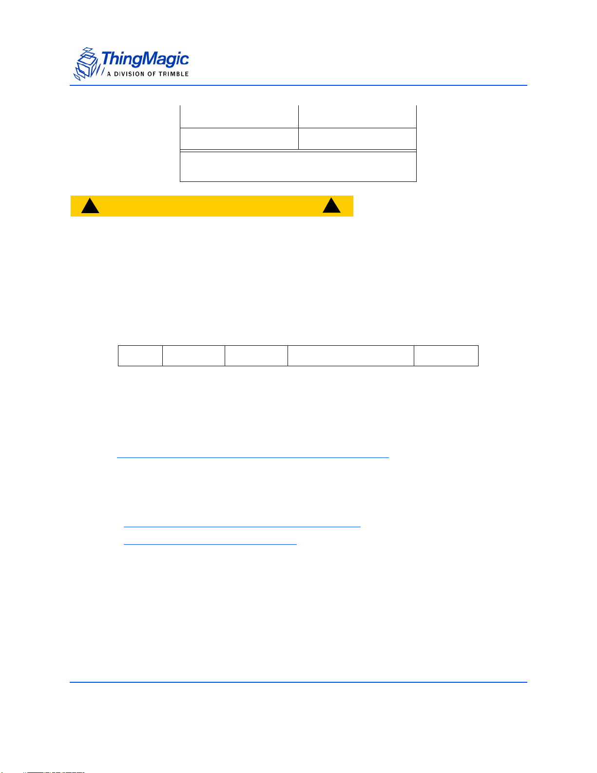
Boot Loader Commands
460800
921600
1
1
0x00070800
0x000E1000
Note: 1 - 460800 and 921600 cannot be used in
bootloader mode, only application mode.
!
CAUTION!
!
When using the 921600 baud rate you must pass an extra byte of data
(0x00) at the end of each message, after the CRC. This is due to a timing
issue. If the extra byte is not passed the message will not be processed
until the another byte of data is received.
In the following example, the baud rate is specified as a 32-bit value. This example sets
the baud rate to 115200:
FF 04 06 00 01 C2 00 A4 60
SOH Length OpCode Baud Rate CRC
The response to baud rate change is sent at the baud rate that the Set Baud Rate
command was transmitted. Once the baud rate has changed, the new rate is in effect until
the baud rate is changed by power cycling the reader.
Note
The baud rate reverts back to 9600 bps at power-up.
Error Status Codes
FAULT_MSG_WRONG_NUMBER_OF_DATA – 100h
FAULT_INVALID_BAUD_RATE - 10Ah
Verify Image CRC (08h)
After uploading a new application firmware image, the application CRC can be checked
with the Verify Image CRC command. The application CRC is already embedded in the
firmware image, so this command calculates the firmware’s CRC in flash and compares it
to the pre-stored value. It returns a fault code if the application firmware fails the CRC
70 Command Set
Page 71

Boot Loader Commands
checks. A failed CRC means that the application cannot run, and needs to be
downloaded again.
FF 00 08 1D 07
SOH Length OpCode CRC
The boot loader runs this command automatically before loading the application. If the
CRC check fails, the boot loader does not run the application to prevent corrupted code
from executing on the Microprocessor.
Error Status Codes
FAULT_MSG_WRONG_NUMBER_OF_DATA – 100h
FAULT_BL_INVALID_IMAGE_CRC – 200h
Start Bootloader (09h)
The Start Bootloader command shuts off the analog board and starts the boot loader
while inside the application. This is necessary to perform an upgrade of the firmware
while the system is running.
FF 00 09 1D 06
SOH Length OpCode CRC
Error Status Codes
FAULT_MSG_WRONG_NUMBER_OF_DATA – 100h
Command Set 71
Page 72
Boot Loader Commands
Get Current Program (0Ch)
The Get Current Program command returns a code for the current program being
executed in the module. These codes are defined as follows:
Code Program
0x11 M5e/M5e-C Bootloader
0x12 M5e/M5e-C Application
To get the current program command, send the following to the module:
FF 00 0C 1D 03
SOH Length OpCode CRC
The module responds as follows, indicating that it is a M5e/M5e-Compact application
program:
FF 01 0C 00 00 12 63 43
SOH Length OpCode Status Program CRC
Error Status Codes
FAULT_MSG_WRONG_NUMBER_OF_DATA – 100h
Write Flash Sector (0Dh)
The Write Flash Sector command is the same as the old Write Flash (01h) except it
has an extra flash sector argument. This allows future Mercury Embedded products to
work with the same command set.
FF 0F 0D 02 25 44 10 00 00 00 00 02 12 34 56 78 90 12 73 4C
SOH LengthOpCod
e
Password Start Address Sector Data To Write CRC
72 Command Set
Page 73

Boot Loader Commands
Error Status Codes
FAULT_MSG_WRONG_NUMBER_OF_DATA – 100h
FAULT_FLASH_ILLEGAL_SECTOR – 303h
FAULT_FLASH_BAD_WRITE_PASSWORD – 301h
Get Sector Size (0Eh)
The size of a flash sector can be retrieved from the module using the Get Sector Size
command. Since different products may have different flash sector sizes, this command is
useful for ensuring that the module has enough memory to store the desired data. This
example receives the sector size for the application area:
FF 01 OE 02 D1 BF
SOH Length OpCode Sector CRC
The response to this command on M5e is shown in the following example:
FF 04 OE 00 00 00 03 40 00 88 54
SOH Length OpCode Status Size of Sector CRC
The size of the sector is returned in bytes. For M5e, sector 2 (application) is 212992
bytes.
Error Status Codes
FAULT_MSG_WRONG_NUMBER_OF_DATA – 100h
FAULT_FLASH_ILLEGAL_SECTOR – 303h
Modify Flash Sector (0Fh)
The Modify Flash Sector command is the new version of the original Modify Flash
(0Ah) command. The following example writes 6 bytes to Sector 03.
FF 0F 0F 79 13 87 66 00 00 00 00 03 12 34 56 78 90 12 4C FA
SOH Length OpCode Password Start Address Sector Data To Write CRC
Command Set 73
Page 74

Error Status Codes
FAULT_MSG_WRONG_NUMBER_OF_DATA – 100h
FAULT_FLASH_ILLEGAL_SECTOR – 303h
FAULT_FLASH_BAD_ERASE_PASSWORD – 300h
Boot Loader Commands
74 Command Set
Page 75

Application Tag Commands
The application commands are used to interact with RFID tags in the field. These
commands can have slightly different behavior based upon the current protocol selected
in the system.
Applications Commands
Application Tag Commands
OpCode Command Name Bootloader
0x21
0x22
0x23
0x24
0x25
0x26
0x28
0x29
0x2A
0x2D
0x2E
Read Tag Single (21h)
Read Tag Multiple (22h)
Write Tag EPC (23h)
Write Tag Data (24h)
Lock Tag (25h)
Kill Tag (26h)
Read Tag Data (28h)
Get Tag Buffer (29h)
Clear Tag Buffer (2Ah)
Gen2 Tag Specific (2Dh)
BlockErase (2Eh)
NY
NY
NY
NY
NY
NY
NY
NY
NY
NY
NY
Tag Singulation/Select Functionality
App
Firmware
Many of the Gen2 tag commands now support the ability to singulate a specific tag or
inventory only tags matching a defined criteria, i.e. matching on values in the EPC, TID
and User Memory banks.
Select Algorithm and Parameters
The algorithm used to perform a Gen2 Select and its impact on subsequent Gen2 Query
operations on a population of tags is determined by several user defined settings which
either correspond directly to or are used to determine the various Gen2 Select and Query
Command Set 75
Page 76

Application Tag Commands
parameters as defined by the EPCGlobal Gen2 v1.2 Specification. The current user
controlled options are:
Gen2 Session (User Controlled)
This setting determines which tag inventory flag is altered when a tag responds to a Gen2
Query (each flag has a unique persistence profile, as defined by the Gen2 Specification).
The value of Gen2 Session and Gen2 Target is set using the Set Protocol Configuration
(9Bh) command.
Select Invert (User Controlled)
This setting is used to determine the Gen2 Action value sent in the Gen2 Select
command. The value of Select Invert is defined using bit 3 of the Select Option field in the
Tag Singulation Fields
. The supported values are:
0 (False) - Tags which match the Select criteria are to respond. Set Gen2
Action=0.
1 (True) - Tags which DO NOT match the Select criteria are to respond. Set Gen2
Action=4.
The settings specified for Gen2 Session and Select Invert determine the settings within
the Select command which is sent before the corresponding Gen2 Query and the settings
in the subsequent Gen2 Query(s). These implicit settings used by the Gen2 Select are:
Gen2 Action (defined by Select Invert)
This parameter can be one of 8 values, as defined by the Gen2 specification, which
determine which of 4 possible flag actions (assert, de-assert, negate, or leave alone) will
be done if the criteria matches and, similarly, which of the 4 possible flag actions will be
done if the criteria does not match. Only two values are currently used:
0 - Assert (or put in state “A” for inventory flags) the target flag if there IS a match;
de-assert (or put in state “B” for inventory flags) the target flag if there IS
NOT a match.
4 - Assert (or put in state “A” for inventory flags) the target flag if there IS NOT a
match; de-assert (or put in state “B” for inventory flags) the target flag if
there IS a match
76 Command Set
Page 77

Application Tag Commands
Gen2 Target (User Controlled)
This setting determines which inventory flag or SL flag is going to have its state
determined by the matching algorithm. Currently always set to ‘4’, indicating the Gen2
Select command modifies a tag’s SL flag.
The following table defines the currently supported User Settings and the resulting
behavior of the Gen2 Select and Gen2 Query:
Gen2 Select and Query Behavior
User Settings Select Behavior Query Behavior Comments
• Gen2 Session =
0,1,2,3
• Invert = 0
• Gen2 Target = A,
B, A<>B, B<>A
• Gen2 Session =
0,1,2,3
• Invert = 1
• Gen2 Target = A,
B, A<>B, B<>A
Select Process
The following defines how the Select process works when attempting to select tags that
match a defined criteria:
1. The Reader issues a Select containing the desired tag memory values and
instructions for the tag to assert if its contents matches that specified in the request
(and, conversely, de-assert the SL flag if it does not match) as defined by the Tag
Singulation Fields. The de-assert will generally have no effect because the de-
asserted state is the default, but is helpful if tags still have their SL flag asserted from
a previous Select.
Gen2 Select Settings:
• Target = 4
• Action = 0
If tags match the criteria, put
their SL flag in the ‘Assert’ state;
and SL of non-matching tags
into the ‘De-assert’ state.
Gen2 Select Settings:
• Target = 4
• Action = 4
If tags match the criteria, put
their SL flag in the ‘De-assert’
state; and SL of non-matching
tages into the ‘Assert’ state.
Gen2 Query Settings:
• SEL = 3
• Target = [User Defined]
• Session = [User Defined]
Ask tags to respond if their SL
flag is in the ‘Assert’ state and
their session appropriate inventory flag is in the user defined
state (default is ‘A’). Once a tag
responds, it puts the inventory
flag in the opposite state
(default is ‘B’), preventing further matches until the inventory
flag’s
Flag Persistence Rules
changes it back.
Tag state persistence
before a Query is based
on SL flag persistence;
Tag state persistence
after a Query is based on
inventory flag corresponding to the Session
used.
– Tags that are selected, at this point, are not selected within a specific Session. The
persistence of their state depends entirely on that of the SL flag.
2. A Query is issued which specifies the flag settings which must match before a tag will
respond:
Command Set 77
Page 78

Application Tag Commands
– The SL flag must be asserted
– The Session flag (Target setting) for session 0, 1, 2, or 3 (specific Session value is
in the Query and depends on the reader’s Session setting) must be in the user
defined state (the default value is ‘A’).
3. Matching tags will respond to the Query, but after responding, will change their own
state in the following way:
– The Inventory flag corresponding to the Session specified in the Query will be
changed to the opposite state (A->B or B->A).
– The SL flag will remain asserted (per its ongoing Flag Persistence Rules
4. If subsequent indentical Queries are issued (identical to the first), this tag will remain
silent until the Flag Persistence Rules
state cause the flag to fall back into the ‘A’ state or vice-versa. At that point, the tag
will respond again (assuming that the persistence rules of the SL flag are still keeping
it in the ‘assert’ state). Unless the Target Value was set to search for A then B or B
then A, in which case tags will be re-inventoried when the reader changes the flag
value its searching for instead of waiting for the tag to put its tag back into the
opposite state.
for the inventory flag that was put into the ‘B’
)
Note
A search with Invert=1 specified will perform the same steps except in step
1 the tag will “de-assert if its contents matches that specified in the request
(and, conversely, assert the SL flag if it does not match) as defined by the
Tag Singulation Fields.”
Note
A Select will be performed once per antenna when Select is specified during
a Read Tag Multiple (22h) with multiple antennas configured.
Flag Persistence Rules
Session 0
Keeps state as long as tag is energized
Returns to default state as soon as the tag is no longer energized
Its state will often get reset during the course of executing a single command, for
example, between inventory rounds, or when there is a frequency hop, or when a new
antenna is selected during a Read Tag Multiple search. the result is that when the session
is set to ‘0’, all tags will respond to every appropriate Query, considerably lengthening the
time to inventory a large population of tags. Session 0 is typically used for operations
where a single tag is expected to be in the field, for example, printers.
78 Command Set
Page 79

Application Tag Commands
Session 1
Keeps its state between 0.5 and 5 seconds, regardless of whether the tag is
energized or not.
The intent is that when the session is set to 1 the tag will respond to an appropriate Query
immediately, and then respond periodically if the Query is repeated by the reader. This
allows a larger population of tags to be reliable read. Session 1 is typically used in
applications where a large population of tags is being continuously inventoried allowing
for it to be determined when tags enter and leave the field.
Session 2, 3 and SL Flags
Keeps state as long as the tag is energized.
Keeps its state for at least 2 seconds after the tag is no longer energized and will
refresh its state if the tag is re-energized during that period.
The intent is that when the session is set to ‘2’ or ‘3’ a tag will only respond once to an
appropriate Query, then remain silent as the Query is repeated by the reader to elicit
responses from other tags. Typically used in operations when you are performing an
action on tag or population of tags which you do not want/need repeated.
Operations supporting Tag Singulation/Select
The commands currently supporting tag singulation through Select are:
Read Tag Single (21h)
Read Tag Multiple (22h)
Write Tag EPC (23h)
Write Tag Data (24h)
Lock Tag (25h)
Kill Tag (26h)
Read Tag Data (28h)
Gen2 Tag Specific (2Dh)
BlockWrite (2Dh)
BlockPermaLock (2Eh)
BlockErase (2Eh)
The addition of this functionality has added several (some conditional) fields to these
commands. The deprecated version of these commands are listed in Appendix D:
Command Set 79
Page 80

Application Tag Commands
Release Version 1.0.34. The command information in this section has been updated to only
include the new format.
The following fields have been added to all the specified commands. Please check each
command for exact order, and any exceptions, as they may not all correspond with the
order below.
Tag Singulation Fields
Field Values Description
Select Options
1
Select
Contents
(Bits 0,1, 2)
1
Select
Invert
(Bit 3)
1
Extended
Select Data
(Bit 5)
0x00 Select functionality is disabled. First tag found will be the tag
operated on. No other Tag Singulation Fields should be
specified. Option field must always be specified.
Note: When Select is disabled commands do not support
an access password. Use Select Option=0x05 to
send a password without Select.
0x01 Select on the value of the EPC. Requires all fields except
the Select Address field.
0x02 Select on contents of TID memory bank (Gen2 bank 0x02).
Requires all fields.
0x03 Select on contents of User Memory memory bank (Gen2
bank 0x03). Requires all fields.
0x04 Select on contents of the EPC memory bank (Gen2 bank
0x01). Requires all fields.
0x05 Use this option when you need to specify an access pass-
word to operation on locked data but don’t want to perform a
Select. When this option is used do not pass any Select Criteria.
0x08 Sets Invert Flag. This results in tags NOT matching the
specified Tag Singulation Fields will be returned, as defined
in
Select Algorithm and Parameters.
0x20 Changes Select Data Length to 2 bytes, allowing Select
Data to be greater than 255 bits.
80 Command Set
Page 81

Application Tag Commands
Field Values Description
The Select Options field is typically followed by command specific fields. After the command specific fields the following Tag Singulation fields should be specified as appropriate for the Select Contents specified.
Select Address 4 bytes Contains the offset, in bits, within the memory bank, speci-
fied by the Option value, at which the comparison is to start.
NOTE: specifying Option=0x04 and Select Address=0x20 is
the equivalent, for Gen2 v1 tags, of specifying Option=0x01,
both specify a comparison against the tag EPC ID data.
Note: Addresses are always zero-based. Specifying 0x00
indicates starting at the first address location.
Select Data Length 1 byte
(2 bytes if Extended
Data enabled)
Select Data M bytes Contains the data to be compared against the specified tag
Contains the length of the data (Select Data) to be compared, in bits, to the EPC when Option=0x01, or to the data
beginning at Select Address for other options.
data (memory bank and address, or EPC as specified by the
Option value)
The bit values used start at address 0. So if Select Data
Length = 2, i.e. matching 2 bits, then the bits used for comparision will be the 2 most significant bits of the Select Data
value. Examples:
Select Data = 0x00 the bits to match will be 0, 0
Select Data = 0x8F the bits to match will be 1, 0
This is independent of the Select Data Address field.
Note: 1- The Select Options field contains multiple sub fields which must be combined into a single Select Options
value. This means the final Select Options value is a result of Select Invert + Select Contents.
Example:
The following EPC IDs (first 3 bits) are in the field:
0xAAAA (101)
0xCCCC (110)
0x4444 (010)
0x3000 (001)
Select Option = 0x04 (EPC Mem Bank)
Select Data Length = 0x01 (1 bit)
Select Data = 0x80
Select Data Address = 0x00000022 (third bit in the EPC ID)
In this case the third bit of the EPC ID is matched against the first bit of the Select
Data value, 1. This would result in the following IDs being returned:
0xAAAA
0x3000
Command Set 81
Page 82

Application Tag Commands
Gen2 Memory Map
When performing a Tag Singulation/Select most of the criteria specifies values of data in
certain locations in a Gen2 tag’s memory map. The following is a logical view of the Gen2
memory map from the Generation2 Protocol v1.2 that can be used for reference when
trying to determine the memory address you are trying to match on:
Gen2 Tag Memory Map
Note
The address values specified in the memory map are hexidecimal, zero-
based bit offset within each memory bank (i.e. the PC section of the EPC
memory bank starts at bit 0x10, decimal 16, and runs to bit 0x1F, decimal
31). It is important to note the units used in various command fields for
address locations. In some cases the address is specified in words (16 bit
chunks), sometimes bytes (8 bit chunks) and sometimes bits.
82 Command Set
Page 83

Application Tag Commands
Read Tag Single (21h)
For deprecated version (including non-Gen2 protocol specific syntax) of this command
see Appendix D: Read Tag Single (21h)
The Read Tag Single command will search for a tag for the specified timeout or a single
tag is found, whichever comes first. The search criteria is specified using the Tag
Singulation Fields. If Option=0x00 is specified it will return with the first tag it finds,
otherwise it will only return Success and the found EPC if a tag matching the specified
criteria is found. If no tag is read, a fault code is returned.
In addition to the Tag Singulation Fields the basic Read Tag Single command takes a 16bit timeout value in milliseconds. The command will return after a tag is found or the
timeout expires, whichever happens first.
The basic syntax which returns only the tag EPC is defined in Get Tag EPC
additional Option bits set Read Tag Single can also return Tag Read Meta Data
syntax in Get Tag EPC and Meta Data
.
. With
using the
Note
Read Tag Single will always use Gen2 Q=0 when Get Protocol Configuration
(6Bh) Q Value set to Dynamic Q. For use with large tag populations a Static Q
appropriate for the population should be used to avoid collisions.
Get Tag EPC
The following example shows a search requesting a tag matching the following criteria for
a max timeout of 1000 ms. This example uses the Tag Singulation/Select Functionality
Option=0x03, indicating Tag Selection based on the contents of User Memory,
specifically:
Memory Bank = User Memory.
Starting Address = bit 32
Select Data = 0x1234
with
Command Set 83
Page 84

Application Tag Commands
FF 0A 21 03 E8 03 00 00 00 20 10 12 34 E5 AC
SOH Length OpCode Timeout (ms) Option Select Address Select
Data
Length
Select Data CRC
If Option=0x00 or 0x01 were used then the unused Tag Singulation Fields must be
removed from the request.
The response to this command varies depending upon the number of bits in the tag EPC
of the tag found. The general response format is shown here:
FF M+3 21 00 00 03 M bytes ?? ?? ?? ??
SOH Length OpCode Status Option EPC TagCRC CRC
Get Tag EPC and Meta Data
In addition to getting the tag EPC value returned you can also get Tag Read Meta Data for
the found tag. This version of Read Tag Single requires bit 4 of the Option flag to be set
and takes an additional Metadata Flags field which defines what metadata will be
returned The following table lists the supported values for these fields.
84 Command Set
Page 85

Application Tag Commands
Read Tag Single Get EPC and Metadata Request Fields
Field Value Description
Option Bit 4=0
(0x0X)
Bit 4=1
(0x1X)
Metadata Flags
(to specify more
than one OR
the values
together)
0x0000 When no flags are set no meta data will be returned, only the tag
0x0001 When bit 0 is set the Read Count will be returned
0x0002 When bit 1 is set the LQI/RSSI will be returned
0x0004 When bit 2 is set the Antenna ID will be returned
0x0008 When bit 3 is set the Frequency will be returned
0x0010 When bit 4 is set the Timestamp will be returned
0x0020 When bit 5 is set the RFU (ThingMagic Only) will be returned
0x0040 When bit 6 is set the Protocol ID will be returned.
0x0080 When bit 7 is set Tag Data information will be returned. (0x0000
No Metadata flags are specified and Meta Data will not be
returned. This is the
specified as defined by
Indicates that Metadata flags are to follow and the corresponding
Metadata shall be returned with the tag EPC. The lower bits (X)
are specified as defined by
Get Tag EPC syntax. The lower bits (X) are
Tag Singulation/Select Functionality.
Tag Singulation/Select Functional-
ity.
EPC (including the tag CRC)
is always returned for Read Tag Single)
These fields are followed by the
defined in the Get Tag EPC
Tag Singulation/Select Functionality, used the same as
syntax, if necessary.
A response can contain the following information:
Command Set 85
Page 86

Application Tag Commands
Read Tag Single Get EPC and Metadata Response Fields
Field Length Value
SOH 1 byte 0xFF
Length 1 byte Based on data returned
OpCode 1 byte 0x21
Status 2 bytes Status of command
Options 1 byte As sent in request
Metadata Flags 2 bytes Metadata contained in response
Read Count
RSSI
1
Antenna ID
1
1
1 byte Tag EPC/Antenna Read Count
1 byte Return Signal Strength Indicator
1 byte Antenna ID, 4 MSBs for TX and 4
LSBs for RX
Frequency
Timestamp
RFU
1
1
1
3 bytes Frequency in kHz
4 bytes RTC Timestamp
2 bytes Reserved for Future Use - ThingMagic
Only
Protocol ID 1 byte Protocol ID of tag (always 0x05 for
M5e/M5e-C)
Tag Data Length 2 bytes Size of tag data to follow. Always
0x0000 for Read Tag Single
EPC ID N bytes Tag EPC.
Tag CRC 2 bytes Tag EPC CRC
CRC 2 bytes Message CRC
1 - Conditionally returned depending on the Metadata Fields specified in the request.
Examples
An example command requesting AntennaID and Timestamp
86 Command Set
Page 87

Application Tag Commands
Metadata Flags = 0x0004 OR 0x0010 = 0x0014
with no tag singulation criteria, just return the first tag found, is as follows:
FF 05 21 01 E8 10 00 14 2F 6D
SOH Length OpCode Timeout Options Metadata Flags CRC
Here is an example response to the example request specified above. The response
contains the tag EPC info of the found tag and the requested tag read metadata:
AntennaID and Timestamp:
FF 16 21 00 00 10 00 14
SOHLength OpCodeStatus Options Metadata
11 00
Ant
ID
B
5F 04 01 23 45 67 89
B
Timestamp Tag EPC Tag CRC
Flags
ABC
37 C4
CRC
EF 01 23 45 67 E6 C8
D
Here is another example request and response showing the use of Tag Singulation/Select
Functionality and getting the tag metadata for the specified tag. Note the Options Field
includes the Select Options and bit 4 is set indicating the Meta Data flags follow.
This command requests the same tag read metadata as the previous example
(AntennaID and Timestamp) except now it is selecting a tag with a specific EPC value
(EPC=0x111122223333444455556666), which requires adding the appropriate Tag
Singulation Fields after the Read Tag Single Get EPC and Metadata Request Fields along with
Command Set 87
Page 88

Application Tag Commands
updating the Option field to set the appropriate flag for the tag singulation based on EPC
value
FF 12 21 01 E8 11 00 14
SOH Length OpCode Timeout Options Metadata Flags
60 11 11 22 22 33 33 44 44 55 55 66 66
Select
Data
Length
Select Data (EPC) CRC
9F
C
E
The response contains the requested metadata and the tag EPC matching the requested
tag EPC:
FF 16 21 00 00 11 00 14
SOHLength OpCodeStatus Options Metadata
22 0F C8 CD B7 11 11 22 22 33 33 44 44 55 55 66 66 18 35
Ant
ID
Timestamp Tag EPC Tag CRC
Flags
FE 7D
CRC
Error Status Codes
FAULT_MSG_WRONG_NUMBER_OF_DATA – 100h
FAULT_MSG_INVALID_PARAMETER_VALUE - 105h
FAULT_NO_PROTOCOL_DEFINED – 401h
FAULT_AFE_NOT_ON – 405h
FAULT_NO_TAGS_FOUND – 400h
FAULT_ANTENNA_NOT_CONNECTED – 503h
FAULT_TEMPERATURE_EXCEED_LIMITS – 504h
FAULT_HIGH_RETURN_LOSS – 505h
88 Command Set
Page 89

Application Tag Commands
Read Tag Multiple (22h)
For deprecated version of this command see Appendix D: Read Tag ID Multiple (22h)
The Read Tag Multiple command supports several different levels of functionality. In
addition to performing a Basic Search Operation for all tags in the field it can also perform
advanced searching and perform operations on the tags found. The different syntax for
Read Tag Multiple are defined as follows:
Basic Tag Inventory - Searches for and returns all tags in the field.
Tag Invento ry with Select - Searches for and returns all tags in the field meeting Select
criteria as defined by Tag Singulation Fields
Tag Inventory With Embedded Operations - Allows for operations (Write Tag Data, Lock
Tag, Kill Tag, Read Tag Data) to be performed on each tag inventoried.
Note
A Read Tag Multiple command will return early if it fills up the Tag Buffer
before the timeout has expired. This will not result in an error. If a Read Tag
Buffer command is issued with an already full Tag Buffer an error will be
returned.
specified.
Basic Tag Inventory
The Read Tag Multiple command performs a search for the specified period of time then
returns the number of tags that have been found. Afterwards, multiple Get Tag Buffer
commands can be sent to receive the found tag EPCs along with tag read metadata,
including the antenna the tag was read on. The command allows the user to specify the
method to use when multiple antennas are configured and connected along with
indicating the command contains embedded commands:
Command Set 89
Page 90

Read Tag Multiple Search Flags
Application Tag Commands
2
Flag Value
Antenna Usage
(bits 0, 1, 2)
Embedded Command
(bit 3)
Description
0x0000 Use single antenna as configured by the most recent Set
Antenna command.
1
0x0001
1
0x0002
1
0x0003
Automatically search on both monostatic antennas, start-
ing with Antenna 1. The search cycles through antennas
moving to the next antenna when no more tags are found
on the current antenna. It stops when the search timeout
expires.
Automatically search on both monostatic antennas, start-
ing with Antenna 2. The search cycles through antennas
moving to the next antenna when no more tags are found
on the current antenna. It stops when the search timeout
expires.
Automatically searches on all configured logical antennas,
using the Search Order defined using
Set Multi-Antenna
Search Configuration. The search cycles through anten-
nas, in the order specified, moving to the next antenna
when no more tags are found on the current antenna. It
stops when the search timeout expires.
0x0004 An embedded command is specified in the request and
will be executed on each inventoried tag.
Note: This bit should only be set when using the Tag
Inventory With Embedded Operations syntax.
Note: 1- Only one of these flags should be set since both Antenna 1 and 2 cannot be the starting antenna.
2 -Multiple Flags can be set (perform a binary OR) to specify different behaviors. ex: Search Flags = 0x0006
indicates a multiple antenna search starting on antenna2 is to be performed and the embedded command
specified is to be executed on each tag.
Note: When performing multi-antenna searches and Tag Singulation/Select Functionality is used, the
Select operation will be performed once per antenna. More specifically, during a single
with Select operation a Select will be issued at the start of searching on each antenna in use. If the
search comes back around to an antenna during the same command the Select is not issued again.
Tag In ventory
90 Command Set
Page 91

Application Tag Commands
Examples
For example, the syntax for a Read Tag Multiple with automatic multi-antenna search
starting with antenna1 is:
FF 04 22 00 01 03 E8 3F 8E
SOH Length OpCode Antennas Flag Timeout (ms) CRC
The response format for both is the following:
FF 01 22 00 00 02 46 BA
SOH Length OpCode Status # Tag IDs Found CRC
Tag Inventory with Select
If you want to inventory only tags meeting a specific criteria this syntax should be used.
The search criteria is specified using the Tag Singulation Fields
it will perform the same search as the Basic Tag Inventory
the number of tags found matching the specified criteria. The tag EPCs and Meta Data
will be available in the Tag Buffer. If no tags are found, a fault code is returned. The
required fields are as follows:
. If Option=0x00 is specified
syntax. Otherwise, it will return
Read Tag Multiple with Select Fields
Field Value Description
Select Options [1 byte]
Search Flags [2 bytes]
Timeout [2 bytes] Indicates how long the command should spend
Access Password [4 bytes]
The Options value of the
Read Tag Multiple Search Flags indicating antenna
usage. Bit 3 must be 0, no embedded commands.
searching.
The Access Password is only used with
Tag Singulation Fields
Tag Inven-
tory With Embedded Operations for the embedded
command. With this syntax it should be specified as
0x00000000.
Note: If Select Options=0x00 this field should be
omitted.
Tag Singulation Fields
The remaining, appropriate fields depending on the
value of Select Options.
Command Set 91
Page 92

Application Tag Commands
Examples
Here is an example request and response showing the use of Tag Singulation/Select
Functionality to inventory tags which meet a specific criteria:
This command will inventory all tags with an EPC value ending in 0x66, which requires
adding the appropriate Tag Singulation Fields
FF 0F 22 04 00 00 03 E8
to the Basic Tag Inventory syntax
SOH Length OpCode Options
(EPC Mem)
00 00 00 00 00 00 00 78 08 66
Access Password Select Address (bits) Select
Search Flags Timeout
Data
Length
(bits)
Select
Data
D
E
C0
CRC
Note
The Select Options field of the Tag Singulation Fields in the request is specified
at the beginning of the command followed by the Search Flags, Timeout,
Access Password then the rest of the Tag Singulation Fields. This is different
than the typical format for Select fields. Also, this syntax always requires an
Access Password be specified. Since only Reserved Memory can be read
locked and Reserved Memory cannot be used for singulation the Access
Password must be 0x00000000
The response contains the number of tags found matching the Select criteria specified.
Use G
FF 04 22 00 00 04 00 00 02 B7 6E
et Tag Buffer (29h) to access the tag EPCs and Tag Read Meta Data:
SOH Length OpCode Status Options
(EPC Mem)
Search Flags Tag Found CRC
Tag Inventory With Embedded Operations
In addition to inventorying tags, Read Tag Multiple can be used to perform an operation
on each tag in a population of tags. Starting with the Tag In ventory with Sele ct
define the population of tags the operation is to be performed on, the Search Flag bit 3
(0x0004) can be set to indicate embedded commands are to be performed on the
inventoried commands. The required fields are as follows:
92 Command Set
syntax to
Page 93

Read Tag Multiple Embedded Command Fields
Field Value Description
Application Tag Commands
Select Options [1 byte]
Search Flags [2 bytes]
Timeout [2 bytes] Indicates how long the command should spend searching AND performing the embed-
Access Password [4 bytes] The Access Password of the tags expected to be inventoried for the embedded com-
The Options value of the
Bit 3 of the
embedded command(s).
ded command. It may be desirable to specify a longer timeout if a large number of tags
are likely to get the embedded command executed on them.
mand, if they are locked. If the tags are not locked specify 0x00000000.
Read Tag Multiple Search Flags must be set indicating this request contains
Tag Singulation Fields
Note: If operating on locked tags, only tags which meet the Select criteria and
matching passwords will get a successful execution of the embedded command.
Note: If Select Options=0x00 this field should be omitted.
Tag Singulation Fields
Embedded
Command Count
Embedded
Command Length
Embedded
Command OpCode
[1 byte] The number of embedded commands to follow. [Only one allowed]
[1 byte] Length of embedded commands. Follows standard Length value calculation: number of
[1 byte] The OpCode of the embedded command. Currently supports:
The remaining, fields depending on the value of Select Options.
bytes after OpCode.
•
Write Tag EPC (23h)
• Write Tag Data (24h)
• Lock Tag (25h)
• Kill Tag (26h)
• Read Tag Data (28h)
• Gen2 Tag Specific (2Dh)
• BlockWrite (2Dh)
• BlockPermaLock (2Eh)
• BlockErase (2Eh)
When embedding Read Tag Data the complete set of data requested is returned for the
first tag that responds with the command response, but up to the first 32 bytes of data
requested is returned for every tag that responds and is stored in the tag buffer with the
other metadata. See
Example with Embedded Read Tag Data below for details.
The fields and values required
by the embedded command.
Command Set 93
The embedded commands do not support Tag Singulation as it is already performed
during the inventory operation. The Options field for the embedded command must be
0x00.
Note: The Timeout field for embedded commands must be 0x0000.
Page 94

Application Tag Commands
Read Tag Multiple Embedded Response Fields
Field Value Description
Status [2 bytes] Error Code if command failed, otherwise 0x0000 for Success
Select Options [1 byte] Options set in the Request Command
Search Flags [2 bytes] Search Flags set in the Request Command
Tags Found [1 byte]
Embedded Command Count [1 byte] The number of embedded commands to follow. [Currently only sup-
Embedded Command OpCode [1 byte] The OpCode of the embedded command as specified in the request
Operations Succeeded [2 bytes] Number of Embedded command operations which succeeded.
Number of tags found and added to the
criteria. Follows the standard criteria of adding tags the Tag Buffer. if
the Tag Buffer already has tags in it they will not be counted towards
Tags Found. However, if they match the Select Criteria they will have
the operation performed on them. For this reason it is important to
always make sure the Tag Buffer is clear before any Read Tag Multiple execution to insure accurate response information.
ports one]
command.
Tag Bu ffer matching Select
Note: Depending on the Gen2 Session/User Mode used the
Operations Succeeded/Failed counts can be misleading since
in Session 0, for example, the tag may respond many times
during an inventory round and the command may be
attempted many times. This would result in counts higher than
the actual number of tags the operation succeeded or failed
on.
Operations Failed [2 bytes] Number of Embedded command operations which failed.
Note: As noted above this number can be indicating the command
failed multiple times on the same tag. These values should be
used in combination with Tag Found and checking the Tag
Buffer to insure the operation was completed on the desired
tags.
The fields and values returned by the embedded command.
Example with Embedded Write Tag Data
Here is an example request and response showing the use of Tag Singulation/Select
Functionality to inventory tags which meet a specific criteria and then setting the Access
password on each using Write Tag Data (24h)
as an embedded command:
This command will inventory all tags with an EPC value ending in 0x34, which requires
adding the appropriate Tag Singulation Fields
to the Basic Tag Inventory syntax then will use
94 Command Set
Page 95

Application Tag Commands
Write Tag Data (24h) to write 0x12345678 into the Reserved Memory Bank starting at
Word address 0x00000002 (Access Password)
FF 1E 22 04 00 04 03 E8
SOH Length OpCode Options
01 0C 24
Embd
Cmd
Count
Embd
Cmd
Lengt
h
(EPC Mem)
Embd
Cmd
OpCod
e
Search
Flags
00 00
Embd Cmd
Timeout
(Not Used)
Timeout Access Password Select Data Address
00 00 00 00 02 00 12 34 56 78
Embd
Cmd
Options
(Must be
0x00)
00 00 00 00 00 00 00 78 08 34
Write Address (Words) Write
MemBank
(bits)
Write Data CRC
Select
Data
Length
(bits)
Select
Data
AF 29
The response contains the number of tags found matching the Select criteria specified
and the number of embedded command operations which succeeded and failed. Use G
et
Tag Bu ffer (2 9h) to access the tag EPCs and Tag Read Meta Data for the Tags Found.
Tags in the buffer may or may not have had successful execution of the embedded
command on them:
FF 0A 22 00 00 04 00 04 02 01 24 00 02 00 00 FF 5E
SOH Length OpCod
e
Status Options Search Flags Tag
Found
Embd
Cmd
Count
Embd
Cmd
OpCode
Operations
Succeeded
Operations
Failed
CRC
Note
Depending on the Gen2 Session/User Mode used the Operations
Succeeded/Failed counts can be misleading since in Session 0, for
example, the tag may respond many times during an inventory round and
the command may be attempted many times. This would result in counts
higher than the actual number of tags the operation succeeded or failed on.
The above commands were run in User Mode = Portal.
Note
When embedding write operations, including Lock and Kill, in Read Tag
Multiple the Read TX Power will be used for the entire operations: inventory
and the write. The power will not switch to the Write TX Power for each Write
operation.
Command Set 95
Page 96

Application Tag Commands
Example with Embedded Read Tag Data
When using Read Tag Multiple with an embedded Read Tag Data command an extra field
containing the requested Data from the first tag which responded matching the Select
criteria is added to the response. Up to 4 bytes of tag data for the other tags responding,
if any, is available as Tag Read Meta Data
simply using just a Read Tag Data with Select of being able to identify other tags
matching the criteria which still may need to be written or which you didn’t expect to
match. An example of sending an embedded Read Tag Data and its response is as
follows:
This command will inventory all tags with an EPC value ending in 0x34, which requires
adding the appropriate Tag Singulation Fields
Read Tag Data (28h)
to verify that 0x12345678 was written into the Reserved Memory
Bank starting at Word address 0x00000002 (Access Password):
. This command provides the added benefit over
to the Basic Tag Inventory syntax then will use
FF 1B 22 04 00 04 03 E8
SOH Length OpCode Options
(EPC Mem)
01 09 28
Embd
Cmd
Count
Embd
Cmd
Lengt
h
Embd
Cmd
OpCod
e
Search
Flags
Timeout Access Password Select Data Address
03 E8
Embd Cmd
Timeout
(Not Used)
00 00 00 00 00 00 00 78 08 34
(bits)
00 00 00 00 00 02 02
Embd
Cmd
Options
(Must be
0x00)
Read
MemBank
Read Address (Words) Read
Word
Count
Select
Data
Length
(bits)
The response contains the number of tags found matching the Select criteria specified
and the number of embedded command operations which succeeded and failed. Use G
Tag Bu ffer (2 9h) to access the tag EPCs and Tag Read Meta Data for the Tags Found.
Tags in the buffer may or may not have had successful execution of the embedded
command on them:
FF 0e 22 00 00 04 00 04 03 01 28 00 01 00 00
SOH Length OpCod
e
Status Options Search Flags Tag
Found
Embd
Cmd
Count
Embd
Cmd
OpCode
Operations
Succeeded
Select
Data
71 FE
CRC
et
Operations
Failed
11 22 33 44 DE 02
Data Read CRC
96 Command Set
Page 97

Application Tag Commands
Example with Embedded Kill Tag
This command will inventory all tags with an EPC value with the first 88bits equal to
0x30940425C4C1967400004E, which requires adding the appropriate Tag Singulation
Fields to the Basic Tag Inventory syntax then will use Kill Tag (26h) to kill all matching tags,
assuming they have their Kill password set to 0x12345678:
FF 20 22 01 00 04 00 FA
SOH Length OpCode Options
(EPC Mem)
01 08 26
Embd
Cmd
Count
Embd
Cmd
Lengt
h
Search
Flags
Embd
Cmd
OpCod
e
Timeout Access Password Select
00 00
Embd Cmd
Timeout
(Not Used)
Note
If the tags being inventoried and operated on with the embedded command
have their Access Password set then the Access Password field must be set
accordingly, otherwise it can be left as zero.
The response contains the number of tags found matching the Select criteria specified and
the number of embedded command operations which succeeded and failed. Use G
Buffer (29h) to access the tag EPCs for the Tags Found. Tags in the buffer may or may not
have had successful execution of the embedded command on them:
87 65 43 21 58 30 94 04 25 C4 C1 96 74 00 00 4E
Data
Length
(bits)
00 12 34 56 78 00
Embd
Cmd
Options
(Must be
0x00)
Kill Password RFU CRC
Select Data
5F C4
et Tag
FF 0a 22 00 00 01 00 04 01 01 26 00 02 00 00 D9 80
SOH Length OpCod
e
Status Options Search Flags Tag
Found
Embd
Cmd
Count
Embd
Cmd
OpCode
Operations
Succeeded
Operations
Failed
CRC
Note
In this example it shows the number of Tags Found lower than the
Operations Succeeded. This is because, as with any Read Tag Multiple
execution, if the Tag Buffer already has a specific tag in it, it will not be
counted towards Tags Found. However, because it matches the Select
Criteria it will have the operation performed on it. For this reason it is
important to always make sure the Tag Buffer is clear before any Read Tag
Multiple execution.
Command Set 97
Page 98

Error Status Codes
FAULT_MSG_WRONG_NUMBER_OF_DATA – 100h
FAULT_MSG_INVALID_PARAMETER_VALUE - 105h
FAULT_NO_PROTOCOL_DEFINED – 401h
FAULT_AFE_NOT_ON – 405h
FAULT_NO_TAGS_FOUND – 400h
FAULT_TAG_ID_BUFFER_FULL – 601h
FAULT_ANTENNA_NOT_CONNECTED – 503h
FAULT_TEMPERATURE_EXCEED_LIMITS – 504h
FAULT_HIGH_RETURN_LOSS – 505h
Write Tag EPC (23h)
Application Tag Commands
The Write Tag EPC command should be used when updating the EPC value of a tag. It is
preferred over using Write Tag Data (24h)
lengthen or shorten the EPC ID, by modifying the PC bits, according to the Tag EPC
specified. If Write Tag Data is used, the specified data will be modified but the EPC ID
length will not be modified.
because Write Tag EPC will automatically
Note
Write Tag EPC will always use Gen2 Q=0 when Get Protocol Configuration
(6Bh) Q Value set to Dynamic Q. For use with large tag populations a Static Q
appropriate for the population should be used to avoid collisions.
The Write Tag EPC command takes the following fields:
98 Command Set
Page 99

Application Tag Commands
Write Tag EPC Command Fields
Field Value Description
Length [1 byte] Number of bytes in the command following the OpCode.
OpCode 0x23 Write Tag EPC
Time Out [2 bytes] Command timeout in milliseconds.
Select Options [1 byte]
Access Password [4 bytes] The Access Password of the tags expected to be inventoried for the
The Options value of the
embedded command, if they are locked. If the tags are not locked
specify 0x00000000.
Tag Singulation Fields
Note: If operating on locked tags, only tags which meet the Select
criteria and matching passwords will get a successful
execution of the embedded command.
Note: If Select Options=0x00 this field should be omitted.
Tag Singulation Fields
Tag EPC ID [M bytes]
The reader sends a Fault Code / ACK response back to the host.
An example of Write Tag EPC command sequence of events and format is shown next:
1. Starts a timer on the reader.
2. Wakes the tag.
3. Programs the tag with the EPC ID
The remaining, fields depending on the value of Select Options.
Up to 496-bit (
S
et Reader Configuration(9Ah)) tag ID to write to the Tag
depending on EPC Length parameter setting in
4. Reads the tag and verifies if the write succeeded.
Note
The verify operation uses the same power level as the write operation. It
does not change to the Read power level.
5. Sends back an ACK if OK or a fault code for timeout or other faults.
FF 00 23 00 00 ?? ??
SOH Length OpCod
Command Set 99
e
Status CRC
Page 100

Application Tag Commands
Error Status Codes
FAULT_MSG_WRONG_NUMBER_OF_DATA – 100h
FAULT_MSG_INVALID_PARAMETER_VALUE - 105h
FAULT_NO_PROTOCOL_DEFINED – 401h
FAULT_AFE_NOT_ON – 405h
FAULT_NO_TAGS_FOUND – 400h
FAULT_ANTENNA_NOT_CONNECTED – 503h
FAULT_TEMPERATURE_EXCEED_LIMITS – 504h
FAULT_HIGH_RETURN_LOSS – 505h
Write Tag Data (24h)
For the deprecated version of this command see Appendix D: Write Tag Data (24h).
The Write Tag Data command writes to the specified memory bank and data address
location within that memory bank of a tag. The tag which will be written to can be
specified using the Tag Singulation Fields
specified, it will attempt to write to the first tag it finds. If no tag is in the field, the memory
location doesn’t exist or is unwriteable, or the Select criteria cannot be satisfied a fault
code is returned.
In addition to the Tag Singulation Fields the Write Tag Data command takes several fields
which specify the data which will be written to the tag. These fields are:
or, if Option=0x00 of the Tag Singulation Fields is
100 Command Set
 Loading...