


Mercury6(M6) and Astra-EX
User Guide
For firmware version 4.17 and later
875-0058-05 RevB
1

Government Limited Rights Notice: All documentation and manuals were developed at
private expense and no part of it was developed using Government funds.
The U.S. Governmentʼs rights to use, modify, reproduce, release, perform, display, or
disclose the technical data contained herein are restricted by paragraph (b)(3) of the
Rights in Technical Data — Noncommercial Items clause (DFARS 252.227-7013(b)(3)),
as amended from time-to-time. Any reproduction of technical data or portions thereof
marked with this legend must also reproduce the markings. Any person, other than the
U.S. Government, who has been provided access to such data must promptly notify
ThingMagic.
ThingMagic, Mercury, Reads Any Tag, and the ThingMagic logo are trademarks or
registered trademarks of ThingMagic, A Division of Trimble.
Other product names mentioned herein may be trademarks or registered trademarks of
Trimble or other companies.
©2013 ThingMagic – a division of Trimble Navigation Limited. ThingMagic and The
Engine in RFID are registered trademarks of Trimble Navigation Limited. Other marks
may be protected by their respective owners. All Rights Reserved.d
ThingMagic, A Division of Trimble
One Cambridge Center, 11th floor
Cambridge, MA 02142
866-833-4069
05 Revision B
November, 2013
2

Introduction 7
Hardware Overview 9
What’s in the Box 9
M6 Reader 9
Astra-EX Reader 9
Ports and Connectors 9
Antenna Connections 9
Ethernet/PoE 11
USB Accessory 11
Console 11
GPIO 11
DC Power 11
Reset Button 11
Contents
Programming Interfaces 13
MercuryAPI 13
Demo Applications 13
LLRP 13
On-Reader Applications 14
Setting Up the Reader 15
Equipment Required 15
Setup Procedure 16
Connecting Antenna(s) to the Reader 16
Powering Up the Reader 17
Interpreting the Reader Indicator LED 17
Connecting Your PC to the Reader 18
Communicating with the Reader using a Link-local Address 18
Logging On to the Reader 22
Networking the Reader 25
Setting Up the Network Hardware 25
3

Using the Wireless Network 26
Using Power Over Ethernet (PoE) 29
Using DHCP 30
M6 and Astra-EX Setup 30
PC Setup 30
Automatic Hostname: M6-xxxxxx or Astra-EX-xxxxxx 32
MAC Address 32
Fallback Interface Options 33
Fallback to the Same Physical Interface 33
Fallback to the Other Physical Interface 33
Reader Discovery 36
Using mDNS 36
Reader Listing 36
Identify Reader 37
Connecting to the USB Console Port 39
Using GPIO 40
Inputs 40
Outputs 40
Connector Pinout 41
Controlling the Reader 43
Using the Browser-Based Interface 43
Status Page 44
Query Page 45
Settings Page 50
Restart Page 57
Diagnostics Page 58
Statistics Page 59
Firmware Upgrade Utility 59
Using Safe Mode 61
Force M6 and Astra-EX to boot in safe mode 61
Advanced Reader Functionality 63
Protocol Support 63
ISO 18000-6C (Gen2) 63
ISO 18000-6B 64
Protocol Configuration Options 64
Tag Read Meta Data 64
Reader RF Power 66
Power Settings for Authorized Antennas and Cables 66
Setting the Reader RF Power 68
4

Mounting the Reader 69
M6 69
Astra-EX 69
Variables Affecting Performance 70
Environmental 70
Tag Considerations 71
Multiple Readers 71
M6 Specifications 72
UHF RFID Antenna Interface 72
Power 72
Environmental 73
Physical Dimensions 73
Supported UHF Tag Protocols 73
Data/Control/Wireless Interfaces 73
Performance 74
Regulatory & Safety 74
User Memory 74
Astra-EX Specifications 75
UHF RFID Antenna Interface 75
Power 75
Environmental 76
Physical Dimensions 76
Supported UHF Tag Protocols 76
Data/Control/Wireless Interfaces 76
Performance 77
Regulatory & Safety 77
User Memory 77
Compliance and IP Notices 78
Regulatory Compliance 78
Federal Communication Commission Interference Statement 78
Industry Canada 78
Appendix A: M6 and Astra-EX Antenna and Cable Information 81
Authorized Antennas 81
Authorized Cables 82
Appendix B: M6 and Astra-EX Dimensions 83
Appendix C: Advanced Administration 85
Changing the Web Interface uid/passwd 85
Changing console/root password: 86
Appendix D: Troubleshooting 87
5

Troubleshooting Table 87
Reset to the Default Configuration 88
Collecting Diagnostic Data for ThingMagic Support 88
Analyzing the Boot Logs 89
6

Introduction
This document assumes usage of an M6 and Astra-EX with firmware version 4.17 or later.
M6 and Astra-EX
User Guide
This document explains how to set up the Mercury6 (M6) and Astra-EX Readers, how to
configure themfor network operation, and how to use the browser-based interface. See
the corresponding M6 and Astra-EX Firmware Release Notes for operational differences
that what is in this User Guide specific to a firmware version.
Separate appendices contain specifications and antenna information that are specific to
the M6 and Astra-EX Reader.
Applications to control the M6 and Astra-EX can be written using the high level
MercuryAPI. The MercuryAPI supports Java, .NET and C programming environments.
The MercuryAPI Software Development Kit (SDK) contains sample applications and
source code to help developers get started demoing and developing functionality. For
more information on the MercuryAPI see the MercuryAPI Programmers Guide and the
MercuryAPI SDK, available on the ThingMagic website.
This document is broken down into the following sections:
Hardware Overview - Provides detailed specifications of the M6 and Astra-EX
hardware and physical interfaces.
M6 and Astra-EX User Guide 7

Introduction
Programming Interfaces - Describes the programming interfaces, including on-reader
applications, where to find code samples, and the LLRP interface.
Connecting to the M6 and Astra-EX - Describes the methods available for connecting
to the M6 and Astra-EX over the ethernet, WiFi and USB Console interfaces.
– Setting Up the Reader
Host PC to the M6 and Astra-EX.
– Networking the Reader
static IP settings.
- Connect using a direct ethernet connection from a
- Connect over ethernet LAN or WiFi using DHCP or
– Connecting to the USB Console Port
console for command-line interface access and troubleshooting.
- Connect to the M6 and Astra-EX
Using GPIO - Details the GPIO physical interface specs and how to control it via the
MercuryAPI.
Controlling the Reader - Describes the browser-based interface and the configuration
and testing options available through it.
Advanced Reader Functionality - Provides descriptions of the M6 and Astra-EX
advanced protocol specific configuration options that ares supported through the use
of the MercuryAPI
Reader RF Power - Provideds guidelines and limitations for setting the RF Power of
the M6 and Astra-EX.
Mounting the Reader and Appendix B: M6 and Astra-EX Dimensions - Provides
details of the physical dimensions of the M6 and Astra-EX.
M6 Specifications
Compliance and IP Notices
Appendix A: M6 and Astra-EX Antenna and Cable Information - Lists the authorized
Antennas and cables which can be used with the M6 and Astra-EX-NA in FCC
regions.
Appendix C: Advanced Administration - Provides the steps for some advanced
administration settings, such as changing reader passwords.
Appendix D: Troubleshooting - Provides recommended debugging steps for common
problems along with data to gather when submitting a problem case to ThingMagic
support.
M6 and Astra-EX User Guide 8

Hardware Overview
Whatʼs in the Box
M6 Reader
– M6 Reader
– WiFi antenna (with Wifi enabled M6 only)
– Ferrite Bead (to be applied when Using Power Over Ethernet (PoE)
Astra-EX Reader
– Astra-EX Reader
– WiFi antenna (with Wifi enabled Astra-EX only)
Hardware Overview
)
– Ferrite Bead (to be applied when Using Power Over Ethernet (PoE)
Ports and Connectors
Antenna Connections
The M6 supports four monostatic bidirectional RF antennas through four Reverse Polarity
TNC (RP-TNC or R-TNC) connectors: labeled RFID1 through RFID4 on the M6 - Figure
1.
The Astra-EX supports two monostatic bidirectional RF antennas through one integrated
antenna and one Reverse Polarity TNC (RP-TNC or R-TNC) connector: labeled RFID -
Figure 2.
The maximum RF power that can be delivered to a 50 ohm load from the external port is
1.4 Watts, or +31.5 dBm (regulatory requirements permitting).
The RF ports can only be energized one at a time.
)
M6 and Astra-EX User Guide 9
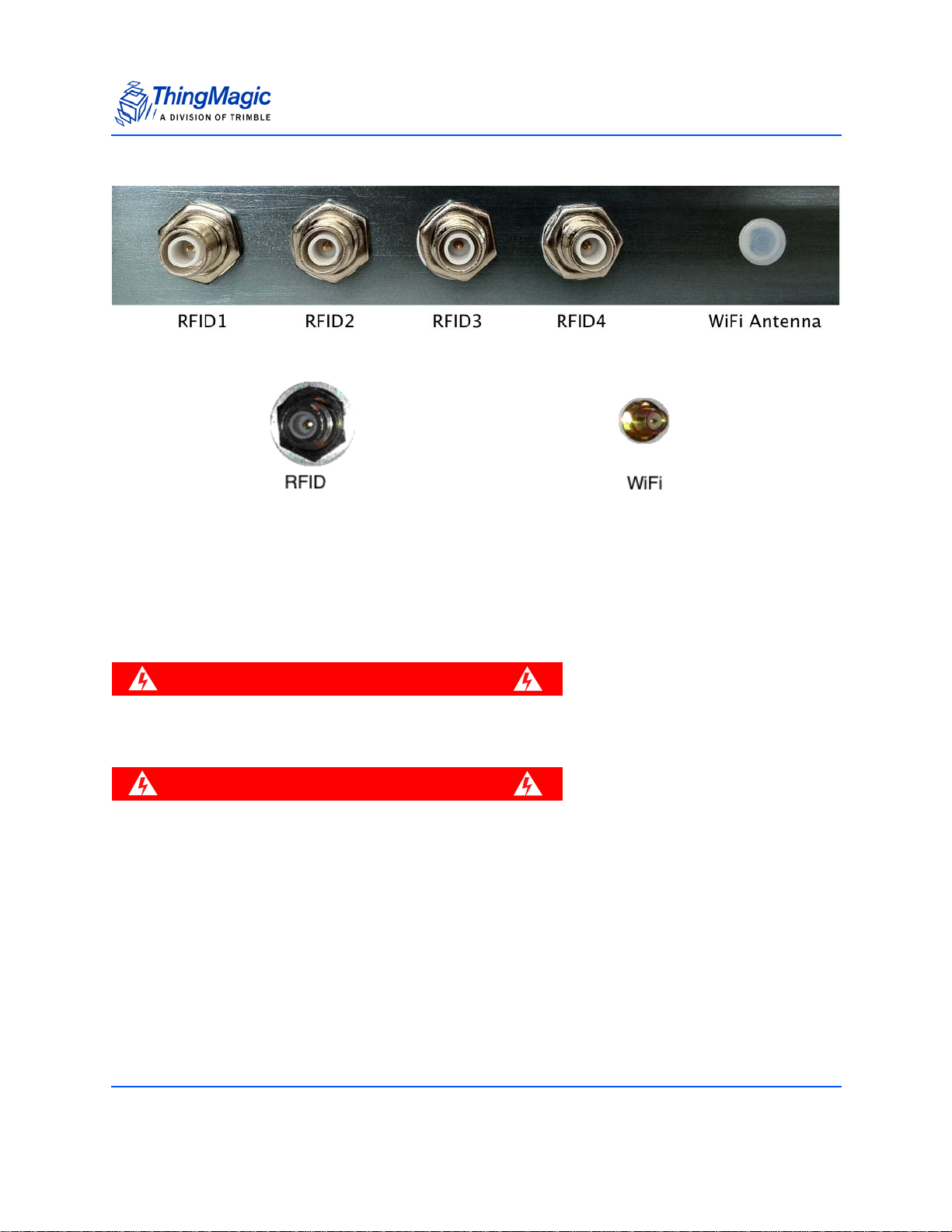
Figure 1: M6 RFID and WiFi Antenna Ports
WARNING!
WARNING!
Figure 2: Astra-EX RFID and WiFi Antenna Ports
Antenna Requirements
Hardware Overview
The performance of the M6 is affected by antenna quality. Antennas that provide good 50
ohm match at the operating frequency band perform best. Specified sensitivity
performance is achieved with antennas providing 17 dB return loss or better across the
operating band. Damage to the reader will not occur for any return loss of 1 dB or greater.
Damage may occur if antennas are disconnected during operation or if the M6
and Astra-EX sees an open or short circuit at its antenna port.
To comply with FCC’s RF radiation exposure requir ements, the antenna(s) used
for this transmitter must be installed such that a minimum separation distance
of 25cm is maintained between the radiator (antenna) & user’s/nearby people’s
body at all times and must not be co-located or operating in conjunction with
any other antenna or transmitter.
Antenna Detection
To minimize the chance of damage due to transmitting on open ports or antenna
disconnection, the M6 and Astra-EX supports antenna detection. Detection is performed
automatically at startup and before RF operations. In order to be detectable antennas
must present a DC resistance of ~10k Ohms or less.
M6 and Astra-EX User Guide 10
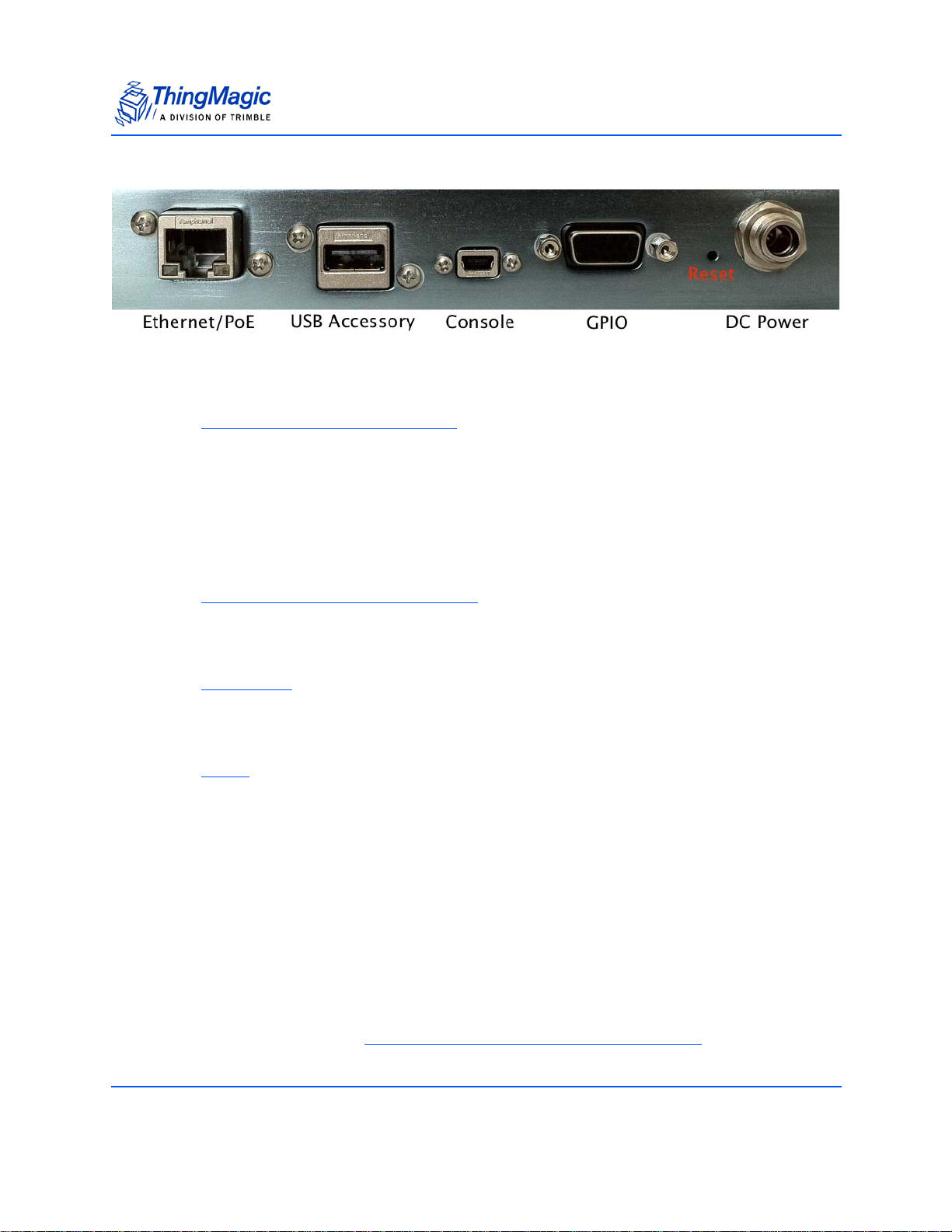
Figure 3: M6 and Astra-EX Digital Connectors
Ethernet/PoE
See Using Power Over Ethernet (PoE).
USB Accessory
Reserved for future use.
Hardware Overview
Console
See Connecting to the USB Console Port.
GPIO
See Using GPIO
DC Power
See Power for DC Power supply requirements. The connector used (Switchcraft Inc.
761KS12) has the following specifications:
– 2.5mm hollow center pin
– Lock Ring Thread Size: 7/16-32 UN2B thread
– Handle Thread Size: 5/16-24 UNF 2A
– Electrical: Current (carry) 5A at 65°C
– IP68 Rated
Reset Button
Using a non-conductive object press and hold for 2 seconds to perform a soft reset. Press
and hold for 4 seconds to Force M6 and Astra-EX to boot in safe mode
M6 and Astra-EX User Guide 11
. For dust and

Hardware Overview
moisture protection the Reset button is covered by a screw. To press the Reset the screw
must be removed.
M6 and Astra-EX User Guide 12

Programming Interfaces
MercuryAPI
Applications to control the M6 and Astra-EX reader, and all ThingMagic Reader products,
can be written using the high level MercuryAPI. The MercuryAPI supports Java, .NET and
C (for on-reader applications) programming environments. The MercuryAPI Software
Development Kit (SDK) contains sample applications and source code to help developers
get started demoing and developing functionality. For more information on the
MercuryAPI see the MercuryAPI Programmers Guide and the MercuryAPI SDK, available
on the ThingMagic website.
Demo Applications
The primary, “Quick Start”, demo for reading tags is the Query Page of the Web Interface.
For more advanced functionality, and also a starting place for building custom
applications, a demo application is provided in the MercuryAPI SDK package. The
executable for this example is included in the MercuryAPI SDK package (available on
rfid.thingmagic.com/devkit) under /cs/samples/exe/Universal-Reader-Assistant2.0.exe.
Programming Interfaces
LLRP
See the Universal-Reader- Assistant 2.0 User Guide (on rfid.thingmagic.com/devkit) for
usage details.
LLRP is the EPCglobal standard (http://www.epcglobalinc.org/standards/llrp/llrp_1_0_1-
standard- 20070813.pdf) used for communication between the M6 and Astra-EX and a
client application. The M6 and Astra-EX should be “drop-in compatible” with systems
supporting the standard LLRP protocol. Middleware such as BizTalk and WebSphere
have standard LLRP adapters that can work with the M6 and Astra-EX. In many cases
custom extensions are implemented to support non-standard configuration options and
commands, which are often reader specific. If your LLRP based client uses such custom
extensions it is likely that modifications will need to be made to support the M6 and AstraEX. In addition some M6 and Astra-EX functionality is only available through the use of
custom extensions.
For more information on direct use of LLRP, the ThingMagic custom extensions and the
open source LLRP ToolKit please contact ThingMagic support
(support@thingmagic.com).
M6 and Astra-EX User Guide 13

On-Reader Applications
The M6 and Astra-EX Reader, starting with firmware v4.9.2 and MercuryAPI v1.11.1 (FW
v4.17 and API v1.19 for Astra-EX), support running custom applications on the reader,
built using the MercuryAPI C Language interface. Most programs written using the C API
can be compiled to run as a client application or run on the reader.
Please see the MercuryAPI Programmers Guide | On-Reader Applications Guide,
available for download from http://rfid.thingmagid.com/devkit.
Programming Interfaces
M6 and Astra-EX User Guide 14

Setting Up the Reader
Note
This section describes the steps to setup all the necessary components and connect to
the Readerʼs browser-based interface.
Equipment Required
To set up Single Reader Operation, you need the reader and some additional hardware.
The additional hardware required includes:
A computer with a Java-enabled web browser
Ethernet cable (CAT5e, shielded, 5ʼ)
Wideband antenna(s) [not required for Astra-EX]
Coax cable(s) (with RP-TNC connectors) [not required for Astra-EX]
Setting Up the Reader
To install the M6 and Astra-EX Reader, no software is required.
To set up the Reader as part of a larger scale deployment that uses Wireless Network
(WLAN) connection or Power Over Ethernet (PoE), refer to Networking the Reader
.
M6 and Astra-EX User Guide 15

Setup Procedure
Note
The steps required to set up and run the M6 and Astra-EX Reader are:
1. Connecting Antenna(s) to the Reader
2. Powering Up the Reader
3. Connecting Your PC to the Reader
Setting Up the Reader
4. Communicating with the Reader using a Link-local Address
5. Logging On to the Reader
Connecting Antenna(s) to the Reader
The M6 Reader supports up to four monostatic antennas. The default power setting that
you configure is applicable to all antennas, although per-antenna settings are supported.
See Settings Page
Before you apply power to the Reader, you must connect at least one antenna to an RFID
antenna port. When the Reader is powered on, any port that is not connected and
meeting the Antenna Detection
Use only authorized antennas and cables. See Appendix A: M6 and Astra-EX
Antenna and Cable Information.
for configuration options.
requirements is disabled.
M6 and Astra-EX User Guide 16

Setting Up the Reader
Powering Up the Reader
You can power up the M6 and Astra-EX Reader using:
DC power supply - NOTE: Sold separately
Power over Ethernet (PoE) - NOTE: Required cable sold separately
To power up the M6 and Astra-EX Reader using a DC power supply:
1. Plug the power supply into the Reader's DC power input connector.
2. Connect the extension cord to the power supply and plug it into a 100-240VAC
power outlet. The Reader immediately begins to power up.
There is no on/off switch on the Reader. While the Reader is powering up, the
power LED is solid amber. The Reader is ready for operation after
approximately 60 seconds when the power LED changes to solid green.
To power-up the Reader using PoE, see Using Power Over Ethernet (PoE)
By default, if both DC power supply and PoE are provided to the M6 and Astra-EX
Reader, the Reader will use only the DC power supply as the source of power. In this
situation, if DC power is turned off, then the Reader requires a hard power cycle (a
software or reset button reboot are not sufficient) in order to function properly and use
PoE (even if it is already plugged in).
.
Interpreting the Reader Indicator LED
The M6 and Astra-EX Reader has one main multi-color LED that indicates Reader
activity. By observing the color and the state of the LED, you can determine the current
operational status of the M6 and Astra-EX Reader.
The colors displayed by the LED include:
Solid Amber: Indicates that the Reader is starting up.
Blinking Amber: Indicates reader is trying to aquire an IP address using
primary network configuration. If fallback address is being used LED may stay in
blinking state.
Solid Green: Indicates that the Reader has a valid IP address and is ready for
operation.
Blinking Green: Indicates that the RF field is ON and the unit is reading/writing
tags.
M6 and Astra-EX User Guide 17

Setting Up the Reader
Note
Solid Red: Indicates that there is a failure in the RFID subsystem.
Blinking Green/Red: Identify Reader function has been invoked. Should only be
in this mode for about 1 minute.
Additionally, when the Reader is connected to a PC or a network outlet, the two small
LEDs adjacent to the Ethernet (POE LAN) port indicate Network Status and Network
Activity.
Connecting Your PC to the Reader
You can provide network connectivity to the M6 and Astra-EX Reader using either
Ethernet or WIFI. For instructions on connecting the Reader to a network using WLAN or
PoE, see the section Networking the Reader
With a direct connection to a PC, with default/factory configuration the reader will use
Zero Configuration networking (also referred to as Automatic Private IP Addressing on
Windows) to get a link local address.
To connect your Reader directly to your PC:
.
1. Connect an Ethernet cable to your PC.
2. Connect the other end of the Ethernet cable to the Readerʼs POE LAN port.
Communicating with the Reader using a Link-local Address
If you are using an operating system other than Windows 7, consult your network
administrator regarding how to set up your PCʼs TCP/IP connection.
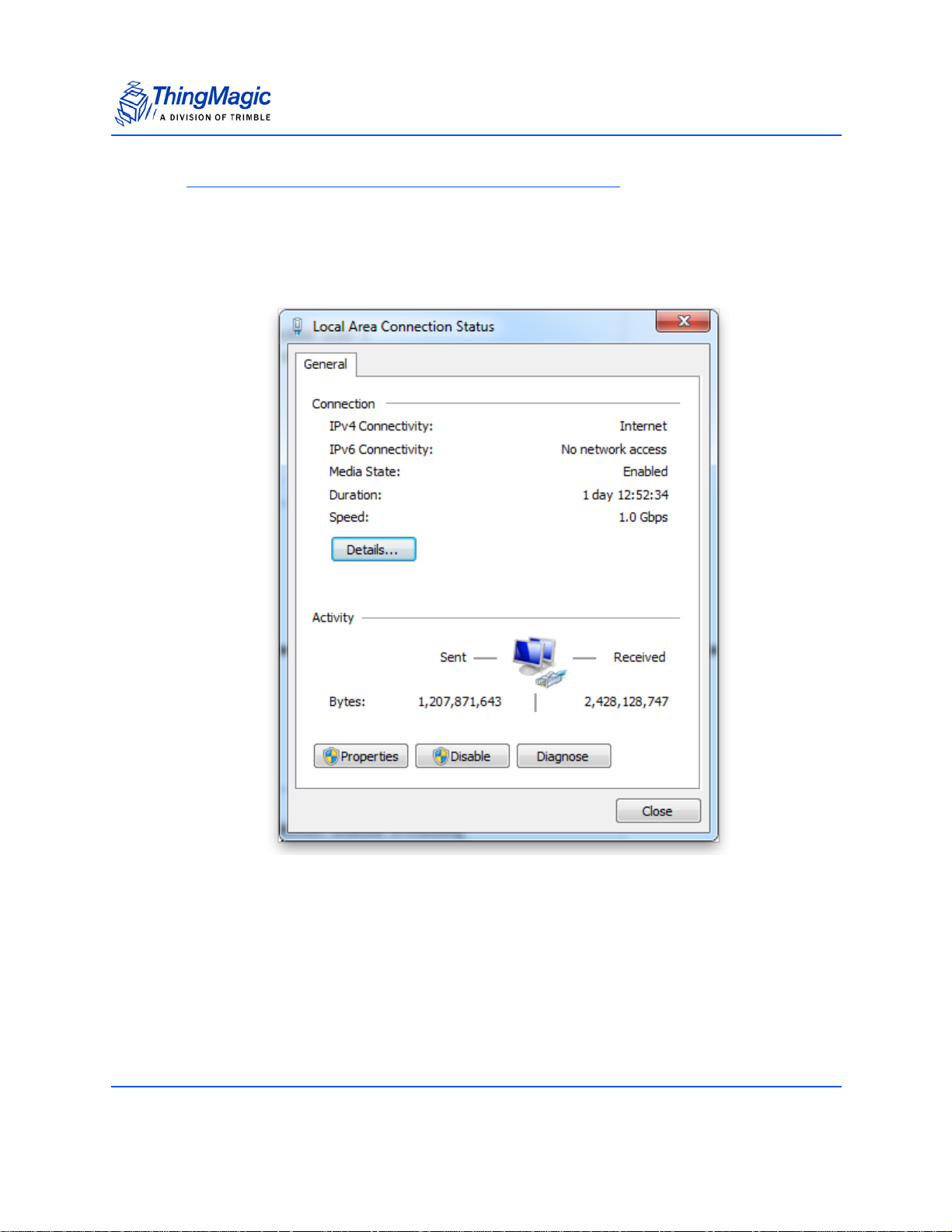
If you are using Windows 7, perform the following steps to set up (or verify) your PC's
TCP/IP connection. On most PCs this is the default configuration:
1. Select Start from the Start bar, and then select Control Panel.
2. Under Network and Internet, select “View network status and tasks”.
3. In the left menu select “Change adapter settings”.
4. The Local Area Connection Status window appears, as shown in Figure 4.
Link-local addressing does not work if DHCP is disabled on the reader. If the
readerʼs Network Settings
will not work.
have been modified to use a static IP address this setup
M6 and Astra-EX User Guide 18
Setting Up the Reader
Note
Previous M6 firmware, v4.9.3 and earlier, did not support link-local addressing. By
default the reader would fallback to a static IP address, 10.0.0.101, if a DCHP
server was not available. If this functionality is desired please contact ThingMagic
support for assistance in enabling it.
Figure 4: Local Area Connection Status Window
M6 and Astra-EX User Guide 19
Setting Up the Reader
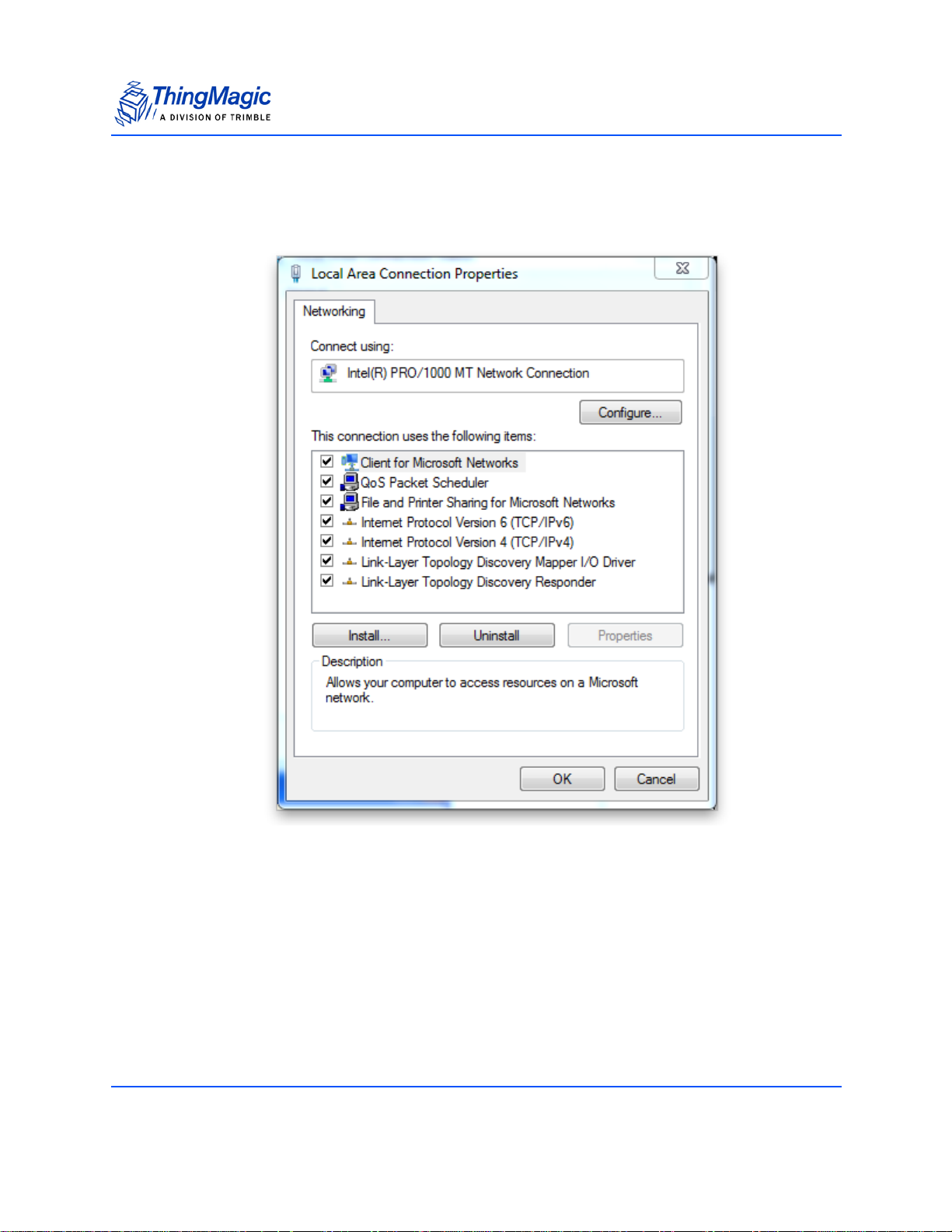
5. Click the Properties button.
The Local Area Connections Properties window appears, as shown in Figure 5.
Figure 5: Local Area Connection Properties Window
6. Scroll down and select the Internet Protocol (TCP/IP) version youʼre using. If you
donʼt know which, change both.
M6 and Astra-EX User Guide 20
Setting Up the Reader
7. Click on the Properties button.
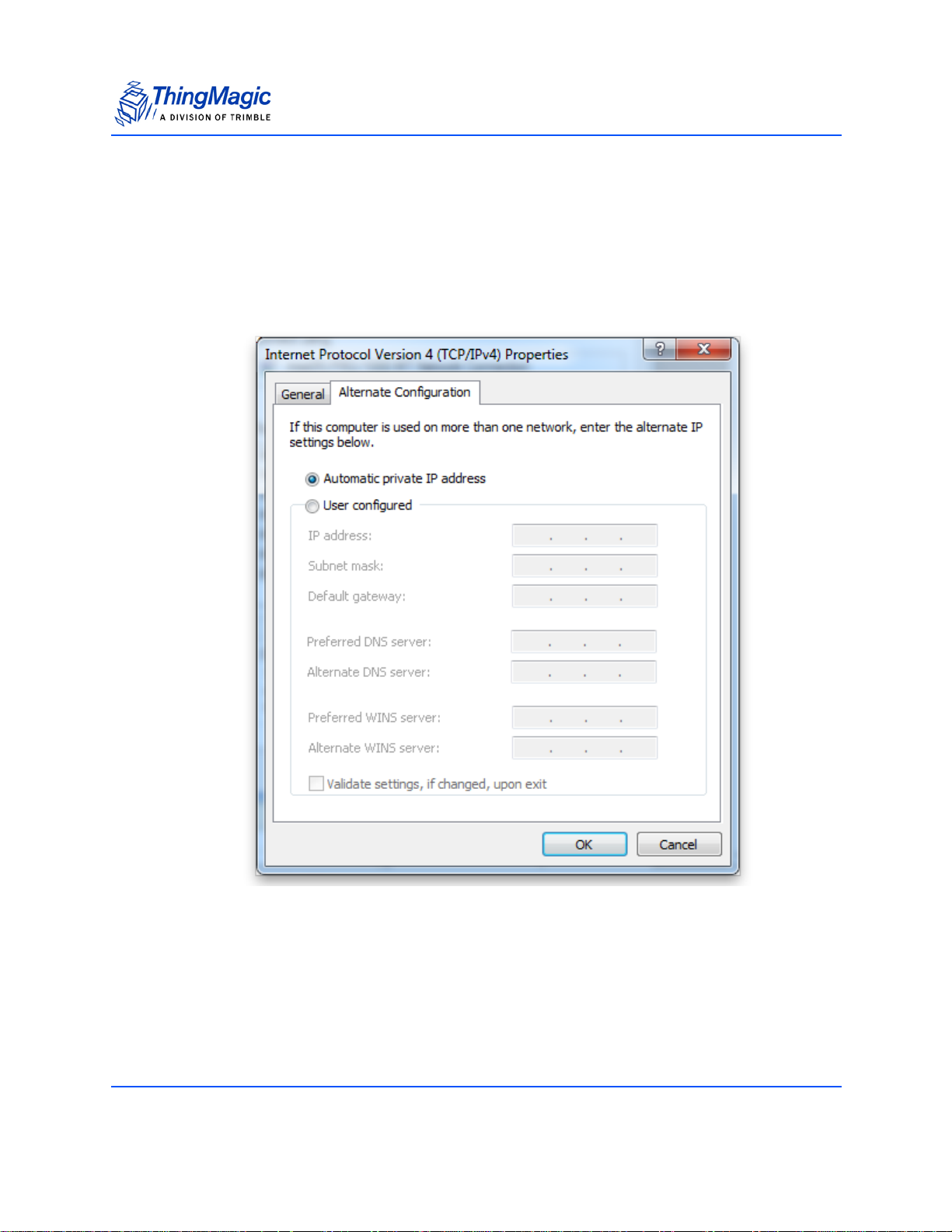
The Internet Protocol (TCP/IP) Properties window appears. The General tab
should have both “Obtain an IP Address automatically” and “Obtain DNS server
address automatically” selected. On the Alternate Configuration tab “Automatic
private IP address” should be selected, as shown in
Figure 6.
Figure 6: Internet Protocol TCP/IP Properties Window
8. Click OK to save and exit the window.
9. Click OK in the Local Area Connection Properties window.
M6 and Astra-EX User Guide 21

Setting Up the Reader
Note
Logging On to the Reader
You may use any Java-enabled web browser to log on to the Reader.
To log on to the Reader:
1. Launch your web browser and log on to the Reader by entering the Reader's
Automatic Hostname: M6-xxxxxx or Astra-EX-xxxxxx
2. Press Enter.
The Login dialog box appears.
3. Enter the following:
Default user name: “web”
Password: “radio” (all lower-case).
4. Click OK.
The Reader displays its browser-based interface. The initial page that appears
is the Status page, as shown in Figure 7.
in the address bar.
On some systems, especially when Communicating with the Reader using a Link-
local Address, the hostname must end in “.local” for the connection to succeed. i.e.
m6-21071f.local
M6 and Astra-EX User Guide 22
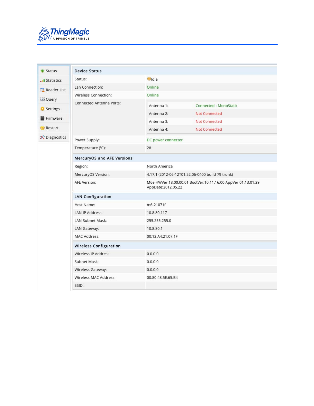
Figure 7: M6 and Astra-EX Status Page
Setting Up the Reader
M6 and Astra-EX User Guide 23

Setting Up the Reader
5. Check the Connected Antenna Ports fields. If the text is green, it indicates that
antenna is connected.
6. Do one of the following steps:
To connect the Reader to the network and log in remotely, see Networking the
Reader.
To start reading tags and controlling the Reader, see Controlling the Reader.
This section guides you through all the available Reader functions available
through the web interface, including how to read tags, change settings, load
firmware, and reboot the Reader into Safe Mode.
M6 and Astra-EX User Guide 24

Networking the Reader
Note
You can set up the M6 and Astra-EX Reader to use either manual IP addressing or
DHCP. By default, the Reader has automatic addressing enabled that boots up looking
for a DHCP server. If no DHCP server is found it will use a Link-local address.
DHCP can be used to automatically assign the Reader's IP address, subnet mask, default
gateway, NTP Server, DNS server, and hostname. During the initial boot sequence, if the
Reader does not get a DHCP-assigned IP address, a link-local address will be negotiated
with any connected device(s). However, the Reader will periodically check to see if a
DHCP server is available. See the Troubleshooting Table
IP address if using the Automatic Hostname: M6-xxxxxx or Astra-EX-xxxxxx
work.
Networking the Reader
for assistance determining the
doesnʼt
The following section explains how to set up your PC and Reader Using DHCP
section also explains how to manually configure the Reader without a DHCP server, how
to setup advanced Fallback Interface Options
ZeroConf protocol, Bonjour
TM
, for subnet Reader Discovery, without a DHCP server.
Setting Up the Network Hardware
Whether you use DHCP or static network addressing, make sure that the network is
connected before powering up the Reader. If the Reader does not automatically get the
address from a DHCP server, then, by default, a link-local address is used.
Before setting up your network:
Connect one end of an Ethernet cable to the Reader and the other end to an
Ethernet switch or hub.
Check that all antennas are securely connected, and then power-up the
Reader.
Connect your PC to the same network as that of the Reader.
. This
(wired and wireless) and how to use the
Some older 10baseT network hubs do not work properly with the Reader. If you
encounter connectivity problems, we recommend using nothing below 10/100baseT
hubs/switches.
M6 and Astra-EX User Guide 25

Networking the Reader
CAUTION!
!!
Using the Wireless Network
You can connect the M6 and Astra-EX Reader through the wireless network, only if the
WiFi SKU is purchased. In this configuration, the Ethernet cable connection is not used.
To connect the M6 and Astra-EX Reader to a wireless network:
1. Click on Settings in the Web Interface navigation menu to access the Settings
Page, as shown in Figure 8.
2. Select the Network Interface tab then the Wireless (802.11) radio button in the
All Interfaces section.
3. Enter the appropriate information into the Wireless Authentication Mode, Select
the Wireless SSID, and Wireless Key for the Wireless Interface fields.
4. Once the wireless settings are entered click the Test Wifi button. This will
temporarily bring down the active network interface and try to connect to the
wireless network as configured. Success or failure will be indicated and the
active interface re-established. If the test fails then there is a problem with the
configuration settings and they should not be saved.
Do not navigate away from the settings page or disconnect from the network during a wifi test.
5. If the test was successful click the Save Changes button at the bottom of the
page.
6. As soon as Save is clicked the new network settings will be applied. This may
cause a temporary disconnect from the reader and may require a new IP
address to be entered or wait until the DNS server is updated with the new IP
address.
M6 and Astra-EX User Guide 26

Networking the Reader
CAUTION!
!
!
Once the reader Network Interface is switched to wireless it will no longer be accessible on the wired interface by default. During initial configuration, prior to switching to wireless, it maybe useful to configure the
wired interface as a fallback as described in Fallback Interface Options. If the
wireless settings were not configured correctly and no fallback setup,
the reader will not be accessible over the network interfaces. In that
case the only methods of recovery is by Connecting to the USB Console Port or
Using Safe Mode.
M6 and Astra-EX User Guide 27

Figure 8: M6 and Astra-EX Settings Page
Networking the Reader
M6 and Astra-EX User Guide 28

Networking the Reader
Note
WARNING!
WARNING!
Using Power Over Ethernet (PoE)
Another way of powering up the M6 and Astra-EX Reader is to use a single Ethernet
cable that is connected to a Power over Ethernet (PoE) network. In this configuration a
power converter is not used.
To power up the M6 and Astra-EX Reader over a PoE network:
1. Connect one end of an Ethernet cable to the M6 and Astra-EX Reader
2. Connect the other end to a certified PoE port.
ThingMagic recommends using a PowerDsine 3006 or similar PoE Hub.
For operation in the EU region (applies to M6-EU and Astra-EX-EU hardware SKU
only) you must use the Ferrite Bead included with the M6 and Astra-EX Reader
when powering-up the Reader over a PoE network in order to meet ETSI regulatory
requirements. For proper operation, you must install the Ferrite Bead on the
Ethernet cable at the end closest to the M6 and Astra-EX Reader, as shown in
Figure 9. For proper installation, the Ferrite Bead should not be more than two
inches away from the connector
Figure 9: Ferrite Bead
When using PoE as a power source, the PoE must be supplied by a UL Listed
ITE device.
When using PoE as a power source the unit cannot be connected to an Ethernet
network with outside plant routing, including a campus environment. The
network must be contained within a single building.
M6 and Astra-EX User Guide 29

Using DHCP
M6 and Astra-EX Setup
DHCP addressing can be used with either physical interface. To enable DHCP:
1. Click on Settings in the Web Interface navigation menu to access the Modify
Settings Page, as shown in Figure 8.
2. Select Use DHCP? | Yes radio button under the settings section of the selected
Network Interface.
3. Click the Save Changes button at the bottom of the page.
PC Setup
To use DHCP to automatically assign your PC's IP address to insure common
configuration with the M6 and Astra-EX Reader:
1. Select Start from the Start bar, and then select Control Panel.
Networking the Reader
2. Double click the Network Connections icon.
3. Disable your PC's wireless connection, if one exists.
4. Double click the Local Area Connection icon.
The local area Connection Status window appears, as shown in Figure 4.
5. Click the Properties button.
The Local Area Connection Properties window appears, as shown in Figure 5.
6. Scroll down to the bottom of the list and select Internet Protocol (TCP/IP).
7. Click on the Properties button.
The Internet Protocol (TCP/IP) Properties window appears, as shown in
Figure 10.
M6 and Astra-EX User Guide 30

Networking the Reader
Figure 10: Internet Protocol (TCP/IP) Properties Window
8. Select the Obtain an IP address automatically button.
9. Click OK to save and exit the window.
10. Click OK, in the Local Area Connection Properties window.
11. Click OK, in the Local Area Connection Status window.
The PC may take few minutes to save the new network settings.
M6 and Astra-EX User Guide 31

Networking the Reader
Note
Note
Automatic Hostname: M6-xxxxxx or Astra-EX-xxxxxx
At startup, the Reader, by default, generates an 'automatic hostname' by appending the
last three bytes of its MAC address to its hostname, such as M6-210027.
Your network must have properly configured DNS servers or you must be
Communicating with the Reader using a Link-local Address if you wish to connect
to the Reader through its hostname. When using DHCP, the DHCP server
periodically adds the hostname to the DNS server's database.
On some systems, especially when Communicating with the Reader using a Link-
local Address, the hostname must end in “.local” for the connection to succeed. i.e.
m6-21071f.local
MAC Address
The Reader's MAC address is printed on a white label on the side of the Reader, as LAN:
#...#. You can also find the Reader's MAC address on the Status page.
The first six characters of the MAC address are ThingMagic's manufacturer's code. The
last six characters of the MAC address are specific to the Reader and are used for
automatic hostname addressing.
To log on to the Reader using the MAC address:
1. Obtain the Reader's MAC address, launch your web browser, and then log on to
the Reader by entering its automatic hostname in the address bar, such as http:/
/M6-xxxxxx (the last six characters of the Reader's MAC address).
2. Press Enter.
The Reader's Login dialog box appears.
3. Enter the following:
User name: web
Password: radio
4. Click OK.
The Reader displays the M6 and Astra-EX Status Page
5. Check the Connected Antenna Ports fields. If the text is green, that antenna is
connected.
.
M6 and Astra-EX User Guide 32

Fallback Interface Options
In addition to selecting the primary physical interface to Wired (Ethernet) or Wireless
(802.11, if option was purchased), the M6 and Astra-EX can be configured to fallback to
one of a variety of alternative network configurations in case of failures on the primary.
Each physical interface can be configured to fallback to the other physical interface or to a
different, static configuration on the same physical interface. See Figure 1 1 for a flowchart
showing the various fallback behaviors. See Network Settings: All Interfaces
following Network Settings tables for more details on the settings.
Fallback settings are configured using the Web Interface | Settings page, as show in
Figure 8. To enable the use of fallback select:
Use Fallback Interface = Yes
Once fallback is enabled the fallback interface can be selected using:
Fallback Network interface = Wired | Wireless
Networking the Reader
and the
Fallback to the Same Physical Interface
If the Fallback Network interface selected is the same as the Interface being configured,
for example
Network Settings: Ethernet Interface
– Fallback Network interface = Wired is selected
Then the Fallback IP Address, Fallback Netmask and Fallback Gateway must be
configured and when a fallback occurs those static settings will be used.
Fallback to the Other Physical Interface
If the Fallback Network interface selected is different than the Interface being configured,
for example
Network Settings: Ethernet Interface
– Fallback Network interface = Wireless is selected
Then the Fallback IP Address, Fallback Netmask and Fallback Gateway are not used.
Instead, if a fallback occurs the physical interface will switch to using the other interface
as if it were primary.
M6 and Astra-EX User Guide 33

Figure 11: Fallback Interface Flowchard
Networking the Reader
M6 and Astra-EX User Guide 34

Networking the Reader
CAUTION!
!
!
CAUTION!
!
!
Its is not advisable to configure both interfaces to fallback to the other
physical interface. If neither is able to connect it will continue to “ping
pong” back and forth between the two interfaces. One of the two should
always fallback to a known static configuration.
When setting up and testing the Wireless interface as the primary interface it is strongly advisable to configure it to fallback to the wired interface and the wired falling back to a static wired IP address. This will
make it easier to recover if the wireless configuration is not done correctly.
M6 and Astra-EX User Guide 35

Reader Discovery
Note
You can find the available Readers on the network by using the Multicast DNS (mDNS)
protocol (http://multicastdns.org/) and Reader Listing.
Using mDNS
To find Readers on a network, you can use any client or client API that allows discovery of
services using mDNS (a part of the Zero Configuration Network Standard). One common
client implementing the Zero Configuration Network Standard is called Bonjour
developed by Apple. Bonjour works on networks without a DHCP server and is included
in the Apply Safari web browser (it must be selected during the Safari install).
After you have installed Safari the Bonjour icon appears under Bookmarks | Collections
You can select the Bonjour tool to discover other Readers available on the network.
Each ThingMagic Reader in the Bonjour frame is referenced by the domain name
(ThingMagic) followed by the hostname (M6 or Astra-EX) and the last six
characters of the device's MAC address (such as 210027).
A device frame on the left side of the browser opens and lists the names of all
active Bonjour devices available.
Networking the Reader
,
TM
1. Double-click on the name of the Reader that you want to access.
The Login dialog box for that specific Reader appears.
2. Enter the following:
User name: web
Password: radio
3. Click OK.
The Reader displays the Status page of the selected Reader.
The list of Bonjour devices displayed on the screen is refreshed periodically so that new
Bonjour-enabled devices appear as they come online.
Reader Listing
The Reader Listing Page allows you to find Readers including ThingMagic M6, Astra-EX,
Astra, and Mercury5, that run on the network. It uses the same Multicast DNS(mDNS)
protocol used by the Bonjour.
M6 and Astra-EX User Guide 36

Networking the Reader
Note
Note
In the case of Reader Listing Page, no plugin is required and works in any browser. The
Reader Listing Page contains a list of the Readers found on the network and additional
information on each Reader including:
A link to the Readerʼs web interface
Readerʼs IP address
Firmware version it is running
Number of connected antennas
Status information
Identify Reader button.
To enable Reader Listing to discover Readers available on the network:
Click on the Reader List link in the navigation menu.
The M6 and Astra-EX Reader Listing Page appears, as shown in the Figure 12.
Identify Reader
In the last column of the list of readers found there is a button labelled IdentifyReader.
When clicked this will cause the corresponding readerʼs LED to flash between green and
red. This provides visual confirmation of the named reader.
M6 and Astra-EX readers must be using firmware version 4.17 or later to support
this functionality.
By default Identify Reader will not work with Windows Internet Explorer (IE). IE by
default blocks URLs with username and passwords. In order to compromise that
setting, Windows provides a Fix It solution which is provided here.
http://support.microsoft.com/kb/834489#FixItForMeAlways
This is a one time setup.
M6 and Astra-EX User Guide 37

Figure 12: M6 and Astra-EX Reader Listing Page
Networking the Reader
M6 and Astra-EX User Guide 38

Connecting to the USB Console Port
Connecting to the USB Console Port
M6 and Astra-EX supports communication over its USB Console port to enable you to:
Access the boot logs.
Access the console for emergency recovery into Safe Mode.
Before you connect to the USB Console port, ensure that you have:
A PC with a USB port.
A serial terminal program (such as HyperTerminal or Putty).
A USB cable (with USB Mini-B plug)
FTDI USB to Serial Drivers
Once the USB cable is connected you must determine the port name used by the host OS
to connect. On Windows it will be assigned a "COM#" and Macintosh, and other unix
based systems will see it as "/dev/tty.usbserial0" or simlar.
When you have completed setting up the serial port, you must set the following four
parameters to allow the terminal program to talk to the Reader:
– Data Rate: 115200
– Parity: None
– Data Bits: 8
– Stop Bits: 1
The procedure for connecting to a specific port is different for each terminal emulation
program. Check the documentation for your program for information on setting these
parameters.
Once you have set up the USB connection, reboot the Reader, and the boot logs begin to
display. If not, recheck the terminal program configuration and try again.
FTDI USB to Serial Drivers
The console port requires the host has FTDI USB to serial virtual COM port drivers
installed. Most OSes have them pre-installed but if not they can be found at
http://www.ftdichip.com/Drivers/VCP.htm.
Please follow the instructions in the installation guide appropriate for your operating
system.
M6 and Astra-EX User Guide 39

Using GPIO
The M6 and Astra-EX Reader includes a 15-pin D-Sub connector (also commonly
referred to as a VGA connector). This connector is used to support four opto-isolated
general purpose inputs and four opto-isolated general purpose outputs. The values of the
GPIO lines can be Get and Set using the MercuryAPI. See the respective guide for more
details on software control of these signals. For ease of testing the following parts
(included in M6 and Astra-EX devkit) can be used to provide a terminal block interface to
the GPIO pins:
– VGA male to male connector (for GPIO) [L-Com Part# DMB520M]
– VGA to terminal block (for GPIO) [L-Com Part# DGBH15FT]
Inputs
The four opto-isolated inputs support the following input levels:
Using GPIO
It is recommended that external devices guarantee a minimum pulse width of at least
100ms.
Outputs
The four opto-isolated outputs support power sourcing, up to +30V with current sink up to
200mA, through an external power supply connected between V-GPO and ISO-GND
(pins 5 and 6).
Using the MercuryAPI the output signals (see note under Connector Pinout
enumeration values) can be set as follows:
All outputs have an active pull down to ISO-GND.
V-low (Logic 0) = 0-0.8V
V-high (Logic 1) = 3-30V
5mA max current with 24V input
for
gpoSet(GPIO_#, 0) sets pin corresponding to GPIO enumeration to Vhigh through
10kohm pull up resistor to V-GPO.
gpoSet(GPIO_#, 1) sets pin corresponding to GPIO enumeration to Vlow through
effective short (through isolated FET switch) to ISO-GND.
M6 and Astra-EX User Guide 40

Note
For non-isolated applications connect grounds together (pin6 and 7) and V-GPO to
M6 and Astra-EX+5V (pins 1 and 5). With this configuration the reader provides the
+5V supply and can sink up to 200mA, total.
Connector Pinout
The following are the pin-outs of the 15-pin connector:
Using GPIO
Figure 13: DE15 GPIO Pinout
1. M6 and Astra-EX+5V - non-isolated power from M6 and Astra-EX
2. N/A
3. N/A
4. User Output 2 (GPIO_1)
5. V-GPO - Isolated source power for outputs
6. ISO-GND - Isolated ground for outputs
7. M6 and Astra-EX Ground - non-isolated ground
8. User Output 1 (GPIO_0)
9. User Output 2 (GPIO_1)
10. User Output 3 (GPIO_2)
11. User Output 4 (GPIO_5)
12. User Input 1 (GPIO_3)
13. User Input 2 (GPIO_4)
14. User Input 3 (GPIO_6)
15. User Input 4 (GPIO_7)
Note: The values in parentheses indicate the enumeration used by the MercuryAPI for each GPIO line.
M6 and Astra-EX User Guide 41

Using GPIO
Note: Note that Pin 9 is normally not populated on standard VGA cables. The M6 and Astra-EX
internally connects Pin 9 to Pin 4 to permit the use of such cables.
M6 and Astra-EX User Guide 42

Controlling the Reader
The Reader uses RFID (Radio Frequency Identification) technology to read and write data
stored on RFID Tag(s).
The M6 and Astra-EX Reader provides three levels of access to controlling read/write
operations of RFID tag(s):
Controlling the Reader
1. Using the Browser-Based Interface
A web browser controls high-level Reader operations through a Java Applet.
See Status Page
interface.
2. MercuryAPI
High-level APIs (Application Programming Interface) provide fine control over all
aspects of the Reader.
See the MercuryAPI Programmers Guide at http://rfid.thingmagic.com/devkit.
3. LLRP
EPCglobal ratified protocol used for communication between the M6 and AstraEX and a client application. The M6 and Astra-EX should be “drop-in
compatible” with systems supporting the standard LLRP protocol.
for information about how to access the browser-based
Using the Browser-Based Interface
The M6 and Astra-EX Reader browser-based interface communicates directly with the
RFID Reader. It includes several tools that enable you to monitor Reader performance,
change Reader settings, and upgrade Reader firmware.
You can run the browser-based interface from any PC on the network. Carefully configure
the PC with an IP address and subnet mask compatible with the current operational
settings of the Reader.
The Reader navigation menu provides access to the following pages:
Status Page- Displays the current operational settings.
Query Page- Allows the user to perform Anti-Collision RFID tag searches and to
specify the constraints used in the search.
Settings Page- Allows the user to modify Reader configuration and network
settings.
M6 and Astra-EX User Guide 43

Controlling the Reader
Note
Note
Firmware Upgrade Utility- Upgrades the tag Reader with new firmware images
provided by ThingMagic.
Restart Page- Allows the user to restart the Reader through a "warm boot."
Diagnostics Page- Provides the current operating settings and access to the
status logs of the Reader.
Statistics Page- Provides the statistics that are defined by the EPCglobal Reader
Management Standard v1.0.1
To start the browser-based interface:
1. Exit all Reader applications on the network.
Running another Reader application while using the browser-based interface may
cause a Reader error. If this happens, reboot the Reader or restart it using the
browser-based interface.
2. Start a Java-enabled web browser from any network-enabled PC.
3. Type the IP address of the Reader to which you want to communicate in the
address field of the browser. You can also use Reader Discovery
browse to it.
A log-in dialog appears.
4. Enter the following:
User name: "web"
Password: "radio" (all lower-case).
5. Click OK.
A navigation menu and the Status page appear in the browser, as shown in the
Figure 7.
methods to
Status Page
The M6 and Astra-EX Status Page, as shown in the Figure 7, indicates the connected
antennas, software version, and LAN configuration of the Reader.
Check to see that at least one antenna port is connected before performing any tag
query operations.
M6 and Astra-EX User Guide 44

Controlling the Reader
Note
Query Page
Use the M6 and Astra-EX Query Page to set up and run Anti-Collision Searches quickly,
and to obtain immediate feedback. This is useful for debugging as well as for verifying
performance after installation is completed.
If the Query page does not load and you do not see the Java logo, install the Java
Runtime Environment for your platform and restart your PC.
Use of the Query applet, or any Reader client application, requires port 5084 to be
open on the network. If the Query applet Connect fails to connect it is likely either
another client already has an open connection or port 5084 is being blocked by a
firewall.
The basic steps to connect, read, modify the read behavior and display options are
defined in the following sections:
Read Tags
Query Results
Query Settings
In addition to modifying the query behavior using the Query Settings, the performance of
the reader can be optimized for a particular usecase by making changes to the Gen2
Protocol Settings.
Read Tags
To read tags under default performance and display options:
1. Click ʻConnectʼ to reader. A connection will not be successful if other clients are
connected to the reader.
Figure 14: Query Page - Connect
2. Position one or more tags, in front of one of the antennas connected to the
Reader.
3. Click ʻReadʼ.
M6 and Astra-EX User Guide 45

Controlling the Reader
Note
The Query will be run on all connected antennas (checked antennas) in the default
configuration. If Reader Power Settings
query on must be selected. The query can be run once or continuously.
4. Click ʻStop Readingʼ to end the search.
You must click Stop Reading and Disconnect before exiting. Otherwise, the Reader
will continue to transmit RF energy on its antennas and other clients maybe
blocked.
| Antenna Detection = Off then the antennas to
Query Results
As shown in Figure 15, the default displayed tag results shows the following columns of
data:
# - The order each tag was read.
EPC - The EPC ID of the tag, typically 96-bits of data shown in Hex.
ReadCount - The number of times the tag was read on [Antenna].
Antenna - The antenna on with the tag was read. If the same tag is read on more than
one antenna there will be a tag entry for each antenna on which the tag was read.
Protocol - The protocol of the tag.
Figure 15: Query Results
In addition to the above fields, the following fields can be displayed by right-clicking on the
settings icon in the top-right corner of the display table, as shown in Figure 16.
RSSI - The receive signal strength of the tag response, in dBm.
Frequency - The frequency on which the tag was read, in kHz.
First Seen - The timestamp when the tag was first seen during this query.
Last Seen - The timestamp of the most recent reading during this query.
M6 and Astra-EX User Guide 46

Controlling the Reader
Phase - Average phase of tag response in degrees (0°-180°)
TagReadData - The data read when the Tag Data Settings | Read Data option is
selected. If the tag doesnʼt have the requested data “Read Data failed” will be returned.
Figure 16: Add Meta Data Columns
Query Settings
The default reading mode of continuous reading can be changed, along with other query
behavior and display options in the settings panel. To access the panel click the “Show
Settings” button once connected, as shown in Figure 17.
M6 and Astra-EX User Guide 47

Figure 17: Query Settings Panel
Controlling the Reader
Once clicked the settings panel will slide out and expose several groupings of settings:
Read Settings
These settings control the behavior of the Read button:
Read Once - Each click of Read causes a single query for the time specified.
Read Continuously - Clicking Read causes a continuous read to be run until Stop
Reading is clicked.
Optionally select/deselect protocols, antennas, use Fast Search (optimizes
performance for maximum re-reads of a few tags).
Tag Data Settings
This settings allows an additional block of data, up to 64 bytes, to be read from each tag
during the query.
M6 and Astra-EX User Guide 48

Controlling the Reader
Note
Memory Bank - The memory back from which to read.
Start Address - The word offset in memory to start reading from.
Words to read - The number of words to read, beginning at the start address.
Specify ʻ0ʼ to read the full contents of the memory bank, from Start Address on.
Up to 128 bytes.
If the address and/or words to read value specified exceeds the contents of the tag,
no data will be read.
Tag Display Options
Settings to optionally display various summary information, while querying, in a big
number format.
Copy will copy the tag data to the clipboard.
Monitor Results
Displays of summary information when query completes.
M6 and Astra-EX User Guide 49

Controlling the Reader
Note
Note
Settings Page
The M6 and Astra-EX Settings Page enables you to change network, performance and
security settings. The page is divided into four main sections:
Reader Power Settings
Gen2 Protocol Settings
Network Settings
Miscellaneous Settings
Changing these parameters changes the settings the Reader uses on startup. Although
boot options and network settings can be modified, be careful to use correct values or you
may not be able to connect to the Reader without restarting in Safe Mode.
All settings set through the WebUI | Settings pages are persistent, they are
retained across reboots and become the default settings of the reader for client
applications. The values shown on these pages do not necessarily reflect the active
settings of the Reader if configuration parameters are transiently changed through
the MercuryAPI or LLRP. All changes made through MercuryAPI or LLRP client
applications are transient.
Do not disconnect power until the save process is complete. Note that new RFID,
network and security settings take effect after saving. Boot-related options are
saved but DO NOT take effect until the Reader is restarted (see Restart Page
Therefore, to ensure that all new settings take effect, it is recommended that you
restart the Reader after saving the new settings and after reconfiguring.
).
Reader Power Settings
The Reader Power Settings are used to control the amount of RF Power transmitted by
the reader when active. The RF power directly relates to the range at which the reader
can “see” tags, the higher the power, the longer the range.
M6 and Astra-EX User Guide 50

Table 1: Reader Power Settings
Setting Description
RF Power Setting Controls the method used for setting power:
• Global - all antennas will use the same power setting, the value of RF Power.
• Per Antenna - power for each antenna must be set individually for each and
antenna and both read and write power settings, the value of Antenna # Read/
Write Power.
Controlling the Reader
Antenna # Read
Power (dBm)
Antenna # Write
Power (dBm)
Antenna Detection Controls whether the reader will automatically detect connected antenna and only
The power setting used for Read operations on antenna #. This setting is only
used when RF Power Setting is set to Per Antenna.
The power setting used for Write operations on antenna #. This setting is only
used when RF Power Setting is set to Per Antenna.
allow those ports to be used:
• On - Only ports with antennas that meet the Antenna Detection
requirements will be active.
• Off - All ports are available for use. The user MUST specify the spe-
cific antennas to transmit on and is responsible for ensuring transmits
do not occur on ports without connected antennas.
Gen2 Protocol Settings
The Gen2 Protocol Settings allow for optimization of the Reader's performance based on
real world usecase requirements. In addition, for advanced users, direct setting of low
level Gen2 protocol parameters are available using the Customize option of each section.
M6 and Astra-EX User Guide 51

Table 2: Gen2 Protocol Settings
Setting Description
Controlling the Reader
Tag Reader
Protocol Settings
Tag Population
Size Settings
Tag Repeat Rate
• Maximum tag read rate - Performance is optimized for maximizing the speed
of tag to/from reader communications, which results in more tags being read
faster. OR
• Maximum receive sensitivity - Performance is optimized for reading weaker,
harder to read tags.
Note: NOTE: Mostly applicable to using Battery Assisted Passive Tags. Most
Passive Tag applications are range limited by the power output from the
antenna, not the reader's ability to "hear" a tag's response.
• Customize - Set low level Gen2 parameters related to tag to reader
communication speed vs sensitivity. See the MercuryAPI Programmers Guide |
Performance Tuning section for more details on these settings.
• Automatically adjust settings as tag population changes - Reader
dynamically adjusts optimization setting depending on the tag population it
detects in the field.
• Adjust settings for an approximate population of X - If the tag population
size is relatively well known and consistent, performance can be increased by
optimizing for that size. In this case enter the approximate population size for
increased performance.
• Customize - Set low level Gen2 parameters related to tag population size. See
the MercuryAPI Programmers Guide | Performance Tuning section for more
details on these settings.
• Tags repeat as often as possible - Tags will re-respond to an on-going
inventory operation as quickly as possible.
• Tags wait ~0.5 seconds to repeat - Tags will sleep for their "flag persistence"
period, typically 0.5 to 2.0 seconds. This is preferred when trying to inventory
large populations of tags as it allows "weaker" tags a chance to respond.
• Customize - Set low level Gen2 parameters related to tag response rate and
session usage. See the MercuryAPI Programmers Guide | Performance
Tuning section for more details on these settings.
Network Settings
Static network settings are ignored when in DHCP mode, and DHCP-related settings are
ignored when in static IP mode. Please note that your network needs to have properly
configured DNS servers, to connect to the Reader through its hostname. Usually when
using DHCP, the DHCP server will add the hostname to the DNS server's database.
M6 and Astra-EX User Guide 52

Network Settings: All Interfaces
Table 3: Network Settings: All Interfaces
Setting Description
Network Interface Select between Wired (Ethernet) and Wireless (802.11).
Controlling the Reader
Automatic
Hostname
Hostname This field contains the name of the Reader.
NTP Server This field contains the address of any network time protocol server(s) (Optional).
Domain Name This field contains the network domain name.
Primary DNS
Server
Secondary DNS
Server
Turning on automatic hostname will append the last six numbers (3 bytes) of the
Readerʼs address to the text in the hostname field.
For example, given a hostname of M6 or Astra-EX and a MAC Address of 00:12:A4:
13:47:AC, the automatic hostname would be M6-1347ac or Astra-1347ac.
This field allows the M6 and Astra-EX Reader to resolve hostnames to IP
addresses.
This field allows the M6 and Astra-EX Reader to resolve hostnames to IP
addresses.
Network Settings: Ethernet Interfaces
Table 4: Network Settings: Ethernet Interface
Setting Description
Use DHCP? If set to Yes, the Reader will automatically look for its LAN IP, Netmask, and Gateway
addresses from a DHCP Server.
Use Fallback
Interface
Fallback Network
Interface
Vendor Class
Identifier
Use DHCP
Server- supplied
Host- name?
M6 and Astra-EX User Guide 53
If set to Yes, the specified Fallback Network Interface will be used in case of
failure on this interfaceʼs primary configuration.
If set to Wired then the static Fallback IP, Netmask and Gateway will be used
in case of failure of the primary configuration on this interface. If set to
Wireless the interface will switch to wireless in case of failure.
This radio button enables 96-bit tag support. To optimize the Reader, keep this
setting turned off unless it is needed.
If set to Yes, the manually supplied hostname (see Hostname) will be overridden by
the hostname supplied by the DHCP Server.

Controlling the Reader
LAN IP Address If “Use DHCP?” is set to Yes, the LAN IP, Netmask, and Gateway values will be
supplied by the DHCP Server. Default or manually entered addresses will be dimmed
out and bypassed. If “Use DHCP?” is set to No, you should manually enter the
LAN IP, Netmask and Gateway settings.
LAN Gateway This is the gateway IP address for the local network, typically the IP address of a
router.
LAN Netmask This is the subnet mask IP address used to determine to which TCP/IP subnet the
Reader belongs. Devices in the same subnet can be communicated with locally
without going through a router.
Fallback IP
Address
Fallback
Netmask
Fallback
Gateway
This network configuration will be used by the Reader if DHCP is enabled but
fails to acquire an IP address.
This network configuration will be used by the Reader if DHCP is enabled but
fails to acquire an IP address.
This network configuration will be used by the Reader if DHCP is enabled but
fails to acquire an IP address.
Network Settings: Wireless Interfaces
The wireless interfaces apply only when your reader supports Wi-Fi.
Table 5: Network Settings: Wireless Interface
Setting Description
Use DHCP? If set to Yes, the Reader will automatically look for its LAN IP, Netmask, and Gateway
addresses from a DHCP Server.
Use Fallback
Interface
Fallback Network
Interface
If set to Yes, the specified Fallback Network Interface will be used in case of
failure on this interfaceʼs primary configuration.
If set to Wireless then the static Fallback IP, Netmask and Gateway will be
used in case of failure of the primary configuration on this interface. If set to
Wired the interface will switch to wired in case of failure.
Vendor Class
Identifier
Use DHCP
Server- supplied
Host- name?
WLAN IP
Address
M6 and Astra-EX User Guide 54
This radio button enables 96-bit tag support. To optimize the Reader, keep this
setting turned off unless it is needed.
If set to Yes, the manually supplied hostname (see Hostname) will be overridden by
the hostname supplied by the DHCP Server.
If “Use DHCP?” is set to Yes, the LAN IP, Netmask, and Gateway values will be
supplied by the DHCP Server. Default or manually entered addresses will be dimmed
out and bypassed. If Use DHCP? is set to No, you should manually enter the LAN
IP, Netmask and Gateway settings.

Controlling the Reader
WLAN Gateway This is the gateway IP address for the local network, typically the IP address of a
router.
WLAN Netmask This is the subnet mask IP address used to determine to which TCP/IP subnet the
Reader belongs. Devices in the same subnet can be communicated with locally
without going through a router.
Wireless
Fallback IP
Address
Wireless
Fallback
Netmask
Wireless
Fallback
Gateway
Wireless
Authentication
Mode
Wireless SSID This field will contain the SSID of the wireless network to which the M6 and
Wireless Key This field will contain the Key for the wireless network to which the M6 and
This network configuration will be used by the Reader if DHCP is enabled but
fails to acquire an IP address.
This network configuration will be used by the Reader if DHCP is enabled but
fails to acquire an IP address.
This network configuration will be used by the Reader if DHCP is enabled but
fails to acquire an IP address.
Select WEP, WPAPSK, or WPA2PSK for authentication.
Astra-EX will connect.
Astra-EX will connect.
Miscellaneous Settings
Boot Option Settings
The boot option settings specify the location of downloadable firmware, configuration files
and their optional parameters, and the location of a syslog server to which all Reader
events may be sent.
Table 6: Boot Option Settings
Setting Description
Boot Config Options Optional parameters used when downloading a new configuration file to the
Reader.
-f : Force a downgrade if config file version is lower than that currently running on
the Reader.
-p : Preserve configuration settings under a wipe.
-w : Wipe flash memory and settings.
-a : Add the Readerʼs MAC address to the download filename.
M6 and Astra-EX User Guide 55

Controlling the Reader
Boot Config URI to the tm.conf file to be downloaded on startup. Specify local:default for local
tm.config file.
Boot Firmware
Options
Boot Firmware URL to the firmware file to be downloaded at startup.
Syslog Host Hostname for remote logging. All log levels in syslog are sent to this host.
Same as Boot Config options. Used when downloading new firmware to the
Reader.
Reader Identification Settings
The Reader identification settings show the user-defined identifier strings.
Table 7: Reader Identification Settings
Setting Description
Reader Description This is a user-defined identifier string to describe the Reader that gets
echoed back verbatim via the web interface, SNMP, or the API.
Reader Role This is a user-defined identifier string to describe the Readerʼs role in a
system that gets echoed back verbatim via the web interface, SNMP, or the
API.
Ant# Description This is a user-defined identifier string to describe the default Antenna # that
gets echoed back verbatim via the web interface, SNMP, or the API.
Security Settings
These settings control secure access to the Reader using a combination of SSH (Secure
Shell), HTTPS, and secure RQL calls.
Table 8: Security Settings
Setting Description
Secure Shell Only (disable telnet)
Secure Web Only (disable standard http)
SNMP Enabled Enables access to the reader statistics as defined by the EPC Global
MDNS enabled Enables reader discovery via Multicast DNS.
M6 and Astra-EX User Guide 56
If Yes, the telnet server is disabled, and Reader access can only be performed via
a secure shell (SSH).
If Yes, the Reader will only respond to requests using https URLs.
Reader MIB via Simple Network Management Protocol (SNMP).

Controlling the Reader
Note
Restart Page
The M6 and Astra-EX Restart Page enables you to activate reconfigured network Reader
settings or to recover from a Reader error.
To restart the Reader:
1. Click the Restart link on the navigation menu.
The Restart Reader page appears, as shown in Figure 18.
Figure 18: M6 and Astra-EX Restart Reader Page
2. Click the Restart System button.
3. Click OK.
The following message appears, as shown in Figure 19 and remains on the
screen until the Reader restarts.
Figure 19: Restarting Reader
It takes at least 60 seconds for the Reader to boot up. During this time the Power/
Heartbeat LED is solid amber. When the LED is solid green, the boot process is
complete.
M6 and Astra-EX User Guide 57

Controlling the Reader
Diagnostics Page
The Diagnostics page expands on information found on the Status Page, including the
current settings of the Reader, comprehensive version information, and the current status
of network interfaces.
M6 and Astra-EX User Guide 58

Controlling the Reader
Statistics Page
The Statistics Page displays the M6 and Astra-EX Reader statistics. These statistics are
defined by the EPCglobal Reader Management Standard v1.0.1, specifically, the
statistics defined in sections 5.5 AntennaReadPoint and 5.6 Source Object. These sames
statistics are available through the SNMP interface.
More information on these statistics can be found at the following URL:
http://www.epcglobalinc.org/standards/rm/rm_1_0_1-standard-20070531.pdf
Firmware Upgrade Utility
M6 and Astra-EX provides the Firmware Upgrade Utility for updating the firmware.
1. Click the Firmware link on the navigation menu.
The Firmware Update page appears, as shown in Figure 20.
Figure 20: M6 and Astra-EX Firmware Update Page
2. Do one of the following:
In the File upload field, enter the complete URL network pathname of the
firmware file.
Click Browse... to locate the firmware file.
M6 and Astra-EX User Guide 59

Controlling the Reader
Note
CAUTION!
!
!
CAUTION!
!!
If you select the "Erase contents before
installing" check box, you will erase all
user-installed programs or files residing on
the reader. DO NOT select this option if you
wish to preserve any user programs residing on the reader.
If you select the "Revert to default settings"
check box, you will erase any changes
made to the reader's configuration settings
and revert to factory default settings. If you
select this option, the reader's current configuration settings will be erased. DO NOT
select this option if you wish to preserve
the reader's current configuration settings.
3. Click the Update button to download the new firmware to the reader.
The status frame at the bottom of the page displays the progress of the update.
4. Restart the reader to activate the new firmware.
The old firmware remains active until the Reader is restarted.
If for any reason a firmware update fails, the device may restart in Safe Mode.
M6 and Astra-EX User Guide 60

Using Safe Mode
Note
There are two reasons to enter Safe Mode:
To perform a firmware update for repairing a corrupted filesystem.
To change settings that prevent the Reader from operating normally.
Both of these tasks can be performed through the web interface.
Safe Mode is used to recover from errors that prevent the Reader from operating in
normal mode. In Safe Mode the Reader is configured to try DHCP and fallback to a linklocal address (see Communicating with the Reader using a Link-local Address
When in Safe Mode the browser-based interface pages navigation menu will display
“Safe Mode” at the top and the Status page will indicate it is “Unable to communicate with
the MercuryOS server”. In this mode the Reader is still functional though it cannot read or
write tags. The web server, telnet server, and SSH (Secure Shell) server run in Safe
Mode, however none of the RFID features are activated.
Using Safe Mode
).
In most cases, after starting in Safe Mode, the Reader will need to be reconfigured for
operation with the Reader application, after starting in Safe Mode. To communicate with
the Reader in Safe Mode, your PC must be configured for DHCP (and automatic private
IP addressing on Windows). You can then reconfigure the desired settings through the
web interface. After you have completed the maintenance, restart the Reader to activate
the changes.
Force M6 and Astra-EX to boot in safe mode
The M6 and Astra-EX Reader can be forced to boot into Safe Mode in one of two ways:
Physically pressing the Reset Button:
1. With the reader running (green LED is solid), use a non-conductive object to
hold down the recessed reset button for 4 seconds.
2. The green LED should turn solid Amber as soon as the button its ready to boot
and the button can be released. It should take approximately 30 seconds to boot
into Safe Mode.
3. Once the maintenance has been performed, restart the reader to activate the
changes.
M6 and Astra-EX User Guide 61

Using Safe Mode
Command line interface (through console port or telnet/ssh):
1. Connect to the Readers serial port
(See Connecting to the USB Console Port
Enter the following to log into the console
Default UserID: root
Password: secure
2. Type the command: touch /tm/etc/safe-boot
3. Click the Enter button.
4. Type the command: reboot
5. Click the Enter button.
Reader reboots.
In both methods the M6 and Astra-EX will now boot into Safe Mode and you can connect
to it using the steps defined in Connecting Your PC to the Reader
.)
.
M6 and Astra-EX User Guide 62

Advanced Reader Functionality
Protocol Support
Using the MercuryAPI ReadPlan classes the M6 and Astra-EX can be configured to
perform various Read operations. The following describes protocol specific configuration
options supported on the M6 and Astra-EX. See the MercuryAPI Programmers Guide and
language specific reference guides for details on supported Gen2 command functionality.
ISO 18000-6C (Gen2)
Protocol Configuration Options
The M6 and Astra-EX supports multiple ISO-18000-6C profiles including the ability to
specify the Link Frequency, encoding schemes, Tari value and modulation scheme. The
protocol options are set in the MercuryAPI Reader Configuration Parameters (/reader/
gen2/*). The following table shows the supported combinations:
Advanced Reader Functionality
Backscatter
Link Frequency
(kHz)
250 Miller (M=8) 12.5 PR-ASK
250 Miller (M=4) 12.5 PR-ASK
250 Miller (M=2) 12.5 PR-ASK
250 FM0 12.5 PR-ASK
250 Miller (M=8) 25 PR-ASK
250 Miller (M=4) 25 PR-ASK
250 Miller (M=2) 25 PR-ASK
250 FM0 25 PR-ASK
250 Miller (M=8) 25 PR-ASK
640 FM0 6.25 PR-ASK
ISO-18000-6C Protocol Options
Encoding
Tari
(usec)
Modulation
Scheme
M6 and Astra-EX User Guide 63

Advanced Reader Functionality
ISO 18000-6B
Protocol Configuration Options
The M6 and Astra-EX, with appropriate license purchase, supports multiple ISO-180006B profiles including the ability to specify the Return Link Frequency, encoding, Forward
Link Rate and modulation scheme. The protocol options are set in the MercuryAPI
Reader Configuration Parameters (/reader/iso18000-6b/*). The following table shows the
supported combinations:
ISO-18000-6B Protocol Options
Return Link
Freq (kHz)
40 FM0 10 Manchester
40 FM0 10 Manchester
160 FM0 40 Manchester
160 FM0 40 Manchester
Return
Encoding
Forward Link
Freq (kHz)
Forward
Encoding
Tag Read Meta Data
When tags are being inventoried by the M6 and Astra-EX, in addition to the tag EPC ID
resulting from inventory operation each TagReadData (see MercuryAPI for code details)
contains meta data about how, where and when the tag was read. The specific meta data
available for each tag read is as follows:
Tag Read Meta Data
Meta Data Field Description
Antenna ID The antenna on with the tag was read. If the same tag is read
on more than one antenna there will be a tag object returned
for each antenna on which the tag was read.
Read Count The number of times the tag was read on [Antenna ID].
Timestamp The time the tag was read. For accurate time an NTP server
should be configured.
M6 and Astra-EX User Guide 64

Advanced Reader Functionality
Tag Read Meta Data
Meta Data Field Description
Tag Data When reading if an embedded TagOp is specified for a Read-
Plan the TagReadData can contain up to 128 bytes of data
returned for each tag.
Note: Tags with the same TagID but different Tag Data
can be considered unique and each get a Tag
Buffer entry if set in the reader configuration
parameter /reader/tagReadData/
uniqueByData. By default it is not.
Frequency The frequency on which the tag was read
Tag Phase
LQI/RSSI The receive signal strength of the tag response in dBm.
Average phase of tag response in degrees (0
°-180°)
M6 and Astra-EX User Guide 65

Reader RF Power
Note
WARNING!
During initial installation, the reader must be properly configured to use the correct RF
power to comply with FCC or other regional regulations. DO NOT increase the power
beyond this level.
The M6 and Astra-EX supports separate read and write power level which are command
adjustable via the MercuryAPI. Power levels must be between:
– Minimum RF Power = +5 dBm
– Maximum RF Power = +31.5 dBm (+0.0/- 0.5 dB accuracy above +15 dBm)
The maximum RF Power setting for the Astra-EX integrated antenna is 30dBm.
Operation using an RF Power setting above 30 dBm requires a
professional installer.
Reader RF Power
Power Settings for Authorized Antennas and Cables
This device has been designed to operate with the antennas listed in Authorized
Antennas list using the cables in the Authorized Cables list. For any combination of
antenna and cable the maximum RF power is determined from antenna gain (Max Linear
Gain value from antenna list) and antenna cable loss (Insertion Loss value from cable list)
using the formula:
Pmax = 36 dBm - Antenna Gain + Cable Loss
For example, for the Laird S8658WPL and the ThingMagic CBL-P6 6ft cable the following
calculation can be performed:
Max linear antenna gain = 6 dBiL
Minimum cable insertion loss = 0.8 dB
Pmax = 36 - 6 + 0.8 = 30.8 dBm
The maximum RF power that may be set using this configuration is 30.8 dBm (see
Warning above).
For more information about setting the RF power, refer to Setting the Reader RF Power
.
M6 and Astra-EX User Guide 66

Reader RF Power
Note
Be sure to read Compliance and IP Notices to maintain compliance with FCC or
other applicable regional regulations.
M6 and Astra-EX User Guide 67

Setting the Reader RF Power
Note
To set the Reader RF power:
1. Log on to the Reader using your browser.
The M6 and Astra-EX Status Page
2. Click on the Settings tab.
The first field on the Settings page is RF Power. Its factory default value is 30
dBm.
3. Enter the maximum setting based on your cable type, length, and antenna type.
Reader RF Power
appears, as shown in the Figure 7.
4. Scroll down to the bottom of the M6 and Astra-EX Settings Page
changes button.
The Settings Page will reload automatically after the settings have been saved.
If the Status page does not appear after a minute, manually recycle the power on
the Reader. After repowering, load the Settings Page again and check the new
maximum RF power setting.
, and click Save
M6 and Astra-EX User Guide 68

Mounting the Reader
CAUTION!
!!
Mounting the Reader
See Appendix B: M6 and Astra-EX Dimensions for mounting hole locations and
dimensions.
If there is any chance of dust or water exposure, the Astra-EX should be
mounted with the Ethernet, USB, Console, Power and GPIO ports facing
down to prevent ingress.
M6
When mounting the M6 reader it is recommended to use four #10 x ? in. min. screws or
M5 x 20 mm screws, with washers min. ? in. in diameter. Nylon plastic expansion wall
anchors shall be suitable for the screw size. The mounting surface should be minimum ?
in. drywall. If mounting to the ceiling use nylon hollow wall anchors suitable for the screw
size and application. As an alternative, # 10 x 1-1/2 in. screws and washers may be used
if mounting directly to a wall stud.
Follow these steps to mount the reader on a ceiling or wall:
1. Hold the reader in its mounting location and mark the position of the four
2. Drill holes for the screws and install wall or ceiling anchors if required. For ceiling
3. Hold reader over holes and insert the screws and tighten until almost flush with
4. Tighten the screws.
Astra-EX
When mounting the Astra-EX Reader it is recommend to use an NRTL approved VESA
100 mount, following the standard mounting procedure of the VESA mount referencing
the Astra mounting hole locations as shown in Figure 22.
Alternatively you can use the centered Tripod mounting hole for 1/4"- 20 screws. This is
for use with tripods shorter than one meter.
mounting screws.
mount, use only anchors specifically designed for ceilings.
the wall.
M6 and Astra-EX User Guide 69

Variables Affecting Performance
WARNING!
Reader performance may be affected by the following variables, depending on the site
where your Reader is being deployed:
Environmental
Tag Considerations
Multiple Readers
Environmental
Reader performance may be affected by the following environmental conditions:
Metal surfaces such as desks, filing cabinets, bookshelves, and wastebaskets
may enhance or degrade Reader performance.
Antennas should be mounted far away from metal surfaces that may adversely
affect the system performance.
Mounting the Reader
Devices that operate at 900 MHz, such as cordless phones and wireless LANs,
can degrade Reader performance. The Reader may also adversely affect the
performance of these 900 MHz devices.
Moving machinery can interfere the Reader performance. Test Reader
performance with moving machinery turned off.
Fluorescent lighting fixtures are a source of strong electromagnetic interference
and if possible should be replaced. If fluorescent lights cannot be replaced, then
keep the Reader cables and antennas away from them.
Coaxial cables leading from the Reader to antennas can be a strong source of
electromagnetic radiation. These cables should be laid flat and not coiled up.
The M6 and Astra-EX antenna ports may be susceptible to damage from
Electrostatic Discharge (ESD). Equipment failure can result if the antenna or
communication ports are subjected to ESD. Standard ESD precautions should
be taken during installation to avoid static discharge when handling or making
connections to the M6 and Astra-EX reader antenna or communication ports.
Environmental analysis should also be performed to ensure static is not building
up on and around the antennas, possibly causing discharges during operation.
M6 and Astra-EX User Guide 70

Tag Considerations
Note
There are several variables associated with tags that can affect Reader performance:
Application Surface: Some materials, including metal and moisture, interfere with
tag performance. Tags applied to items made from or containing these materials
may not perform as expected.
Tag Orientation: Reader performance is affected by the orientation of the tag in
the antenna field. The ThingMagic antenna is circularly polarized, so it reads
face-to but not edge-to.
Tag Model: Many tag models are available. Each model has its own
performance characteristics.
Multiple Readers
The Reader adversely affect performance of 900 MHz devices. These devices also may
degrade performance of the Reader.
Mounting the Reader
Antennas on other Readers operating in close proximity may interfere with one
another, thus degrading performance of the Readers.
Interference from other antennas may be eliminated or reduced by using either
one or both of the following strategies:
Affected antennas may be synchronized by a separate user application using
a time-multiplexing strategy.
Antenna power can be reduced by reconfiguring the RF Transmit Power
setting for the Reader.
Performance tests conducted under typical operating conditions at your site are
recommended to help you optimize system performance.
M6 and Astra-EX User Guide 71

M6 Specifications
Note
M6 Specifications
The following are the specifications for the M6 Reader.
UHF RFID Antenna Interface
Interface: Four RP-TNC Connectors
RF Power Output: Separate read and write levels, adjustable from 5 dBm to 31.5 dBm*
(1.4W) from 5 dBm to 31.5 dBm* (1.4W)
Frequency: Hop table with up to 62 entries, configurable in 50KHz steps, accommodating
the following ranges (hardware dependant):
– 902-928 MHz (FCC; NA, SA)
– 865.6-867.6 MHz (ETSI; EU)
– 865-867 MHz (MCIT; India)
– 917-920 MHz (KCC; KR)
Note: 1 - The first frequency channel (917,300kHz) of the KR2 region will be derated to +22dBm to meet
the new Korea regulatory requirements. All other channels operate up to +30dBm. In the worst case
scenario, each time the derated channel is used it will stay on that channel for 400ms. The fastest it
will move to the next channel, in the case where no tags are found using that frequency , it will move
to the next channel after 10 empty query rounds, approximately 120ms.
1
Power
Power over Ethernet: PoE 802.3af in both modes A and B (Supports 100m cable) Will
supply 2.5 W to either USB external device or internal WiFi adapter
Optional External DC Power: 10- 30 VDC supply voltage. Maximum DC power: 15 W
If a DC Power supply is used it must meet the following criteria:
- Be UL Listed
- Meet the above operating specs
- The output must comply with SELV and LPS characteristics
- Have a maximum operating ambient temperature that meets or exceeds the
intended M6 operating temperatures as covered under the UL Listing of the power
supply.
M6 and Astra-EX User Guide 72

Environmental
Note
Operating Temperature: -20°C to +50°C
If an external DC power supply with a lower operating ambient temperature, as
covered under the UL Listing of the power supply, is used then the operating
ambient temperature of the M6 would be reduced accordingly.
Storage Temperature: -40°C to +85°C
Physical Dimensions
19 cm L x 17.8 cm W x 3.4 cm H
(7.5 in L x 7.0 in W x 1.3 in H)
2 lbs (0.9kg)
M6 Specifications
Supported UHF Tag Protocols
EPC Class 1 GEN2 (ISO 18000-6C) with DRM
ISO 18000-6B (Optional)
IP-X: EM 412x (Optional)
Data/Control/Wireless Interfaces
Connectors:
– RJ45 (10/100 Base-T Ethernet)
– USB Type B (console port)
– USB Type A (accessory port)
– HD15 (GPIO interface)
– 2.5 mm screw-lock barrel (DC power)
– Female SMA (optional WiFi antenna)
Wireless:
– Internal 802.11 b/g (optional)
M6 and Astra-EX User Guide 73

– WEP 40-bit and 104-bit keys
– WPA & WPA2 with TKIP and AES algorithms with pre-shared keys or EAP-
– USB type A interface permits future support for external wireless
Indicators, switches, and GPIOs:
– 1 two-color LED status indicator
– reset switch
– Isolated GPIOs: 4 Inputs & 4 Outputs plus +5 VDC and ground references
Performance
Over 400 tags/second
Over 30 ft (9m) read distance with 6dBi antenna (36 dBm EIRP)
M6 Specifications
TLS
technologies.
Regulatory & Safety
FCC 47 CFR Ch. 1 Part 15
Industrie Canada RSS-21 0
ETSI EN 302 208 V1.1.1 and V1.2.1 (with corresponding M6-EU hardware)
ROHS Compliant, UL Listed
User Memory
12MB Flash
64MB RAM
M6 and Astra-EX User Guide 74

Astra-EX Specifications
Note
Astra-EX Specifications
The following are the specifications for the Astra-EX Reader.
UHF RFID Antenna Interface
Interface: One RP-TNC Connectors
RF Power Output: Separate read and write levels, adjustable from 5 dBm to 31.5 dBm*
(1.4W) from 5 dBm to 31.5 dBm* (1.4W)
Frequency: Hop table with up to 62 entries, configurable in 50KHz steps, accommodating
the following ranges (hardware dependant):
– 902-928 MHz (FCC; NA, SA)
– 865.6-867.6 MHz (ETSI; EU)
– 865-867 MHz (MCIT; India)
– 917-920 MHz (KCC; KR)
Note: 1 - The first frequency channel (917,300kHz) of the KR2 region will be derated to +22dBm to meet
the new Korea regulatory requirements. All other channels operate up to +30dBm. In the worst case
scenario, each time the derated channel is used it will stay on that channel for 400ms. The fastest it
will move to the next channel, in the case where no tags are found using that frequency , it will move
to the next channel after 10 empty query rounds, approximately 120ms.
1
Power
Power over Ethernet: PoE 802.3af in both modes A and B (Supports 100m cable) Will
supply 2.5 W to either USB external device or internal WiFi adapter
Optional External DC Power: 10- 30 VDC supply voltage. Maximum DC power: 15 W
If a DC Power supply is used it must meet the following criteria:
- Be UL Listed
- Meet the above operating specs
- The output must comply with SELV and LPS characteristics
- Have a maximum operating ambient temperature that meets or exceeds the
intended Astra-EX operating temperatures as covered under the UL Listing of the
power supply.
M6 and Astra-EX User Guide 75

Environmental
Note
Operating Temperature: -20°C to +50°C
If an external DC power supply with a lower operating ambient temperature, as
covered under the UL Listing of the power supply, is used then the operating
ambient temperature of the Astra-EX would be reduced accordingly.
Storage Temperature: -40°C to +85°C
Physical Dimensions
25.9 cm L x 25.9 cm W x 7.72 cm H
(10.2 in L x 10.2 in W x 3.0 in H)
4 lbs (1.8kg)
Astra-EX Specifications
Supported UHF Tag Protocols
EPC Class 1 GEN2 (ISO 18000-6C) with DRM
ISO 18000-6B (Optional)
IP-X: EM 412x (Optional)
Data/Control/Wireless Interfaces
Connectors:
– RJ45 (10/100 Base-T Ethernet)
– USB Type B (console port)
– USB Type A (accessory port)
– HD15 (GPIO interface)
– 2.5 mm screw-lock barrel (DC power)
– Female SMA (optional WiFi antenna)
Wireless:
– Internal 802.11 b/g (optional)
M6 and Astra-EX User Guide 76

– WEP 40-bit and 104-bit keys
– WPA & WPA2 with TKIP and AES algorithms with pre-shared keys or EAP-
– USB type A interface permits future support for external wireless
Indicators, switches, and GPIOs:
– 1 two-color LED status indicator
– reset switch
– Isolated GPIOs: 4 Inputs & 4 Outputs plus +5 VDC and ground references
Performance
Over 400 tags/second
Over 30 ft (9m) read distance with 6dBi antenna (36 dBm EIRP)
Astra-EX Specifications
TLS
technologies.
Regulatory & Safety
FCC 47 CFR Ch. 1 Part 15
Industrie Canada RSS-21 0
ETSI EN 302 208 V1.1.1 and V1.2.1 (with corresponding Astra-EX-EU
hardware)
ROHS Compliant, UL Listed
User Memory
12MB Flash
64MB RAM
M6 and Astra-EX User Guide 77

Compliance and IP Notices
Regulatory Compliance
EMC FCC 47 CFR, Part 15
Industrie Canada RSS-210
Federal Communication Commission Interference Statement
This equipment has been tested and found to comply with the limits for a Class B
digital device, pursuant to Part 15 of the FCC Rules. These limits are designed to
provide reasonable protection against harmful interference in a residential installation.
This equipment generates uses and can radiate radio frequency energy and, if not
installed and used in accordance with the instructions, may cause harmful interference to
radio communications. However, there is no guarantee that interference will not occur in a
particular installation. If this equipment does cause harmful interference to radio or
television reception, which can be determined by turning the equipment off and on, the
user is encouraged to try to correct the interference by one of the following measures:
Compliance and IP Notices
Reorient or relocate the receiving antenna.
Increase the separation between the equipment and receiver.
Connect the equipment into an outlet on a circuit different from that to which the
receiver is connected.
Consult the dealer or an experienced radio/TV technician for help.
This device complies with Part 15 of the FCC Rules. Operation is subject to the following
two conditions: (1) This device may not cause harmful interference, and (2) this device
must accept any interference received, including interference that may cause undesired
operation.
FCC Caution: Any changes or modifications not expressly approved by the party
responsible for compliance could void the user's authority to operate this equipment.
Industry Canada
Under Industry Canada regulations, this radio transmitter may only operate using an
antenna of a type and maximum (or lesser) gain approved for the transmitter by Industry
Canada. To reduce potential radio interference to other users, the antenna type and its
M6 and Astra-EX User Guide 78

Compliance and IP Notices
gain should be so chosen that the equivalent isotropically radiated power (e.i.r.p.) is not
more than that necessary for successful communication.
This radio transmitter (identify the device by certification number, or model number if
Category II) has been approved by Industry Canada to operate with the antenna types
listed in Authorized Antennas
permissible gain and required antenna impedance for each antenna type indicated.
Antenna types not included in this list, having a gain greater than the maximum gain
indicated for that type, are strictly prohibited for use with this device
Operation is subject to the following two conditions: (1) this device may not cause
interference, and (2) this device must accept any interference, including interference that
may cause undesired operation of the device.
To reduce potential radio interference to other users, the antenna type and its gain should
be so chosen that the equivalent isotropically radiated power (e.i.r.p.) is not more than
that permitted for successful communication.
To comply with IC RF exposure limits for general population/uncontrolled exposure, the
antenna(s) used for this transmitter must be installed to provide a separation distance of
at least 25 cm from all persons and must not be collocated or operating in conjunction
with any other antenna or transmitter.
and Authorized Cables tables with the maximum
Industrie Canada
Conformément à la réglementation d'Industrie Canada, le présent émetteur radio peut
fonctionner avec une antenne d'un type et d'un gain maximal (ou inférieur) approuvé pour
l'émetteur par Industrie Canada. Dans le but de réduire les risques de brouillage
radioélectrique à l'intention des autres utilisateurs, il faut choisir le type d'antenne et son
gain de sorte que la puissance isotrope rayonnée équivalente (p.i.r.e.) ne dépasse pas
l'intensité nécessaire à l'établissement d'une communication satisfaisante.
Le présent émetteur radio (identifier le dispositif par son numéro de certification ou son
numéro de modèle s'il fait partie du matériel de catégorie I) a été approuvé par Industrie
Canada pour fonctionner avec les types d'antenne énumérés ci-dessous et ayant un gain
admissible maximal et l'impédance requise pour chaque type d'antenne. Les types
d'antenne non inclus dans cette liste, ou dont le gain est supérieur au gain maximal
indiqué, sont strictement interdits pour l'exploitation de l'émetteur
Le fonctionnement de lʼ appareil est soumis aux deux conditions suivantes:
1. Cet appareil ne doit pas perturber les communications radio, et
M6 and Astra-EX User Guide 79

Compliance and IP Notices
WARNING!
2. cet appareil doit supporter toute perturbation, y compris les perturbations qui
pourraient provoquer son dysfonctionnement.
Pour réduire le risque d'interférence aux autres utilisateurs, le type d'antenne et son gain
doivent être choisis de façon que la puissance isotrope rayonnée équivalente (PIRE) ne
dépasse pas celle nécessaire pour une communication réussie.
Au but de conformer aux limites d'exposition RF pour la population générale (exposition
non-contrôlée), les antennes utilisés doivent être installés à une distance d'au moins 25
cm de toute personne et ne doivent pas être installé en proximité ou utilisé en conjonction
avec un autre antenne ou transmetteur.
Operation of the M6 and Astra-EX at RF power above 30dBm requires
professional installation to correctly set the TX power for the RF cable
and antenna selected.
M6 and Astra-EX User Guide 80

Appendix A: M6 and Astra-EX Antenna and Ca-
Note
ble Information
Appendix A: M6 and Astra-EX Antenna and Cable Information
Authorized Antennas
To comply with FCC requirements for RF exposure safety, a separation distance of at
least 25 cm (8.7 inches) must be maintained between the radiating elements of the
antenna and nearby people. You must also provide strain relief for all Reader
connections.
The only antennas authorized by the FCC for use with the M6 and Astra-EX Reader are
listed in the table below. Detailed information on each antenna is available from their
respective manufacturers. Antennas not included in this list or having a gain greater than
6dBiLare strictly prohibited for use with this device. The required antenna impedance is
50 ohms
Table 9: Authorized Antennas
Manufacturer Type
Laird Patch S9025P 4.3
Laird Patch S8658WPL 6.0
Laird Patch DCE8658WPR 6.0 dBiL
Laird Patch PEL90206 4.7 dBiL
Laird Patch S9026X 4.5 dBiL
MTI Patch MT-262013 6.0 dBiL
MTI Patch MT-242043 6.0 dBiL
MTI Patch MT-242042 4.1 dBiL
MTI Patch MT-241026 0.2 dBiL
Poynting Patch A-PATCH-0025 5 dBiL
Mobile Mark Patch PN8-915 6.0 dBiL
Mobile Mark Patch PN7-915 4.5 dBiL
Mobile Mark Patch PN6-915 4.0 dBiL
IMPORTANT: No other antennas may be used with the M6 and Astra-EX Reader
without violating FCC regulations. It is the responsibility of the user to comply with
this requirement.
Manufacturer Part
Number
Max. Linear
Gain (dBiL)
M6 and Astra-EX User Guide 81

ble Information
Authorized Cables
The following table contains the cable loss values for authorized shielded coaxial cables
provided by ThingMagic
Appendix A: M6 and Astra-EX Antenna and Ca-
Cable Description
6' RTNC to RTNC Cable CBL-P6 0.8 dB
12' RTNC to RTNC Cable CBL-P12 1.5 dB
20' RTNC to RTNC Cable CBL-P20 2.4 dB
20' RTNC to RTNC Plenum
Cable
25' RTNC to RTNC Cable CBL-P25 3.0 dB
ThingMagic Part
Number
CBL-P20-PL 2.4 dB
Insertion Loss
M6 and Astra-EX User Guide 82

Appendix B: M6 and Astra-EX Dimensions
Appendix B: M6 and Astra-EX Dimensions
M6 Dimensions
Astra-EX Dimensions
Figure 21: M6 Dimensions
M6 and Astra-EX User Guide 83

Appendix B: M6 and Astra-EX Dimensions
Figure 22: Astra-EX Dimensions
M6 and Astra-EX User Guide 84

Appendix C: Advanced Administration
Note
Appendix C: Advanced Administration
Changing the Web Interface uid/passwd
This steps below describe how to add/change the User/Password for the Web Interface.
This can also be done by Connecting to the USB Console Port
1. Connect to the reader using SSH or Telnet
> telnet [reader IP address]
User: root
Pass: secure
2. Use the httpPassword command:
Usage: httpPassword <filename> <realm> <username>
To create a new userid/password file:
[root@m6-21071f] $ cd /tmp
[root@m6-21071f] $ httpPassword -c users.db thingmagic rfid_user
New password:
Confirm password:
[root@m6-21071f] $ mv /tmp/users.db /etc/appWeb/users.db
and following these steps.
To add a user to an existing file:
[root@m6-21071f] $ cd /tmp
[root@m6-21071f] $ cp /etc/appWeb/users.db /tmp/users.db
[root@m6-21071f] $ httpPassword users.db thingmagic another_user
New password:
Confirm password:
[root@m6-21071f] $ mv /tmp/users.db /etc/appWeb/users.db
Note: don't use "-c" when adding users as this creates a new password file.
3. Verify the file contains the new information
[root@m6-21071f] $ cd /etc/appWeb
[root@m6-21071f] $ cat users.db
1: another_user: thingmagic: d7828175fdbf4f733c356b50a6706b24
1: web: thingmagic: 92801793e4875ae8da987402c3dd468f
4. Reboot the reader; login
In the steps above, for step 2 there are two different methods of creating a new
user/password. The first creates a new user/password file which means it
overwrites the existing file and deletes any existing user/passwords. That means
web/radio will no longer work. In the second set of steps it adds user/passwords to
M6 and Astra-EX User Guide 85

the existing users.db file, so it retains existing user/passwords. You should use one
or the other depending on what you want to do with existing user/passwords.
Changing console/root password:
To change the root password, used by the command-line interface and console access,
use standard linux "passwd [userid]" command.
[root@m6-21071f] $ passwd
Changing password for root
Enter the new password (minimum of 5, maximum of 8 characters)
Please use a combination of upper and lower case letters and numbers.
Enter new password:
Re-enter new password:
Password changed.
Appendix C: Advanced Administration
M6 and Astra-EX User Guide 86

Appendix D: Troubleshooting
Troubleshooting Table
Table 10: Common Problems and Solutions
Problem Path to Solution
Appendix D: Troubleshooting
Cannot connect to reader over
network
Reader is not reading tags
• Check your network settings by
make sure youʼre trying the correct IP address.
• If the settings are wrong, try to
network configuration,
• or
Reset to the Default Configuration and start the
configuration over.
• the MercuryAPI and Query applet communicate using the LLRP
interface which uses network port 5084. Verify 5084 is not being
blocked by the network firewall.
• Verify LEDs are blinking according to
Analyzing the Boot Logs to
Using Safe Mode to get a known
Interpreting the Reader
Indicator LED
• If they are, indicating active RF, make sure tags are in range.
• Check antenna cables
• Try known good Gen2 tags
• Increase
Reader error LED stays on
Read “Performance” is slow Performance, as it relates to tag reading, is very usecase dependent.
Errors after a Firmware Upgrade
Following
and send to support.
Typically, it comes down to whether you are trying to read lots of tags
once or a few tags repeatedly. If the reader settings arenʼt correct for
your usecase the performance will appear poor.
• See the MercuryAPI Programmer’s Guide | Performance Tuning
section for details about settings.
• Use the Universal Reader Assistant | Options | Advanced ... |
Gen2 Settings to modify the settings for your usecase.
• If the upgrade was from v4.7 to a newer version make sure to read
the Release Notes of the newer version. There are special steps
that must be taken to make that upgrade.
• Try reinstalling the firmware with “Revert to default settings”
selected.
Reader RF Power
Collecting Diagnostic Data for ThingMagic Support
M6 and Astra-EX User Guide 87

Appendix D: Troubleshooting
CAUTION!
!
!
Reset to the Default Configuration
If you are experiencing a problem with the reader and are having difficulty pinpointing the
cause, it is useful to return the reader to a known state. The easiest method of doing this
is to reinstall the running version of firmware using the Firmware Upgrade Utility
“Revert to default settings” selected.
If you are not able to connect to the reader to reinstall firm you can try following the steps
to Force M6 and Astra-EX to boot in safe mode
on the reader, then resinstalling the firmware.
, forcing a known networking configuration
If you select the”Erase contents...” and "Revert to default settings"
check box, you will erase any changes made to the reader's configuration settings and revert to factory default settings. If you select this
option, the reader's current configuration settings and any on-reader
files and applications will be erased. DO NOT select this option if you
wish to preserve the reader's current configuration settings
with
Collecting Diagnostic Data for ThingMagic Support
When experience problems connecting to the M6 and Astra-EX or performing RF
(reading, writing) operations it will be necessary to gather the following information to help
diagnose the problem. This information will often be the first thing requesting when
reporting a problem to ThingMagic support.
Collect the following:
1. Boot Logs: Follow the process for Connecting to the USB Console Port
the reader and save the full output from the console.
2. Diagnostics Status and Logs: Save the contents of the Diagnostics Page
the output from the Diagnostics Page
3. M6 and Astra-EX Serial Number: See the 2d barcode label.
4. Controlling software: any details about the software used to control the reader.
LLRP based middleware, MercuryAPI app (what version and language),
platform, etc.
5. Physical Configuration: any details available about the number and types of
antennas connected, cables used, power supply, etc.
| View Log button.
, reboot
and
M6 and Astra-EX User Guide 88

6. Environment: any details about the physical environment the M6 and Astra-EX
is being used/tested in. Temperature, humidity, vehicle mounted, office, etc.
Analyzing the Boot Logs
One of the most common problems is due to incorrect or unexpected network
configuration, resulting in not being able to connect to the M6 and Astra-EX. The best way
to start diagnosing a network problem is to understand what the M6 and Astra-EXʼs
network settings are after its powered up. This can be done by analyzing the boot logs.
Once youʼve follow the process for Connecting to the USB Console Port, reboot the
reader and look at the output from the console. Once the boot process has completed the
end of the log will look something like the following:
Setting up local network interface
Starting network interfaces
ixp0: negotiated 100baseTx-FD, link ok
Bringing ixp0 up
Using DHCP to bring up ixp0
Appendix D: Troubleshooting
This indicates the Wired interface (ixp0) is trying to start based on the provided
configuration using DHCP. Common failures are not finding a DHCP address. If the
wireless interface was being used it would indicate “ath0” instead of “ixp0”
Setting up Bonjour
killall: dns-sd: no process killed
killall: mdnsd: no process killed
cat: /var/run/dropbear.pid: No such file or directory
Setting up ntp configuration file
20 Oct 18:21:12 ntpdate[1075]: step time server 216.144.229.211 offset
1319134848.470151 sec
Starting syslog
Starting klog
Running autoupdate
ixp0 Link encap:Ethernet HWaddr 00:12:A4:21:07:1F
inet addr:10.8.26.119 Bcast:10.8.27.255 Mask:255.255.254.0
This section shows the active network settings. In this case the wired interface “ixp0” is up
and using IP Address=10.8.26.119/255.255.254.0. If failures occurred this might be using
the Fallback Interface Options
specified, or the default 10.0.0.101 IP address. It maybe
useful to show this information to your IT administator for assistance.
UP BROADCAST NOTRAILERS RUNNING MULTICAST MTU:1500 Metric:1
RX packets:33 errors:0 dropped:0 overruns:0 frame:0
TX packets:11 errors:0 dropped:0 overruns:0 carrier:0
collisions:0 txqueuelen:256
lo Link encap:Local Loopback
inet addr:127.0.0.1 Mask:255.0.0.0
UP LOOPBACK RUNNING MTU:16436 Metric:1
M6 and Astra-EX User Guide 89

Appendix D: Troubleshooting
RX packets:0 errors:0 dropped:0 overruns:0 frame:0
TX packets:0 errors:0 dropped:0 overruns:0 carrier:0
collisions:0 txqueuelen:0
[...snip...]
4.9.2 (2011-10-20T10:15:18-0400 build 13 Spruce)
M6 and Astra-EX User Guide 90
 Loading...