

Page 1
PCC
1274
–
Issue
4
-
GB
THETFORD
LIMITED,
19 Oakham Drive
, Parkwood Industrial
Estate
USER AND INSTALLATION INSTRUCTIONS
USER AND INSTALLATION INSTRUCTIONS
FOR USE IN :- GB, IE, FR, NL, BE, LU, ES, IT, NO, DE, DK, SE
WARNING
• Read the instructions before use.
• Only use this appliance in a well ventilated area.
• This appliance must be installed in accordance with the regulations in force.
Rutland Road, Sheffield S3 9QY, ENGLAND.
TEL: + 44 (0) 114 273 8157 FAX: + 44 (0) 114 275 3094
Page 2
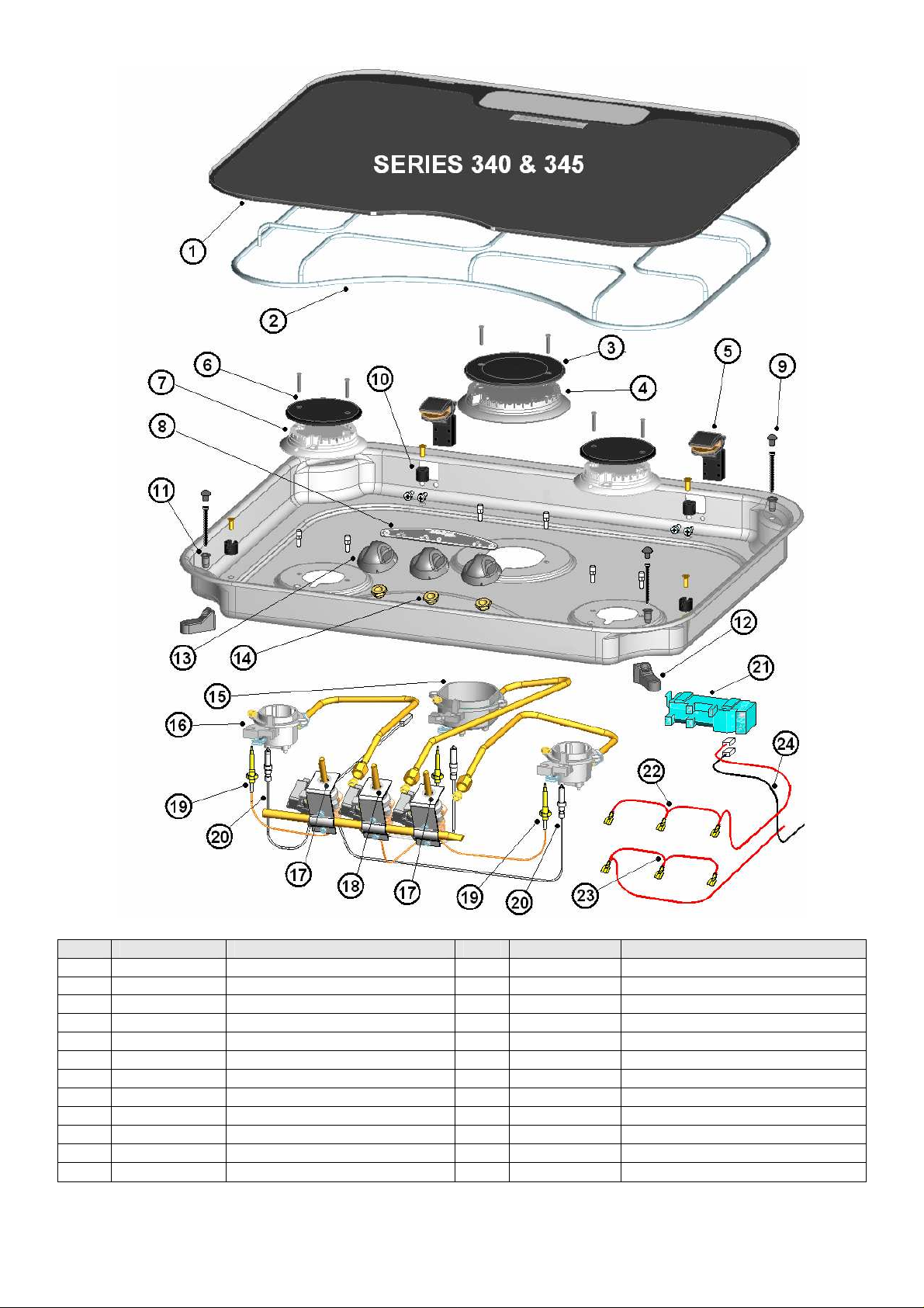
ITEM
1 S~G930.BK GLASS LID 2 S~PCC0691 PAN SUPPORT
3 S~PCC0833 RAPID BURNER CAP 4 S~PCC0832 RAPID BURNER SPREADER
5 S~PCC2003 HINGE 6 S~PCC0813 BURNER CAP
7 S~PCC0812 BURNER SPREADER 8 S~PCC1500 STICK ON FASCIA
9 S~PCX0390 BUMP STOP 10 S~PCC0647 PAN SUPPORT CLIP
11 S~PCX0415 FIXING BUSH 12 S~PCX0416 CLAMPING ARM
13 S~PCC0609 CONTROL KNOB 14 S~PCC0742 TAP FIXING NUT
15 S~PCC0799 RAPID BURNER CUP 16 S~PCC0797 BURNER CUP
17 S~PCC0737 CONTROL TAP (0.34 Bypass) 18 S~PCC07739 CONTROL TAP (0.45 Bypass)
19 S~PCC1130 THERMOCOUPLE 190MM 20 S~PCC1455 SPARK PROBE 600MM
21 S~PCC1403 SPARK GENERATOR (12V) 22 S~WIR0504 +VE WIRE TO GENERATOR
23 S~WIR0505 +VE WIRE TO BATTERY 24 S~WIR0200 -VE WIRE TO BATTERY
PART No DESCRIPTION ITEM PART No DESCRIPTION
2
Page 3

ITEM PART No DESCRIPTION ITEM PART No DESCRIPTION
1 S~G0940 GLASS LID 2 S~PCC0693
3 S~PCC0813 BURNER CAP 4 S~PCC0814
5 S~PCX0390 BUMP STOP 6 S~PCX0415 FIXING BUSH
7 S~PCC2003 HINGE 8 S~PCC647 CLIP, PAN SUPPORT
9 S~PCC1500 STICK ON FASCIA 10 S~PCX0416
11 S~PCC0609 CONTROL KNOB 12 S~PCC0742
13 S~PCC0797 BURNER CUP 14 S~PCC1190
15 S~PCC1453 SPARK PROBE 300MM 16 S~PCC0737
17 S~PCC1403 SPARK GENERATOR 18 S~WIR0505 +VE WIRE TO BATTERY
19 S~WIR0504 +VE WIRE TO GENERATOR 20 S~WIR0501 -VE WIRE TO BATTERY
21 S~PCC1132 THERMOCOUPLE 450MM 22 S~PCC1455 SPARK ELECTRODE 450MM
PAN SUPPORT
BURNER SPREADER
CLAMPING ARM
TAP FIXING NUT
THERMOCOUPLE 190MM
CONTROL TAP
3
Page 4
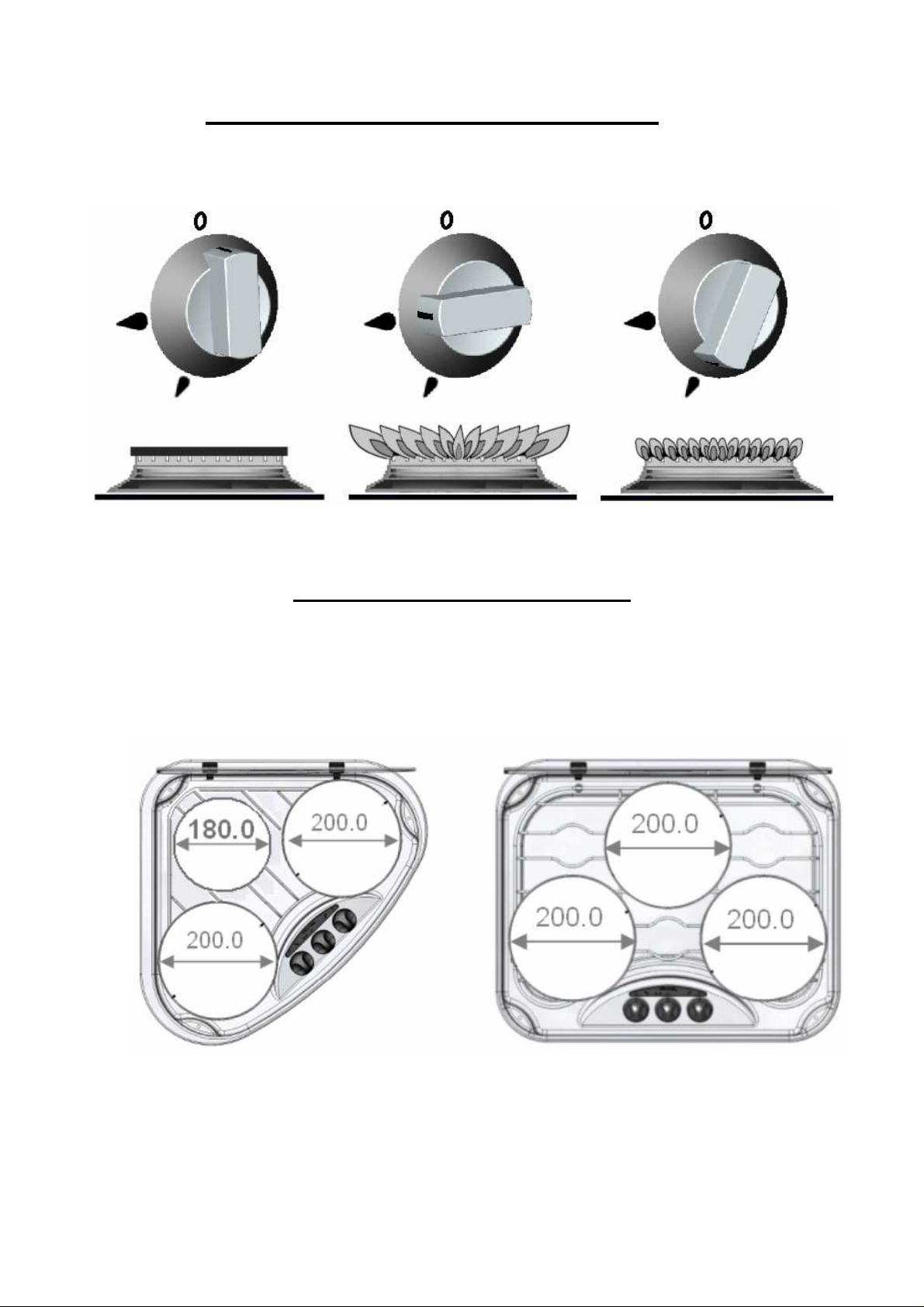
FIG. 1 OFF FULL RATE LOW RATE
CONTROL POSITIONS – ALL MODELS
FIG 2
RECOMMENDED PAN SIZES
SERIES 330 SERIES 340 & 345
4
Page 5

APPLIANCE LOCATION
Series 330, 340 & 345 the minimum allowable distance to combustible
materials is as shown below
FIG. 3
A= 200mm unless protected by a non-combustible heat barrier
B = 500mm minimum to fitment above appliance
5
Page 6

Fig. 4 WORKTOP CUTOUT – SERIES 330
A = Surface Mount Cutout
B = Flush Mount Cutout
6
Page 7

Fig. 5 WORKTOP CUTOUT – SERIES 340
A = Surface Mount Cutout
B = Flush Mount Cutout
7
Page 8

FIG. 6
SURFACE MOUNT FIXING – SERIES 330, 340 & 345
1 Surface mounting bezel 2 Glass Lid
3 Bump stop 4 Clamping bush
5 Worktop 6 Clamping arm
7 Clamping screw 8 Pressing
9 Flush mounting bezel
FIG. 7 FLUSH MOUNT FIXING – SERIES 330, 340 & 345
An additional 6mm deep rebate MUST be cut into the worktop to accept the
‘Flush Mounting Bezel’.
8
Page 9

CONTENTS
IMPORTANT
User’s Section
Specification ……………………………………………………Page 8
Introduction ……………………………………………………Page 9
Using the Appliance ……………………………………………………Page 10
Installation and Servicing
Installation Dimensions ……………………………………………………Pages 4-7
Specification ……………………………………………………Page 8
Installation Instructions ……………………………………………………Page 12
Maintenance & Servicing ……………………………………………………Page 13
Specification
Series 330 Series 340 Series 345
MODEL S~HB33000 S~HB34000 S~HB34500
Dimensions
(w x d X h)mm
480 X 480 X 100 540 X 445 X 100
540 X 445 X 100
Heat Input
Total heat input
Burner rating
Injector Size
Bypass Size
Spark Ignition
(Optional)
Sabaf 3 x 0.62mm Sabaf 3 x 0.62mm
Sabaf 3 x 0.34mm Sabaf 3 x 0.34mm
4.5kW 4.5kW 5.5Kw
3 x 1.5kW 3 x 1.5Kw
2 x 1.5kW
1 x 2.5kW
Sabaf 2 x 0.62mm
Sabaf 1 x 78mm
Sabaf 2 x 0.34mm
Sabaf 1 x 0.45mm
12v 12v 12v
Gas Category
CAT I3 + (28-30/37) CAT I
3
B/P
BUTANE (G30) 28 – 30 mbar BUTANE (G30) 30mbar
PROPANE (G31) 37mbar PROPANE (G31) 30mbar
• THIS APPLIANCE IS SUITABLE FOR USE WITH LIQUIFIED
PETROLEUM GAS (LPG) AND SHOULD NOT BE USED ON ANY
OTHER GAS
• USE ONLY THE GAS PRESSURES SPECIFIED ABOVE
• THIS APPLIANCE MUST BE EARTHED
9
Page 10

INTRODUCTION
IMPORTANT
This appliance is designed for cooking food, any other use is incorrect and dangerous. Failure
to install the appliance correctly or improper use could invalidate any warranty or liability claims
and lead to prosecution.
This appliance must be installed in accordance with the local, national and European
regulations in force. Particular attention shall be given to the requirements regarding ventilation.
Read the instructions before installing or using the appliance. The appliance MUST be installed
by an approved competent person.
Our policy is one of continuous development and improvement. Specifications and illustrations
may change subsequent to publication.
Provision of Ventilation
The use of a gas cooking appliance results in a production of heat and moisture in a room in
which it is installed. Ensure that the kitchen is well ventilated: keep natural ventilation holes
open or install a mechanical ventilation device, (mechanical extractor hood).
Prolonged intensive use of the appliance may call for additional ventilation, for example opening
a window, or more effective ventilation, for example increasing the level of mechanical
ventilation where present.
The room containing the cooker should have an air supply in accordance with local and
national/European standards.
Position
This appliance must be positioned free from draughts, which may affect the combustion, and in
a manner that will prevent the accumulation of unburnt gas. When in use ensure that air vents
are not inadvertently blocked or shut off.
Before using the appliance for the first time, remove any surface protection
film, ie plastic coating. Clean all surfaces with hot soapy water to remove any
residual protective covering of oil and rinse carefully.
10
Page 11

OPERATION
WARNING
IMPORTANT
Burner Operation
The burners on the appliance have fixed aeration and no adjustment is required. The burners
should flame as follows:-
Propane - The flames should burn quietly with a blue/green colour with no sign of yellow tips.
Butane - Normally on initial lighting, a small amount of yellow tipping will occur and then
• When cooking, young children should be kept away.
• Glass lids may shatter when heated. Turn off all burners before shutting
the lid.
• Spillage on the lid surface should be removed before opening the lid
slightly increases as the burner heats up.
• Series 330 - will support 200mm Ø pans on the outer burners and
180mm Ø pan on the central burner – see Fig. 2
• Series 340 & 345 will support 3 x 200mm Ø pans – see Fig. 2
• Avoid old or misshapen pans as these may cause instability.
• The lid must be opened fully prior to using the hotplate burners.
1. Ensure gas cylinder/supply is connected and turned on. In the event of a gas smell turn off at
gas cylinder/mains and contact supplier.
2. Flame supervision: Each burner is controlled individually and is monitored by a
thermocouple probe. In the event of the burner flames being accidentally extinguished, turn
off the burner control and do not attempt to re-ignite the burner for at least one minute.
3. To light: Push in the control knob and turn to full rate – see Fig.1. Hold a lighted match or
taper to the burner and push the control knob in and hold. It is necessary to hold the knob
depressed after the burner has ignited for approximately 10 - 15 seconds, to allow the
thermocouple probe to reach temperature, before releasing the knob. Should the flame go
out when the knob is released, the procedure should be repeated holding the knob
depressed for slightly longer.
4. For models fitted with optional Spark Ignition the procedure is similar:-
Models with Auto Spark Ignition – pushing the control knob automatically starts the
spark ignition circuit . To light the burner follow the procedure in (3) above except the
burner is automatically ignited.
Models with Manual Spark Ignition – follow the procedure in (3) above, except that the
burner can be ignited by depressing the ignition button located on the fascia.
If the burner has not lit within 15 seconds the control knob should be released and the
burner left for at least 1 minute before a further attempt to ignite the burner.
5. For simmering, turn the knob further anti-clockwise to the low rate position.
6. To turn off: Turn the control knob until the line on the control knob is aligned with the dot on
the control panel. Always make sure the control knob is in the off position when you have
finished using the hotplate burners.
11
Page 12

OPERATION
WARNING
DO'S AND DON'TS
DO read the user instructions carefully before using the appliance for the
DO allow the burners to heat before using for the first time, in order to expel any
DO clean the appliance regularly.
DO remove spills as soon as they occur.
DO check that controls are in the off position when finished.
DO NOT allow children near the appliance when in use. Turn pan handles away from the
DO NOT allow fats or oils to build up in the base of the hotplate.
DO NOT use abrasive cleaners or powders that will scratch the surfaces of the hotplate.
DO NOT under any circumstances use the appliance as a space heater.
LEAKS
If a smell of gas becomes apparent, the supply should be turned off at the cylinder
IMMEDIATELY.
Extinguish naked lights including cigarettes and pipes. Do not operate electrical switches. Open
all doors and windows to disperse any gas escape. Butane/Propane gas is heavier than air;
any gas escaping will therefore collect at low level. The strong unpleasant smell of gas will
enable the general area of the leak to be detected. Check that the gas is not escaping from an
unlit appliance. Never check for leaks with a naked flame; leak investigation should be carried
out using a leak detector spray or soapy solution.
The Glass lid has the tendency to snap shut towards the end of lowering.
This is caused by the travel lock action of the hinges as it is activated. Make
sure all fingers are removed from appliance when closing the lid.
first time.
smells before the introduction of food.
front so that they cannot be caught accidentally.
12
Page 13

INSTALLATION
REGULATIONS AND STANDARDS
In your own interest of safety this appliance must be installed in accordance with the local,
national and European regulations in force. Particular attention shall be given to the
requirements regarding ventilation. Read the instructions before installing or using the
appliance. The appliance MUST be installed by an approved competent person.
Failure to install the appliance correctly could invalidate any warranty or liability claims and lead
to prosecution.
VENTILATION
This appliance is suitable for installation into Holiday Homes, Touring Caravans and Boats. In all
cases the national standards with regard to ventilation for the particular vehicle into which the
appliance is to be installed must be adhered to.
The European Standard EN1949 - "Specification for the installation of LPG systems in leisure
and other road vehicles", specifies that all appliances be installed in accordance with the
manufacturers instructions, including the adequate provision to avoid the accumulation of unburnt gases. We recommend a vent in the floor (minimum=130mm2 , maximum=3850mm2)
venting to the outside, to avoid the accumulation of un-burnt gases.
LOCATION OF APPLIANCE
This appliance maybe installed in a kitchen/kitchen diner but NOT in a room containing a bath or
a shower. LP gas appliances must not be fitted below ground level. e.g. in a basement.
POSITION
A direct distance of 200mm must exist between the edge of the burner and combustible material
unless protected by a layer of non-combustible material - see fig. 3. For models with a glass lid,
the distance to the rear of the appliance can be reduced to 110mm.
All combustible materials such as curtains and shelves must be kept well clear of the appliance.
Any fitments such as a cupboard above the appliance must have a minimum clearance of
500mm between the fitment and the top of the pan support.
This appliance must be positioned free from draughts, which may affect the combustion, and in
a manner that will prevent the accumulation of unburnt gas. When in use ensure that air vents
are not inadvertently blocked or shut off.
The underside of the appliance must be shielded. It is recommended the shield is fabricated
from non-combustible material, but if the enclosure is manufactured from combustible material,
a minimum air space of 100mm must exist between the material and the lowest part of the
appliance. THIS AIR SPACE MUST BE WELL VENTILATED
13
Page 14

INSTALLATION
IMPORTANT
INSTALLATION
The appliance can be installed either onto the worktop or inset – ie flush fitting. A cut-out should
be prepared in the worktop as shown in Figs. 4 & 5. If the appliance is to be flush mounted the
worktop cut-out will require an additional rebate as detailed in Figs. 4 & 5. and shown in Fig. 7.
Care should be taken to position the appliance central in the worktop cut-out to ensure an air
gap is maintained between the appliance and the sides of the cut-out. The appliance may then
be fixed in position by tightening the clamp screws.
GAS CONNECTION
The gas connection is made to a 8mm Ø inlet pipe, beneath and to the rear of the appliance.
Prior to connection remove the plastic protection plug from the fitting. It is recommended that
the appliance be connected by copper pipe, rubber tubing MUST NOT be used.
• Where Spark Ignition is fitted the appliance MUST be earthed
• After Installation the appliance MUST be tested for soundness
• The gas supply input pressure to which this appliance is connected, MUST
not rise or fall by more than 2.5 mbar (butane/propane) from nominal when
ALL appliances connected to the supply are OPERATED simultaneously. If
this appliance is not installed in accordance with the instructions and
tolerances detailed herein, we the manufacturer can not be held responsible
for any problems that occur, or poor performance that is
perceived/witnessed.
MAINTENANCE & SERVICING
This appliance needs little maintenance other than cleaning. All parts should be cleaned using
warm soapy water. Do not use abrasive cleaners, steel wool or cleansing powders. When
cleaning the burner ring it is essential to ensure that the holes do not become blocked. The
control knobs are a push fit and can be removed for cleaning. They are interchangeable without
affecting the sense of operation.
ALL SERVICING MUST BE CARRIED OUT BY AN APPROVED COMPETENT PERSON.
AFTER EACH SERVICE THE APPLIANCE MUST BE CHECKED FOR GAS SOUNDNESS.
14
 Loading...