

Page 1
THETA DIGITAL
Generation VIII Series 3
Owner’s Manual
V 2.00
Digital Done Right
™
Page 2

PREFACE
CONGRATULATIONS
You have just acquired the most advanced component for the processing and conversion of digital to analog
signals to have been developed.
IMPORTANT
Save all packaging in a dry place away from fire hazards. Your Generation VIII is a precision electronic
instrument and should be properly packaged any time shipment is made. In the unlikely event that you have to
return your Generation VIII to the factory for service, or if you send it to us for updating, the original packaging
will best protect the unit from shipping damage.
In order to achieve the fullest flexibility and enjoyment from your Generation VIII, we at Theta recommend that
you read this manual in full before connecting the unit to your audio/video system.
WARNING
United Stated law prohibits disposition of these commodities to Libya, Laos, North Korea, Cambodia or Cuba
unless otherwise authorized by the United States.
NOTE:
This equipment has been tested and found to comply with the limits for a Class B digital device, pursuant to Part
15 of the FCC rules. These limits are designed to provide reasonable protection against harmful interference in
a residential installation. This equipment generates, uses and can radiate radio frequency energy and, if not
installed and used in accordance with the instructions, may cause harmful interference to radio
communications. However, there is no guarantee that interference will not occur in a particular installation. If
this equipment does cause harmful interference to radio and television reception, which can be determined by
turning the equipment off and on, the user is encouraged to try to correct the interference by one or more of the
following measures:
* Reorient or relocate the receiving antenna.
* Increase the separation between equipment and receiver.
* Connect the receiver into an outlet on a circuit different from that to which the Generation VIII is connected.
Acknowledgments
© 2003-2011 Theta Digital. All rights reserved.
This manual is also available for download as a PDF file at Theta Digital’s website: http://www.thetadigital.com
No part of this publication may be reproduced or transmitted in any form or by any means, electronic or
mechanical, for any purpose, without the express written permission of Theta Digital.
ii
Page 3
The lightning flash with arrowhead symbol, within an equilateral
triangle, is intended to alert the user to the presence of uninsulated
“dangerous voltage” within the product’s enclosure that may be of
significant magnitude to constitute a risk of electric shock to persons.
The exclamation point within an equilateral triangle is intended to alert
the user to the presence of important operating and maintenance
(servicing) instructions in the literature accompanying the product.
WARNING
TO REDUCE THE RISK OF FIRE OR ELECTRIC SHOCK,
DO NOT EXPOSE THIS PRODUCT TO RAIN OR MOISTURE
CAUTION: TO PREVENT ELECTRIC SHOCK, DO NOT USE THE (POLARIZED) PLUG WITH AN
EXTENSION CORD, RECEPTACLE OR OTHER OUTLET UNLESS THE BLADES CAN BE FULLY
INSERTED TO PREVENT BLADE EXPOSURE.
iii
Page 4

Generation VIII Identification Record
This information is for your records and for future identification of the Generation VIII. Please take a moment
to fill out all pertinent data now, and as upgrades and/or options are installed. Whenever upgrades,
inquiries, service, repair and/or changes are requested, the serial number will be required.
SERIAL NUMBER
DATE PURCHASED
DEALER’S NAME
DEALER’S ADDRESS/PHONE
INSTALLED CARDS/OPTIONS/UPGRADES
(Date of installation)
(Date of installation)
(Date of installation)
(Date of installation)
(Date of installation)
(Date of installation)
iv
Page 5

SAFETY PRECAUTIONS
Please carefully read each item of the operating instructions and safety precautions before using this
product. Use extra care to follow the warnings written on the product itself and/or in the operating
instructions. Keep the operating instructions and safety precautions for future reference.
CAUTION: TO REDUCE THE RISK OF ELECTRICAL SHOCK, DO NOT REMOVE ANY OF THE COVER
PANELS.
NO USER-SERVICEABLE PARTS INSIDE. REFER ALL SERVICING TO QUALIFIED SERVICE
PERSONNEL ONLY.
TO PREVENT FIRE OR SHOCK HAZARD, DO NOT ALLOW LIQUIDS TO SPILL OR OBJECTS TO FALL
INTO ANY OPENINGS OF THE PRODUCT.
THIS UNIT IS SUPPLIED WITH A 3 PIN GROUNDED AC PLUG. ALWAYS INSERT THE AC PLUG INTO
A GROUNDED OUTLET. DO NOT REMOVE THE GROUND PIN OR DISABLE THE GROUND FOR ANY
PURPOSE.
BEFORE MAKING ANY CONNECTIONS TO THE GENERATION VIII, FIRST TURN OFF THE POWER
AND THEN DISCONNECT THE AC POWER CORD.
WHEN INSTALLING THE GENERATION VIII IN YOUR SYSTEM, MAKE CERTAIN TO ALLOW A
MINIMUM OF 3 INCHS OF VENTILATION ON EACH SIDE OF THE UNIT. ALSO ALLOW AT LEAST 3½
INCHS OF VENTILATION SPACE ABOVE THE UNIT. IMPROPER VENTILATION OF THE UNIT MAY
CAUSE OVERHEATING, WHICH MAY DAMAGE THE UNIT AND CAUSE A FIRE. PLACE THE UNIT ON
A SOLID SURFACE ONLY. I.E. NOT ON CARPET, ETC.
DO NOT PLACE THE GENERATION VIII NEAR HEAT SOURCES SUCH AS DIRECT SUNLIGHT,
STOVES, HEAT REGISTERS, RADIATORS OR OTHER HEAT PRODUCING EQUIPMENT.
TO PREVENT DAMAGE TO THE ANALOG OUTPUT CIRCUITRY, BE CERTAIN NOT TO SHORT THE
OUTPUT SIGNAL PIN(S) TO GROUND. ENSURE THAT YOUR AUDIO OUTPUT CABLES DO NOT
HAVE ANY INTERNAL SHORTS BEFORE CONNECTING THEM TO THE GENERATION VIII.
IF REPLACEMENT OF THE AC LINE FUSE BECOMES NECESSARY, REPLACE ONLY WITH SAME
VALUE AND TYPE OF FUSE. NEVER BYPASS THE FUSE.
IF THE AC CORD BECOMES DAMAGED, DO NOT USE IT. IMMEDIATELY REPLACE IT WITH A NEW
ONE OF THE SAME OR BETTER RATING.
AFTER MARKET and THIRD PARTY MODIFICATIONS
Please note that any after market and/or third party modifications will void the warranty. In the case of
changing the feet on a unit, in order to prevent any damage (which will also not be covered under warranty),
please verify that the screws being used to secure non Generation VIII feet do not screw any deeper into the
chassis than the original ones. The original screw is 1/4-20 by 3/8 and goes into the chassis 1/4 inch MAX.
v
Page 6

Table of Contents
PREFACE...........................................................................................................................................................ii
WARNING......................................................................................................................................................iii
Generation VIII Identification Record.............................................................................................................iv
SAFETY PRECAUTIONS...............................................................................................................................v
List of Figures................................................................................................................................................ vii
List of Tables................................................................................................................................................. vii
INTRODUCTION................................................................................................................................................1
Getting to know your Generation VIII..............................................................................................................1
IMPORTANT NOTICE....................................................................................................................................2
Reference Manual Conventions......................................................................................................................2
Glossary of Terms and Abbreviations.............................................................................................................3
Generation VIII Block Diagram .......................................................................................................................4
Front Panel Layout..........................................................................................................................................5
Rear Panel Layout ..........................................................................................................................................6
Menu Maps .....................................................................................................................................................7
Setup Menu Pages......................................................................................................................................7
Remote Control...............................................................................................................................................8
Introduction to the User interface....................................................................................................................9
OPERATIONS..................................................................................................................................................10
Input Select Buttons......................................................................................................................................10
Changing Inputs ........................................................................................................................................10
SETUP ..........................................................................................................................................................11
Jack and Input Names...............................................................................................................................11
Clocking.....................................................................................................................................................12
Unity Gain..................................................................................................................................................12
Input Offset Level ......................................................................................................................................12
Burn In.......................................................................................................................................................13
Remote Triggering.....................................................................................................................................13
RS232........................................................................................................................................................14
IR Source...................................................................................................................................................15
Using Generation VIII as an External DAC...............................................................................................15
Screensaver ..............................................................................................................................................16
Initial Volume Level ...................................................................................................................................16
Serial Number/Software Versions.............................................................................................................17
BALANCE Function.......................................................................................................................................17
APPENDIXES...................................................................................................................................................18
Appendix A Troubleshooting Guide ........................................................................................................19
Appendix B Wiring Diagrams..................................................................................................................20
Appendix C Upgrading/Re-installing Generation VIII Software...............................................................22
Appendix D Remote Extender Jack Technical Description and Protocol...............................................23
Appendix E RS232 Protocol....................................................................................................................24
RS232 Hardware Connections..................................................................................................................24
Appendix F Specifications.......................................................................................................................30
Warranty Information........................................................................................................................................32
vi
Page 7

List of Figures
Figure 1 - Generation VIII Block Diagram ..........................................................................................................4
Figure 2 - Front Panel Layout.............................................................................................................................5
Figure 3 - Rear Panel Layout .............................................................................................................................6
Figure 4 - Setup Menu Pages.............................................................................................................................7
Figure 5 - Remote Control..................................................................................................................................8
Figure 6 - Front Panel Display of the INPUT SELECT page............................................................................10
Figure 7 - Front Panel Display of the INPUT SELECT page when Fixed Volume Controls are installed........10
Figure 8 - Front Panel Display of the Jack Map and Input Name SETUP menu.............................................11
Figure 9 - Front Panel Display of the Input Clocking SETUP menu.................................................................12
Figure 10 - Front Panel Display of the Unity Gain SETUP menu.....................................................................12
Figure 11 - Front Panel Display of the Offset Level SETUP menu..................................................................13
Figure 12 - Front Panel Display of the Burn In Signal SETUP menu...............................................................13
Figure 13 - Front Panel Display of the Remote Trigger SETUP menu ............................................................13
Figure 14 - Front Panel Display of the RS 232 SETUP menu .........................................................................14
Figure 15 - Front Panel Display of the IR Source SETUP menu .....................................................................15
Figure 16 - Front Panel Display of the Ext Vol SETUP menu..........................................................................15
Figure 17 - Front Panel Display of the SETUP page 8 – Screensaver............................................................16
Figure 18 - Front Panel Display of the Initial Volume SETUP menu................................................................16
Figure 19 - Front Panel Display of the Info menu.............................................................................................17
Figure 20 - Front Panel Display of the Balance Menu......................................................................................17
Figure 21 - Examples of Typical In and Out Connections................................................................................20
Figure 22 - Example of Connections to/from a Casablanca II/III Digital Out Card...........................................21
List of Tables
Table 1 - Glossary of Terms and Abbreviations.................................................................................................3
Table 2 – Display Jack Name Abbreviations & Definitions ..............................................................................11
Table 3 – Troubleshooting Guide.....................................................................................................................19
vii
Page 8

INTRODUCTION
Welcome to a new world of possibilities. Generation VIII is by far the most advanced digital to analog
converter available today. It offers the advantages of Theta’s legendary mastery in digital signal processing
and sound quality unapproachable by any other equipment.
Getting to know your Generation VIII
Despite the Generation VIII’s great technical sophistication, we believe in making it as easy as possible for
you to use. We think you’ll enjoy the intuitive way the Generation VIII works. Rather than offer a frustrating
bewilderment of little used functions in constant view, vying for your attention, Generation VIII is structured
systematically by function.
This Generation VIII has been put through a rigorous and unique testing procedure that insures that it will
last for many years with minimal service requirements. This procedure includes the following:
• All assembled circuit boards are given a thorough visual inspection and are then tested in a benchreference Generation VIII.
• The tested, assembled circuit boards are then installed in a new Generation VIII and the whole unit is
tested for every function and parameter.
• The unit is put on a burn-in torture rack for 100 hours to test for any possible component failures.
• The Generation VIII is tested on an audio analyzer for all pertinent parameters.
• The Generation VIII is put through a final bench test wherein every possible feature, mode and
parameter is checked.
• The unit has all remaining chassis components installed and then undergoes a complete visual
inspection, which assures that all Generation VIII’s meet visual specifications.
• The unit is then put through a critical listening test.
Burn In Time
This unit has a break in period of about 1 week during which continuous improvement in sound quality will be
observed. It is recommended that music or the internal burn-in signal be played continuously through the
unit during this time to expedite the break in period.
1
Page 9

IMPORTANT NOTICE
I. Due to the computer-based circuitry used in Theta products, it is imperative that the Generation VIII
be connected to a ground via its three wire AC power cord. It is important that the AC power outlet
which the Generation VIII is plugged into, is actually grounded. Failure to do so will severely
compromise the performance, reliability and safety of use of the Generation VIII.
II. It is also important to prevent discharge of static electricity when connecting other components and
cables to the Generation VIII. When connecting cables, simply place one hand on top of the
Generation VIII and then grasp the metal “barrel” of the cable with the other hand and plug (unplug)
the cable into (from) the appropriate jack on the Generation VIII.
III. The Generation VIII, as with all electronic equipment, is susceptible to static discharges. Resetting
the unit may be required if anomalies occur after receiving a static discharge. In this case, put the
unit in standby and turn off the rear panel power switch for 2 minutes, and then turn it on again.
IV. Ventilation is an important issue when placing the Generation VIII in a system. Make certain that the
Generation VIII is placed in a well-ventilated area or rack unit. There must be a clear path for cool
air to get into the unit, and for heat to escape.
V. Please take note that some powerline conditioners defeat the AC power ground on their outlets. If
the intention is to plug the Generation VIII into a line conditioner, check with your dealer to make
certain that the particular conditioner that is intended for use DOES NOT DEFEAT THE AC
GROUND on its AC outlets.
VI. DO NOT remove any cover panels from the Generation VIII, as there are no user serviceable
components inside. Refer updating and servicing to Theta qualified service personnel only.
VII. Should the Generation VIII need to be reset, it must be put in standby first via the front panel power
button. Then the rear panel power switch is to be turned off for at least 2 minutes.
VIII. The Generation VIII can be susceptible to excessive RF. End caps in all unused inputs will improve
the sound quality and may reduce the susceptibility to RF induced anomalies.
Reference Manual Conventions
For clarity purposes, references to buttons, LED’s and display parameters will be shown in bold capital
letters.
2
Page 10

Glossary of Terms and Abbreviations
TERM DEFINITION
AES/EBU (Audio Engineering Society) / (European
Broadcasters Union)
Analog-to-Digital Converter A device that converts analog signals into a digital format. Once
Balanced Audio Signals Signals that are carried on three-conductor cables, with two of the
DAC Digital to Analog converter
dB Decibel, a relative unit of loudness.
Digital-to-Analog Converter (DAC) A device that converts digital signals into an analog format.
DSP Digital Signal Processor (Processing)
Hz (Hertz) A unit of frequency.
IR Infrared. A wireless method of data transmission.
mS Millisecond, or 1/1000 of a second.
Oversampling The process of taking more samples than is required in order to more
Sampling Rate The rate at which an analog (real world) signal is converted into digital
Single-Ended or SE, aka Unbalanced Audio Signals Signals that are carried on two-conductor cables, one “hot”, or signal, and
S/PDIF Interface (Sony/Phillips Digital Interface
format)
TRS Tip, Ring, Sleeve. Names of the 3 connecting elements of a stereo phono
VFD Vacuum Florescent Display
A three wire balanced digital audio standard. This interface uses a 3-pin
XLR type connector and allows for data communication between digital
audio equipment.
encoded, all audio is stored or processed as a series of numbers rather
than as the audio itself.
conductors carrying the same signal 180° out of phase and the third as
ground. Balanced connections usually cost more than unbalanced
connections, but are less susceptible to picking up hum and prevent
interference with low-level signals.
accurately reconstruct a digitized signal for playback in the analog
domain.
numeric values.
one ground.
A digital audio interconnection standard, developed jointly by Sony and
Phillips.
jack or plug.
Table 1 - Glossary of Terms and Abbreviations
3
Page 11
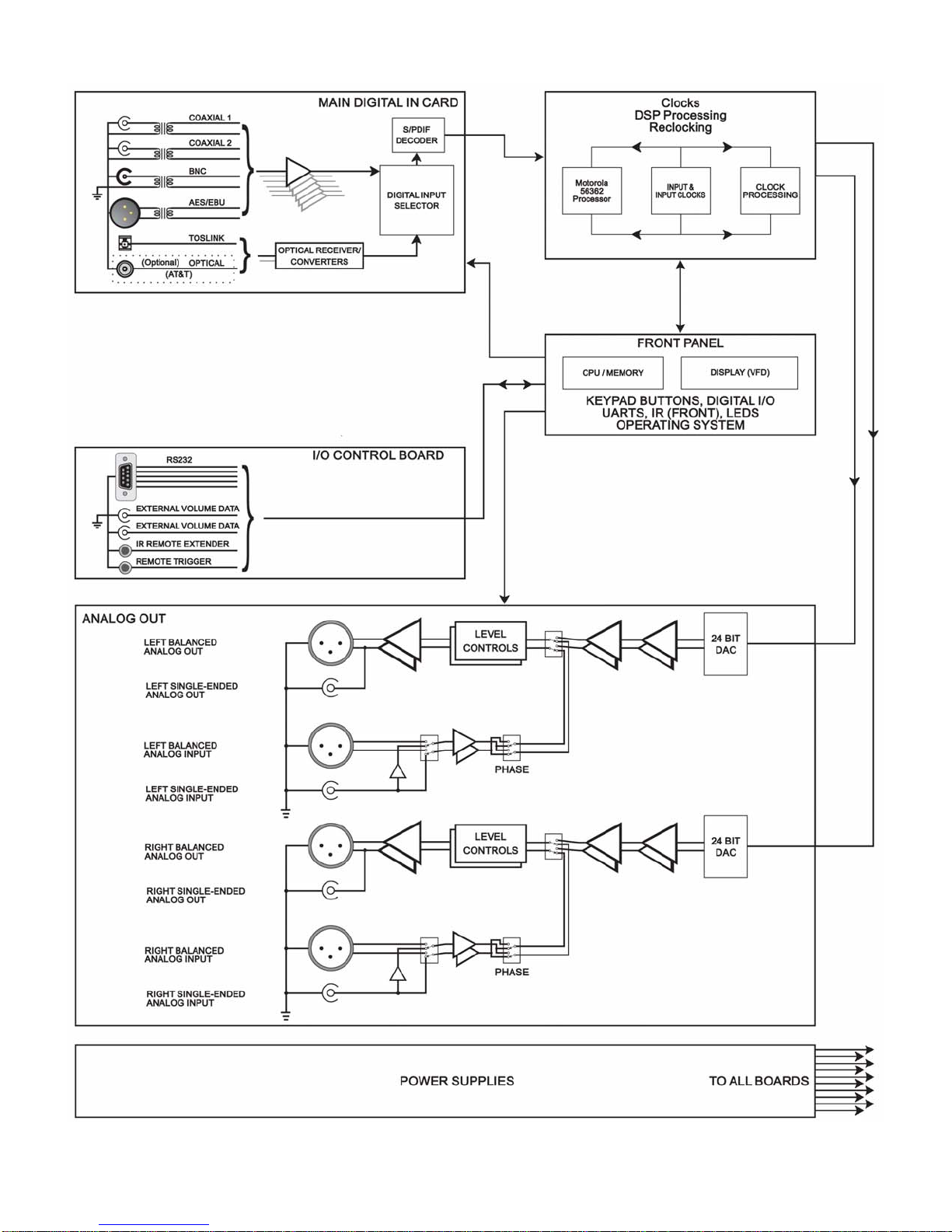
Generation VIII Block Diagram
Figure 1 - Generation VIII Block Diagram
4
Page 12
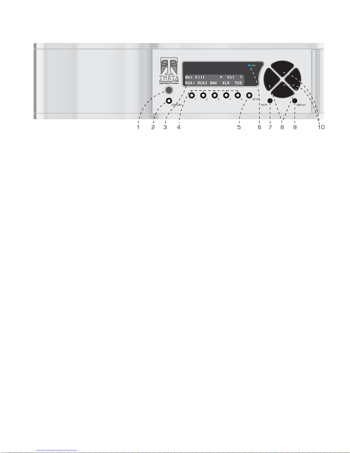
Front Panel Layout
Figure 2 - Front Panel Layout
1. Remote IR receiver.
2. STANDBY button/LED. After the rear panel MAIN POWER switch is turned on, press the front panel STANDBY button to exit
the standby mode. The Generation VIII will quickly initialize. The VFD will default to the last selected INPUT. Pressing
STANDBY again will place the Generation VIII into standby mode and the LED in the front panel STANDBY button will light.
Each time the Generation VIII is put into standby, the VFD will “exercise” itself for 10 seconds by illuminating all pixels. (This
will enhance the lifetime of the VFD).
3. 24 character by 2 row Vacuum Florescent Display (VFD).
4. Buttons 1 through 5. Used to select a desired INPUT, or parameter to change in the SETUP menus. The LED in the button
lights when the button is pressed. These buttons are referred to as the INPUT SELECT buttons.
5. SETUP button. Used to access the SETUP menus, for setting all user parameters.
6. LOCK light. Lights when a valid digital signal is detected on the currently selected input.
7. MUTE button. Mutes/unmutes all audio outputs. Not active when optional fixed volume cards are installed.
8. LEVEL LEFT and RIGHT buttons. Shifts audio balance to the left and right, or adjusts the master volume within submenus
when the LEVEL UP/DOWN buttons are to be used for editing parameter values.
9. The DISPLAY button will toggle the VFD brightness between off, ¼, ½, ¾ and full brightness.
10. LEVEL UP and DOWN buttons. Increases/decreases master volume. Also used to increment/decrement values in the
SETUP menus.
5
Page 13

Rear Panel Layout
1. Right Balanced Output.
2. Right Single-Ended Output (RCA).
3. Right Analog Input (RCA)
4. Right Balanced Analog Input.
5. Left Balanced Output.
6. Left Single-Ended Output (RCA).
7. Left Analog Input (RCA)
8. Left Balanced Analog Input.
9. AC Power input connector: 3 wire, IEC 320 standard with an EMI filter.
10. Fuse Holder. Fuse @ 100 & 110V = 630mA/250V, Fuse @ 220V = 3/8A/250V.
Figure 3 - Rear Panel Layout
11. Main Power Switch. Master power switch. Disconnects AC to all circuits. It is recommended that this be left
ON at all times during regular use with the exception of whenever cables are connected/disconnected or when
the unit is not going to be used for an extended period of time. When this switch is turned on, the display will
momentarily show the unit’s serial number.
12. IR Remote Extender jack. An externally mounted (remote) Infrared Receiver (IR) plugs into this miniature stereo
phono jack. The signal must
be demodulated. Please refer to Appendix D on page 23 for additional information.
13. Remote Trigger jack. Activated/deactivated (toggle) when the STANDBY button is pressed. The trigger can be
set to be either an input or output and function with either 12VDC or a 12V pulse (variable duration). The default
is a DC Output.
14. RS232 connector (DB9).
15. External Volume Data inputs. When the Generation VIII is used as an external DAC with the Theta Casablanca
or Casa Nova, output volume can be controlled from the processor. This is a proprietary digital data input.
16. Optional optical input (AT&T)
17. TosLink optical input
18. AES/EBU Digital input.
19. BNC digital input
20. Coaxial digital input # 2 (RCA)
21. Coaxial digital input # 1 (RCA)
22. Auxiliary Digital Input board.
6
Page 14

Menu Maps
Setup Menu Pages
Within the Setup feature, following are all possible Setup menu pages:
** Not accessible when fixed volume option is installed.
Figure 4 - Setup Menu Pages
7
Page 15

Remote Control
1. Standby button. After the rear panel MAIN POWER
switch is turned on, press the front panel STANDBY
button to exit the standby mode. The Gen VIII will
quickly initialize. The VFD will default to the last
selected INPUT. Pressing STANDBY again will
place the Generation VIII into standby mode and the
LED in the front panel STANDBY button will light.
Each time the unit is put into standby, the VFD will
“exercise” itself for 10 seconds by illuminating all
pixels. (This will enhance the lifetime of the VFD).
The Standby button is inactive when the Generation
VIII is in SETUP.
2. Input Select buttons 1 through 5. Used to select a
desired INPUT, or to change a parameter when in a
submenu. The LED in the button lights when the
button is pressed.
3. The DISPLAY button will cycle the VFD brightness
through full brightness, ¾, ½, ¼ and off.
4. Mute button. Mutes/unmutes all audio outputs. Not
active when optional fixed volume cards are installed.
5. Setup button. Used to enter/exit the SETUP menus,
when setting all user parameters.
6. Level Up/Down buttons. Increases/decreases
master volume. Also used to increment/decrement
values in the SETUP menus.
7. Level Left/Right buttons. Shifts audio balance to
the left and right, or adjusts the master volume within
submenus when the LEVEL UP/DOWN buttons are
used for parameter value editing.
8. Phase button. Toggles the phase (0-180°) of all
speaker outputs.
Figure 5 - Remote Control
: When operating the hand held remote control, point it at the remote sensor on the Generation VIII’s front panel. The
Note
remote control can be used 3 to 20 feet from the Generation VIII and within a 30o angle from each side of the sensor.
Exposing the remote sensor to direct sunlight or strong light may cause faulty operation.
8
Page 16

Introduction to the User interface
The menu system within the Generation VIII is no deeper than 2 layers. When the SETUP button is pressed the
first setup page is shown. There is a “>” symbol above the # 5 button at all times when in Setup. This indicates
that there is another page of setup parameters. While in setup, simply pressing button # 5 repeatedly will take
the user through all of the SETUP pages. This is a loop and will ultimately bring the user back to the first
SETUP page. Please refer to Figure 4 for an overall view of all SETUP menus.
The first four SETUP menu pages contain parameters that can be stored uniquely for each of the five INPUT
SELECT buttons. The remaining SETUP pages are parameters which are global to the Generation VIII.
Once a parameter is selected for editing, pressing the LEVEL UP/DOWN buttons edits the parameter value,
storing it at the same time. On any SETUP page, the LEVEL LEFT/RIGHT buttons will adjust the master
volume.
To exit the SETUP menu, simply press the SETUP button again.
* * *
In the past, Theta has offered various options with their products. With the Generation VIII, most of these
options are pre-installed into the ‘base’ model. One important option remains - the ability to have the
Generation VIII be both a processor and a preamp. In older Generation VIIIs, this was achieved by having
either fixed volume controls or variable volume controls installed at the time of purchase. With software version
0.26 and higher, all new units will have variable volume controls installed as the user can program any input(s)
to be fixed or variable.
Generation VIII’s with fixed volume controls can use software version 0.26 or higher but will not have the benefit
of the volume related features. If desired, these Generation VIII’s can have their volume cards updated.
This manual describes the operations and menus as if the variable volume controls are installed. In each
section, menus, structures and instructional changes are indicated where they apply to a Generation VIII with
fixed volume controls.
9
Page 17

OPERATIONS
This section describes the functionality of each button on the Generation VIII’s front panel.
Input Select Buttons
When the Generation VIII is first powered up via the MAIN POWER switch on the back panel, it will check all
installed software and hardware, momentarily display the unit serial number, and then revert to the standby mode.
The STANDBY LED will be lit.
After pressing the STANDBY button on the front panel, the display will show the start-up routine and then the
INPUT SELECT page, shown below in Figure 6. As this menu appears, the STANDBY LED turns off. This
display will be on during normal operation and will change only when the SETUP or balance (LEVELS
LEFT/RIGHT) buttons are pressed.
Changing Inputs
The INPUT NAMES shown in this figure are the default names only, and may differ from the user’s setup. There
are a total of 5 inputs. Buttons 1 through 5 are used to select a desired input, or audio source. The LED in the
selected button will illuminate when pressed. When the Generation VIII exits the standby mode, the last active
INPUT SELECT will be selected.
Figure 6 - Front Panel Display of the INPUT SELECT page
Pressing the LEVEL UP/DOWN buttons will adjust the master volume for all speakers. This value ranges from 0
to 86, relative maximum.
It is important to note that if the Fixed Volume Control option is installed, the “Vol” parameter in the display will
indicate the word “Fixed”. If the LEVEL UP/DOWN; MUTE; and/or BALANCE buttons are pressed, the word
Fixed will flash and the above mentioned buttons will have no effect. An example of this menu is shown in Figure
7 below.
Figure 7 - Front Panel Display of the INPUT SELECT page
when Fixed Volume Controls are installed
* * *
The DISPLAY button will cycle the VFD brightness through full brightness, ¾, ½, ¼ and off.
The MUTE button mutes/unmutes all audio outputs. It is not active when optional fixed volume cards are
installed.
10
Page 18

SETUP
This function provides access to a series of submenus that will allow the configuration of the Generation VIII. In
this section, each feature of the SETUP menu is discussed in detail along with a diagram of each VFD display.
Pressing the SETUP button once changes the front panel display to the first page of the SETUP menu, shown in
Figure 8. Pressing button # 5 (>) allows the user to enter into a series of Setup menu pages that permit the
configuration of all parameters that are programmable, both by INPUT SELECT button and global.
The master volume level is shown in the upper right corner of each SETUP menu.
Figure 8 - Front Panel Display of the Jack Map and Input Name SETUP menu
Jack and Input Names
Each physical input jack can be assigned, or “mapped” to any INPUT SELECT button. INPUT SELECT button
names can be changed.
Pressing button # 1 allows the user to select which INPUT is to be edited. Use the LEVEL UP/DOWN buttons to
change the parameter.
Use button # 2 to reassign a rear panel input jack to the currently selected front panel INPUT SELECT button.
Button # 4 allows the user to select a name for the currently selected INPUT, or INPUT SELECT button. In
Figure 8, the rear panel RCA 1 jack is mapped to INPUT SELECT button # 1 and INPUT SELECT # 1 is named
CD.
The possible INPUT SELECT names are as follows:
RCA1, RCA 2, BNC, XLR, TOS, Opti, Abal, A se, CD, CD 1, CD 2, DVD, DVD1, DVD2, Phon, Tune, AM, FM, TV,
and “number’. If ‘number’ is selected, the name will be the number of the currently selected INPUT SELECT.
From this SETUP menu, pressing button # 5 takes the user to the second page, shown in Figure 9.
Jack Definition
RCA 1 Rear panel RCA 1 input jack
RCA 2 Rear panel RCA 2 input jack
BNC Rear panel BNC input jack
XLR Rear panel AES/EBU input jack
TOS Rear panel TosLink input jack
Optical Rear panel Optical input jack
Ana Bal Rear panel Balanced Analog input jack
Ana S.E. Rear panel Single-Ended Analog input jack
Table 2 – Display Jack Name Abbreviations & Definitions
11
Page 19

Clocking
A re-clocking circuit typically converts poor quality jitter-ridden signals into high-quality transformer-isolated ones.
The Generation VIII uses this standard design to re-clock. The Generation VIII also has an advanced proprietary
synthesized anti-jitter circuit known as “Jitter Jail”. Either clocking type can be selected by the user, via button #
2.
Figure 9 - Front Panel Display of the Input Clocking SETUP menu
In this menu the user can first select the INPUT to which the clocking type is applied (button # 1), then select the
choice of clocking. Theta's proprietary Jitter Jail technology virtually eliminates jitter. The circuitry stores all
digital audio in a buffer where the signal aligns perfectly and then re-clocks it to the DACs using a high-precision
crystal oscillator and DSP algorithm. The resulting rock-stable digital audio suffers none of the problems
associated with ordinary, jitter-prone processors. Reclocking simply re-clocks the incoming signal.
Note: When using multiple Generation VIII’s with a single source it is best to select Reclocking so that each
Generation VIII’s data clock will be synchronized with the incoming data clock.
Press the SETUP button once to exit the menu.
Unity Gain
Each INPUT SELECT button on the Generation VIII can be programmed to either pass the incoming input signal
to the output jacks at unity gain, or attenuate it.
Figure 10 - Front Panel Display of the Unity Gain SETUP menu
Use button # 1 to select which INPUT SELECT button to change the Unity Gain value of. When Unity Gain is set
to ON (via button # 2), the output level of incoming signal will not be affected by the Generation VIII’s volume
control. In this condition, the volume level will not appear in this menu. When Unity Gain is set to ON, signals
applied to the currently selected Input cannot be controlled by the Gen VIII’s volume controls.
Warning: When Unity Gain is set to ON, all incoming signals will output from the Generation VIII at FULL volume!
Note: Mute and Master Volume are disabled when Unity Gain is set to ON.
Press the SETUP button once to exit the menu.
Input Offset Level
12
Page 20

In order to match the levels of signals on different INPUTS of the Generation VIII, there is a menu whereby the
user can offset the level of a given INPUT, from that of the Master Volume. This applies only when Unity Gain is
set to OFF. The range is 0 to –86, where 0 is the default setting. If the offset value were to be set to –5, then the
output level of the currently selected INPUT would be 5 less than the value of the Master Volume.
Figure 11 - Front Panel Display of the Offset Level SETUP menu
Note: If Unity Gain is set to ON, then the Offset Level value will be displayed as N/A since there can be no
volume control in a unity gain structure.
Press the SETUP button once to exit the menu.
Burn In
All new in-circuit devices and cables require a burn in period. The Generation VIII provides a white noise that can
be used to evenly expedite this process. Connect all component devices and cables in the system and go to the
“Burn in signal” menu. (SETUP, # 5 twice). This feature is helpful in warming up the Generation VIII circuitry if it
has been off for some time.
Figure 12 - Front Panel Display of the Burn In Signal SETUP menu
Press button # 1 and use the LEVEL UP/DOWN buttons to turn the noise signal ON or OFF. The typical burn in
time (when components are not turned completely off) is 60 to 100 hours.
Press the SETUP button once to exit the menu.
Remote Triggering
Figure 13 - Front Panel Display of the Remote Trigger SETUP menu
13
Page 21

The REMOTE POWER jack on the rear panel can be either an input, to allow another device to take the
Generation VIII out of standby, or an output, which will allow the Generation VIII to take another device out of
standby. Either way this jack is setup, it utilizes 12V and can be programmed for either straight DC or a PULSE.
The Generation VIII’s default is a DC Output.
The trigger is activated/deactivated by the STANDBY button.
Pressing SETUP and then the # 5 button 3 times will display the Remote Trigger menu shown in Figure 13.
Press button # 1 to select the trigger type parameter. Use the LEVEL UP/DOWN buttons to change the value.
The default trigger parameter is set to have the trigger send a signal (Out), that is 12VDC.
Pressing LEVEL UP once changes the out trigger to a Pulse.
Press LEVEL UP again to change the trigger to Receive a DC signal.
Pressing LEVEL UP again changes the Receive trigger to respond to a Pulse.
Press the SETUP button once to exit the menu.
When using a pulse In or Out, the pulse duration can be changed to match the device being triggered. Typically
50mS will work for most devices. When determining the Pulse value, refer to the specifications of the device that
is connected to the Generation VIII’s Remote Trigger jack and match that type and value.
The trigger circuit is current limiting. The current limiting resistor is 33 ohms (0. 5W). This means that the more
current a device to be triggered draws, the more the output voltage gets reduced. The formula is: Output voltage
=12 – (I x 33), where I = the current draw from the triggered device, in Amperes. Refer to the device’s manual for
this information. The Generation VIII’s maximum output current is 100mA, which, by using the above formula,
means that with a 100mA draw, the output voltage will be 8.7 volts, although most triggered circuits have virtually
no current draw.
RS232
This menu allows the user to set up the control parameters required for RS232 protocol interaction.
Pressing SETUP and the # 5 button 4 times bring up the menu shown in Figure 14.
Figure 14 - Front Panel Display of the RS 232 SETUP menu
The default and best and recommended baud rate of the Generation VIII is 57600. This can be changed by
selecting button # 2 and using the LEVEL UP/DOWN buttons. The range of baud rates is: 4800, 9600, 19200,
38400, 57600 and 115200.
Set the Baud Rate to match that of the device that is controlling/communicating with the Generation VIII.
Press the SETUP button once to exit the menu.
The Generation VIII can be set to automatically send changes to the RS232 port. This can be done by setting the
EchoStatus parameter (button # 4) to On. This means if any Generation VIII parameter changes, all RS232
bytes will be sent to the RS232 port. This is useful for monitoring master level, input, etc. when the user has
access to both the Generation VIII and the touch-panel controller, to keep them synchronized. If the user does
not require any data to be sent out of the RS232 port, then set the EchoStatus parameter to Off.
14
Page 22

The RS232 protocol is can be found in Appendix E of this manual.
IR Source
The Generation VIII can be set to respond to either the hand held remote or the rear panel IR Remote jack. It can
also be set to respond to nothing. To edit this IR response parameter, press SETUP and the button # 5, five
times. The IR Remote Source menu is shown in Figure 15.
Figure 15 - Front Panel Display of the IR Source SETUP menu
Press button # 1 and use the LEVEL UP/DOWN buttons to select the desired setting.
Press the SETUP button once to exit the menu.
Note: The rear panel Remote IR Extender jack requires an electrical signal that is NOT encapsulated with a
modulator. See Appendix D for full details.
Using Generation VIII as an External DAC
A single or multiple Generation VIIIs can be used as external DACs with Theta Casablanca’s and/or Casa Nova’s
which are equipped with a Digital Output card. The Digital Out cards of both processors and the Generation VIII
have External Volume Data jacks, which would be connected together. This allows the Master Volume control of
the processor to control the volume of the Generation VIII(s), thus synchronizing the volume level adjustments of
all channels.
The Generation VIII, to respond to the volume data for its assigned channels, must be set up.
This setting is accomplished in the “Ext Vol Sig Channels” menu, shown in Figure 16.
Figure 16 - Front Panel Display of the Ext Vol SETUP menu
The Generation VIII can be set to ignore all external volume data by using the None setting. Otherwise the
Generation VIII can be set to:
Left/Right (Front)
Center/Sub (Front Center/Sub1)
L/R Surr (Left/Right Surround)
Ch. 7/8 (Sub2/Sub3)
Ch. 9/10 (Sub4/Surround Center – Sub 5)
Ch. 11/12 (Left/Right Side)
Press the SETUP button once to exit the menu.
15
Page 23

Note: This menu is not available if the Fixed Volume Control option is installed.
Screensaver
The Generation VIII’s VFD display will automatically dim to ¼ brightness in X minutes after the last button press.
X is equal to the value set in the Screensaver menu, which is shown in Figure 17.
Figure 17 - Front Panel Display of the SETUP page 8 – Screensaver
This value is 10 minutes by default but can be set from 1 to 60 minutes. Use the LEVEL UP/DOWN buttons to
change this setting. Press the SETUP button once to exit the menu.
Note: Pressing any button will change the display brightness to full for X minutes.
Initial Volume Level
When the Generation VIII first comes out of standby its volume, by default, will be 20. This parameter can be
changed to reflect the user’s preference by pressing the SETUP button once, and then the # 5 button multiple
times. The Initial Volume Level menu is shown in Figure 18.
Figure 18 - Front Panel Display of the Initial Volume SETUP menu
Use the LEVEL UP/DOWN buttons to change the value and then press SETUP to exit this menu.
Note: This menu is not available if the Fixed Volume Control option is installed.
16
Page 24

Serial Number/Software Versions
The serial number and the software versions of the Generation VIII can be read by pressing SETUP once and
then button # 5 nine times (Seven if the Fixed Volume option is installed). This menu is shown in Figure 19.
Figure 19 - Front Panel Display of the Info menu
Above button # 1 is the serial number, above button # 3 is the Operating System version number and above
button # 4 is the DSP software version number.
Press SETUP to exit this menu, or button # 5 to go to the first SETUP page.
BALANCE Function
This function allows the user to temporarily set the Left/Right balance for the currently selected INPUT. If the
user presses a different INPUT SELECT button, or puts the unit into standby, the balance will return to its center
position, as shown in Figure 20.
From the INPUT SELECT menu, press LEVEL LEFT/RIGHT to adjust the balance.
Figure 20 - Front Panel Display of the Balance Menu
The Balance menu will remain on the display for 5 seconds and then revert to the INPUT SELECT menu.
17
Page 25

APPENDIXES
18
Page 26

Appendix A Troubleshooting Guide
If the Generation VIII should function abnormally, please review the items in the following checklist. Please
be sure to thoroughly check all other connected components such as speakers, amplifiers, input devices
(CD/LD transport, VCR, TV, etc.) as well as cables.
Symptom Possible Cause(s) Remedy
Mute on permanently. No Lock LED. Verify valid data at selected digital input.
No digital source connected. Verify that source is connected to the correct
mapped jack.
Mute button non
responsive
Master Volume non
responsive
No power or front panel
lights and no sound.
Circuit breaker is open. Check the AC outlet circuit breaker and reset,
Generation VIII Fuse blown. Check the fuse and, if necessary, replace
No “LOCK” light. Defective or intermittent cable.
Rear Panel input jack is not mapped to the
Defective source component. Verify that the source component is
Source component improperly connected. Ensure that the output cable from the source
No audio output. No Lock LED. Verify valid data at selected input.
Mute is active Ensure that the word MUTE is not showing in
Distortion from analog
input.
Sound present and
Lock light on, but no
display.
Error message in
display
Selected Input is set to Unity Gain. This is normal operation with Unity Gain.
Power cable is not inserted 100% into IEC
connector.
currently selected INPUT button.
Clipping. Adjust analog output level of the analog
Display level is set to off. Press front panel DISPLAY button.
Contact your dealer.
Ensure that the AC cord is inserted
completely into the Generation VIII and that
the wall outlet is active.
if necessary, or contact your dealer.
ONLY with same type and rating.
Verify that the digital cable is not defective by
checking the continuity, that both ends are
firmly connected. If possible, try a different
cable.
Go to the first SETUP page and set the
appropriate input jack to the correct input.
functioning correctly and outputting valid
digital data.
component is connected to its active digital
output.
the top right of the display.
source device.
Table 3 – Troubleshooting Guide
19
Page 27

Appendix B Wiring Diagrams
This section provides a sample illustration of various input and output wiring schemes. Before making any connections,
please turn off ALL devices. Unplug those that do not have a main power switch. To avoid audible distortion and/or
overall signal degradation, do not use standard audio cables for digital audio or video signals. It is recommended that
all cables, including speaker cables be kept as short as possible for best sound quality.
Figure 21 - Examples of Typical In and Out Connections
If using an analog input jack for a phono input, an RIAA pre amp is required first.
Note:
20
Page 28

21
Figure 22 - Example of Connections to/from a Casablanca II/III Digital Out Card
Page 29

Appendix C Upgrading/Re-installing Generation VIII Software
The most dynamic parts of Generation VIII’s internal operating system and supporting files are stored in flash memory
and are therefore easily updateable via an IBM compatible PC.
To install new software into the Generation VIII, first the “Downloader” software must be installed on a local PC.
Instructions for this installation are included with the CD ROM that was included with the Generation VIII. This
software is referred to as Theta Digital Downloader (TDD) x.xx, where x.xx is the version number. The latest version
of TDD as well as the latest Generation VIII Flash files themselves are available from Theta Digital, through a Theta
Digital authorized dealer or on the Theta website (www.thetadigital.com
When TDD “connects”, it will take over control of the Generation VIII. When updating it will read and store the internal
hardware configuration and user settings and then update and/or overwrite the flash files on every board. It will then
restore the hardware configuration parameters that were set at the factory as well as the user settings.
TDD can also save all user settings to the hard drive of a PC. This is a highly recommended procedure to do,
immediately after setting up the Generation VIII for the first time, prior to updating the software, or when making
changes to the user settings.
When TDD is installed onto the PC, a PDF file entitled “Guide to Using TDD” is copied to the hard drive. This
document covers the detailed information required to use TDD in all of its modes. It is recommended that this
document be read through in its entirety before using TDD.
When using TDD with the Generation VIII, it is recommended to set the Baud Rate to 57,600. The internal
Note:
clocks to the address and data busses function best at this rate.
) in the Library/Downloads section.
22
Page 30

Appendix D Remote Extender Jack Technical Description and Protocol
The remote extender jack on the Generation VIIII rear panel serves as a direct electrical pathway to the input section
of the main microcontroller. Using this jack eliminates the need to attach an IR transmitting device to the front panel IR
receiver. This input requires a demodulated signal
Remote system: Phillips RC5
System address: 13 hex (00001101 binary) (5 bit system address)
6 bit button code:
Button Code (hex) Decimal Code (binary)
1 1 1 00000001
2 2 2 00000010
3 3 3 00000011
4 4 4 00000100
5 5 5 00000101
STANDBY C 12 00000111
MUTE D 13 00001000
SETUP E 14 00001110
DISPLAY F 15 00001111
LEVEL UP 10 16 00010000
LEVEL DOWN 11 17 00010001
LEVEL RIGHT 20 32 00100000
LEVEL LEFT 21 33 00100001
PHASE A 10 00001010
Discrete ON 23 35 00100011
Discrete OFF 24 36 00100100
Electrical Requirements:
Jack: 3.5mm stereo mini-phone
Tip: 12v current limited dc supply from Generation VIII (for phantom power)
Ring: Signal, 0-5 v peak-to-peak. (Is pulled high in Generation VIII)
Sleeve: Ground
** There are companies who manufacture units that strip the IR carrier from a signal. One such company is Xantech,
who makes the model 794-10. If this unit is used, a series of dipswitches need to be set on it. These settings are
as follows:
(from switch 1 to 10)
1 0 1 1 0 0 0 1 0 1
where 1 = ON and 0 = OFF
. **
* * *
23
Page 31

Appendix E RS232 Protocol
RS232 Hardware Connections
These are the connector drawings only. The RS232 cable must be a regular RS232 or mouse extender cable that are
wired pin for pin.
24
Page 32

Generation VIII RS232 Control Details
RS232 settings are user definable in the Setup/RS232 menu, to accommodate interfacing with a wide range of control
products.
Baud rate 9600
Echo status On
Baud rate: Maximum number of bits per second. The duration of a single bit is equal to 1 / baud rate.
Echo status: Specifies whether the STATUS of each parameter shown in the protocol will automatically (On) be
echoed back to the controller when there is any change, or whether no status information will be
transmitted. Please refer to page 14 or information on changing these settings.
The parameters for RS232 communication will default to 8 bits, 1 stop bit and no parity. (Software flow control).
All values in this document are in Decimal.
All commands will follow the format:
<Header><Command Identifier><Argument 1><Argument 2><Argument 3>
where:
<Header> = <254><241>
<Command identifier> = <byte>
<Argument 1> = <byte>
<Argument 2> = <byte>
<Argument 3> = <byte>
Each command will be able to access the system configuration directly, eliminating the need to press any button on
the Generation VIII’s front panel.
Examples:
1) To put the Generation VIII into standby: Send 254, 241, 04, 14, 01, 00 (all values in decimal).
Where 254 and 241 are the header, 04 = Command_Do Action, 14 = Action_Power Main, 01 = put unit into
standby, and 00 = filler (4 characters required).
2) To change to Input # 2: Send 254, 241, 01, 04, 00, 02
Where 254 and 241 are the header, 01 = Command_Variable_Change, 04 = Variable_Input_Selected, 00 =
filler (4 characters required), and 02 = Input 2.
-OR254, 241, 04, 05, 02, 00
Where 254 and 241 are the header, 04 = Command_Do Action, 05 = Select Input, 02 = Input 2, and 00 = filler
(4 characters required.
3) To increment the Master Volume: Send 254, 241, 04, 20, 00, 00
Where 254 and 241 are the header, 04 = Command_Do Action, 20 = Action_Variable Specified Increment, 00
= Variable_Master Volume, and 00 = filler (4 characters required)
25
Page 33

26
Please note: All values below are in decimal.
Command Description Argument 1 Argument 1 Description Argument 2 Argument 2 Desc Argument 3 Arg 3 Desc
1 Variable Change 0-33 Variable number (See list) 0-86 new value
4 Do Action 5-21 Action number (See list)
See Action List
5 Get Variable Value 0-33 Variable number (See list)
6 Return Status 0-1 Status level to return (See list)
11 Simulate Keypress Simulate Keypress number (See list)
25 Execute Macro 2 Restore Factory Settings 4
Action List Action Name
5 Select Input 1-5 Input number
6 Mute 0-2 0=Toggle, 1=Mute,
2=Unmute
8 Go to Menu 0-11 Menu # (See List)
14 Power Main 0-2 0=Cycle Standby,
1=In Standby,
2=Out of Standby
20 Variable Specified
Increment
0-33 Variable #
(See List)
21 Variable Specified
Decrement
0-33 Variable #
(See List)
Variable List Variable Name Range Range Description
0 Master Volume 0-86
1 Volume Muted 0-1 0=Not muted, 1=Muted
2 Display Brightness 0-4 0=Full, 1=3/4, 2=1/2, 3=1/4, 4=Off
3 Balance -7 to 7
4 Input Selected 1-5
5 Input Jack - Inp # 1 1-14 See Jack List.
6 Input Jack - Inp # 2 1-14 See Jack List.
7 Input Jack - Inp # 3 1-14 See Jack List.
8 Input Jack - Inp # 4 1-14 See Jack List.
9 Input Jack - Inp # 5 1-14 See Jack List.
10 Input Name - Inp # 1 0-19 See Input Name List.
11 Input Name - Inp # 2 0-19 See Input Name List.
12 Input Name - Inp # 3 0-19 See Input Name List.
13 Input Name - Inp # 4 0-19 See Input Name List.
14 Input Name - Inp # 5 0-19 See Input Name List.
15 Clock Type - Inp # 1 0-1 0=Jitter Jail, 1=Reclock
16 Clock Type - Inp # 2 0-1 0=Jitter Jail, 1=Reclock
17 Clock Type - Inp # 3 0-1 0=Jitter Jail, 1=Reclock
18 Clock Type - Inp # 4 0-1 0=Jitter Jail, 1=Reclock
19 Clock Type - Inp # 5 0-1 0=Jitter Jail, 1=Reclock
20 Phase - Inp # 1 0-1 0="-", 1="+"
Page 34

27
Variable List Variable Name Range Range Description
21 Phase - Inp # 2 0-1 0="-", 1="+"
22 Phase - Inp # 3 0-1 0="-", 1="+"
23 Phase - Inp # 4 0-1 0="-", 1="+"
24 Phase - Inp # 5 0-1 0="-", 1="+"
25 Burn In 0-1 0=Off, 1=On
26 Remote Trigger 0-3 0=Out-DC, 1=Out-Pulse, 2=Receive-DC,
3=Receive-Pulse
27 Pulse Duration 0-4 0=50, 1=100, 2=150, 3=200, 4=250
28 Baud Rate 0-5 0=4800, 1=9600, 2=19200, 3=38400,
4=57600, 5=115200
29 Echo Status 0-1 0=No, 1=Yes
30 IR Source 0-2 0=Front Panel, 1=Rear Jack, 2=None
31 Ext Volume Receive 0-6 0=Left/Right, 1=Center/Sub, 2=L/R Surr,
3=Ch 7/8, 4=Ch 9/10, 5=Ch 11/12, 6=None
32 Screensaver Time 1-60 Time in minutes
33 Initial Volume 0-86 0=Level 0, 1=Level 1, etc.
50 Inp_Offset_LVL_1 0-86 0=Offset 0…86=Offset -86
51 Inp_Offset_LVL_2 0-86 0=Offset 0…86=Offset -86
52 Inp_Offset_LVL_3 0-86 0=Offset 0…86=Offset -86
53 Inp_Offset_LVL_4 0-86 0=Offset 0…86=Offset -86
54 Inp_Offset_LVL_5 0-86 0=Offset 0…86=Offset -86
55 Unity_Gain_Inp_1 0-1 0=Off, 1=On
56 Unity_Gain_Inp_2 0-1 0=Off, 1=On
57 Unity_Gain_Inp_3 0-1 0=Off, 1=On
58 Unity_Gain_Inp_4 0-1 0=Off, 1=On
59 Unity_Gain_Inp_5 0-1 0=Off, 1=On
Jack List Jack Name
1 RCA1
2 RCA2
3 BNC
4 XLR
5 TOS
6 Optical
7 Analog Bal
8 Analog S.E
Input Name Input Name
0 Number
1 RCA1
2 RCA2
3 BNC
4 XLR
5 TOS
6 Opti
Page 35

28
7 Abal
8 A Se
9 CD
10 CD1
11 CD2
12 DVD
13 DVD1
14 DVD2
15 Phon
16 Tune
17 AM
18 FM
19 TV
Menu List Menu Name
0 Standby
1 Main
2 Setup Inputs
3 Setup Clocking
4 Setup Burn In
5 Setup Trigger
6 Setup RS232
7 Setup IR
8 Setup Ext Volume
9 Setup Screensaver
10 Setup Initial Volume
11 Setup Version
12 Edit Balance
15 Setup Unity Gain
16 Setup Offset Level
Status Returned
Byte # Description Value
1 Input 1-5
2 Jack 1-14
3 Volume 0-86
4 Standby 0-1 0=standby, 1=not in standby
5 Lock 0-1 0=not locked, 1=locked
6 Sample Rate 0-7
0=32K, 1=44K, 2=48K, 4=88K, 5=96K, 6=176K,
7=192K
7 Variable 0 (System Volume)
8 Variable 1 (Muted)
9 Variable 2
10 Variable 3
11 Variable 4
12 Variable 5
Page 36

29
… Variable …
67 Variable 60
Simulate Keypress List
Key Value
1-5 1-5
Mute 8
Setup 11
Display 13
Standby 14
Level up 15
Level down 16
Level Left 19
Level Right 20
Phase 21
Discrete Off 25
Discrete On
26
NOTE: RS-232 Feedback in only available for the Input Selected Command
Page 37

Appendix F Specifications
Digital Input Section (32KHz, 44.1KHz, 48KHz, 88.2KHz, 96KHz, 176.4KHz, 192KHz):
Main digital input board
Inputs: 6: 3 coaxial (2 RCA and 1 BNC), 1 AES/EBU (XLR), 2 optical (1 TosLink, 1 open for optional
Analog Input Section:
Inputs: 1 stereo pair on single-ended RCA jacks, 1 stereo pair on balanced XLR jacks.
Maximum Input Level: Single-Ended: DC to 10VRMS. Balanced: DC to 20VRMS
Input Impedance: 10 KΩ.
Frequency response: DC - 20KHz, +-.2dB
THD+Noise: <0.0005% @3VRMS in and out, balanced.
Dynamic Range: 124dB ref 18VRMS Bal
Signal to Noise Ratio: 124dB ref 18VRMS Bal
Processing (DSP) Section:
All DSP processing is 24bit with 56 bit accumulator.
Analog Audio Outputs:
2 balanced XLR (L/R) and 2 Single-Ended RCA jacks.
Balanced Output Specifications:
Output Impedance: 25 Ohms.
Maximum Output Level: 18 Vrms balanced (6.4VRMS balanced if Fixed Volume option installed).
Frequency Response: 20 Hz-20 kHz, ± 0.01 dB, Ref. 1KHz.
THD+Noise: Less than 0.0007% (Digital), 0.0005% (Analog) @ 1KHz, at 3V output level.
Dynamic Range: >120dB minimum, 20KHz bandwidth, Ref. 1KHZ, A-weighted.
Signal to Noise Ratio: >120dB typical, idle channel, A-weighted.
Crosstalk: >140dB.
Single-Ended Output Specifications:
Output Impedance: 12 Ohms
Maximum Output Level: 9 Vrms (3.2 VRMS if Fixed Volume option installed).
Frequency Response: 20 Hz-20 kHz, ± 0.01 dB, Ref. 1KHz.
THD+Noise: Less than 0.0015% (Digital and Analog) @ 1KHz, at 3V output level.
Dynamic Range: >115dB minimum, 20KHz bandwidth, Ref. 1KHZ, A-weighted.
Signal to Noise Ratio: >115 typical, idle channel, A-weighted.
Crosstalk: >130dB.
D/A Conversion: 24-bit Ladder (8x oversampling). 2 DACs per channel for true differential operation.
Volume Control: Theta proprietary switched resistor network in the analog domain.
Digital Filter: 8x oversampling Theta proprietary FIR filter running on Motorola 56362 DSP.
Control Section:
-RS232: Complete ability to control and read status of every operational parameter of unit.
-IR Receiver: 3.5mm stereo phone jack (rear panel), unmodulated.
-IR Receiver: Front panel IR window for hand-held remote control.
-Remote Trigger: One 3.5mm mono phone jack: +12VDC triggered (Can be set to Pulse or Continuous DC), pulse time
-External Volume Data: Receives digital volume information from Theta Casablanca.
Power Requirements: 117 VAC, 50-60 Hz, 50 watts maximum, with all options installed.
Fuse @ 100 & 110V = 630mA, Fuse @ 220V = 3/8A.
:
AT&T).
variable from 50 to 250 mSec. Trigger jack can be set as an input (receiver) or output (transmitter).
* * *
30
Page 38

Dimensions: 17 5/8” W x 5” H x 17 ¾” D (448 x 127 x 451 mm)
Weight: 29 Lbs (10.8 Kg) Stand alone, 35 Lbs (13.1 Kg) Boxed with accessories
Environment:
Operating Temperature: 32 to 95 F (0 to 35 C)
Storage Temperature: -22 to 167 F (-30 to 75 C)
Relative Humidity: 95% maximum without condensation
Remote Control: 1 hand-held, battery powered control unit uses 2 AAA batteries.
Specifications subject to change without prior notice.
31
Page 39

90 DAY LIMITED WARRANTY TERMS AND CONDITIONS
(5 Year optional extended service contract)
WARRANTY INFORMATION
1. Theta Digital, henceforth referred to as Theta, warrants the product designated herein to be free of manufacturing
defects in material and workmanship, subject to the conditions set forth herein, for a period of 90 days from the date of
purchase by the original purchaser, henceforth referred to as purchaser. If the purchaser registers the unit with Theta
by mailing in the warranty card, together with a copy of the bill of sale, within 14 days of the date of purchase, said
purchaser will be registered for an extended service contract. The extended service contract extends the 90 days to a
period of 5 years from the date of purchase by the original purchaser or no later than 7 years from the date of shipment
2. CONDITIONS
This warranty is subject to the following conditions and limitations. The warranty is void and inapplicable if the product
3. REMEDY
In the event the above product fails to meet the warranty, and the above conditions have been met, the purchaser's
4. LIMITED TO ORIGINAL PURCHASER
This warranty is for the sole benefit of the original purchaser of the covered product and shall not be transferred to a
5. DURATION OF WARRANTY
This warranty expires 90 days after the date of original purchase. If Theta receives the completed warranty registration
6. MISCELLANEOUS
ANY IMPLIED WARRANTIES RELATING TO THE ABOVE PRODUCT SHALL BE LIMITED TO THE DURATION OF
7. WARRANTOR
Inquiries regarding the above limited warranty may be sent to the following address:
WARRANTY OUTSIDE THE USA
Theta has formal distribution in many of the countries of the free world. The Theta Importer in each country has
WARNINGS
1. To prevent fire or shock hazard, do not expose your Theta product to rain or moisture.
2. This unit contains voltages which can cause serious injury or death. Do not operate with covers removed. Refer all
3. For continued protection against fire hazard, replace fuses only with the same type and rating of fuses as specified.
to the authorized Theta dealer, whichever comes first.
has been used or handled other than in accordance with the instructions in the owner's manual, abused or misused,
damaged by accident or neglect or in being transported, or if the defect is due to the product being repaired or
tampered with or modified by anyone other than Theta or an authorized Theta repair center. In the unlikely event that
the unit requires service, contact Theta for an RA (Return Authorization) number. The product must be packed and
returned to Theta or an authorized Theta repair center by the customer at his or her sole expense. Theta will pay return
freight of its choice. A returned product must be accompanied by a written description of the defect, a photocopy of the
original purchase receipt, and a daytime phone number where the owner can be reached. The unaltered receipt must
clearly list model and serial number, the date of purchase, the name and address of the purchaser and authorized
dealer and the purchase price. Theta reserves the right to modify the design of any product without obligation to
purchasers of previously manufactured products and to change the prices or specifications of any product without
notice or obligation to any person. The warranty is valid only in the country in which the unit was purchased.
sole remedy under the limited warranty shall be to obtain an RA number and return the product to Theta or an
authorized Theta repair center where the defect will be rectified without charge for parts or labor.
subsequent purchaser of the product.
card within 14 days of original purchase, this period is extended to the fifth anniversary of the original date of purchase
or no later that the seventh anniversary of the shipment to the authorized Theta dealer, whichever comes first.
THIS WARRANTY. THE WARRANTY DOES NOT EXTEND TO ANY INCIDENTAL OR CONSEQUENTIAL COSTS
OR DAMAGES TO THE PURCHASER. Some states do not allow limitations on how long an implied warranty lasts or
an exclusion or limitation of incidental or consequential damages, so the above limitations or exclusions may not apply
to you. This warranty gives you specific legal rights, and you may also have other rights which vary from state to state.
THETA DIGITAL
1749 Chapin Road
Montebello, CA 90640
contractually accepted the responsibility for product warranty. Warranty service should normally be obtained from the
importing dealer or distributor through whom you obtained your product.
servicing to your authorized Theta dealer.
32
NS 2.00
 Loading...