


 Loading...
THETA DIGITAL
C O R P O R A T I O N
Casa Nova
Owner’s Manual
Digital Done Right
™
PREFACE
CONGRATULATIONS
You have just acquired the most advanced component for the control and processing of audio and video ever to have been developed.
IMPORTANT
Save all packaging in a dry place away from fire hazards. Your Casa Nova is a precision electronic instrument and should be properly packaged any time shipment is made. In the unlikely event that you have to return your Casa Nova to the factory for service, or if you send it to us for updating, the original packaging will best protect the unit from shipping damage.
In order to achieve the fullest flexibility and enjoyment from your Casa Nova, we at Theta recommend that you read this manual in full before connecting the unit to your audio/video system.
WARNING
United Stated law prohibits disposition of these commodities to Libya, Laos, North Korea, Cambodia or Cuba unless otherwise authorized by the United States.
NOTE:
This equipment has been tested and found to comply with the limits for a Class B digital device, pursuant to Part 15 of the FCC rules. These limits are designed to provide reasonable protection against harmful interference in a residential installation. This equipment generates, uses and can radiate radio frequency energy and, if not installed and used in accordance with the instructions, may cause harmful interference to radio communications. However, there is no guarantee that interference will not occur in a particular installation. If this equipment does cause harmful interference to radio and television reception, which can be determined by turning the equipment off and on, the user is encouraged to try to correct the interference by one or more of the following measures:
*Reorient or relocate the receiving antenna.
*Increase the separation between equipment and receiver.
*Connect the receiver into an outlet on a circuit different from that which the Casa Nova is connected to.
Acknowledgments
Casa Nova is manufactured under license from Dolby Laboratories. “Dolby”, “Pro Logic”, “AC-3”, and the double-D symbol are trademarks of Dolby Laboratories. Confidential Unpublished Works. Copyright 19921997 Dolby Laboratories, Inc. All rights reserved.
Casa Nova is manufactured under license from Digital Theater Systems. Inc. US Pat. No 5,451,942 and other worldwide patents issues pending. “DTS” and “DTS Digital Surround” are trademarks of Digital Theater Systems, Inc. ©1996 Digital Theater Systems, Inc. All rights reserved.
Casa Nova is manufactured under license from SRS Labs, Inc. US Pat No 5,319,713, 5,333,201 and 7,771,295. “Circle SurroundTM” and the Circle Surround Logo are trademarks of SRS Labs, Inc. 1994-1998.
Portions of this product manufactured under a license from Desper Products, Inc. Spatializer®, N-2-2®, and the circle-in-square device are trademarks owned by Desper Products, Inc.
©1998-2001 Theta Digital Corporation. All rights reserved.
©1998-2001 Glenn Buckley. All rights reserved.
This manual is also available for download as a PDF file at Theta Digital’s website. http://www.thetadigital.com
No part of this publication may be reproduced or transmitted in any form or by any means, electronic or mechanical, for any purpose, without the express written permission of Theta Digital Corporation.
ii
The lightning flash with arrowhead symbol, within an equilateral triangle, is intended to alert the user to the presence of uninsulated “dangerous voltage” within the product’s enclosure that may be of significant magnitude to constitute a risk of electric shock to persons.
The exclamation point within an equilateral triangle is intended to alert the user to the presence of important operating and maintenance (servicing) instructions in the literature accompanying the product.
WARNING
TO REDUCE THE RISK OF FIRE OR ELECTRIC SHOCK,
DO NOT EXPOSE THIS PRODUCT TO RAIN OR MOISTURE
CAUTION: TO PREVENT ELECTRIC SHOCK, DO NOT USE THE (POLARIZED) PLUG WITH AN EXTENSION CORD, RECEPTACLE OR OTHER OUTLET UNLESS THE BLADES CAN BE FULLY INSERTED TO PREVENT BLADE EXPOSURE.
iii

Casa Nova Identification Record
This information is for your records and for future identification of the Casa Nova. Please take a moment to fill out all pertinent data now, and as upgrades and/or options are installed. Whenever upgrades, inquiries and/or changes are requested, the serial number will be required.
SERIAL NUMBER
DATE PURCHASED
DEALER’S NAME
DEALER’S ADDRESS/PHONE
INSTALLED CARDS/OPTIONS
(Date of installation)
(Date of installation)
(Date of installation)
(Date of installation)
(Date of installation)
(Date of installation)
(Date of installation)
(Date of installation)
(Date of installation)
(Date of installation)
(Date of installation)
iv
SAFETY PRECAUTIONS
Please carefully read each item of the operating instructions and safety precautions before using this product. Use extra care to follow the warnings written on the product itself and/or in the operating instructions. Keep the operating instructions and safety precautions for future reference.
CAUTION: TO REDUCE THE RISK OF ELECTRICAL SHOCK, DO NOT REMOVE ANY OF THE COVER PANELS.
NO USER-SERVICEABLE PARTS INSIDE. REFER ALL SERVICING TO QUALIFIED SERVICE PERSONNEL ONLY.
TO PREVENT FIRE OR SHOCK HAZARD, DO NOT ALLOW LIQUIDS TO SPILL OR OBJECTS TO FALL INTO ANY OPENINGS OF THE PRODUCT.
THIS UNIT IS SUPPLIED WITH A 3 PIN GROUNDED AC PLUG. ALWAYS INSERT THE AC PLUG INTO A GROUNDED OUTLET. DO NOT REMOVE THE GROUND PIN OR DISABLE THE GROUND FOR ANY PURPOSE.
BEFORE MAKING ANY CONNECTIONS TO THE CASA NOVA, FIRST TURN OFF THE POWER AND THEN DISCONNECT THE AC POWER CORD.
WHEN INSTALLING THE CASA NOVA IN YOUR SYSTEM, MAKE CERTAIN TO ALLOW A MINIMUM OF ½ INCH OF VENTILATION ON EACH SIDE OF THE UNIT. ALSO ALLOW AT LEAST 1½ INCH OF VENTILATION SPACE ABOVE THE UNIT. IMPROPER VENTILATION OF THE UNIT MAY CAUSE OVERHEATING, WHICH MAY DAMAGE THE UNIT AND CAUSE A FIRE. PLACE THE UNIT ON A SOLID SURFACE ONLY. I.E. NOT ON CARPET, ETC.
DO NOT PLACE THE CASA NOVA NEAR HEAT SOURCES SUCH AS DIRECT SUNLIGHT, STOVES, HEAT REGISTERS, RADIATORS OR OTHER HEAT PRODUCING EQUIPMENT.
TO PREVENT DAMAGE TO THE ANALOG OUTPUT CIRCUITRY, BE CERTAIN NOT TO SHORT THE OUTPUT SIGNAL PIN(S) TO GROUND. ENSURE THAT YOUR AUDIO OUTPUT CABLES DO NOT HAVE ANY INTERNAL SHORTS BEFORE CONNECTING THEM TO THE CASA NOVA.
IF REPLACEMENT OF THE AC LINE FUSE BECOMES NECESSARY, REPLACE ONLY WITH SAME VALUE AND TYPE OF FUSE. NEVER BYPASS THE FUSE.
IF THE AC CORD BECOMES DAMAGED, DO NOT USE IT. IMMEDIATELY REPLACE IT WITH A NEW ONE OF THE SAME OR BETTER RATING.
AFTER MARKET and THIRD PARTY MODIFICATIONS
Please note that any after market and/or third party modifications will void the warranty. In the case of changing the feet on a unit, in order to prevent any damage (which will also not be covered under warranty), please verify that the screws being used to secure non Theta feet do not screw any deeper into the chassis than the original ones. The original screw is 10-32 by 3/8 and goes into the chassis 1/5 inch.
v
Table of Contents |
|
PREFACE........................................................................................................................................................................................... |
ii |
WARNING.................................................................................................................................................................................... |
iii |
Casa Nova Identification Record .................................................................................................................................................. |
iv |
SAFETY PRECAUTIONS............................................................................................................................................................. |
v |
List of Figures.............................................................................................................................................................................. |
viii |
List of Tables................................................................................................................................................................................. |
ix |
INTRODUCTION............................................................................................................................................................................... |
1 |
Getting to know your Casa Nova .................................................................................................................................................. |
1 |
IMPORTANT NOTICE .................................................................................................................................................................. |
2 |
Reference Manual Conventions.................................................................................................................................................... |
2 |
Glossary of Terms and Abbreviations........................................................................................................................................... |
3 |
Casa Nova Block Diagram - Input Processing Sections............................................................................................................... |
4 |
Casa Nova Block Diagram - DAC and Analog Out Sections........................................................................................................ |
5 |
Front Panel Layout........................................................................................................................................................................ |
6 |
Rear Panel Layout ........................................................................................................................................................................ |
7 |
Menu Maps.................................................................................................................................................................................... |
8 |
Function Menus and Pages ...................................................................................................................................................... |
8 |
Input Select Pages.................................................................................................................................................................... |
8 |
Setup Menus and Pages .......................................................................................................................................................... |
9 |
Introduction to the User interface................................................................................................................................................ |
10 |
WARNING !! : PLEASE READ FIRST! ................................................................................................................................ |
10 |
Before you begin..................................................................................................................................................................... |
10 |
FRONT PANEL OPERATIONS...................................................................................................................................................... |
11 |
Input Select Menus ..................................................................................................................................................................... |
11 |
Changing Inputs and Input Select Pages ............................................................................................................................... |
11 |
Selecting Mapped Input Jacks for the Currently Selected Input ............................................................................................ |
11 |
Search Order............................................................................................................................................................................... |
12 |
MODE Function........................................................................................................................................................................... |
13 |
TAPE OUT Function ................................................................................................................................................................... |
15 |
Standard Tape Out Configuration........................................................................................................................................... |
15 |
Optional Upgrade Tape Out Configuration............................................................................................................................. |
15 |
SETUP Function ......................................................................................................................................................................... |
17 |
Initial Power-On Master Volume ............................................................................................................................................. |
17 |
Setup Button Password .......................................................................................................................................................... |
17 |
Remote Power Jacks .............................................................................................................................................................. |
17 |
Jack Names ............................................................................................................................................................................ |
18 |
Analog Input Levels ................................................................................................................................................................ |
19 |
Temporary Settings Control.................................................................................................................................................... |
19 |
RS232 ..................................................................................................................................................................................... |
19 |
SETUP INPUT (Setting up each of the 12 Input Select Buttons)........................................................................................... |
21 |
Setup Input Page 1............................................................................................................................................................. |
21 |
Speaker Configuration ................................................................................................................................................... |
21 |
SUB Configuration ..................................................................................................................................................... |
22 |
Crossovers ................................................................................................................................................................. |
22 |
Phase Perfect ........................................................................................................................................................ |
22 |
Butterworth............................................................................................................................................................. |
23 |
Linkwitz-Riley......................................................................................................................................................... |
23 |
A note on crossovers......................................................................................................................................... |
23 |
A note on home theater..................................................................................................................................... |
23 |
Left/Right Speaker Configuration............................................................................................................................... |
24 |
Center Speaker Configuration ................................................................................................................................... |
26 |
Surround Speaker Configuration ............................................................................................................................... |
27 |
Speaker Levels............................................................................................................................................................... |
27 |
Internal Noise Generator............................................................................................................................................ |
27 |
Speaker Delays .............................................................................................................................................................. |
28 |
Default Mode .................................................................................................................................................................. |
28 |
Setup Input Page 2............................................................................................................................................................. |
29 |
LFE Phase...................................................................................................................................................................... |
29 |
Mapping an Audio and Video Source (Input Jack to INPUT SELECT button) .............................................................. |
29 |
Password for Each INPUT SELECT Button................................................................................................................... |
31 |
Setup Dolby Digital......................................................................................................................................................... |
31 |
2 Channel Mode......................................................................................................................................................... |
31 |
Compression .............................................................................................................................................................. |
32 |
Dialog Normalization.................................................................................................................................................. |
32 |
Setup DTS...................................................................................................................................................................... |
33 |
Setup Circle Surround.................................................................................................................................................... |
33 |
Setup Input Page 3............................................................................................................................................................. |
34 |
Setup Spatializer ............................................................................................................................................................ |
34 |
Onscreen Display (OSD) Setup ..................................................................................................................................... |
34 |
Status Setup............................................................................................................................................................... |
35 |
vi
Setup Miscellaneous ...................................................................................................................................................... |
35 |
|
FVOL and SVOL ........................................................................................................................................................ |
35 |
|
Changing the Default MUTE Level ............................................................................................................................ |
36 |
|
LCD Brightness .......................................................................................................................................................... |
36 |
|
Naming the Current Input Select button .................................................................................................................... |
36 |
|
Setup Macros ................................................................................................................................................................. |
36 |
|
BALANCE Function..................................................................................................................................................................... |
37 |
|
Front/Rear and Left/Right Balance ......................................................................................................................................... |
37 |
|
Center and Sub Balance......................................................................................................................................................... |
37 |
|
Shelf EQ.................................................................................................................................................................................. |
|
37 |
Analog Input Level Override ................................................................................................................................................... |
37 |
|
STATUS Function ....................................................................................................................................................................... |
38 |
|
Remote Control Layout ............................................................................................................................................................... |
41 |
|
REMOTE CONTROL OPERATIONS ............................................................................................................................................. |
42 |
|
Input Select Menus ..................................................................................................................................................................... |
42 |
|
Changing Inputs and Input Select Pages ............................................................................................................................... |
42 |
|
Selecting Mapped Input Jacks for the Currently Selected Input ............................................................................................ |
42 |
|
Global Phase .......................................................................................................................................................................... |
42 |
|
STATUS Display ......................................................................................................................................................................... |
43 |
|
MODE Function........................................................................................................................................................................... |
44 |
|
TAPE OUT Function ................................................................................................................................................................... |
45 |
|
SETUP Function ......................................................................................................................................................................... |
46 |
|
Initial Power-On Master Volume ............................................................................................................................................. |
46 |
|
Setup Button Password .......................................................................................................................................................... |
46 |
|
Remote Power Jacks .............................................................................................................................................................. |
47 |
|
Jack Names ............................................................................................................................................................................ |
|
47 |
Analog Input Levels ................................................................................................................................................................ |
48 |
|
RS232 ..................................................................................................................................................................................... |
|
48 |
SETUP INPUT (Setting up each of the 12 Input Select Buttons)........................................................................................... |
49 |
|
Setup Input Page 1............................................................................................................................................................. |
49 |
|
Speaker Configuration ................................................................................................................................................... |
49 |
|
Left/Right Speaker Configuration............................................................................................................................... |
49 |
|
Center Speaker Configuration ................................................................................................................................... |
50 |
|
Surround Speaker Configuration ............................................................................................................................... |
50 |
|
Sub Woofer Configuration.......................................................................................................................................... |
51 |
|
Speaker Levels............................................................................................................................................................... |
52 |
|
Speaker Delays .............................................................................................................................................................. |
52 |
|
Default Mode .................................................................................................................................................................. |
53 |
|
Setup Input Page 2............................................................................................................................................................. |
53 |
|
LFE Phase...................................................................................................................................................................... |
53 |
|
Mapping a Source (Input Jack to INPUT SELECT button)............................................................................................ |
53 |
|
Password for Each INPUT SELECT Button................................................................................................................... |
53 |
|
Setup Dolby Digital......................................................................................................................................................... |
54 |
|
2 Channel Mode (MODE 2CH) .................................................................................................................................. |
54 |
|
Compression .............................................................................................................................................................. |
54 |
|
Dialog Normalization.................................................................................................................................................. |
54 |
|
Setup DTS...................................................................................................................................................................... |
55 |
|
Setup Circle Surround.................................................................................................................................................... |
56 |
|
Setup Input Page 3............................................................................................................................................................. |
56 |
|
Setup Spatializer ............................................................................................................................................................ |
56 |
|
Onscreen Display (OSD) Setup ..................................................................................................................................... |
57 |
|
Status Setup............................................................................................................................................................... |
57 |
|
Setup Miscellaneous ...................................................................................................................................................... |
58 |
|
Fast and Slow Volume Button Control....................................................................................................................... |
58 |
|
Changing the Default Mute Level .............................................................................................................................. |
58 |
|
LCD Brightness .......................................................................................................................................................... |
58 |
|
Naming the Current Input Select Button .................................................................................................................... |
58 |
|
Setup Macros ................................................................................................................................................................. |
59 |
|
BALANCE Function..................................................................................................................................................................... |
60 |
|
Front/Rear and Left/Right Balance ......................................................................................................................................... |
60 |
|
Center and Sub Balance......................................................................................................................................................... |
60 |
|
Shelf EQ.................................................................................................................................................................................. |
|
60 |
Analog Input Level Override ................................................................................................................................................... |
60 |
|
APPENDIXES ................................................................................................................................................................................. |
|
61 |
Appendix A |
Troubleshooting Guide ...................................................................................................................................... |
62 |
Appendix B |
Wiring Diagrams and Speaker Placement Guides............................................................................................ |
63 |
|
Rear Panel Remote and Main Power Jacks ..................................................................................................... |
63 |
|
Example Wiring Diagram Wiring Diagram (Analog & Dig Out Board) .............................................................. |
65 |
Appendix C |
Remote Extender Jack Technical Description and Protocol............................................................................. |
66 |
Appendix D |
Step-by-Step Setup Guide................................................................................................................................. |
67 |
Appendix E |
Specifications .................................................................................................................................................... |
87 |
vii
List of Figures |
|
Figure 1 - Block Diagram of Input Processing Sections ....................................................................................................... |
4 |
Figure 2 - Block Diagram of DAC and Analog Outputs ........................................................................................................ |
5 |
Figure 3 - Front Panel Layout .............................................................................................................................................. |
6 |
Figure 4 - Rear Panel Layout ............................................................................................................................................... |
7 |
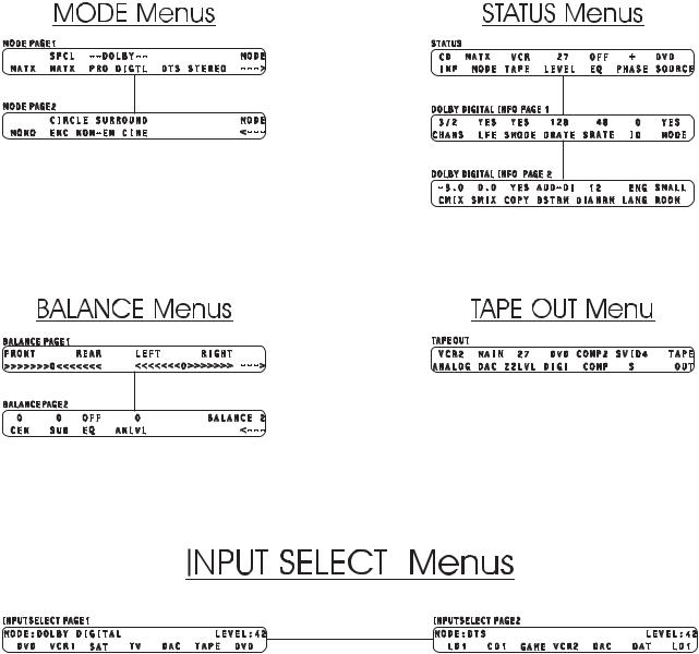
Figure 5 - Mode, Status, Tape Out Menus and Input Select Menus and Pages .................................................................. |
8 |
Figure 6 - Setup Menus and Pages...................................................................................................................................... |
9 |
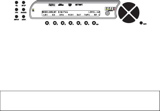
Figure 7 - Front Panel Display of the current INPUT SELECT page.................................................................................. |
11 |
Figure 8 - Front Panel Display of the SETUP/INP/SOURCE/AUD page ............................................................................ |
12 |
Figure 9 - Front Panel Display of the MODE Page 1 Menu................................................................................................ |
13 |
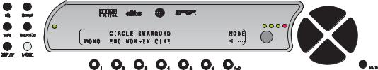
Figure 10 - Front Panel Display of the MODE Page 2 Menu.............................................................................................. |
14 |
Figure 11 - Front Panel Display of the TAPE OUT Menu................................................................................................... |
15 |
Figure 12 - Front Panel Display of the SETUP Page 1 Menu ............................................................................................ |
17 |
Figure 13 - Front Panel Display of the SETUP/Enter Password Display............................................................................ |
17 |
Figure 14 - Front Panel Display of the SETUP/REMPWR Sub Menu ................................................................................ |
18 |
Figure 15 - Front Panel Display of the SETUP/JACKS Sub Menu..................................................................................... |
18 |
Figure 16 - Front Panel Display of the SETUP/ANLG LVLS Sub Menu ............................................................................. |
19 |
Figure 17 - Front Panel Display of the SETUP Page 2 Menu ............................................................................................ |
19 |
Figure 18 - Front Panel Display of the SETUP Page 2/RS232 Sub Menu ......................................................................... |
20 |
Figure 19 - Front Panel Display of the SETUP/INP Page 1 Sub Menu .............................................................................. |
21 |
Figure 20 - Menu Map of SETUP/INP Page 1/CONFIG..................................................................................................... |
21 |
Figure 21 - Front Panel Display of the SETUP/INP/CONFIG Sub Menu............................................................................ |
21 |
Figure 22 - Front Panel Display of the SETUP/INP/CONFIG/SUB CONFIG Sub Menu .................................................... |
22 |
Figure 23 - Menu Map of SETUP/INP Page 1/CONFIG/LT/RT.......................................................................................... |
24 |
Figure 24 - Front Panel Display of the SETUP/INP/CONFIG/LT/RT Sub Menu................................................................. |
24 |
Figure 25 - Front Panel Display of the SETUP/INP/CONFIG/LT/RT/φPERF Sub Menu .................................................... |
25 |
Figure 26 - Front Panel Display of the SETUP/INP/CONFIG/LT/RT/Link-R Sub Menu ..................................................... |
25 |
Figure 27 - Front Panel Display of the SETUP/INP/CONFIG/LT/RT/BWORTH Sub Menu................................................ |
25 |
Figure 28 - Front Panel Display of the SETUP/INP/CONFIG/CENTER Sub Menu............................................................ |
26 |
Figure 29 - Front Panel Display of the SETUP/INP/CONFIG/SURRND Sub Menu ........................................................... |
27 |
Figure 30 - Front Panel Display of the SETUP/INP/LVLS Sub Menu................................................................................. |
27 |
Figure 31 - Front Panel Display of the SETUP/INP/DLYS Sub Menu ................................................................................ |
28 |
Figure 32 - Rear Delay Settings......................................................................................................................................... |
28 |
Figure 33 - Menu Map of SETUP/INP Page 2.................................................................................................................... |
29 |
Figure 34 - Front Panel Display of the SETUP/INP Page 2 Sub Menu .............................................................................. |
29 |
Figure 35 - Front Panel Display of the SETUP/INP Page 2/SOURCE/AUD Sub Menu ..................................................... |
30 |
Figure 36 - Front Panel Display of the SETUP/INP Page 2/DOLBY DIGITAL Page 1 Sub Menu...................................... |
31 |
Figure 37 - Front Panel Display of the SETUP/INP Page 2/DOLBY DIGITAL Page 2 Sub Menu...................................... |
32 |
Figure 38 - Front Panel Display of the SETUP/INP Page 2/DTS Sub Menu ...................................................................... |
33 |
Figure 39 - Front Panel Display of the SETUP/INP Page 2/CIRCLE SURRND Sub Menu................................................ |
33 |
Figure 40 - Menu Map of SETUP/INP Page 3.................................................................................................................... |
34 |
Figure 41 - Front Panel Display of the SETUP/INP Page 3 Sub Menu .............................................................................. |
34 |
Figure 42 - Front Panel Display of the SETUP/INP Page 3/OSD Sub Menu ..................................................................... |
34 |
Figure 43 - Front Panel Display of the SETUP/INP Page 3/OSD/STATUS Sub Menu ...................................................... |
35 |
Figure 44 - Front Panel Display of the SETUP/INP Page 3/MISC Sub Menu .................................................................... |
35 |
Figure 45 - Front Panel Display of the SETUP/INP Page 3/MACROS Sub Menu.............................................................. |
36 |
Figure 46 - Front Panel Display of the BALANCE Page 1 Menu........................................................................................ |
37 |
Figure 47 - Front Panel Display of the BALANCE Page 2 Menu........................................................................................ |
37 |
Figure 48 - Front Panel Display of the STATUS Display.................................................................................................... |
38 |
Figure 49 - Front Panel Display of the STATUS/Dolby Digital Page 1 Display................................................................... |
38 |
Figure 50 - Front Panel Display of the STATUS/Dolby Digital Page 2 Display................................................................... |
39 |
Figure 51 - Remote Control Layout .................................................................................................................................... |
41 |
Figure 52 - Video Display of the INPUT SELECT Page 1 Menu ........................................................................................ |
42 |
Figure 53 - Video Display of the STATUS Display ............................................................................................................. |
43 |
Figure 54A - Video Display of the First Dolby Digital Status Page ..................................................................................... |
43 |
Figure 54B - Video Display of the Second Dolby Digital Status Page ................................................................................ |
43 |
Figure 55A - Video Display of the MODE Page 1 Menu..................................................................................................... |
44 |
Figure 55B - Video Display of the MODE Page 2 Menu..................................................................................................... |
44 |
Figure 56 - Video Display of the TAPE OUT Menu ............................................................................................................ |
45 |
Figure 57 - Video Display of the SETUP Menu Page 1...................................................................................................... |
46 |
Figure 58 - Video Display of the SETUP/PASSWORD Page............................................................................................. |
46 |
Figure 59 - Video Display of the SETUP/REMOTE POWER Sub Menu ............................................................................ |
47 |
Figure 60 - Video Display of the SETUP/INPUT/JACK NAMES Sub Menu ....................................................................... |
47 |
Figure 61 - Video Display of the SETUP/ANALOG INPUT LEVELS Sub Menu................................................................. |
48 |
Figure 62 - Video Display of the SETUP Page 2 Menu...................................................................................................... |
48 |
viii
Figure 63 - Video Display of the SETUP Page 2/RS232 Sub Menu................................................................................... |
48 |
Figure 64 - Video Display of the SETUP/INPUT Page 1 Sub Menu................................................................................... |
49 |
Figure 65 - Video Display of the SETUP/INPUT Page 1/SPEAKER CONFIGURATION Sub Menu.................................. |
49 |
Figure 66 - Video Display of the SETUP/INPUT Page 1/CONFIG/LEFT/RIGHT CONFIGURATION Sub Menu............... |
49 |
Figure 67 - Video Display of the SETUP/INPUT Page 1/CONFIG/CENTER CONFIGURATION Sub Menu ..................... |
50 |
Figure 68 - Video Display of the SETUP/INPUT Page 1/CONFIG/SURROUND CONFIGURATION Sub Menu ............... |
50 |
Figure 69 - Video Display of the SETUP/INPUT Page 1/CONFIG/SUB CONFIGURATION Sub Menu ............................ |
51 |
Figure 70 - Video Display of the SETUP/INPUT Page 1/LEVELS Sub Menu .................................................................... |
52 |
Figure 71 - Video Display of the SETUP/INPUT Page 1/DELAYS Sub Menu.................................................................... |
52 |
Figure 72 - Video Display of the SETUP/INPUT Page 2 Sub Menu................................................................................... |
53 |
Figure 73 - Video Display of the SETUP/INPUT Page 2/DOLBY DIGITAL Page 1 Sub Menu .......................................... |
54 |
Figure 74 - Video Display of the SETUP/INPUT Page 2/DOLBY DIGITAL Page 2 Sub Menu .......................................... |
55 |
Figure 75 - Video Display of the SETUP/INPUT Page 2/DTS Sub Menu........................................................................... |
55 |
Figure 76 - Video Display of the SETUP/INPUT Page 2/CIRCLE SURROUND Sub Menu ............................................... |
56 |
Figure 77 - Video Display of the SETUP/INPUT Page 3 Sub Menu................................................................................... |
56 |
Figure 78 - Video Display of the SETUP/INPUT Page 3/ON-SCREEN DISPLAY Sub Menu ............................................ |
57 |
Figure 79 - Video Display of the SETUP/INPUT Page 3/OSD/STATUS SETUP Sub Menu.............................................. |
57 |
Figure 80 - Video Display of the SETUP/INPUT Page 3/MISCELLANEOUS Sub Menu ................................................... |
58 |
Figure 81 - Video Display of the SETUP/INPUT Page 3/MACROS Sub Menu .................................................................. |
59 |
Figure 82A - Video Display of the BALANCE Page 1 Menu............................................................................................... |
60 |
Figure 82B - Video Display of the BALANCE Page 2 Menu............................................................................................... |
60 |
Figure 83 - Examples of Typical Input and Output Connections ........................................................................................ |
63 |
Figure 84 - Recommended Speaker Placement for Six Channel Configuration................................................................. |
64 |
Figure 85 - Examples of Typical Input and Output Connections Using Analog and Digital out Board................................ |
65 |
List of Tables |
|
Table 1 - Glossary of Terms and Abbreviations ................................................................................................. |
3 |
Table 2 - Available configuration settings for front L/R speaker Phase Perfect crossover.............................. |
25 |
Table 3 - Available configuration settings for front L/R speaker Linkwitz-Riley crossover............................... |
25 |
Table 4 - Available configuration settings for front L/R speaker Butterworth crossover. ................................. |
26 |
Table 5 - Source to Output Routing for Speaker Level Configuration.............................................................. |
27 |
ix
INTRODUCTION
Welcome to a new world of possibilities. Casa Nova is by far the most advanced surround sound processor/home theater controller available today. It offers the advantages of Theta’s legendary mastery in digital signal processing and sound quality unapproachable by any other equipment.
Getting to know your Casa Nova
Despite Casa Nova’s great technical sophistication, we believe in making it as easy as possible for you to use. We think you’ll enjoy the intuitive way the Casa Nova works. Rather than offer a frustrating bewilderment of little used functions in constant view, vying for your attention, Casa Nova is structured systematically by function.
The “user interface” is based on simple logic. For example, when a function button is pressed, you can make changes within its menu(s) and press the same function button again to exit that function. (The same button that got you in gets you back out).
This Casa Nova has been put through a rigorous and unique testing procedure that insures that it will last for many years with minimal service requirements. This procedure includes the following:
•All assembled circuit boards are given a thorough visual inspection and are then tested in a benchreference Casa Nova.
•The tested assembled circuit boards are then installed in a new Casa Nova and the whole unit is tested for every function and parameter.
•The unit is put on a burn-in torture rack for 100 hours to test for any possible component failures.
•The Casa Nova is tested on an audio analyzer for all pertinent parameters.
•The Casa Nova is put through a final bench test wherein every possible feature, mode and parameter is checked.
•The unit has all remaining chassis components installed and then undergoes a complete visual inspection, which assures that all Casa Nova’s meet visual specifications.
•The unit is then put through a critical listening test.
Burn In Time
This unit has a break in period of about 1 week during which continuous improvement in sound quality will be observed. It is recommended that music be played continuously through the unit during this time to expedite the break in period.
1
IMPORTANT NOTICE
I.Due to the computer-based circuitry used in Theta products, it is imperative that the Casa Nova be connected to a ground via its three wire AC power cord. It is important that the AC power outlet, which the Casa Nova is plugged into, is actually grounded. Failure to do so will severely compromise the performance, reliability and safety of use of the Casa Nova.
II.It is also important to prevent contact with static electricity when connecting other components and cables to the Casa Nova. When connecting cables, simply place one hand on top of the Casa Nova and then grasp the metal “barrel” of the cable with the other hand and plug (unplug) the cable into (from) the appropriate jack on the Casa Nova.
III.The Casa Nova, as with all electronic equipment, is susceptible to static discharges. Resetting the unit may be required if anomalies occur after receiving a static discharge. In this case, put the unit in standby and turn off the rear panel power switch for 2 minutes, then turn it on again.
IV. |
Ventilation is an important issue when placing the Casa Nova in a system. Make certain that the |
|
Casa Nova is placed in a well-ventilated area or rack unit. |
V.Please take note that some powerline conditioners defeat the AC power ground on their outlets. If the intention is to plug the Casa Nova into a line conditioner, check with your dealer to make certain that the particular conditioner that is intended for use DOES NOT DEFEAT THE AC GROUND on its AC outlets.
VI. |
DO NOT remove any cover panels from the Casa Nova, as there are no user serviceable |
|
components inside. Refer servicing and updating to qualified service personnel only. |
VII. |
Should the Casa Nova need to be reset, it must be put in standby first via the front panel power |
|
button. Then the rear panel power switch is to be turned off for at least 2 minutes to allow the video |
|
circuitry to reset. |
VIII. |
The Casa Nova can be susceptible to excessive RF. Shorting plugs in all unused inputs will improve |
|
the sound quality and may reduce the susceptibility to RF induced anomalies. |
Reference Manual Conventions
For clarity purposes, references to buttons, LED’s and display parameters will be shown in bold capital letters.
All functions to be performed from, and in reference to the front panel of the Casa Nova will be found in the front section of this manual, whereas all functions to be performed using the hand held remote and/or viewed on a video monitor will be found in the back, or last part of this manual.
2
Glossary of Terms and Abbreviations
TERM |
DEFINITION |
AES/EBU (Audio Engineering Society) / |
A three wire balanced digital audio standard. This |
(European Broadcasters Union) |
interface uses a 3-pin XLR type connector and |
|
allows for data communication between digital audio |
|
equipment. |
Analog-to-Digital Converter |
A device that converts analog signals into a digital |
|
format. Once encoded, all audio is stored or |
|
processed as a series of numbers rather than as the |
|
audio itself. |
Balanced Audio Signals |
Signals that are carried on three-conductor cables, |
|
with two of the conductors carrying the same signal |
|
180° out of phase and the third as ground. |
|
Balanced connections usually cost more than |
|
unbalanced connections, but are less susceptible to |
|
picking up hum and prevent interference with low- |
|
level signals. |
dB |
Decibel, a relative unit of loudness. |
Dolby 3 Stereo |
The Dolby 3 Stereo mode reproduces sound using |
|
only the 3 front channels, and is intended to be used |
|
either before surround speakers are installed, or for |
|
programs that might benefit from deriving a center |
|
channel output, but where the quality of the surround |
|
output is unsatisfactory. |
Digital-to-Analog Converter |
A device that converts digital signals into an analog |
|
format. |
Hz (Hertz) |
A unit of frequency. |
IR |
Infrared. A method of wireless transmission of data. |
LFE |
Low Frequency Effect. Commonly a discrete audio |
|
track designated for a sub woofer. |
mS |
milliSecond, or 1\1000 of a second. |
Oversampling |
The process of taking more samples than is required |
|
in order to more accurately reconstruct a digitized |
|
signal for playback in the analog domain. |
Phantom Center Mode |
The Phantom setting for the center speaker redirects |
|
the center channel signal equally to the front left and |
|
right outputs, thus creating an illusion of a center |
|
speaker. This mode is intended to be used when no |
|
center speaker is present. |
Phantom Surround Mode |
The Phantom setting for the surround speakers is |
|
intended to be used when no surround speakers are |
|
present in the system. With this setting active, the |
|
surround information is added to the front channels. |
|
If the current mode is Dolby Pro Logic, the Casa |
|
Nova will automatically decode in Dolby 3 Stereo. |
Sampling Rate |
The rate at which an analog (real world) signal is |
|
converted into digital numeric values. |
S/PDIF Interface (Sony/Phillips Digital |
A digital audio interconnection standard, developed |
Interface format) |
jointly by Sony and Phillips. |
TRS |
Tip, Ring, Sleeve. Names of the 3 connecting |
|
elements of a stereo phono jack or plug. |
Unbalanced Audio Signals (AKA single-ended) |
Signals that are carried on two-conductor cables, |
|
one “hot”, or signal, and one ground. |
Xover |
Abbreviation for the word ‘Crossover’. |
Table 1 - Glossary of Terms and Abbreviations
3

Casa Nova Block Diagram - Input Processing Sections
Figure 1 - Block Diagram of Input Processing Sections
4
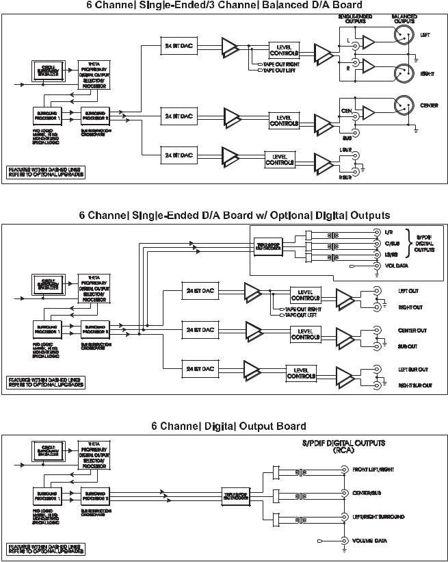
Casa Nova Block Diagram - DAC and Analog Out Sections
Figure 2 - Block Diagram of DAC and Analog Outputs
5
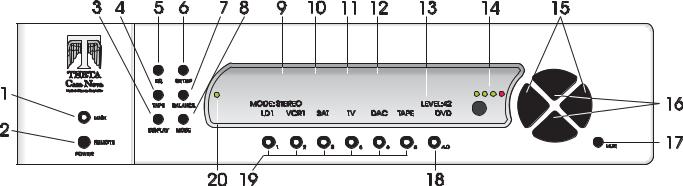
Front Panel Layout
Figure 3 - Front Panel Layout
1.MAIN button. After the rear panel MAIN POWER switch is turned on press the front panel MAIN button to exit the standby mode. The LCD will display the last accessed INPUT SELECT page. Pressing this button again will place the Casa Nova into standby mode and the LED in the front panel MAIN button will light. Remote Power Jacks assigned to this button will activate.
2.REMOTE button. Activates/deactivates the REMOTE POWER jack(s) on the rear panel that are assigned to it.
3.DISPLAY button. Temporarily overrides the LCD brightness display setting in the SETUP/INPUT page 3/MISC sub menu
4.TAPE button. Used for routing audio and video INPUT signals to the TAPE OUT and ZONE 2 jacks.
5.EQ button. Accesses the optional EQ setup menu.
6.SETUP button. Used for setting speaker configurations/levels/delays, analog input levels, naming inputs, setting the display & remote power jack time-out delays, selecting between NTSC and PAL video sources, accessing additional surround parameters, and all other SETUP functions.
7.BALANCE button. Sets temporary balance and level configurations, shelf EQ, and analog input levels to compensate for different program characteristics.
8.MODE button. Activates the MODE select menus for the currently selected input.
9.Dolby Digital indicator. Lights when Dolby Digital is installed. It will go out when the display is turned off.
10.DTS indicator. Lights when the DTS feature is installed. It will go out when the display is turned off.
11.Circle Surround indicator. Lights when the Circle Surround feature is installed. It will go out when the display is turned off.
12.Spatializer indicator. Lights when the Spatializer feature is installed. It will go out when the display is turned off.
13.40 character by 2 row amber back lit liquid crystal display (LCD).
14.ANALOG LEVEL display. Shows input level, in dB, of currently selected analog input.
15.LEVEL LEFT and RIGHT buttons. Shifts audio balance to the left and right when the BALANCE function is selected, adjusts master volume within sub menus when LEVEL UP/DOWN are not available, used to toggle between the 2 Input Select pages, shifts to next character when naming input jacks and input select buttons.
16.LEVEL UP and DOWN buttons. Increases/decreases master volume. Also used to increment/decrement values in most edit modes.
17.MUTE button. Mutes/unmutes all audio outputs with the exception of the TAPE OUT and ZONE 2 jacks.
18.A-D button. Sequences through input jacks mapped (assigned) to the active INPUT SELECT button.
19.Buttons 1 through 6. Used to select the desired input on INPUT SELECT pages, or parameter to change when in a sub menu. The LED in the button lights when the button is pressed. These buttons are referred to as the
INPUT SELECT buttons.
20.LOCK light. Lights when a digital source is detected on a selected input.
6
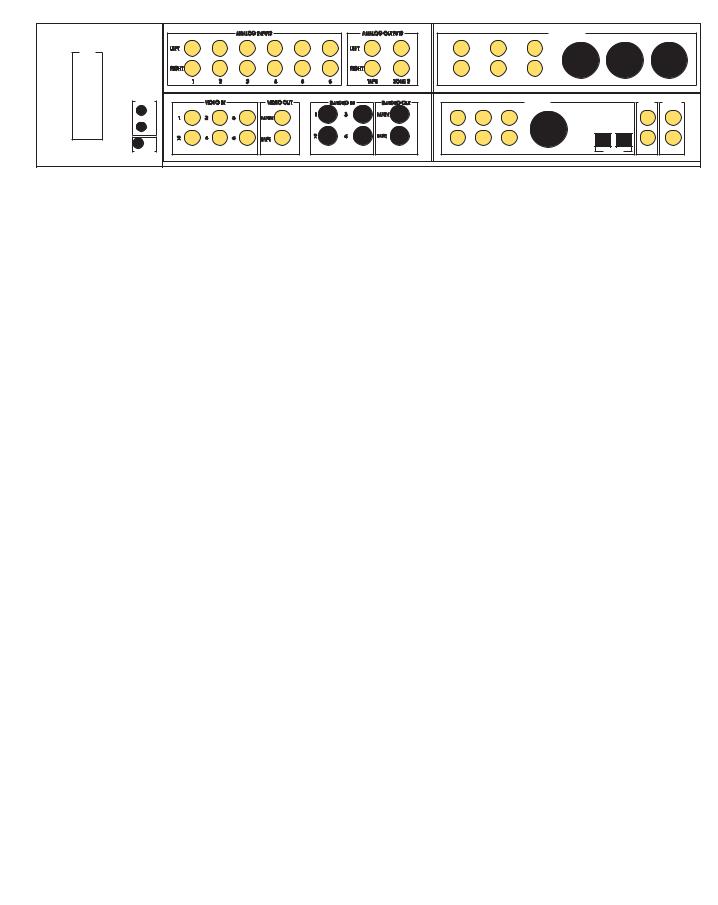
Rear Panel Layout
Figure 4 - Rear Panel Layout
1.AC Power connector: 3 wire, IEC 320 connector with an EMI filter.
2.RJ45 RS232 connector.
3.DB9 RS232 connector.
4.Main Power Switch. Master power switch. Disconnects AC to all circuits. It is recommended that this be left ON at all times during regular use with the exception of whenever cables are connected/disconnected or when the unit is not going to be used for an extended period of time.
5.Remote Extender jack. An externally mounted (remote) Infrared (IR) receiver plugs into this miniature stereo phone jack. Please refer to Appendix C for technical details.
6.Remote Power 1 and 2 jacks. Programmable to be individually activated/deactivated when the MAIN and/or REMOTE buttons on the front panel or remote are pressed/pressed again. They can output a 12V pulse (variable duration) or 12VDC. The output trigger can be delayed up to 255 seconds.
7.Analog Input card. Six stereo RCA inputs are provided for any line level analog output device such as VCR’s, laserdisc, CD and DAT players, phono preamplifiers, external D/A converters, tape decks, AM/FM tuners, etc. There is one pair of analog tape outs for recording purposes and one pair to route to another area (Zone 2). The Zone 2 output level is controlled separately from the main analog output levels.
8.Output card (Balanced and single-ended). This configuration (Balanced analog outputs for Front Left/Right and Center, single-ended (RCA) analog output jacks for Front Left/Right, Center, Sub, Left & Right Surrounds) is the standard option for the output card. (Shown in figure 4, above). The optional Circle Surround, or Circle Surround/Spatializer card mounts on this board.
As a different option for this board, it can be configured to have 6 single-ended (RCA) analog outputs (Front Left/Right, Center, Sub, Left & Right Surrounds) and 6 channels (3 digital pairs) of S/PDIF digital outputs along with a digital volume data output (RCA) to control the output levels of a Theta external volume control unit.
Lastly, this card can be configured as a digital out board only, with S/PDIF digital outputs, for use with external D/A converters. A 2, 4 or 6 channel External Volume Control unit can be used to allow the Casa Nova to control the output volume of the external DACs.
9.Video card. This optional card, necessary for on-screen display, provides six composite RCA inputs that can be switched with any audio inputs and fed to the main video output. Four S-Video inputs, also mappable, provide the same functionality as the composite inputs, except in the S-Video format. Video inputs are routed to the video tape output jack through the TAPE OUT button. Only S-Video input signals can be present at the S-Video Main and/or Tape outputs.
10.Digital Input card. Six Coaxial (RCA), 1 AES/EBU (balanced XLR) and two TosLink inputs are provided for digital audio signals in the S/PDIF format at 32K, 44.1K, 48K, 88.2K and 96KHz sampling rates. Optionally, two Dolby Digital (AC3-RF) jacks and the AC-3 RF demodulator card mount on this card. There is one open space provided for an optional AT&T or Theta Single Mode Laserlinque optical input module. There are two RCA digital Tape Out connectors on this card, the source of which can be selected in the TAPE OUT menu.
Note: The 4 rear panel cards shown in the picture above can be in any position.
7
Menu Maps
Function Menus and Pages
Input Select Pages
Figure 5 - Mode, Status, Tape Out Menus and Input Select Menus and Pages
8

Setup Menus and Pages
Figure 6 - Setup Menus and Pages
9

Introduction to the User interface
WARNING !! : PLEASE READ FIRST!
In the SETUP page 1 menu, the PW button allows the user to password protect the entire SETUP function. In the SETUP/INPUT page 2 sub menu, the PW button allows the user to password protect the currently selected input. When either PW button is selected, a prompt will be displayed asking the user if they are sure they want to change the current password (YES or NO). If YES is selected, the current password will be displayed above the PW button, prompting the end-user to change the current password. The password does not have to be changed at this point, the same numbers that are currently displayed can be entered, using buttons 1-6 and/or A-D. Pressing A-D enters a zero. A password containing at least one zero is null, meaning no password. Therefore, to remove a password, press A-D at least once.
Please note that there are no passwords programmed into the Casa Nova when it is initially shipped.
PLEASE REMEMBER and/or WRITE DOWN YOUR PASSWORD! If it is forgotten, all access to password protected areas will be denied! There is no other over ride to this feature.
The menu system within the Casa Nova consists of 1 to 3 layers, with the exception of the SETUP menu. Some menus have multiple pages, which can be accessed simply by pressing the A/D button, with the exception of the INPUT SELECT menu which uses the LEFT/RIGHT buttons. When a menu has additional pages associated with it, a right or left arrow will be displayed in the bottom right corner of the LCD. Please refer to figures 5 and 6 for an overall view of all menus, sub menus and menu pages.
The SETUP menu contains a number of sub menus, organized by setup function. Since many configuration parameters can be stored for each INPUT SELECT button (by input), they are accessed in one of the 3
SETUP/INPUT sub menus.
Once a parameter is selected for editing, pressing the LEVEL UP/DOWN buttons edits the parameter value, storing it at the same time. On any page, if the LEVEL UP/DOWN buttons are not used for editing a parameter value, they will adjust the master volume. Where the LEVEL UP/DOWN buttons are used for editing a parameter value, the LEVEL LEFT/RIGHT buttons will adjust the master volume, with the exception of the TAPE OUT menu page, the first BALANCE page and the pages where input select buttons and input jacks are named.
The function buttons are defined as the EQ, SETUP, TAPE, BALANCE, and MODE buttons. To exit a function the same function button can be pressed multiple times to exit, or another function button can be pressed at any time.
Before you begin
With all input options installed in a Casa Nova, there are 28 input jacks: 6 stereo analog audio, 12 digital audio, 6 composite video and 4 S-video. Each jack can be named. It is recommended to first name each input jack that is to be used. (SETUP/JACKS)
Each INPUT SELECT button can have up to 6 audio, 6 composite and 6 S-video jacks mapped, or assigned to it. Input jacks should be mapped to INPUT SELECT buttons after the applicable jacks are named. The INPUT SELECT button should also be named. There are a total of 12 INPUT SELECTs on two pages. Pressing the LEVEL LEFT/RIGHT buttons will toggle between these two pages of 6 inputs each.
When editing parameters for a given INPUT, the user must press the applicable INPUT button in the input select page, then press SETUP and INPUT, then navigate to the menu containing the desired parameter to change.
Note: The order in which input jacks are assigned to an INPUT SELECT button determines the search order. Please refer to page 12 for additional information on source assignment (search order). When more than one input jack is assigned to a single INPUT button, toggling the A-D button [when the INPUT SELECT page is active in the LCD] will select the next assigned input jack.
10
FRONT PANEL OPERATIONS
This section describes the functionality of each button on the Casa Nova’s front panel only. For remote functionality descriptions, please refer to the section entitled REMOTE CONTROL OPERATIONS later in this manual. Descriptions for front panel buttons/functionality not covered in this section can be found in the preceding FRONT PANEL LAYOUT section.
Input Select Menus
When the Casa Nova is first powered up via the MAIN POWER switch on the back panel, it will be in the default standby mode. Pressing the MAIN button on the front panel will result in the LCD displaying the start-up routine and then the current INPUT SELECT page, shown in figure 7 below. As this menu appears, the MAIN LED turns off. This display will be on all of the time during normal operation and will change only when one of the function buttons is pressed.
Changing Inputs and Input Select Pages
The INPUT NAMES shown in this figure are for example only and will most likely differ from the user’s set up. There are two INPUT SELECT pages, giving the user a total of 12 inputs. Buttons 1 through 6 are used to select a desired input, or audio/video source. The selected button will illuminate when pressed. When the Casa Nova exits standby mode, the INPUT SELECT page with the last selected input is displayed. Pressing the LEVEL LEFT or RIGHT buttons toggles between the two INPUT SELECT pages.
* * *
Figure 7 - Front Panel Display of the current INPUT SELECT page
Pressing the LEVEL UP/DOWN buttons will adjust the master volume for all speakers. A temporary bar graph appears on the LCD and OSD as the master volume is being adjusted. This value ranges from 0 to 73, relative maximum.
Selecting Mapped Input Jacks for the Currently Selected Input
Pressing the A-D button will toggle between the input jacks that are mapped to this INPUT SELECT button. Please refer to page 12 (Search Order) for important, detailed information regarding using the A-D button.
* * *
The MUTE button will toggle the audio between the master volume level and MUTE level* in all speakers each time it is pressed. When the mute feature is enabled, the word LEVEL in the LCD will be replaced with the word MUTED, which will remain displayed until the MUTE button is pressed again. The MUTE feature is active in all menus.
*Note: The factory default value for MUTE is 0, which is to say that when the MUTE button is pressed, the output level of all 6 channels will be completely muted (master volume = 0). The Casa Nova offers a feature in the SETUP/INPUT Page 3/MISC sub menu whereby when the MUTE button is pressed, the Casa Nova will mute to a user defined master volume level. Please refer to page 36 for additional information regarding this feature.
11
Search Order
The Casa Nova’s inputs can support virtually every digital audio data format used in today’s technology. Up to 6 audio input jacks can be mapped to one INPUT SELECT button. These 6 input jacks can be all digital, all analog or any combination of both. In the SETUP/INP Page 2/SOURCE/AUD page, the order in which they are mapped to a given input determines the order each is displayed when the A-D button is pressed. This is called Input Search Order. Figure 8 below shows INPUT SELECT 1 having the CD and DVD input jacks mapped to it, with the CD jack having the highest priority (being in the first position). In this example, there are no other physical input jacks required to be mapped to INPUT SELECT 1, therefore the jack names of 3-6 are blank. Pressing the A-D button while in the INPUT SELECT page, selects either the CD input jack, or the DVD input jack. Pressing the A-D button in the SETUP/INP Page 2/SOURCE/AUD sub menu will access the composite video search order page. In this page, pressing buttons 1-6 will allow the user to assign a composite video input jack (1-6) to correspond to the respective audio search order. In the above example, one would not assign a composite video jack to search order # 1 since the audio search order # 1 is assigned to CD, which is not a video source. If one wanted an unrelated video source to be viewable when listening to CD’s, simply map a video source to composite video search order # 1. Also in the above example, one would normally assign the DVD composite video input to composite video search order
# 2. This will select the correct video jack to correspond to the desired audio jack. In this example, if the video signal were to be carried via an S-video cable, pressing the A-D button once while in the SETUP/INP Page 2/SOURCE/COMP page would reveal the SETUP/INP Page 2/SOURCE/SVID page and the same procedure would apply as with a composite video source.
Figure 8 - Front Panel Display of the SETUP/INP/SOURCE/AUD page
Caution: Please take special care to insert only a digital signal into a digital input jack and an analog signal only into an analog input jack. Damage, not covered under warranty, can occur if an analog signal is applied to a digital input. Additionally, please ensure that a video plug is not inadvertently inserted into a digital audio jack and visa versa, otherwise, the Casa Nova will cease to respond.
12
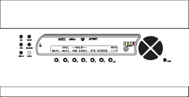
MODE Function
Pressing the MODE button (shaded in figures 9 and 10) once displays the first page of the MODE menu. This page consists of 6 different signal ‘processing’ modes, one of which can be selected and temporarily applied to the currently selected input. A right arrow is displayed in the lower right corner of the LCD indicating that there is another MODE page. Pressing the A-D button once will reveal this second page, consisting of additional modes. In this second page, a left arrow is displayed in the LCD, above the A-D button. This indicates that pressing the A-D button once more will return the user to the first MODE page. Figure 9 shows the first MODE page and figure 10 shows the second.
Note: This entire menu allows the user to audition different modes when possible. It does not store the changed mode. Therefore when a different INPUT SELECT button is pressed, or the Casa Nova is powered down, a MODE that is changed using this function will revert to its default. Since each INPUT SELECT button can have its own MODE, the default mode for that INPUT SELECT is stored/edited in the SETUP/ INPUT menu. Please refer to page 28 (Default Mode) for information on changing and storing the MODE for a given INPUT SELECT button.
* * *
Figure 9 - Front Panel Display of the MODE Page 1 Menu
Press button 1 - 6 to select the desired mode. The corresponding LED within buttons 1 through 6 will illuminate.
Note: If a specific feature such as Dolby Digital or DTS is not installed in the Casa Nova, selecting either in the MODE menu will result in the LCD displaying the following message: OPTION NOT INSTALLED.
The first 6 modes shown in figure 9 are described below.
Simple Matrix (MATX): The signal routed to the center speaker is equal to the left plus right input signals and the signal routed to the surround speakers is equal to left minus right signals. Crossing over any speaker(s) produces a sub channel.
Special Matrix (SPCL MATX): A mode similar to Dolby Pro Logic with more ambience retrieval in the surround speakers.
Dolby Pro Logic (PRO): When PRO is selected, Dolby Pro Logic decoding is implemented.
Dolby Digital (DIGTL): (Optional). When this mode is selected, Dolby Digital decoding is implemented. Please refer to page 31 for additional Dolby Digital setup options, selectable in the second page of the
SETUP/INPUT submenu.
If the Casa Nova detects a Dolby Digital signal on the selected input jack, and the MODE is not set to DOLBY DIGITAL, the Casa Nova will display the following message on both the LCD and video monitor:
**RECEIVING DOLBY DIGITAL SIGNAL**
CHANGING MODE TO DOLBY DIGITAL
and display DOLBY DIGITAL as the current mode. However, this is not stored and therefore approximately 15 seconds after the Casa Nova ceases to receive this signal, the MODE will revert back to the previous mode before detecting the Dolby Digital signal.
DTS: (Optional) Selecting DTS will decode a Digital Theater Systems encoded signal according to the DTS specification which consists of up to 5 plus 1 discrete channels of digital data for a total of 6 separate audio channels.
13
If the Casa Nova detects a DTS signal on the selected input jack, and the MODE is not set to DTS, the Casa Nova will display the following message on both the LCD and video monitor:
**RECEIVING DTS SIGNAL**
CHANGING MODE TO DTS
and display DTS as the current mode. However, this is not stored and therefore approximately 15 seconds after the Casa Nova ceases to receive this signal, the MODE will revert back to the previous mode before detecting the DTS signal. Please refer to page 33 for additional DTS setup options, selectable in the second page of the SETUP/INPUT submenu.
STEREO: Left and Right input signals are sent to the Left and Right front speakers, which if crossed over, will produce a SUB channel.
When the Casa Nova receives a 96K input signal, the following message will appear in the display:
**RECEIVING 96K SIGNAL** CHANGING MODE TO STEREO
And the MODE will be changed to STEREO. A few seconds after the 96K signal is no longer received, the Casa Nova will return back to the stored MODE.
* * *
Figure 10 - Front Panel Display of the MODE Page 2 Menu
Each of the 4 modes shown in figure 10 are described below.
MONO: This mode routes the input signal to the center channel only, however, if the center channel is crossed over, a sub channel will be produced. If the center channel is set to OFF or PHANTM in the SETUP/ INPUT/CONFIG sub menu, the input signal will be routed to the front left and right speakers.
CIRCLE SURROUND: The ENC (Encoded) and NON-EN (Non Encoded) Circle Surround modes are intended for music playback, whereas the CINE mode is intended for Cinematic use. In all 3 Circle Surround modes, the center channel operates dynamically in order to avoid collapsing any stereo imaging that may be present toward the center channel. This works to maintain a wide left/right soundfield in the front channels. All Circle Surround modes provide multi-band left/right steering in the surround channels.
When the source music is Circle encoded, the intended mode is Circle ENC, leaving the NON-EN mode for non Circle encoded music. CINE is a non-encoded mode that is intended to be used for mono, stereo or matrixed film sources.
Circle Surround operates effectively with both encoded and non-encoded material, and allows the processing of the front left/right and center channels as well as full bandwidth of the left and right surrounds. Please refer to page 33 for additional Circle Surround setup options, selectable in the second page of the
SETUP/INPUT submenu.
* * *
After selecting a mode for the current input channel, pressing the MODE button once more returns the Casa Nova to the INPUT SELECT menu. While in the MODE menu, the MASTER VOLUME can be controlled using the LEVEL UP/DOWN buttons.
14
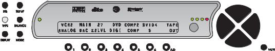
TAPE OUT Function
This feature individually routes input signals to the video, analog, zone 2 and digital audio tape out jacks as well as the ZONE 2 outputs.
Pressing the TAPE OUT button once changes the LCD display to the TAPE OUT menu shown in figure 11. Note: The INPUT NAMES shown in this figure are for example only and will most likely differ from the user’s set up.
* * *
Figure 11 - Front Panel Display of the TAPE OUT Menu
In this menu, pressing button # 1 allows the user to route any audio input jack, analog or digital, to the analog TAPE OUT jacks. The same input jack is also routed to the ZONE 2 output jacks.
Button # 2 allows the user to select whether the signal at the analog TAPE OUT and ZONE 2 jacks will be derived from the main output DACs or the optional tape out DAC, by displaying MAIN or TAPE in the display. If the optional tape out DAC has not been installed, changing this value will result in the following message: OPTION NOT INSTALLED. This setting is only relevant if the analog tape out source is set to a digital input jack. All analog inputs are routed directly to the TAPE OUT jacks, without A/D to D/A conversion.
The ZONE 2 output level can be adjusted independently of the Casa Nova’s master volume via button # 3. The maximum level is 55 and each increment is 1dB. Both the LEVEL UP/DOWN and LEFT/RIGHT buttons adjust this parameter value and in this case, button # 3 does not need to be pressed first.
Button # 4 allows the user to route any digital audio input jack to the digital TAPE OUT jacks.
Button #’s 5 and 6 route composite and S-video inputs to the composite and S-Video TAPE OUT jacks, respectively.
Standard Tape Out Configuration
The following guidelines apply when the tape out circuitry is in its standard configuration, i.e. the optional tape out D/A converter has not been installed.
A source to be recorded (via the analog TAPE OUT jacks) can be selected independently of the source currently being viewed or listened to provided that the input for the source to be recorded is ANALOG.
It is possible to record a digital source in analog only if the source is the same as the input being watched or listened to. If the desired source is 5.1 (DTS/AC-3), it is recommended that both the surrounds and center speakers be set to phantom (PHTM). This mixes those channel’s information into the front left/right channels, thus eliminating lost information from an analog copy.
Optional Upgrade Tape Out Configuration
When the optional D/A converter has been installed onto the Digital Input board, a digital source can be recorded, i.e. sent to the analog TAPE OUT jacks, (and routed to the ZONE 2 outputs) at the same time as a different digital source is being watched or listened to.
* * *
15

To route a signal to the appropriate TAPE OUT jack(s), press the TAPE OUT button and then select a source for the appropriate TAPE OUT (analog/zone 2, digital, composite and/or S-video) by first selecting buttons 1, 4, 5, and/or 6, respectively and using the LEVEL UP/DOWN buttons. A composite video source will only be routed to the composite video TAPE OUT jack and an S-video source can only be routed to the S-video TAPE OUT jack.
Now the routing is completed. Press TAPE OUT again to return the Casa Nova to the current INPUT SELECT page.
CAUTION: It is not advisable to route a 5.1 source (DTS/AC-3) to the optional tape out DAC as this section does not contain Dolby Digital or DTS decoding capabilities. Full scale and potentially damaging noise will be output!
16
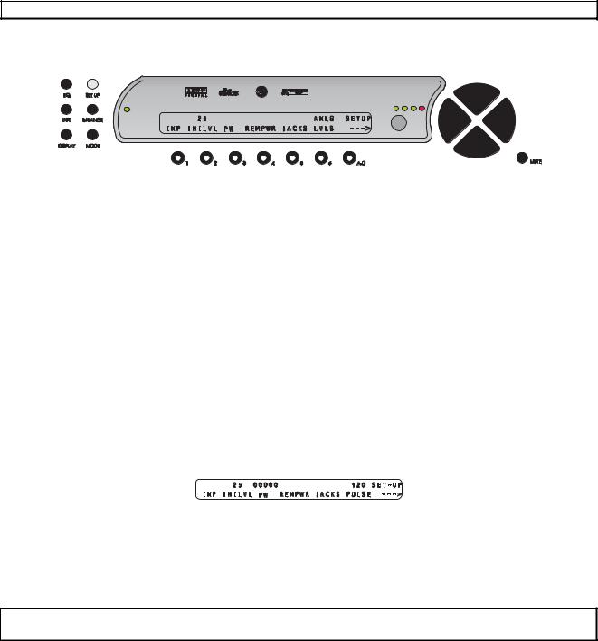
SETUP Function
This function provides access to a series of sub menus that will allow the configuration of the entire system. In this section, each feature of the SETUP menu is discussed in detail along with a diagram of each LCD display.
Note: A complete step-by-step speaker configuration setup guide is located in Appendix D.
Pressing the SETUP button once changes the front panel display to the first page of the SETUP menu, shown in figure 12.
* * *
Figure 12 - Front Panel Display of the SETUP Page 1 Menu
The menu title “SETUP” is displayed in the upper right corner. A right arrow is displayed in the lower right corner of the LCD indicating that there are more setup options to select from on the next page. Pressing the A-D button once will reveal this second page. On the second page the menu title “SETUP” is also displayed in the upper right corner with a left arrow displayed below it. This indicates that pressing the A-D button once more will return the user to the first SETUP page. Figure 12 shows the first SETUP page and figure 17 shows the second.
As indicated in figure 12, button 1 is assigned to features that are stored by input and leads to a series of categorized sub menus via 3 pages. Most pages, menus and all features are detailed further in this section.
Initial Power-On Master Volume
Button 2 allows the user to store an initial master volume setting that the Casa Nova will default to when it comes out of standby.
Setup Button Password
It is possible to password protect the entire SETUP function, or have no password at all. Setting a password for the SETUP button is accessed by pressing button # 3, where the user will be asked “ARE YOU SURE?” Answering “YES” by pressing button # 2 will display the following page:
Figure 13 - Front Panel Display of the SETUP/Assign Password Display
Use buttons 1-6 to assign a password. After each digit is entered, the cursor (flashing in the Onscreen Display (OSD) only, not the LCD) moves one character to the right. If no password is to be used (factory default), press the A-D button five times, which enters all zeros. All zeros, or a zero anywhere in the password translates to no password.
CAUTION: It is imperative that your new password be written down. If it is forgotten, ALL access to the SETUP menu will be permanently denied. Please see the WARNING on page 10.
Remote Power Jacks
The two REMOTE POWER jacks on the rear panel can be programmed to output 12V, either straight DC or as a pulse and each can be activated by either the MAIN or REMOTE power button on the front panel. Press button # 4 to access the REMPWR sub menu shown in figure 14.
17

Figure 14 - Front Panel Display of the SETUP/REMPWR Sub Menu
Button # 1 (1SRCE, or remote power jack 1 source) allows the user to map which front panel button will activate the remote power 1 jack on the rear panel. The options are either the MAIN or REMOTE front panel buttons.
Use button # 2 to indicate whether the output of the remote power jack 1 should be 12VDC (DC) or a 12V pulse (PULSE). The specification sheet for the device connected to the remote power 1 jack should contain information as to which type of signal it requires, and if it is a pulse, the minimum pulse duration.
The output signal of the remote power jack can be delayed after its activating button is pressed. This is useful for sequencing high power components such as amplifiers. Button # 3 allows the user to set this delay time, in seconds.
Buttons 4, 5 and 6 have exactly the same functionality as buttons 1, 2 and 3, except that they apply for the remote power 2 jack on the rear panel.
If the type of output for one or both of the remote power jacks is a 12V pulse, the duration (in milliseconds) of this pulse can be set by the user, using the A-D button.
Press SETUP once to return to the first page of the SETUP menu.
Jack Names
Button # 5 accesses a series of sub menus, which allow the user to name all of the Casa Nova’s input jacks, both audio and video. The JACKS sub menu is shown in figure 15.
Figure 15 - Front Panel Display of the SETUP/JACKS Sub Menu
Pressing button # 1 accesses a sub menu that allows the analog audio input jacks to be named. Button # 2 does the same for the coaxial digital audio input jacks, whereas button # 3 allows the user to name all noncoaxial digital audio input jacks. Buttons # 4 and # 5 lead to sub menus that allow the naming of the composite and S-video jacks, respectively.
Example of editing a jack name:
To edit the name of analog input jack 1, press button # 1 from the menu shown above. This displays the NAME ANALOG sub menu. Then press button # 1 (first analog input jack name). Press the LEVEL UP/DOWN buttons to select the desired LCD character and the LEVEL LEFT/RIGHT to change character positions. Once selected, pressing the DISPLAY button once will clear the current jack name. There is not a blinking cursor in the LCD. The LCD name for all audio input jacks can be up to 6 characters and the video jack names up to 5. Press the A-D button to edit the OSD name. OSD will be displayed above the A- D button in the LCD. ALL OSD names can be up to 15 characters and the current character to be edited will blink.
18

Analog Input Levels
Lastly on this page, button # 6 accesses the ANALOG INPUT LEVELS submenu, shown in figure 16.
Figure 16 - Front Panel Display of the SETUP/ANLG LVLS Sub Menu
This function allows the user to adjust the relative ANALOG input LEVEL for each input source for those modes which require analog to digital conversion. This function does not affect source levels when a digital audio input is selected. The allowable relative range is -23 dB to +14 dB, in 1dB increments.
Note: To obtain the best performance from the analog to digital conversion process, levels should be set so that the loudest passages from the source material cause the -18, -12 and -6 dB ANALOG input LEVEL LEDs on the front panel to light. Setting the input level too high will cause all four LEDs to light, thus clipping the input signal and causing distortion.
Analog output levels may vary considerably for different input sources. Program material from a given input source should not vary as greatly. Therefore the ANALOG input LEVEL for a given source should not have to be adjusted very often. If, however, the input ANALOG LEVEL LEDs are not lit during the loudest passages from an analog source, the user should increase the ANALOG input LEVEL for that source in order to ensure a good signal to noise ratio.
Select the analog input to be adjusted by pressing buttons 1-6 once. Adjust the relative input level using the LEVEL UP/DOWN buttons, then press the SETUP button twice to return to the current INPUT SELECT page.
* * *
Pressing the A-D button shifts to the second page of the SETUP menu, shown in figure 17.
Figure 17 - Front Panel Display of the SETUP Page 2 Menu
Temporary Settings Control
Any changes in the BALANCE menus are, by default, temporary. That is to say that when an INPUT SELECT button is pressed or the Casa Nova is powered down/put into standby, any changes will be reset to zero. This feature has an override, which is set by pressing button # 1 and set to OFF. When this parameter is set to OFF, changing inputs powering down/going into standby will maintain all BALANCE menu settings.
RS232
Press button # 2 to access the RS232 sub menu, if the optional RS232 feature has been installed.
Pressing the A-D button shifts back to the first page of the SETUP menu.
19
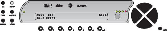
Figure 18 - Front Panel Display of the SETUP Page 2/RS232 Sub Menu
Press button # 1 (BAUD) and use the LEVEL UP/DOWN buttons to select the Baud rate that matches that of the RS232 controller.
The RS232 can be set to automatically send changes to the RS232 port. This can be done by selecting a “Status Level”, which means if any Casa Nova parameter changes, that level's bytes will be sent to the port. This is useful for monitoring master level, input and the like when the user has access to both the Casa Nova and the touch-panel controller, to keep them synchronized.
Button # 2 (ECHOS) [Status] allows the user to enable or disable the output of data to the RS232 port and, if enabled, determine which level, or pre-determined group of bytes it outputs. Setting this value to OFF disables any parameter change information from being output to the RS232 port. If RS232 is installed in a Casa Nova, an addendum will be included with this manual which describes all pertinent RS232 information, including values contained within each Status Level.
If the RS232 option is installed but not being used, ensure that the Echo Status (ECHOS) parameter is set to OFF. Other settings can slow the operation of the Casa Nova.
Pressing the SETUP button twice (if in the RS232 sub menu, once if in SETUP page 2) returns the LCD to the current INPUT SELECT page.
20

SETUP INPUT (Setting up each of the 12 Input Select Buttons)
Setup Input Page 1
All parameters accessed within the SETUP/INP menu are programmable for each of the 12 INPUT SELECT buttons. The first of 3 pages of the SETUP/INP sub menu is shown below, in figure 19.
Figure 19 - Front Panel Display of the SETUP/INP Page 1 Sub Menu
Speaker Configuration
The Speaker Configuration section utilizes the menus shown in figure 20.
Figure 20 - Menu Map of SETUP/INP Page 1/CONFIG
This sub menu (CONFIG) allows the user to configure speakers to reflect the audio system configuration or the listener’s preference, for the available speakers and their respective frequency responses.
All of the speaker configuration parameters are accessed by pressing button # 1 (CONFIG). This leads to a series of sub menus shown that are described next. The first sub menu, SPEAKER CONFIG is shown below, in figure 21.
Figure 21 - Front Panel Display of the SETUP/INP/CONFIG Sub Menu
As indicated in figure 21 above, the front left/right speaker configuration is accessed by pressing button # 1, the center via button # 2, the surrounds with button # 3 and # 4 is for the sub woofer. There are 3 types of crossovers to choose from, which can be selected via button # 5. Before configuring any speakers in the system, it is important to configure the sub woofer, then the crossovers for each speaker. First, determine
21
Loading...