

Theta Digital Casablanca IV Owner's Manual
Effective October 1, 2014 the Analog Input Level display was
deleted from the Casablanca IV.
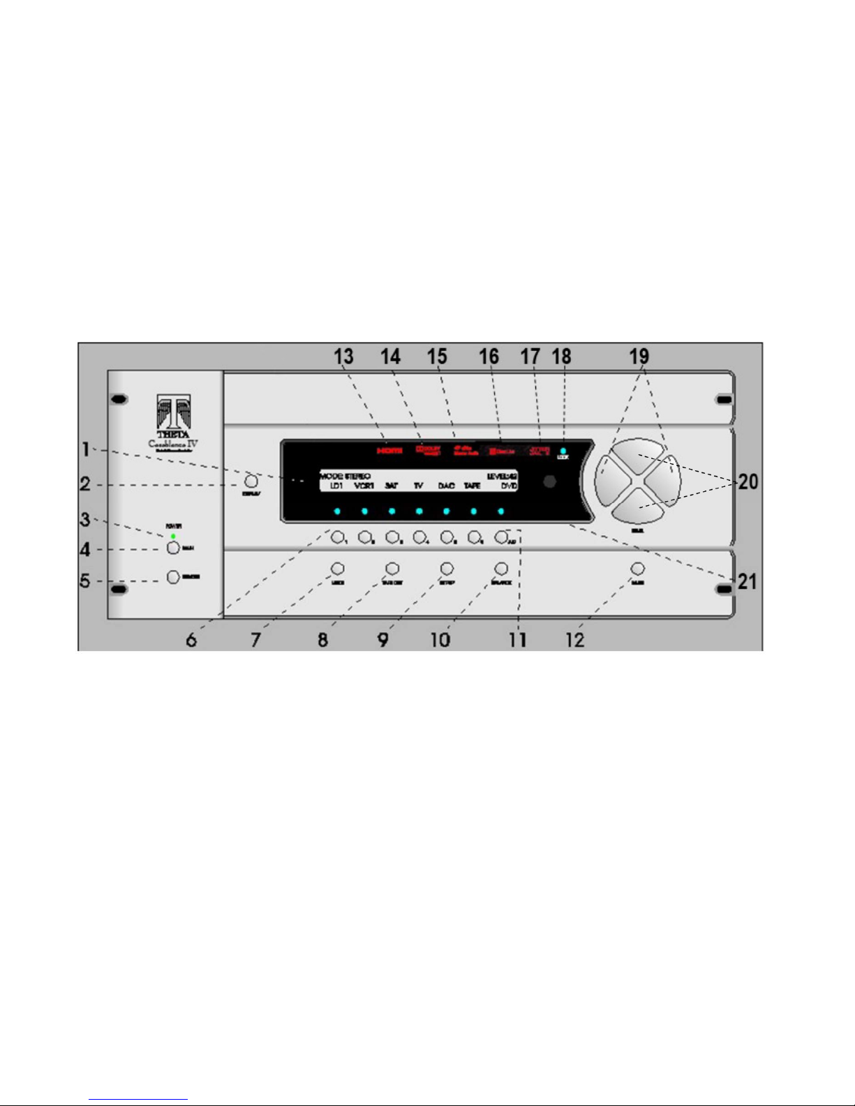
The Revised Front Panel Layout is shown in Figure 6, below.
Figure 6 - Front Panel Layout
13
THETA DIGITAL
Casablanca IV
Owner’s Manual
V 4.02
Digital Done Right
™

PREFACE
You have just acquired the most advanced component for the control and processing of audio and video ever to
have been developed.
IMPORTANT
CONGRATULATIONS
Save all packaging in a dry place away from fire hazards. Your Casablanca IV is a precision electronic instrument
and should be properly packaged any time shipment is made. In the unlikely event that you have to return your
Casablanca IV to the factory for service, or if you send it to us for updating, the original packaging will best protect
the unit from shipping damage.
In order to achieve the fullest flexibility and enjoyment from your Casablanca IV, we at Theta recommend that you
read this manual in full before connecting the unit to your audio/video system.
WARNING
United Stated law prohibits disposition of these commodities to Libya, Laos, North Korea, Cambodia or Cuba
unless otherwise authorized by the United States.
NOTE:
This equipment has been tested and found to comply with the limits for a Class B digital device, pursuant to Part
15 of the FCC rules. These limits are designed to provide reasonable protection against harmful interference in
a residential installation. This equipment generates, uses and can radiate radio frequency energy and, if not
installed and used in accordance with the instructions, may cause harmful interference to radio communications.
However, there is no guarantee that interference will not occur in a particular installation. If this equipment does
cause harmful interference to radio and television reception, which can be determined by turning the equipment
off and on, the user is encouraged to try to correct the interference by one or more of the following measures:
* Reorient or relocate the receiving antenna.
* Increase the separation between equipment and receiver.
* Connect the receiver into an outlet on a circuit different from that which the Casablanca IV is connected to.
Acknowledgments
Casablanca IV is manufactured under license from Dolby Laboratories. “Dolby”, “Pro Logic”, “Dolby TrueHD”
and the double-D symbol are registered trademarks of Dolby Laboratories.
Casablanca IV is manufactured under license from Digital Theater Systems, Inc. U.S. Pat. No's. 5,451,942;
5,956,674; 5,974,380; 5,978,762; 6,226,616; 6,487,535 and other U.S. and world-wide patents issued and
pending. "DTS", "DTS-ES", "DTS-ES", "Neo:6", "DTS 96/24" and “DTS Master Audio” are trademarks of Digital
Theater Systems, Inc. Copyright 1996, 2003 Digital Theater Systems, Inc. All Rights Reserved.
© 2000-14 Theta Digital. All rights reserved.
This manual is also available for download as a PDF file at Theta Digital’s website. http://www.thetadigital.com
No part of this publication may be reproduced or transmitted in any form or by any means, electronic or
mechanical, for any purpose, without the express written permission of Theta Digital.
ii
The lightning flash with arrowhead symbol, within an equilateral
triangle, is intended to alert the user to the presence of uninsulated
“dangerous voltage” within the product’s enclosure that may be of
significant magnitude to constitute a risk of electric shock to persons.
The exclamation point within an equilateral triangle is intended to alert
the user to the presence of important operating and maintenance
(servicing) instructions in the literature accompanying the product.
WARNING
TO REDUCE THE RISK OF FIRE OR ELECTRIC SHOCK,
DO NOT EXPOSE THIS PRODUCT TO RAIN OR MOISTURE
CAUTION: TO PREVENT ELECTRIC SHOCK, DO NOT USE THE (POLARIZED) PLUG WITH AN
EXTENSION CORD, RECEPTACLE OR OTHER OUTLET UNLESS THE BLADES CAN BE FULLY
INSERTED TO PREVENT BLADE EXPOSURE.
iii

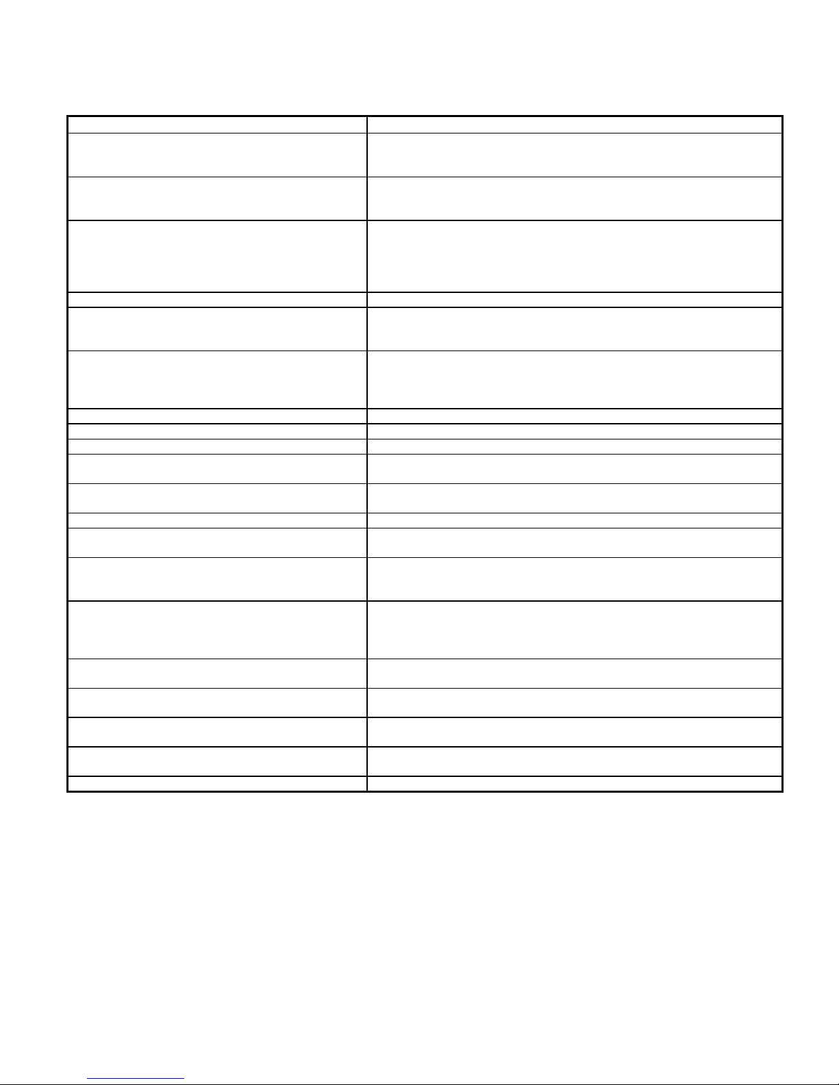
Casablanca IV Identification Record
This information is for your records and for future identification of the Casablanca IV. Please take a moment
to fill out all pertinent data now, and as upgrades and/or options are installed. Whenever upgrades, inquiries
and/or changes are requested, the serial number will be required.
SERIAL NUMBER
DATE PURCHASED
DEALER’S NAME
DEALER’S ADDRESS/PHONE
INSTALLED CARDS/OPTIONS
(Date of installation)
(Date of installation)
(Date of installation)
(Date of installation)
(Date of installation)
(Date of installation)
(Date of installation)
(Date of installation)
(Date of installation)
(Date of installation)
(Date of installation)
iv

SAFETY PRECAUTIONS
Please carefully read each item of the operating instructions and safety precautions before using this product.
Use extra care to follow the warnings written on the product itself and/or in the operating instructions. Keep
the operating instructions and safety precautions for future reference.
CAUTION: TO REDUCE THE RISK OF ELECTRICAL SHOCK, DO NOT REMOVE ANY OF THE COVER
PANELS.
NO USER-SERVICEABLE PARTS INSIDE. REFER ALL SERVICING TO QUALIFIED SERVICE
PERSONNEL ONLY.
TO PREVENT FIRE OR SHOCK HAZARD, DO NOT ALLOW LIQUIDS TO SPILL OR OBJECTS TO FALL
INTO ANY OPENINGS OF THE PRODUCT.
THIS UNIT IS SUPPLIED WITH A 3 PIN GROUNDED AC PLUG. ALWAYS INSERT THE AC PLUG INTO A
GROUNDED OUTLET. DO NOT REMOVE THE GROUND PIN OR DISABLE THE GROUND FOR ANY
PURPOSE.
BEFORE MAKING ANY CONNECTIONS TO THE CASABLANCA IV, FIRST TURN OFF THE POWER AND
THEN DISCONNECT THE AC POWER CORD.
WHEN INSTALLING THE CASABLANCA IV IN YOUR SYSTEM, MAKE CERTAIN TO ALLOW A MINIMUM
OF 3 INCHS OF VENTILATION ON EACH SIDE OF THE UNIT. ALSO ALLOW AT LEAST 4 INCHS OF
VENTILATION SPACE ABOVE THE UNIT. IMPROPER VENTILATION OF THE UNIT MAY CAUSE
OVERHEATING, WHICH MAY DAMAGE THE UNIT AND CAUSE A FIRE. PLACE THE UNIT ON A SOLID
SURFACE ONLY. I.E. NOT ON CARPET, ETC.
DO NOT PLACE THE CASABLANCA IV NEAR HEAT SOURCES SUCH AS DIRECT SUNLIGHT, STOVES,
HEAT REGISTERS, RADIATORS OR OTHER HEAT PRODUCING EQUIPMENT.
TO PREVENT DAMAGE TO THE ANALOG OUTPUT CIRCUITRY, BE CERTAIN NOT TO SHORT THE
OUTPUT SIGNAL PIN(S) TO GROUND. ENSURE THAT YOUR AUDIO OUTPUT CABLES DO NOT HAVE
ANY INTERNAL SHORTS BEFORE CONNECTING THEM TO THE CASABLANCA IV.
IF REPLACEMENT OF THE AC LINE FUSE BECOMES NECESSARY, REPLACE ONLY WITH SAME
VALUE AND TYPE OF FUSE. NEVER BYPASS THE FUSE.
IF THE AC CORD BECOMES DAMAGED, DO NOT USE IT. IMMEDIATELY REPLACE IT WITH A NEW
ONE OF THE SAME OR BETTER RATING.
AFTER MARKET and THIRD PARTY MODIFICATIONS
Please note that any aftermarket and/or third party modifications will void the warranty. In the case of changing
the feet on a unit, in order to prevent any damage (which will also not be covered under warranty), please
verify that the screws being used to secure non Casablanca IV feet do not screw any deeper into the chassis
than the original ones. The original screw is 10-32 by 3/8 and goes into the chassis 1/5 inch.
v

TableofContents
PREFACE ........................................................................................................................................................... ii
WARNING ....................................................................................................................................................... iii
Casablanca IV Identification Record .............................................................................................................. iv
SAFETY PRECAUTIONS ............................................................................................................................... v
AFTER MARKET and THIRD PARTY MODIFICATIONS ........................................................................... v
INTRODUCTION ................................................................................................................................................ 7
Getting to know your Casablanca IV .............................................................................................................. 7
Burn In Time ................................................................................................................................................ 7
IMPORTANT NOTICE .................................................................................................................................... 8
Reference Manual Conventions ..................................................................................................................... 8
Glossary of Terms and Abbreviations ............................................................................................................. 9
Casablanca IV Block Diagram - Input Processing Sections ......................................................................... 10
Front Panel Layout ........................................................................................................................................ 13
Rear Panel Layout ........................................................................................................................................ 14
Introduction to the User interface .................................................................................................................. 20
Before you begin ....................................................................................................................................... 20
Casablanca IV Default Settings .................................................................................................................... 22
Overall Setup Procedure Flowchart .............................................................................................................. 23
................................................................................................................................................................... 23
Figure 12: Casablanca IV Basic Set-up Flow Chart ................................................................................. 23
Step by Step Speaker Configuration ......................................................................................................... 24
Speaker Levels .......................................................................................................................................... 24
Speaker Delays ......................................................................................................................................... 24
Dolby Digital, DTS Setup ........................................................................................................................... 28
Remaining Setup ....................................................................................................................................... 28
FRONT PANEL OPERATIONS ........................................................................................................................ 42
Input Select Menus ....................................................................................................................................... 42
Changing Inputs and Input Select Pages .................................................................................................. 42
Selecting Mapped Input Jacks for the Currently Selected Input ............................................................... 42
Search Order ............................................................................................................................................. 44
MODE Function ............................................................................................................................................ 45
TAPE OUT Function ..................................................................................................................................... 48
SETUP Function ........................................................................................................................................... 49
DAC Configuration .................................................................................................................................... 49
SETUP INPUT (Settings specific to each of the 12 Input Select Buttons) ................................................ 50
Setup Global .............................................................................................................................................. 69
Macros ....................................................................................................................................................... 74
BALANCE Function ...................................................................................................................................... 76
Front/Rear and Left/Right Balance ............................................................................................................ 76
Center and Sub Balance ........................................................................................................................... 76
Analog Input Level Override ...................................................................................................................... 76
STATUS Function ......................................................................................................................................... 77
REMOTE CONTROL OPERATIONS ............................................................................................................... 81
Input Select Menus ....................................................................................................................................... 81
Changing Inputs and Input Select Pages .................................................................................................. 81
Selecting Mapped Input Jacks for the Currently Selected Input ............................................................... 81
Mute ........................................................................................................................................................... 81
Display ....................................................................................................................................................... 81
Global Phase ............................................................................................................................................. 81
STATUS Display ........................................................................................................................................... 82
MODE Function ............................................................................................................................................ 82
Appendix A Troubleshooting Guide ........................................................................................................ 8 5
Appendix B Speaker Placement Guides ................................................................................................. 86
Six Shooter Wiring Diagram .......................................................................................................................... 88
Appendix C Remote Extender Jack Technical Description and Protocol ............................................... 89
Appendix D Upgrading/Re-installing Casablanca IV Software ............................................................... 90
Appendix E Reinstalling Casablanca Settings………………………………………………………………..90
Appendix F Dirac Live…………………………………………………………………………………………..90
Appendix G
Specifications ....................................................................................................................... 91
6

INTRODUCTION
Welcome to a new world of possibilities. Casablanca IV is by far the most advanced surround sound processor/home
theater controller available today. It offers the advantages of Theta’s legendary mastery in digital signal processing and
sound quality unapproachable by any other equipment.
Getting to know your Casablanca IV
Despite Casablanca IV’s great technical sophistication, we believe in making it as easy as possible for you to use. We
think you’ll enjoy the intuitive way the Casablanca IV works. Rather than offer a frustrating bewilderment of little used
functions in constant view vying for your attention, Casablanca IV is structured systematically by function.
The “user interface” is based on simple logic. For example, when a function button is pressed, you can make changes
within its menu(s) and press the same function button again to exit that function. (The same button that got you in gets
you back out).
This Casablanca IV has been put through a rigorous and unique testing procedure that insures that it will last for many
years with minimal service requirements. This procedure includes the following:
• All assembled circuit boards are given a thorough visual inspection and are then tested in a bench-reference
Casablanca IV.
• The tested assembled circuit boards are installed in a new Casablanca IV and the whole unit is tested for every
function and parameter.
• The unit is put on a burn-in torture rack for 100 hours to test for any possible component failures.
• The Casablanca IV is tested on an audio analyzer for all pertinent parameters.
• The Casablanca IV is put through a final bench test wherein every possible feature, mode and parameter is
checked.
• The unit has all remaining chassis components installed and then undergoes a complete visual inspection, which
assures that all Casablanca IVs meet visual specifications.
• The unit is then put through a critical listening test.
Burn In Time
This unit has a break in period of about 2 weeks during which continuous improvement in sound quality will be observed.
It is recommended that music be played continuously through the unit during this time to expedite the break in period.
7

IMPORTANT NOTICE
I. Due to the computer-based circuitry used in Theta products, it is imperative that the Casablanca IV be connected
to a ground via its three wire AC power cord. It is important that the AC power outlet which the Casablanca IV
is plugged into, is actually grounded. Failure to do so will severely compromise the performance, reliability and
safety of use of the Casablanca IV.
II. It is important to prevent contact with static electricity when connecting other components and cables to the
Casablanca IV. When connecting cables, simply place one hand on top of the Casablanca IV and then grasp
the metal “barrel” of the cable with the other hand and plug (unplug) the cable into (from) the appropriate jack
on the Casablanca IV.
III. The Casablanca IV, as with all electronic equipment, is susceptible to static discharges. Resetting the unit may
be required if anomalies occur after receiving a static discharge. In this case, put the unit in standby and turn
off the rear panel power switch for 2 minutes, and then turn it on again.
IV. Ventilation is an important issue when placing the Casablanca IV in a system. Make certain that the Casablanca
IV is placed in a well-ventilated area or rack unit.
V. Please take note that some powerline conditioners defeat the AC power ground on their outlets. If the intention
is to plug the Casablanca IV into a line conditioner, check with your dealer to make certain that the particular
conditioner that is intended for use DOES NOT DEFEAT THE AC GROUND on its AC outlets.
VI. DO NOT remove any cover panels from the Casablanca IV, as there are no user serviceable components inside.
Refer servicing and updating to qualified service personnel only.
VII. Should the Casablanca IV need to be reset, it must be put in standby first via the front panel power button. Then
the rear panel power switch is to be turned off for at least 2 minutes.
VIII. The Casablanca IV can be susceptible to excessive RF. End caps on all unused inputs will improve the sound
quality and may reduce the susceptibility to RF induced anomalies.
Reference Manual Conventions
For clarity purposes, references to buttons, LEDs and display parameters will be shown in BOLD CAPITOL letters.
All functions to be performed from, and in reference to, the front panel of the Casablanca IV will be found in the front
section of this manual. All functions to be performed using the hand held remote and/or viewed on a video monitor will
be found in the back, or last part of this manual.
8
Glossary of Terms and Abbreviations
TERM DEFINITION
AES/EBU (Audio Engineering Society) / (European
Broadcasters Union)
Analog-to-Digital Converter A device that converts analog signals into a digital format. Once encoded,
Balanced Audio Signals Signals that are carried on three-conductor cables (AES/EBU), with two of
dB Decibel, a relative unit of loudness.
Dirac Live® Digital room correction and optimization software developed by Dirac SE
Dolby 3 Stereo The Dolby 3 Stereo mode reproduces sound using only the 3 front
Digital-to-Analog Converter A device that converts digital signals into an analog format.
Hz (Hertz) A unit of frequency.
IR Infrared. A method of wireless transmission of data.
Jitter Jail II™ A technology proprietary to Theta Digital that corrects errors in signal
LFE Low Frequency Effect. Commonly a discrete audio track designated for a
mS Millisecond, or 1\1000 of a second.
Oversampling The process of creating more sample points in order to more accurately
Phantom Center Mode Redirects the center channel signal equally to the front left and right
Phantom Surround Mode Intended for use when no surround speakers are present in the system.
Sampling Rate The rate at which an analog (real world) signal is converted into digital
S/PDIF Interface (Sony/Phillips Digital Interface
format)
TRS Tip, Ring, Sleeve. Names of the 3 connecting elements of a stereo phono
Unbalanced Audio Signals (AKA single-ended) Signals that are carried on two-conductor cables, one “hot”, or signal, and
Xover Abbreviation for the word ‘Crossover’.
Table 1 - Glossary of Terms and Abbreviations
A three wire balanced digital audio standard. This interface uses a 3-pin
XLR connector and allows for data communication between digital audio
equipment.
all audio is stored or processed as a series of numbers rather than as the
audio itself.
the conductors carrying the same signal 180° out of phase and the third
as ground. Balanced connections usually cost more than unbalanced
connections, but are less susceptible to picking up hum and prevent
interference with low-level signals.
in Sweden. Dirac uses mixed-phase IIR and FIR digital filters to correct
frequency and phase errors in music reproduction systems.
channels, and is intended to be used either before surround speakers are
installed, or for programs that might benefit from deriving a center channel
output, but where the quality of the surround output is unsatisfactory.
timing that would otherwise cause signal distortion.
subwoofer.
reconstruct a digitized signal for playback in the analog domain.
outputs, thus creating the illusion of a center speaker. This mode is
intended for use when no center speaker is present.
The surround information is added to the front channels. If the current
mode is Dolby Pro Logic, the Casablanca IV will automatically decode in
Dolby 3 Stereo.
numeric values.
A digital audio interconnection standard, developed jointly by Sony and
Phillips.
jack or plug.
one ground.
9
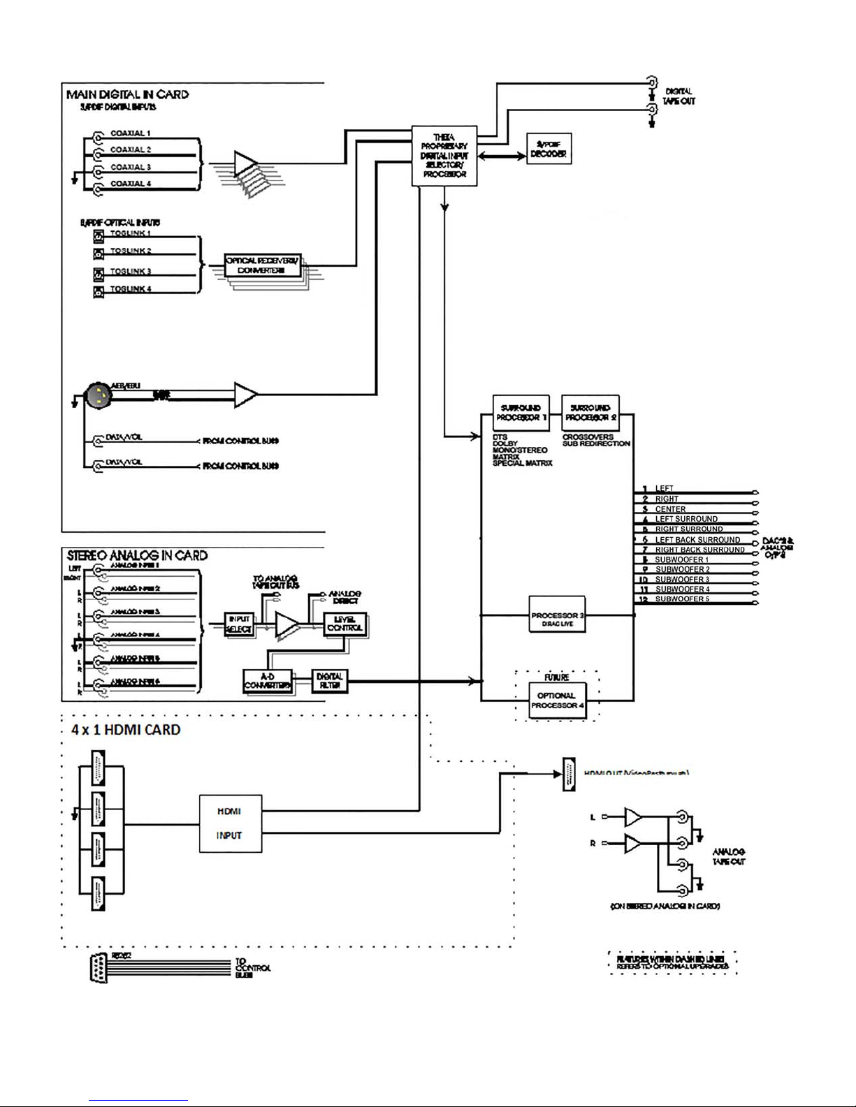
Casablanca IV Block Diagram - Input Processing Sections
Figure 1—Input processing block diagram
10
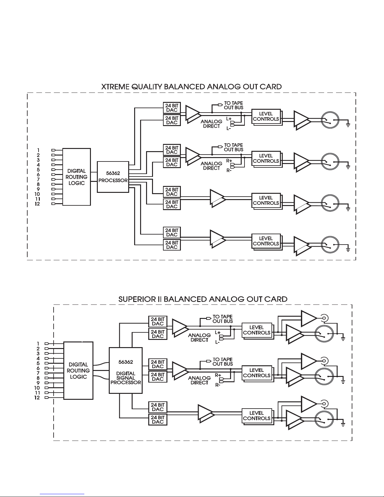
Casablanca IV Block Diagram – DAC, Analog and Digital Out Sections – Con’t
PREMIUM BALANCED OUT CARD
Figure 2 - Block Diagram of Premium DAC board
SUPERIOR II BALANCED/UNBALANCED OUTPUT CARD
Figure 3 - Block Diagram of Superior II DAC board
11
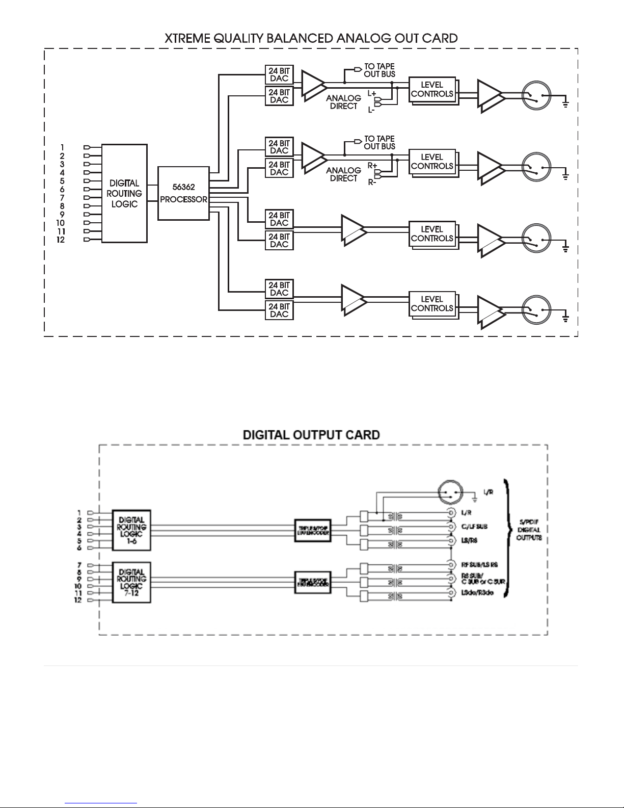
Figure 4 - Block Diagram of Xtreme D-2 4-Channel DAC board
Figure 5 - Block Diagram of Digital Output board, showing all options
Note: Digital Output Card is normally supplied with 6 XLR outputs. 6 S/PDIF outputs are
12
available by special order.
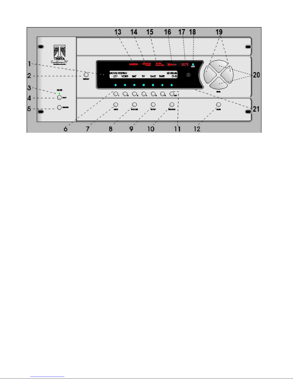
Front Panel Layout
Figure 6 - Front Panel Layout
1. 40 character by 2 row blue vacuum florescent display (VFD).
2. DISPLAY button. Temporarily overrides the VFD brightness display setting in the SETUP/INP page 1 submenu.
3. POWER LED. Lights when the Casablanca IV is in standby mode.
4. MAIN POWER button. After the rear panel MAIN POWER switch is turned on, press the front panel POWER button to exit
standby mode. The VFD will display the last selected INPUT SELECT menu. Pressing this button again will place the
Casablanca IV into standby mode and the LED above the front panel POWER button will light.
5. REMOTE POWER button. Activates/deactivates the REMOTE POWER jack on the rear panel.
6. Buttons 1 through 6. Used to select a desired input on INPUT SELECT pages, or parameter to change when in a submenu.
The LED above the button lights when the button is pressed. These buttons are referred to as the INPUT SELECT buttons.
7. MODE button. Activates the MODE select menus for the currently selected input.
8. TAPE OUT button. Used for routing audio INPUT signals to the TAPE OUT jacks.
9. SET-UP button. Used for setting speaker configurations/levels/delays, analog input levels, naming inputs, setting the display &
remote power jack time-out delays, and accessing additional surround parameters, and all other SETUP functions.
10. BALANCE button. Sets temporary speaker balance configurations and analog input levels to compensate for different program
characteristics.
11. A-D button. Sequences through input jacks mapped (assigned) to the active INPUT SELECT button.
12. MUTE button. Mutes/unmutes all audio outputs with the exception of the TAPE OUT jacks.
13. HDMI indicator. Lights when the unit is turned on. It is one indicator that the unit accepts HDMI
14. DOLBY TRUEHD indicator. Lights when the unit is turned on. Shows that the unit processes Dolby’s lossless codec.
15. DTS-HD MASTER AUDIO indicator. Lights when the unit is turned on. Shows that the unit processes DTS lossless codec.
16. DIRAC LIVE® indicator. Illuminates when Dirac Live® digital room correction and optimization filters are in use.
17. JITTER JAIL II™ indicator. Illuminates when Jitter Jail II jitter reduction circuitry is engaged.
18. LOCK light. Lights when a valid digital signal is detected on the selected input.
19. LEVEL LEFT and RIGHT buttons. Shifts audio balance to the left and right when the BALANCE function is selected, adjusts
the master volume within submenus when the LEVEL UP/DOWN buttons are to be used for parameter value editing, used to
toggle between the 2 input select pages, shifts to the next character when editing names.
20. LEVEL UP and DOWN buttons. Increases/decreases master volume. Also used to increment/decrement values in most edit
modes, and shifts FRONT/REAR audio balance in BALANCE submenu.
21. 1 through 6 LED indicators. Light when buttons 1 through 6 are selected.
13
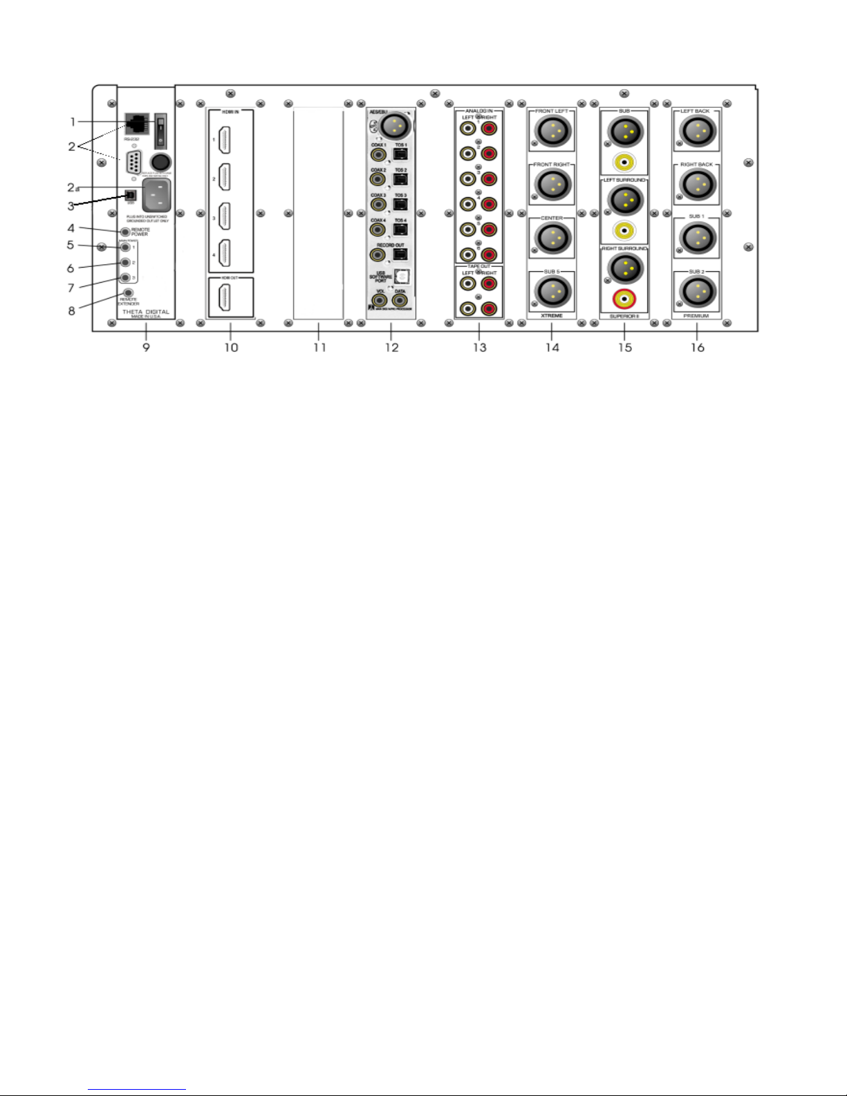
Rear Panel Layout
1. Main Power Switch. Master power switch. Disconnects AC to all circuits. It is recommended that this be left ON
at all times during regular use, except when cables are connected/disconnected or when the unit will not be used
for an extended period of time.
2. RS232 DB9, and RJ45 connectors. The DB9 is the preferred connector for external RS-232 control.
2a. AC Power Connector: 3 wire, IEC 320 connector with an EMI filter.
3. USB Connector: Preferred connector for firmware updates.
4. Remote Power jack. Activated/deactivated when associated front panel or remote button is pressed/pressed
again.
5. Main Power 1 jack. Activated/deactivated when front panel POWER button is pressed/pressed again. All Main
Power jacks can output a 12V pulse (variable duration) or continuous 12VDC.
6. Main Power 2 jack. Activated when front panel POWER button is pressed once, plus x seconds. X represents the
time value that is stored in the SET-UP/GLOBAL/REM PWR/MTIM parameter. This jack is deactivated when the
front panel POWER button is pressed again (putting the Casablanca IV in Standby mode).
7. Main Power 3 jack. Activated when front panel POWER button is pressed once, plus two times x seconds. X
represents the time value that is stored in the SET-UP/GLOBAL/REM PWR/MTIM parameter. This jack is
deactivated when the front panel POWER button is pressed again (putting the Casablanca IV in Standby mode).
8. Remote Extender jack. An externally mounted (remote) Infrared (IR) receiver plugs into this miniature stereo
phone jack. (Its signal must be demodulated). Please refer to Appendix C on page 89 for additional information.
9. Power Supply Module.
10. HDMI Input/output card. Accepts up to 4 HDMI 1.4 inputs (compatible with HDMI 1.1, 1.2, 1.3, etc.) Provides one
HDMI 1.4 output. Audio is processed within the Casablanca IV. Video is passed through untouched.
11. Reserved for future use.
12. Digital Input card. This card provides one AES/EBU (balanced XLR) input, 4 each coaxial digital and Toslink
inputs, one each coaxial and TosLink outputs, one USB (Dirac/Software) connection There are two Volume Data
Out ports.
13. Analog Input card. Six stereo RCA inputs are provided for line level analog output devices such as VCR, laserdisc,
CD and DAT players, phono preamplifiers, external D/A converters, tape decks, AM/FM tuners, etc. There are two
pairs of analog tape outs for recording purposes, whose source can be selected in the TAPE OUT menu.
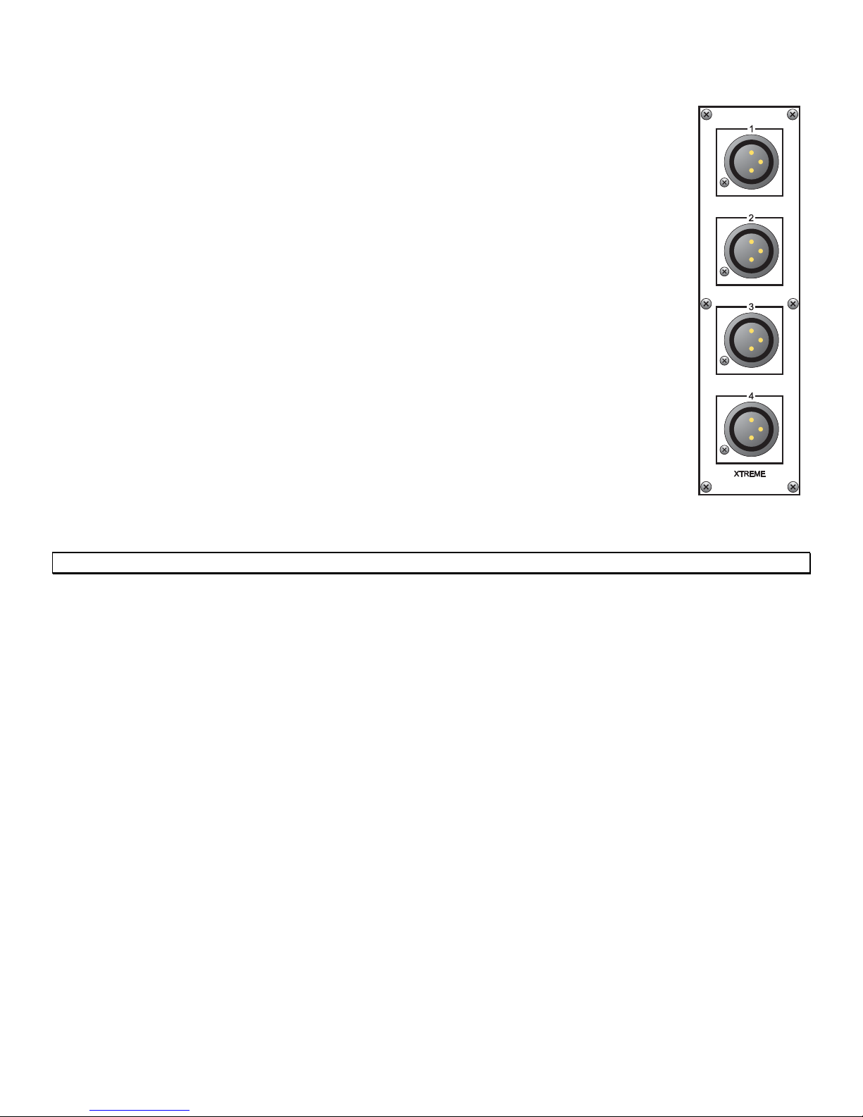
14. First Analog Output card. This slot could contain one of the following: A four-channel Xtreme D-2 quality DAC
(pictured), a four-channel Premium quality DAC card, or a 3-channel Superior II quality DAC card. The 3-channel
Superior II balanced cards also has single-ended outputs. The Xtreme D-2 card and the Premium card do not have
single-ended outputs. The channel sets that can be routed to a Superior II, Premium or Xtreme D-2 card (in any
DAC slot) are listed on pages 16 and 17 respectively, as well as in the specifications section of this manual.
15. Second Analog Output card. This slot could contain one of the following options: A four-channel Xtreme D-2
14
Figure 7 - Rear Panel Layout

quality DAC, a four-channel Premium quality DAC card, or a 3-channel Superior II quality DAC card (pictured). If
only two 3-channel balanced analog output cards are installed, this slot would typically contain outputs for sub, left
surround and right surround channels.
16. Third Analog Output card. This slot could contain one of the following options: A four-channel Xtreme D-2 quality
DAC, a four-channel Premium quality DAC card (pictured), or a 3-channel Superior II quality DAC card.
* * *
A Digital Output card can be installed in any available output slot. This card has 12 digital output channels.
15

Figure 8 - All Superior II D/A Card Options
16
Each Premium and Xtreme D-2 DAC card can have one of the following speaker sets (channels) assigned to them,
regardless of which DAC slot it (they) are installed to:
Front Left, Right, Center,or Sub 5
Front Left, Right, Surround Left, Right
Sub 1, Sub 2, Sub 3, Sub 4
Surround Left, Right, Sub 3, Sub 4
Front Left, Right, Sub 1, Sub 2
Surround Back Left, Right, Sub 1, Sub 2
Surround Back Left, Right, Sub 2, Sub 3
Center, Sub 1, Sub 2, Sub 3
Center, Sub 1, Surround Back Left, Right
Front Left, Right, Surround Back Left, Right
Surround Back Left, Right, Surround Left, Right
Front Left, Right, Center, Sub 1
Sub 1, Sub 2, Sub 3,or Sub 5
Surround Back Left, Right, Sub 5, Sub 1
Surround Back Left, Right, or Sub 5, Sub 2
Center, or Sub 5, Surround Back Left, Right
Center, or Sub 5, Surround Left, Right
Sub 2, Sub 3, Sub 4, or Sub 5
Front Left, Right, Center, Sub 2
Front Left, Right, Center, Sub 3
Front Left, Right, Center, Sub 4
Sub 2, Sub 3, Surround Left, Right
Sub 2, or Sub 5, Surround Left, Right
Center, Surround Back Left, Right, Sub 2
Center, Surround Left, Right, Sub 2
Figure 9 - Xtreme DAC
Note: In figure 9, each output is shown with a number 1-4. Channel labels are available to better identify each output.
17
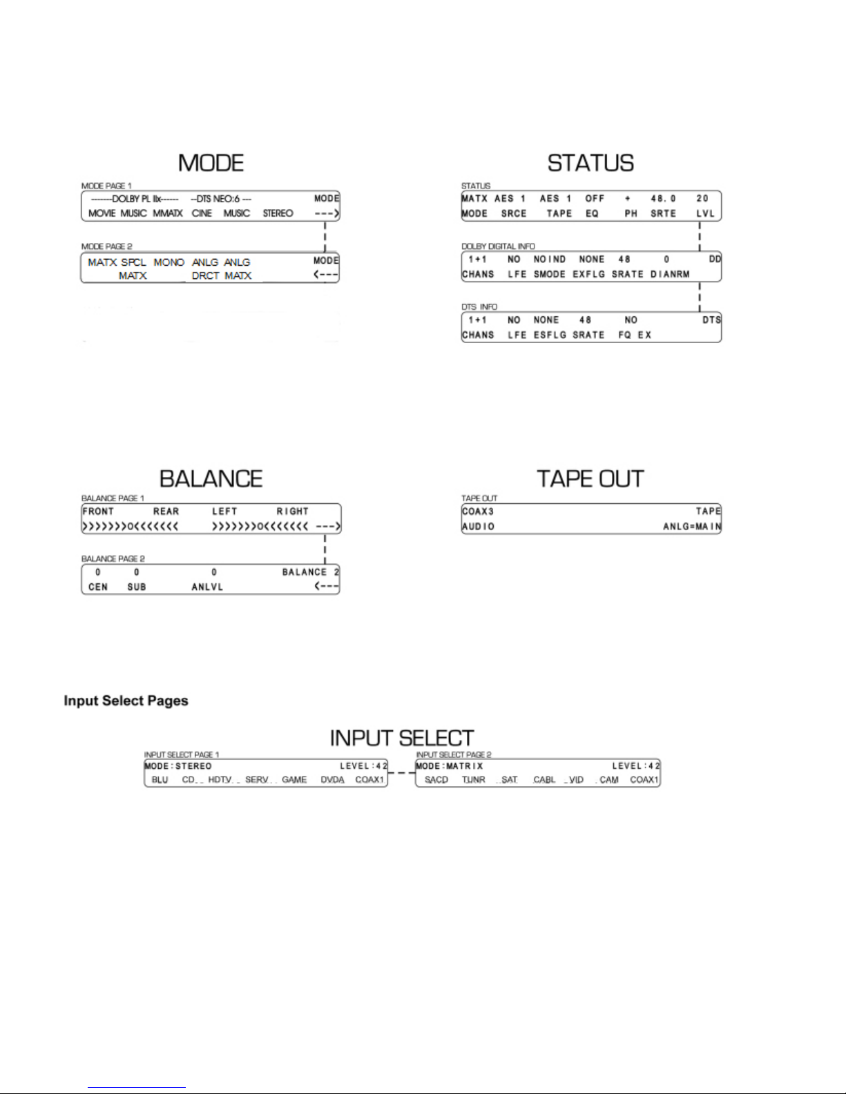
Menu Maps
Function Menus and Pages
Figure 10-Mode, Status, Tape Out Menus and Input Select Pages
18
19

Introduction to the User interface
The menu system within the Casablanca IV consists of 1 to 3 layers, with the exception of the SET-UP menu.
Some menus have multiple pages, which can be accessed by pressing the A/D button, with the exception of the
INPUT SELECT menu, which uses the LEFT/RIGHT buttons and the MATX MODE that uses the LEVEL
UP/DOWN buttons. . When a menu has additional pages associated with it, a right or left arrow will be displayed
in the bottom right corner of the VFD. Please refer to figures 18 and 19 for an overall view of all menus, submenus
and menu pages.
The SETUP menu contains a number of submenus, organized by setup function. All configuration parameters
which can be stored for each INPUT SELECT button (by input). They are accessed in one of the 3 SETUP/INPUT
submenus. Setup parameters that are not stored individually for each INPUT SELECT button are accessed in
the two SETUP/GLOBAL submenus. All macros can be executed via the SETUP/MACROS submenu.
Once a parameter is selected for editing, pressing the LEVEL UP/DOWN buttons edits the parameter value,
storing it at the same time. On any page, if the LEVEL UP/DOWN buttons are not used for editing a parameter
value, they will adjust the master volume. Where the LEVEL UP/DOWN buttons are used for editing a parameter
value, the LEVEL LEFT/RIGHT buttons will adjust the master volume. An exception to this is the first BALANCE
page and the pages where input select buttons and input jacks are named. In a few cases simply pressing the 1-
6 buttons makes a selection.
The function buttons are defined as the MODE, TAPE OUT, SET-UP, and BALANCE buttons. To exit a function
the same function button can be pressed multiple times to exit, or another function button can be pressed at any
time.
Before you begin
With all input options installed in a Casablanca IV, there are up to 19 input jacks: 6 pairs of stereo analog audio,
9 digital audio and 4 HDMI. Each jack can be named for the piece of equipment plugged into it. It is
recommended that this step be done first. (SETUP/GLOBAL/JACK NAMES).
Each INPUT SELECT button can have up to 3 audio jacks mapped, or assigned. The INPUT SELECT button
should be named for the function it will serve. There are a total of 12 INPUT SELECTs on two pages. Pressing
the LEVEL LEFT/RIGHT buttons will toggle between these two pages of 6 inputs each.
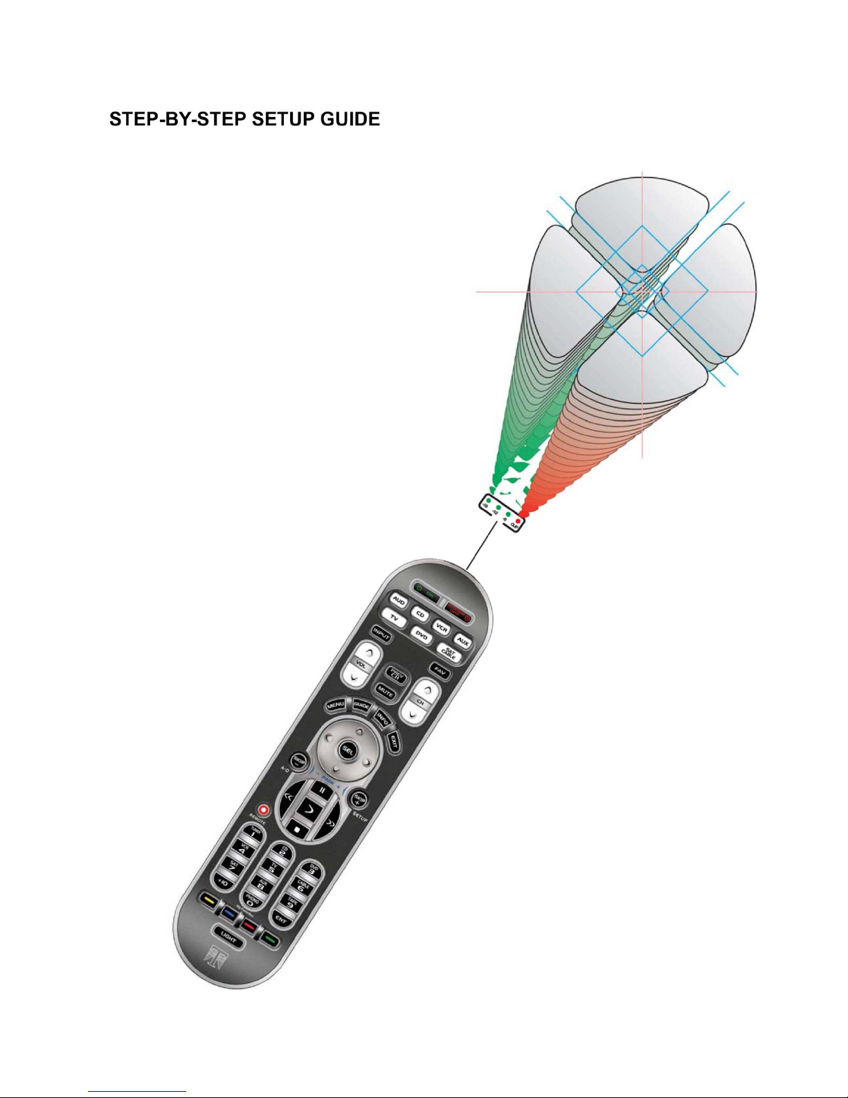
The procedure for setting up each INPUT SELECT is outlined in the Step-By-Step Setup section.
Note: The order in which input jacks are assigned to an INPUT SELECT button determines the search order.
Please refer to page 44 for additional information on source assignment (search order). When more than one
input jack is assigned to a single INPUT SELECT button, toggling the A-D button [when the INPUT SELECT page
is active in the front panel display] will select the next assigned input jack – both audio and video.
20
21

Casablanca IV Default Settings
These are the default settings as the unit is received from the factory. Also, should it be necessary to re-set the unit,
these values will be restored. Of course, all inputs can be renamed and the assigned sources can be changed.
Inputs
Source Name Source
#1 BLU HDMI1
#2 CD AES1
#3 HDTV HDMI2
#4 SERV COAX1
#5 GAME HDMI3
#6 DVDA HDMI4
#7 SACD TOS2
#8 TUNR COAX2
#9 SAT COAX3
#10 CABL TOS1
#11 VID ANALOG1
#12 CAM ANALOG2
Available Channel Outputs
As ordered. The typical configuration is 7.1 analog output. 5.1 through 7.5 analog and 12-channel digital outputs are
available.
Speaker Configurations
All speakers crossed over at 80 Hz; 24 dB per octave low-pass filter; 12 dB per octave high-pass filters
Speaker Levels and Delays
Both set to zero (0)
Master (Lip-Synch) Delay
Set to 0
Dolby and DTS
Setup for 7-channel audio.
Dirac Live® 96 kHz
Off
Jitter Jail™ II
Off
Mode
Matrix
22
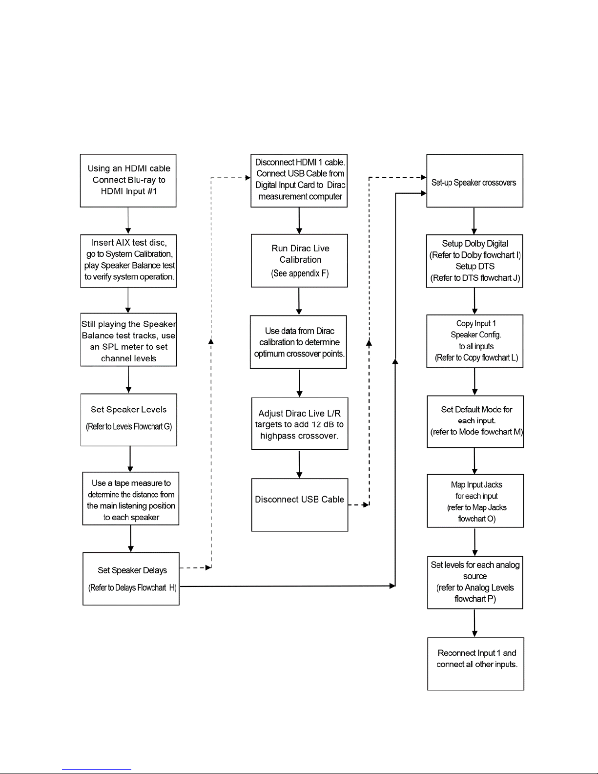
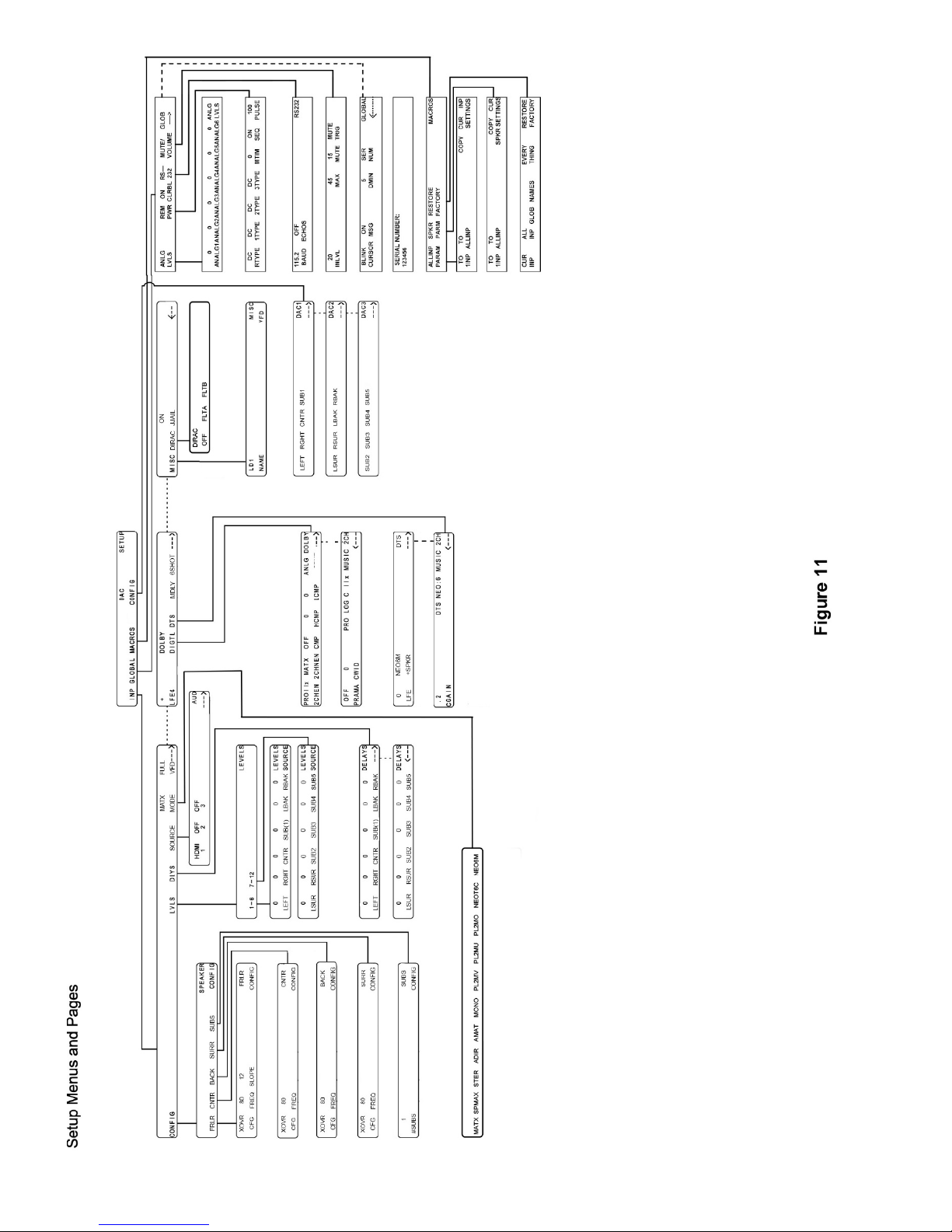
Overall Setup Procedure Flowchart
This flowchart shows all steps required to set up the Casablanca IV in order to achieve the best possible sonic
performance and to provide the simplest operation for all users. Follow solid and dotted lines to include Dirac Live® 96
kHz Room Correction and Optimization. Follow solid lines, only, to set-up without including Dirac Live® 96 kHz.
Instructions and detailed flowcharts for each step are contained on the following pages.
Figure 12: Casablanca IV Basic Set-up Flow Chart
23
Casablanca IV provides a comprehensive set of speaker configuration settings. With the inclusion of Dirac Live® 96
kHz, these settings should allow any speaker to perform optimally regardless of speaker type. The following procedure
is merely a guideline: room acoustics, speaker design/quality, music/film type, and personal preferences all have a part
Step by Step Speaker Configuration
in these settings.
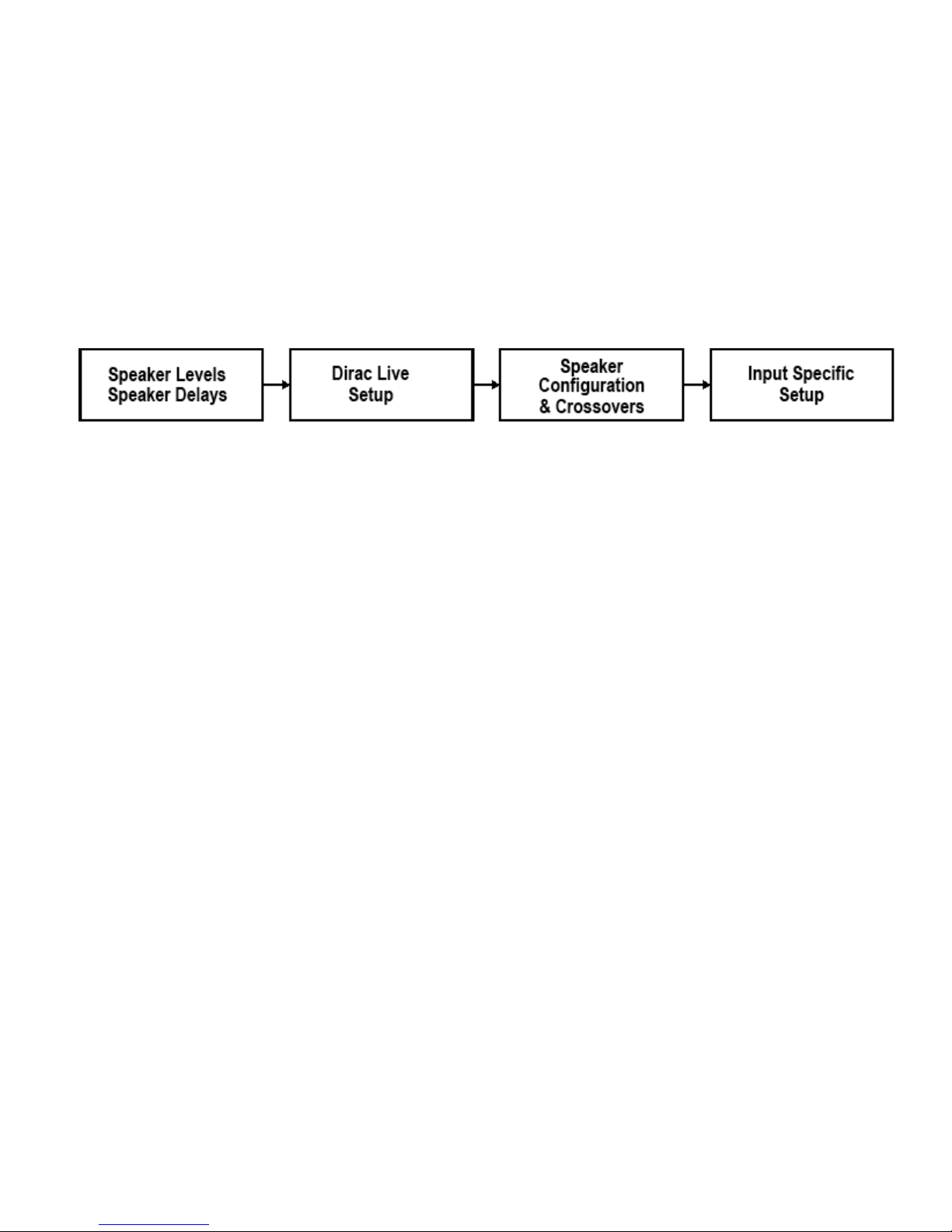
Using the Setup menu map diagram [Figure 11] on page 18 in this manual is recommended.
There are four major steps to setting up your Casablanca IV. In recommended sequence, they are:
Individual speaker levels: compensates for different speaker and amplifier efficiencies.
Delays: compensates for different speaker distances from the listening position.
Dirac Live®: Measures the exact performance of each loudspeaker in the system and applies mixed phase IIR and FIR
filters to correct for non-optimum frequency and phase response and provides a guide for selecting crossover points.
Speaker Configuration & Crossovers: permits proper signal routing in the Casablanca IV and proper blending of main
and subwoofer signals. Enables all speakers present in the system.
Input Specific Setup: All parameters that are specific to an individual input select button.
Each step plays a pivotal role in the overall sonic performance and should receive equal attention and care in
adjustment.
Speaker Levels
Setting up the speaker levels is best accomplished by playing the supplied AIX test disc and an SPL meter. If the meter
has ‘weighting’ options, “C” is preferable.
10) With Input # 1 selected and your Blu ray player connected via HDMI, begin playing the Speaker Balance test tracks.
Go to the speaker levels submenu.
a) With the SPL meter placed in the main seating position pointing at the ceiling, play the track for the front left
speaker and bring up the master volume (using the LEVEL LEFT button) until the SPL meter reads 70 dB.
b) Repeat this procedure for the center speaker using the CNTR level control.
c) Play the track for the front right speaker and, with the SPL meter in the same position, adjust the RGHT
speaker level up/down until the SPL meter reads 70 dB.
d) Play the track for the left surround speaker and adjust the level until the SPL meter reads 70 dB.
e) Play the track for the right surround speaker and adjust the level until the SPL meter reads 70 dB.
f) Play the track for the left back speaker and adjust the level until the SPL meter reads 70 dB.
g) Play the track for the right back speaker and adjust the level until the SPL meter reads 70 dB.
h) Play the track for subwoofer adjustment. With the subwoofer level trim on the Casablanca IV set to “0”, use
the volume control on the powered subwoofer to adjust the SUBWOFFER output until the SPL meter reads
76 dB.
i) If the system has more than a single subwoofer, using each subwoofer individually, repeat step “h” above
to set the level for each subwoofer in the system to an indicated 76 dB on the SPL meter.
j) If the system has more than a single subwoofer, you must adjust the SUBWOOFER output level on the
Casablanca IV to compensate for the additional subwoofer output. If you are using Dirac Live®, make these
level adjustments after Dirac Live® calibration.
k) With two subs set the SUBWOOFER output level for each subwoofer to -3 dB
l) With 3 subwoofers, set the SUBWOOFER output level for each subwoofer to -4 dB
k) With 4 subwoofers, set the SUBWOOFER output level for each subwoofer to -5 dB.
l) With 5 subwoofers, set the SUBWOOFER output level for each subwoofer to -6 dB.
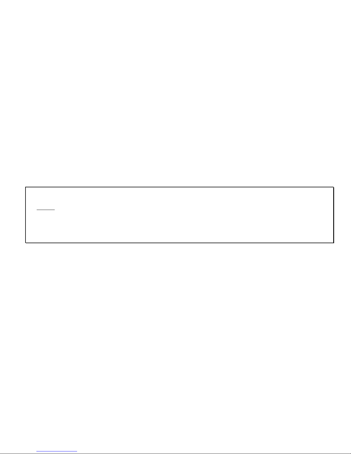
Speaker Delays
11) With Input # 1 selected, go to the DELAYS submenu.
a) Using a tape measure, measure the distance between the principal listening position and the center of each
speaker. Write down the distances.
b) Enter the measured distances to the nearest foot from the primary listening position to each speaker. Your
Casablanca IV will automatically adjust the delays to assure simultaneous arrival of sound from each channel
at the primary listening position.
24
Dirac Live® 96 kHz Setup
In a 2002 article in The Audio Critic, Dr. Floyd Toole, then Vice President, Engineering for Harman Industries
wrote: “The room is the final audio component. Rooms audibly modify many aspects of sound quality. All rooms
are different.” Dr. Toole went on to say, “Accurate high-resolution in-room measurements along with acoustical
corrections and equalization are necessary to deliver truly good sound to listener’s ears in homes and in studios.”
Dirac Live® is a state-of-the-art measurement and room optimization suite that finally allows users to follow Dr. Toole’s
admonition. We recommend that initial setup of your Casablanca IV be done without using Dirac Live®. After proper
operation of your basic system has been verified, please see Appendix F for details on Dirac Live® set-up.
Once Dirac Live® data acquisition is complete, please use the actual in-room performance data and revise crossover
points and slopes where necessary.
Dirac Live® set-up is covered in Appendix F
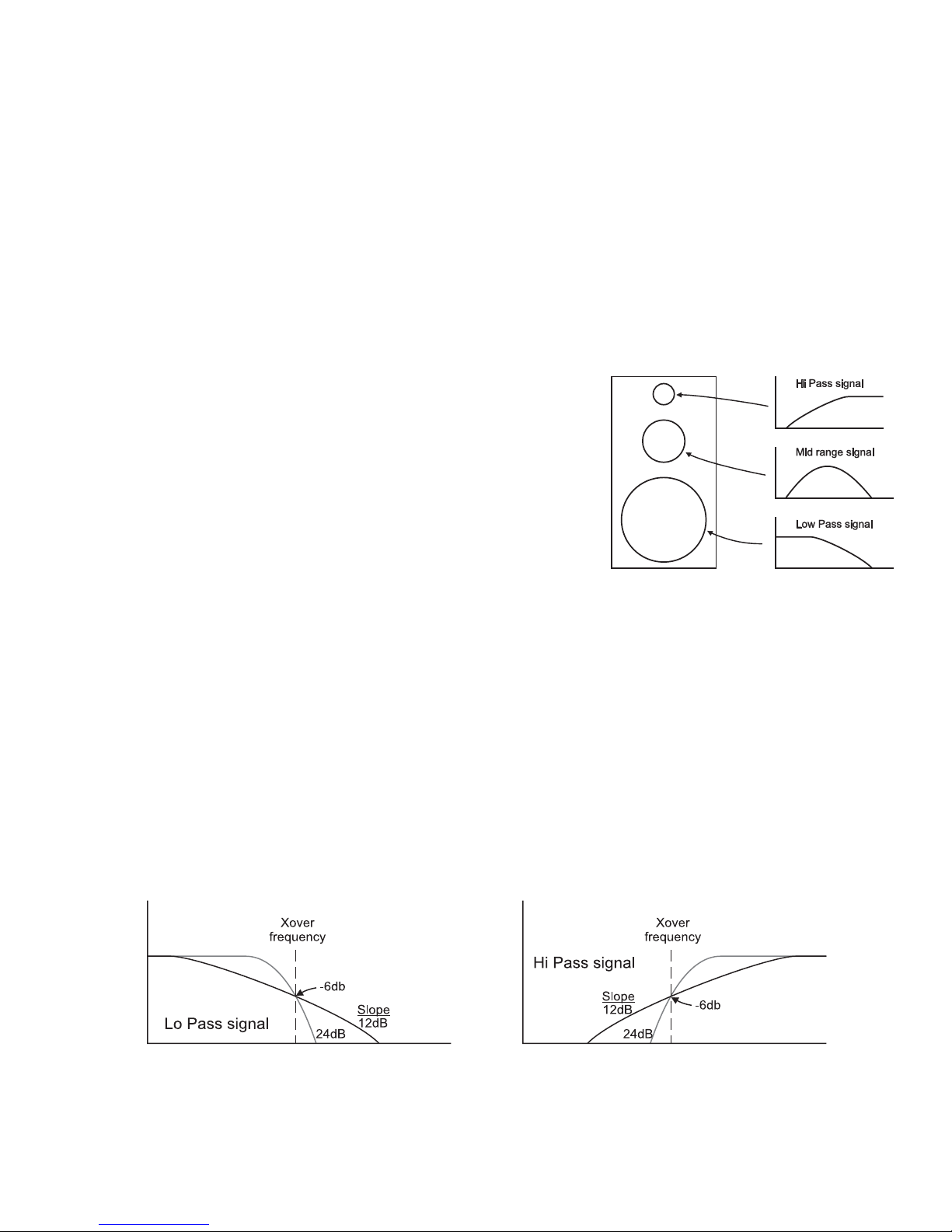
Speaker Configuration & Crossovers
Crossovers are most commonly located in a speaker cabinet. Their purpose
is to keep energy at certain frequencies from reaching specific speaker
elements (drivers), [e.g. keeping unwanted bass energy from the tweeters
(see diagram at right).] Home theater applications use crossovers in the
surround processor to send low pass information to a subwoofer and limit
the low pass information sent to the main speakers. The purpose of this
section, SPEAKER CONFIGURATION, is to properly set up the Casablanca
IV’s internal crossovers for optimal sound as well as enable all speakers in
the system.
In this manual, a Speaker Set is defined as one or more speakers that are
manipulated via a common parameter. For example, the crossover
parameters for both the front left and right speakers are manipulated in the front left/right configuration submenu since
the desired effect for the left speaker is also appropriate for the right. The other speaker ‘sets’ in the Casablanca IV are
the [surround left and right], the Back [bacl surround left and right], and the [center]. The speaker sets will be delimited
by [ ].
Full speaker configurations are stored separately for each of the 12 input select buttons. This procedure will guide the
user to set all configuration parameters for input # 1, and then copy these parameters to all other input select buttons.
In the Speaker configuration submenu, buttons 1-5 will access additional menus to setup a particular speaker or set of
speakers. Button 6 will turn on the back speakers, if configured in the system
Linkwitz-Riley
While previous versions of the Casablanca allowed for several types of crossovers, with the Casablanca IV only
Linkwitz-Riley crossovers are available. The significant advantage of Linkwitz-Riley filters over all other filter types
is that Linkwitz-Riley filters exhibit zero phase difference between the high-pass and low-pass filters at all
frequencies. They always match.
A note on crossovers
Selecting crossover options can at first appear daunting. Traditionally, crossovers have been set by reading the
specification sheet for one’s loudspeakers, noting the reported cut-off frequency and using that information to choose
the crossover frequency. The Casablanca IV is rare: the inclusion of Dirac Live® 96 kHz gives the calibrator the exact
in-room response of every speaker in the system and allows improved selection of crossover frequencies.
Linkwitz-Riley Crossover Diagram
25
A note on home theater
There are a few common misconceptions about home theater and bass reproduction. Chief among them is that the ".1"
or "LFE" channel contains most or all of the bass information. This is unequivocally false. The LFE channel contains
sound effects such as explosions, rumbling and the like. All other channels (left, center, right, left surround, right
surround) often contain an equal amount of bass. Their bass, however, tends to be more related to the soundtrack,
vocal material or localized sources such as a drum beating behind the listener. This is important to understand when
setting up crossovers in the coming section.
Another misconception is that the center channel is "fill" and is of minor importance. Again, this is false. The center
channel contains the lion's share of important information (particularly dialog) in the cinematic experience. It is critical
that the center speaker be of the highest quality possible and special attention be given to its mounting and positioning.
Speaker Configuration & Crossovers – Con’t.
Speaker configuration will have been set to the owner’s specifications at the factory when the Casablanca IV was built
or upgraded. If the as-received configuration is wrong or has changed, please follow the steps below. Otherwise, go to
1) Select Input # 1.
Connect a digital source to HDMI Input 1 jack. If no sound is heard, press the A-D button until HDMI 1 appears in the
VFD above the A-D button.
2) With Input button # 1 selected:
a) Go to the SUB CONFIG submenu.
b) Set #SUBS to the number of subwoofers that are to be configured into the system.
c) If no subwoofer is present, set #SUBS to 0. The subwoofer Full Range/Crossover setting has no effect in
this case.
Note: You will now be directed to set up crossovers as if a sub were present. There are some general rules that the
Casablanca IV follows in the special case of no subwoofers:
Case 1 - The front left/right speaker configuration is set to FULL:
If the center speaker is set to "crossover", its low pass signal will be sent to the left/right channels.
If the surround left/right and/or the back surround speaker configuration is set to “crossover” its low pass signal will
be sent to the front left/right speakers.
3) Determine which speaker sets ([Front left/right], [Center], [left/right Surrounds], [back Surrounds]) need crossovers.
a) If no speaker set is present, the CFG setting should be OFF. If there are no surround speakers, the surrounds
should be set to OFF.
b) When a speaker set is set to OFF, its signal is not lost. If the Center speaker is set to OFF, the center channel
signal will be routed equally to the front left/right speakers; if the back surround speakers are set to OFF and
the program material contains back surround material, back surround channel signals will be rerouted to the
surround left/right speakers
It is preferable that none of the speakers need a crossover, but is rarely practical. Keep in mind that with a 5.1 signal
(Dolby Digital or DTS), any speaker can be confronted with a full amplitude signal at any frequency. Generally
speaking, the smaller the speaker, the more limited its bass capabilities. If a speaker set doesn't need to be crossed
over, that speaker sets’ configuration (CFG) setting should be FULL. If all speaker sets are set to "FULL RANGE",
the following section (Steps 5-9) on setting crossovers may be skipped.
5) Do the following for each of the four speaker sets (LT/RT, CEN, SURRND, BK SRND):
a) Go to that speaker sets’ configuration menu.
b) Review the frequency response as measured using Dirac Live® 96 kHz.
c) Using the Dirac Live® data, determine the low frequency capability of each speaker
d) If the speaker’s measured response does not extend below 30 Hz, set the CFG to XOVER.
e) If the speaker’s measured response extends below 30 Hz, set the CFG setting to FULL.
26
Speakers in a typical 5.1 system
Figure 13: 5.1 System Speaker Layout
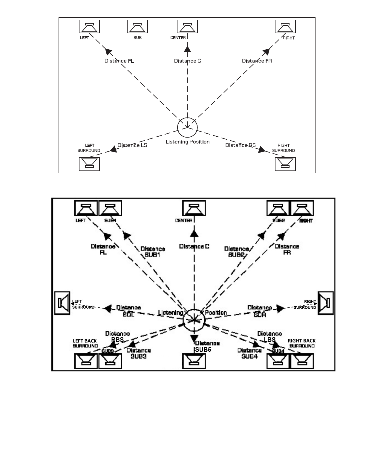
Figure 14: 12 Channel System Speaker Layout
Speakers in a typical 12-channel system
27

Dolby Digital, DTS Setup
The center and left/right surround speaker levels and delays can be different for Dolby Digital and DTS sources. There
are separate SETUP submenus designed just for these modes. When the mode is Dolby Digital or DTS, the center and
surround delays will work together with changes made in the above DLYS submenu. The values of the levels set in the
Dolby Digital and DTS Setup submenus will be added to (or subtracted from) the level values in the SETUP/INP/LVLS
submenu.
12) a) Play a Dolby Digital 5.1 movie.
b) Go to the Dolby Digital setup submenu – page 2.
c) If desired, set the center speaker delay.
d) If desired, set the surround delay.
e) Set the center speaker level and the surround speaker level to 0. Please refer to the SETUP/Dolby Digital
section in this manual for additional information regarding setting the Dolby Digital center and surround levels.
f) If the incoming signal is 5.1 and the Surround Back channels are being used, set the +SPKR value to the
process which will be used to create the additional channels. This decision will be made solely by listening
to which sounds best to the user.
g) Go to the Dolby Digital setup submenu – page 3.
h) If the incoming signal is EX flagged and the Surround Back channels are being used, set the +SPKR value
to the process which will be used to create the additional channels. This decision will be made solely by
listening to which sounds best to the user.
Remember that these values will be in effect only when the MODE is Dolby Digital and specific flags are present.
13) a) Play a DTS encoded CD or movie.
b) Go to the DTS page 1 Setup submenu.
c) If desired, set the center speaker delay.
d) If desired, set the surround delays.
e) Set the center speaker level.
f) Set each surround speaker.
g) Set the LFE level at 0 for DTS movies, or -10 for DTS music. (The user can choose to use two separate
input select buttons, one for DTS movies and one for DTS music, all parameter values being the same except
for the LFE setting).
h) If the incoming signal is 5.1 and the Surround Back channels are being used, set the +SPKR value to the
process which will be used to create the additional channels. This decision will be made solely by listening
to which sounds best to the user.
These parameter values apply only when the MODE is DTS.
Remaining Setup
14) Now that the speaker configuration, crossovers, levels and delays have been set up for input select button #1, they
should be copied to all input select buttons as a good starting point. Do this in the MACROS submenu when input
select # 1 is the current input.
15) Each input select button has a default mode assigned to it. (To see the Default Modes, please see page 22.) The
default mode for a given input select button is set and stored in the first SETUP/INPUT page. As the user scrolls
through the list of modes, there are 2 positions in this list that are not currently used. In these positions, the word
SKIP will be displayed.
a) Press input select button #1.
b) Go to the SETUP/INP – page 1 submenu.
c) Set the applicable default MODE.
d) Repeat steps b and c for each input select button.
16) An input signal is “processed” a certain way depending on which MODE is currently selected
17) The audio SOURCE pages allow the user to map up to three audio sources to the currently selected input. It is
recommended that all other displayed jacks in this submenu be cleared if they are not to be used. Please refer the
Mapping Jacks and Search Order sections of this manual for additional details about mapping input jacks to a given
Input Select button.
Verify that the desired rear panel audio input jacks are properly mapped to each Input Select button that is to be
used.
a) Select input # 1.
b) Go to the AUDIO SOURCE submenu.
28

c) Map all appropriate rear panel audio input jacks.
d Select input # 2.
e) Repeat steps a through e for all used input select buttons.
18) All analog sources must have their input levels set in order to obtain the best signal to noise ratio as well as to ensure
that no clipping occurs.
a) Go to the ANALOG LEVELS submenu.
b) Select the first set of jacks with an analog input jack assigned to it.
c) Adjust the analog input level.
d) Repeat steps b and c for each analog source.
Make adjustments so that during the most aggressive passages, the red clip light never comes on, but the –6 or –
12 lights are on.
29
 Loading...