

Theta Digital Casablanca II Owner's Manual
THETA DIGITAL
CORPORATION
Casablanca II
Owner’s Manual
V 2.01
Digital Done Right
™

PREFACE
You have just acquired the most advanced c omponent f or the control and processing of audio and video ever to
have been developed.
IMPORTANT
CONGRATULATIONS
Save all packaging in a dry place away from fire hazards. Your Casablanca II is a precision electronic instrument
and should be properly packaged any time shipment is m ade. In the unlikely event that you have to return your
Casablanca II to the factory for service, or if you send it to us for updating, the original packaging will best protect
the unit from shipping damage.
In order to achieve the fullest flexibility and enjoyment from your Casablanca II, we at Theta recommend that you
read this manual in full before connecting the unit to your audio/video system.
WARNING
United Stated law prohibits disposition of these com modities to Libya, Laos, North Korea, Cambodia or Cuba
unless otherwise authorized by the United States.
NOTE:
This equipment has been tes ted and found to c om ply with the limits for a Clas s B digital device, pursuant to Part
15 of the FCC rules. These lim its ar e designed to provide reasonable pr otection against harm ful interf erence in
a residential installation. This equipment generates, uses and can radiate radio f requency energy and, if not
installed and used in accordance with the instructions , m ay cause harm ful interf erence to radio comm unic ations.
However, there is no guarantee that interference will not occur in a particular installation. If this equipment does
cause harmf ul interferenc e to radio and television reception, which can be determ ined by turning the equipment
off and on, the user is encouraged to try to correct the interference by one or more of the following measures:
* Reorient or relocate the receiving antenna.
* Increase the separation between equipment and receiver.
* Connect the receiver into an outlet on a circuit different from that which the Casablanca II is connected to.
Acknowledgments
Casablanca II is manufactured under license from Dolby Laboratories. “Dolby”, “Pro Logic”, “AC-3”, and the
double-D symbol are tradem ar ks of Dolby Laboratories. Conf idential Unpublished Work s. Copyright 1992-1997
Dolby Laboratories, Inc. All rights reserved.
Casablanca II is manufac tured under lic ense fr om Digital T heater Systems. Inc. US Pat. No 5,451,942 and other
worldwide patents issues pending. “DTS” and “DTS Digital Surround” are trademarks of Digital Theater
Systems, Inc. 1996 Digital Theater Systems, Inc. All rights reserved.
Casablanca II is manufactured under license from SRS Labs, Inc. US Pat No 5,319,713, 5,333,201 and
7,771,295. “Circle Surround
2000-01 Theta Digital Corporation. All rights reserved.
Written and illustrated by Glenn Buckley.
This manual is also available for download as a PDF file at Theta Digital’s website. http://www.thetadigital.com
No part of this publication may be reproduced or transmitted in any form or by any means, electronic or
mechanical, for any purpose, without the express written permission of Theta Digital Corporation.
TM
” and the Circle Surround Logo are trademarks of SRS Labs, Inc. 1994-1998.
ii
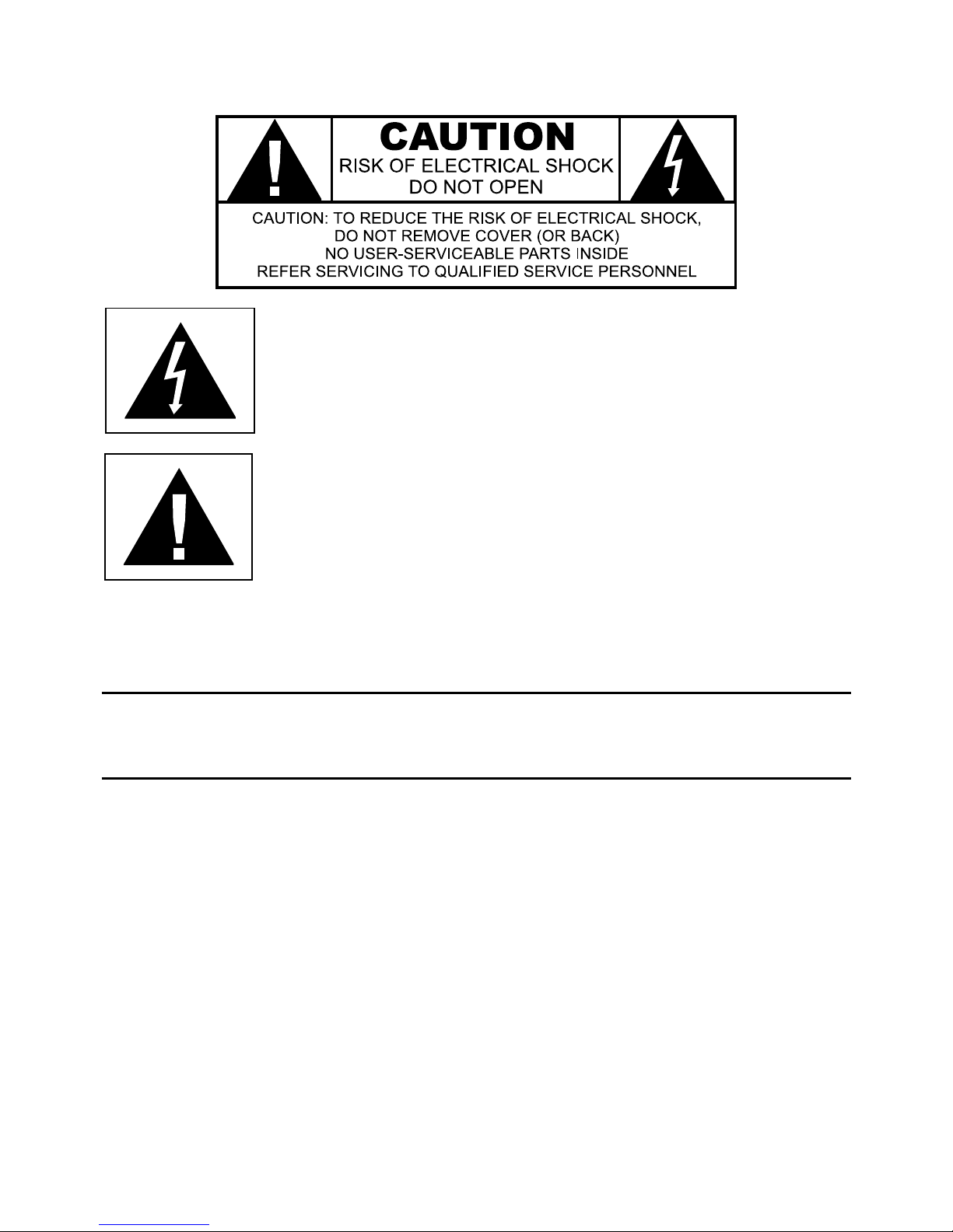
The lightning flash with arrowhead symbol, within an equilateral
triangle, is intended to alert the user to the presence of uninsulated
“dangerous voltage” within the product’s enclosure that may be of
significant magnitude to constitute a risk of electric shock to persons.
The exclamation point within an equilateral triangle is intended to alert
the user to the presence of important operating and maintenance
(servicing) instructions in the literature accompanying the product.
WARNING
TO REDUCE THE RISK OF FIRE OR ELECTRIC SHOCK,
DO NOT EXPOSE THIS PRODUCT TO RAIN OR MOISTURE
CAUTION: TO PREVENT ELECTRIC SHOCK, DO NOT USE THE (POLARIZED) PLUG WITH AN
EXTENSION CORD, RECEPTACLE OR OTHER OUTLET UNLESS THE BLADES CAN BE FULLY
INSERTED TO PREVENT BLADE EXPOSURE.
iii

Casablanca II Identification Record
This inform ation is for your recor ds and f or future identif ication of the Casablanca II. Pleas e take a m oment
to fill out all pertinent data now, and as upgrades and/or options are installed.
inquiries and/or changes are requested, the serial number will be required.
SERIAL NUMBER
DATE PURCHASED
DEALER’S NAME
DEALER’S ADDRESS/PHONE
INSTALLED CARDS/OPTIONS
(Date of installation)
(Date of installation)
(Date of installation)
(Date of installation)
(Date of installation)
(Date of installation)
(Date of installation)
(Date of installation)
(Date of installation)
(Date of installation)
(Date of installation)
Whenever upgrades,
iv

SAFETY PRECAUTIONS
Please carefully read each item of the oper ating inst ruc tions and safety precautions before using this product.
Use extra care to f ollow the warnings written on the product itself and/or in the operating inst ructions. Keep
the operating instructions and safety precautions for future reference.
CAUTION: TO REDUCE THE RISK OF ELECTRICAL SHOCK, DO NOT REMOVE ANY OF THE COVER
PANELS.
NO USER-SERVICEABLE PARTS INSIDE. REFER ALL SERVICING TO QUALIFIED SERVICE
PERSONNEL ONLY.
TO PREVENT FIRE OR SHOCK HAZARD, DO NOT ALLOW LIQUIDS TO SPILL OR OBJECT S TO FALL
INTO ANY OPENINGS OF THE PRODUCT.
THIS UNIT IS SUPPLIED WITH A 3 PIN GROUNDED AC PLUG. ALWAYS INSERT THE AC PLUG INTO A
GROUNDED OUTLET. DO NOT REMOVE THE GROUND PIN OR DISABLE THE GROUND FOR ANY
PURPOSE.
BEFORE MAKING ANY CONNECTIONS TO THE CASABLANCA II, FIRST TURN OFF THE POWER AND
THEN DISCONNECT THE AC POWER CORD.
WHEN INSTALLING THE CASABLANCA II IN YOUR SYSTEM, MAKE CERTAIN TO ALLOW A MINIMUM
OF 3 INCHS OF VENTILATION ON EACH SIDE OF THE UNIT. ALSO ALLOW AT LEAST 3½ INCHS OF
VENTILATION SPACE ABOVE THE UNIT. IMPROPER VENTILATION OF THE UNIT MAY CAUSE
OVERHEATING, WHICH MAY DAMAGE THE UNIT AND CAUSE A FIRE. PLACE THE UNIT ON A SOLID
SURFACE ONLY. I.E. NOT ON CARPET, ETC.
DO NOT PLACE THE CASABLANCA II NEAR HEAT SOURCES SUCH AS DIRECT SUNLIGHT, STOVES,
HEAT REGISTERS, RADIATORS OR OTHER HEAT PRODUCING EQUIPMENT.
TO PREVENT DAMAGE TO THE ANALOG OUTPUT CIRCUITRY, BE CERTAIN NOT TO SHORT THE
OUTPUT SIGNAL PIN(S) TO GROUND. ENSURE THAT YOUR AUDIO OUTPUT CABLES DO NOT HAVE
ANY INTERNAL SHORTS BEFORE CONNECTING THEM TO THE CASABLANCA II.
IF REPLACEMENT OF THE AC LINE FUSE BECOMES NECESSARY, REPLACE ONLY WITH SAME
VALUE AND TYPE OF FUSE. NEVER BYPASS THE FUSE.
IF THE AC CORD BECOMES DAMAGED, DO NOT USE IT. IMMEDIATELY REPLACE IT WITH A NEW
ONE OF THE SAME OR BETTER RATING.
AFTER MARKET and THIRD PARTY MODIFICATIONS
Please note that any after market and/or third party modifications will void the warranty. In the case of
changing the feet on a unit, in order to prevent any damage (which will also not be covered under warr anty),
please verify that the screws being used to secure non Casablanca II f eet do not screw any deeper into the
chassis than the original ones. The original screw is 10-32 by 3/8 and goes into the chassis 1/5 inch.
v

Table of Contents
PREFACE ............................................................................................................................................................................ii
WARNING...................................................................................................................................................................... iii
Casablanca II Identification Record ................................................................................................................................iv
SAFETY PRECAUTIONS............................................................................................................................................... v
List of Figures..................................................................................................................................................................ix
List of Tables....................................................................................................................................................................x
INTRODUCTION.................................................................................................................................................................1
Getting to know your Casablanca II................................................................................................................................1
IMPORTANT NOTICE.....................................................................................................................................................2
Reference Manual Conventions......................................................................................................................................2
Glossary of Terms and Abbreviations.............................................................................................................................3
Casablanca II Block Diagram - Input Processing Sections............................................................................................. 4
Casablanca II Block Diagram - DAC and Analog Out Sections ......................................................................................6
Front Panel Layout.......................................................................................................................................................... 8
Rear Panel Layout...........................................................................................................................................................9
Menu Maps....................................................................................................................................................................12
Function Menus and Pages.......................................................................................................................................12
Input Select Pages.................................................................................................................................................... 12
Setup Menus and Pages........................................................................................................................................... 13
Introduction to the User interface.................................................................................................................................. 14
WARNING !! : PLEASE READ FIRST!.................................................................................................................... 14
Before you begin.......................................................................................................................................................14
STEP-BY-STEP SETUP GUIDE....................................................................................................................................... 15
Casablanca II Overall Setup Procedure Flowchart .......................................................................................................16
Step by Step Speaker Configuration......................................................................................................................... 17
Speaker Configuration & Crossovers.................................................................................................................... 17
Phase Perfect.................................................................................................................................................... 17
Butterworth........................................................................................................................................................ 18
Linkwitz-Riley ....................................................................................................................................................18
A note on crossovers.....................................................................................................................................18
A note on home theater................................................................................................................................. 18
Speaker Configuration & Crossovers – Con’t........................................................................................................ 19
Speaker Levels ......................................................................................................................................................... 20
Speaker Delays.........................................................................................................................................................21
Dolby Digital, DTS and Circle Surround Setup..........................................................................................................22
Remaining Setup....................................................................................................................................................... 22
Setup Flowcharts A-P................................................................................................................................................24
FRONT PANEL OPERATIONS........................................................................................................................................40
Input Select Menus........................................................................................................................................................40
Changing Inputs and Input Select Pages..................................................................................................................40
Auto-Search ..............................................................................................................................................................40
Selecting Mapped Input Jacks for the Currently Selected Input................................................................................41
Search Order............................................................................................................................................................. 42
MODE Function............................................................................................................................................................. 43
TAPE OUT Function......................................................................................................................................................46
Standard Tape Out Configuration .............................................................................................................................47
Optional Upgrade Tape Out Configuration................................................................................................................ 47
SETUP Function............................................................................................................................................................48
Setup Button Password............................................................................................................................................. 48
DAC Configuration ....................................................................................................................................................48
SETUP INPUT (Setting up each of the 12 Input Select Buttons).............................................................................. 49
Setup Input Page 1................................................................................................................................................49
Setup Speaker Configuration............................................................................................................................49
SUB Configuration......................................................................................................................................... 50
Left/Right Speaker Configuration..................................................................................................................51
Crossovers....................................................................................................................................................51
Phase Perfect............................................................................................................................................52
Butterworth................................................................................................................................................ 52
Linkwitz-Riley.............................................................................................................................................52
A note on crossovers............................................................................................................................. 52
A note on home theater.........................................................................................................................52
Center Speaker Configuration....................................................................................................................... 55
Left/Right Surround Speaker Configuration .................................................................................................. 56
Center Surround Speaker Configuration....................................................................................................... 56
Side Speaker Configuration ..........................................................................................................................56
Speaker Levels..................................................................................................................................................56
Internal Noise Generator............................................................................................................................... 57
Speaker Delays................................................................................................................................................. 57
Default Mode..................................................................................................................................................... 59
vi

Onscreen Display (OSD) Setup.........................................................................................................................59
Status Setup.................................................................................................................................................. 59
LCD Brightness.............................................................................................................................................60
Setup Input Page 2................................................................................................................................................60
LFE Phase.........................................................................................................................................................60
Mapping an Audio and Video Source (Input Jack to INPUT SELECT button)...................................................61
Setup Dolby Digital............................................................................................................................................ 62
2 Channel Mode............................................................................................................................................ 62
Compression.................................................................................................................................................62
Dialog Normalization.....................................................................................................................................62
Setup DTS.........................................................................................................................................................63
Setup Circle Surround....................................................................................................................................... 64
Post Process.....................................................................................................................................................64
Setup Input Page 3................................................................................................................................................65
Setup Miscellaneous.........................................................................................................................................65
Naming the Current Input Select button........................................................................................................ 65
Master Delay.....................................................................................................................................................65
Password for Each INPUT SELECT Button......................................................................................................66
Auto-Search Master Control..............................................................................................................................66
Center Spread................................................................................................................................................... 66
Setup Global ............................................................................................................................................................. 66
Analog Input Levels............................................................................................................................................... 66
Jack Names .......................................................................................................................................................... 67
Remote Power Jacks ............................................................................................................................................67
Clear Balance (Temporary Settings Control) ....................................................................................................... 68
RS232 ...................................................................................................................................................................68
RS232 Menu Password.....................................................................................................................................69
System Utilities...................................................................................................................................................... 69
Mute/Volume......................................................................................................................................................... 69
Initial Power-On Master Volume........................................................................................................................ 69
FVOL and SVOL ............................................................................................................................................... 69
Maximum Overall Level..................................................................................................................................... 70
Changing the Default MUTE Level .................................................................................................................... 70
MUTE Off Trigger.............................................................................................................................................. 70
Cursor Type...........................................................................................................................................................70
Displaying Mode Change Messages..................................................................................................................... 70
Global Menu Password......................................................................................................................................... 70
Setup Macros............................................................................................................................................................70
Copy Macros.........................................................................................................................................................71
Restore Macros..................................................................................................................................................... 71
BALANCE Function....................................................................................................................................................... 72
Front/Rear and Left/Right Balance............................................................................................................................ 72
Center and Sub Balance...........................................................................................................................................72
Shelf EQ.................................................................................................................................................................... 72
Analog Input Level Override...................................................................................................................................... 72
STATUS Function .........................................................................................................................................................73
Remote Control Layout .................................................................................................................................................76
REMOTE CONTROL OPERATIONS................................................................................................................................ 77
Input Select Menus........................................................................................................................................................77
Changing Inputs and Input Select Pages..................................................................................................................77
Auto-Search ..............................................................................................................................................................77
Selecting Mapped Input Jacks for the Currently Selected Input................................................................................78
Global Phase............................................................................................................................................................. 78
STATUS Display ...........................................................................................................................................................79
MODE Function............................................................................................................................................................. 80
TAPE OUT Function......................................................................................................................................................81
SETUP Function............................................................................................................................................................83
Setup Button Password......................................................................................................................................... 83
DAC Configuration ....................................................................................................................................................83
SETUP INPUT (Setting up each of the 12 Input Select Buttons).............................................................................. 84
Setup Input Page 1................................................................................................................................................84
Speaker Configuration.......................................................................................................................................84
Left/Right Speaker Configuration..................................................................................................................84
Center Speaker Configuration....................................................................................................................... 85
Surround Speaker Configuration...................................................................................................................85
Sub Woofer Configuration............................................................................................................................. 86
Surround Center Configuration ..................................................................................................................... 86
Side Speaker Configuration ..........................................................................................................................86
Speaker Levels..................................................................................................................................................87
Speaker Delays................................................................................................................................................. 87
Default Mode..................................................................................................................................................... 88
Onscreen Display (OSD) Setup.........................................................................................................................88
vii

Status Setup.................................................................................................................................................. 88
LCD Brightness.............................................................................................................................................89
Setup Input Page 2................................................................................................................................................89
LFE Phase.........................................................................................................................................................89
Mapping a Source (Input Jack to INPUT SELECT button)................................................................................ 89
Setup Dolby Digital............................................................................................................................................ 90
2 Channel Mode............................................................................................................................................ 90
Compression.................................................................................................................................................90
Dialog Normalization.....................................................................................................................................91
Setup DTS.........................................................................................................................................................91
Setup Circle Surround....................................................................................................................................... 92
Post Process.....................................................................................................................................................92
Setup Input Page 3................................................................................................................................................93
Setup Miscellaneous.........................................................................................................................................93
Naming the Current Input Select button........................................................................................................ 93
Master Delay.....................................................................................................................................................93
Password for Each INPUT SELECT Button......................................................................................................93
Auto-Search Master Control..............................................................................................................................93
Center Spread................................................................................................................................................... 93
Setup Global ............................................................................................................................................................. 94
Analog Input Levels............................................................................................................................................... 94
Jack Names .............................................................................................................................................................. 94
Remote Power Jacks ................................................................................................................................................95
Clear Balance (Temporary Settings Control) ....................................................................................................... 95
RS232 ...................................................................................................................................................................95
RS232 Menu Password.........................................................................................................................................96
Mute/Volume......................................................................................................................................................... 96
Initial Power-On Master Volume........................................................................................................................ 96
FVOL and SVOL ............................................................................................................................................... 96
Maximum Overall Level..................................................................................................................................... 96
Changing the Default MUTE Level .................................................................................................................... 96
MUTE Off Trigger.............................................................................................................................................. 96
Cursor Type...........................................................................................................................................................97
Displaying Mode Change Messages..................................................................................................................... 97
Global Menu Password......................................................................................................................................... 97
Setup Macros............................................................................................................................................................97
Copy Macros.........................................................................................................................................................97
Restore Macros..................................................................................................................................................... 98
BALANCE Function....................................................................................................................................................... 99
Front/Rear and Left/Right Balance.......................................................................................................................... 100
Center and Sub Balance.........................................................................................................................................100
Shelf EQ.................................................................................................................................................................. 100
Analog Input Level Override.................................................................................................................................... 100
APPENDIXES.................................................................................................................................................................101
Appendix A Troubleshooting Guide.................................................................................................................... 102
Appendix B Wiring Diagrams and Speaker Placement Guides.......................................................................... 103
Appendix C Remote Extender Jack Technical Description and Protocol............................................................108
Appendix D Upgrading/Installing Casablanca II Software...................................................................................109
Appendix E Specifications..................................................................................................................................110
WARRANTY INFORMATION......................................................................................................................................... 115
Digital Out/External Volume Control Wiring Diagrams.................................................................... 106
viii

List of Figures
Figure 1 - Block Diagram of Input Processing Sections......................................................................................................4
Figure 2a - Block Diagram of 8 S-Video Switching Card.....................................................................................................5
Figure 2b - Block Diagram of Multi Format/6 S-Video Switching Card................................................................................5
Figure 3 - Block Diagram of DAC and Analog Outputs.......................................................................................................6
Figure 4 - Block Diagram of Xtreme 4 Channel DAC board................................................................................................ 7
Figure 5 - Block Diagram of Digital Output board, showing all options............................................................................... 7
Figure 6 - Front Panel Layout ............................................................................................................................................. 8
Figure 7 - Rear Panel Layout.............................................................................................................................................. 9
Figure 8 - All optional Single-Ended D/A Cards................................................................................................................ 10
Figure 9 - All optional Standard Balanced D/A Cards....................................................................................................... 10
Figure 10 - All optional Superior D/A Cards and the Digital Output card with Center Channel......................................... 11
Figure 11 - Xtreme DAC.................................................................................................................................................... 11
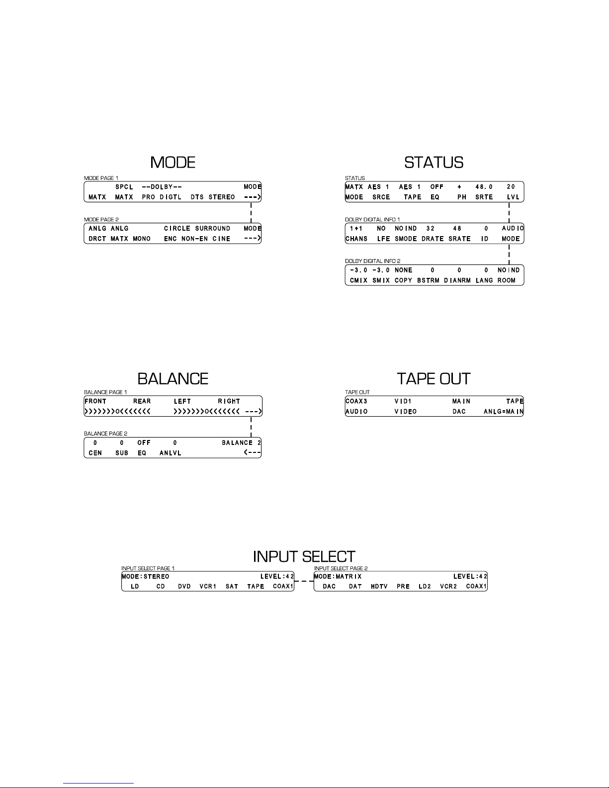
Figure 12 - Mode, Status, Balance, Tape Out Menus and Input Select Pages................................................................. 12
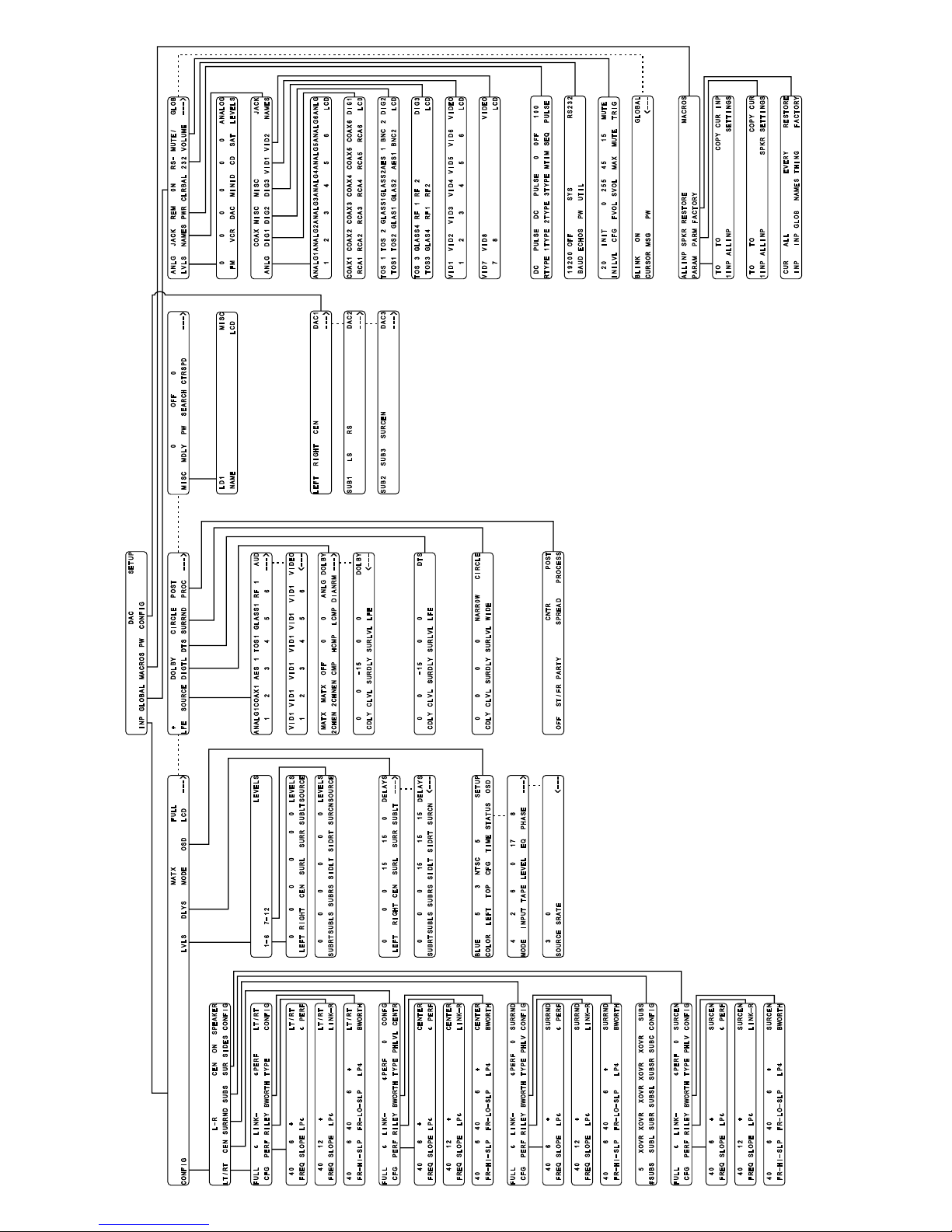
Figure 13 - Setup Menus and Pages.................................................................................................................................13
Figure 14 - Front Panel Display of the current INPUT SELECT page............................................................................... 40
Figure 15 - Front Panel Display of the SETUP/INP
Figure 16 - Front Panel Display of the MODE
Figure 17 - Front Panel Display of the MODE
Figure 18 - Front Panel Display of the TAPE OUT Menu..................................................................................................46
Figure 19 - Front Panel Display of the SETUP Menu........................................................................................................48
Figure 20 - Front Panel Display of the SETUP/Assign Password Display........................................................................48
Figure 21 - Front Panel Display of the SETUP/INPUT page 1 Submenu..........................................................................49
Figure 22 - Menu Map of SETUP/INP
Figure 23 - Front Panel Display of the Speaker Configuration Submenu.........................................................................50
Figure 24 - Front Panel Display of the Subs Configuration Submenu...............................................................................50
Figure 25 - Menu Map of SETUP/INP
Figure 26 - Front Panel Display of the Front left/Right Speaker Configuration Submenu................................................. 53
Figure 27 - Front Panel Display of the SETUP/INP/CONFIG/LT/RT/φPERF Sub Menu ...................................................53
Figure 28 - Front Panel Display of the SETUP/INP/CONFIG/LT/RT/Link-R Sub Menu....................................................54
Figure 29 - Front Panel Display of the SETUP/INP/CONFIG/LT/RT/BWORTH Sub Menu............................................... 54
Figure 30 - Front Panel Display of the SETUP/INP/CONFIG/CENTER Sub Menu...........................................................55
Figure 31 - Front Panel Display of the SETUP/INP/CONFIG/L-R SURRND Sub Menu....................................................56
Figure 32 - Front Panel Display of the SETUP/INP/LVLS/Channel Choice Sub Menu.....................................................56
Figure 33 - Front Panel Display of the SETUP/INP/LVLS 1-6 Sub Menu.........................................................................56
Figure 34 - Front Panel Display of the SETUP/INP/LVLS 7-12 Sub Menu.......................................................................57
Figure 35 - Front Panel Display of the SETUP/INP/DELAYS 1 Sub Menu .......................................................................58
Figure 36 - Front Panel Display of the SETUP/INP/DELAYS 2 Sub Menu .......................................................................58
Figure 37 - Rear Delay Settings........................................................................................................................................ 58
Figure 38 - Front Panel Display of the SETUP/INP/OSD Sub Menu.................................................................................59
Figure 39 - Front Panel Display of the SETUP/INP/OSD/STATUS 1 Sub Menu............................................................... 59
Figure 40 - Menu Map of SETUP/INP
Figure 41 - Front Panel Display of the SETUP/INP
Figure 42 - Front Panel Display of the SETUP/INP
Figure 43 - Front Panel Display of the SETUP/INP
Figure 44 - Front Panel Display of the SETUP/INP
Figure 45 - Front Panel Display of the SETUP/INP
Figure 46 - Front Panel Display of the SETUP/INP
Figure 47 - Front Panel Display of the SETUP/INP
Figure 48 - Menu Map of SETUP/INP
Figure 49 - Front Panel Display of the SETUP/INP
Figure 50 - Front Panel Display of the SETUP/INP
Figure 51 - Front Panel Display of the SETUP/GLOBAL
Figure 52 - Front Panel Display of the SETUP/GLOBAL/ANLG LVLS Sub Menu............................................................. 66
Figure 53 - Front Panel Display of the SETUP/GLOBAL/JACK NAMES Sub Menu.........................................................67
Figure 54 - Front Panel Display of the SETUP/GLOBAL/REMPWR Sub Menu................................................................67
Figure 55 - Front Panel Display of the SETUP/GLOBAL/RS232 Sub Menu.....................................................................68
Figure 56 - Front Panel Display of the SETUP/GLOBAL/MUTE-VOLUME Sub Menu...................................................... 69
Figure 57 - Front Panel Display of the SETUP/GLOBAL
Figure 58 - Front Panel Display of the SETUP/MACROS Sub Menu................................................................................ 70
Figure 59 - Front Panel Display of the SETUP/MACROS/RESTORE FACTORY Sub Menu............................................ 71
Figure 60 - Front Panel Display of the BALANCE
Figure 61 - Front Panel Display of the BALANCE
Figure 62 - Front Panel Display of the STATUS Display...................................................................................................73
Figure 63 - Front Panel Display of the STATUS/Dolby Digital
Figure 64 - Front Panel Display of the STATUS/Dolby Digital
Figure 65 - Remote Control Layout...................................................................................................................................76
Figure 66 - Video Display of the INPUT SELECT
Figure 67 - Video Display of the STATUS Display............................................................................................................ 79
Page 1
Page 1
Page 2
Page 3
Page 1
Page 2
/CONFIG.................................................................................................... 49
/CONFIG/LT/RT......................................................................................... 51
................................................................................................................... 60
................................................................................................................... 65
Page 1
Page 2
Page 1
/SOURCE/AUD page............................................................. 42
page 2
Menu.............................................................................................43
Menu.............................................................................................44
Sub Menu............................................................................. 60
Page 2
/SOURCE/AUD Sub Menu....................................................61
Page 2
/DOLBY DIGITAL
Page 2
/DOLBY DIGITAL
Page 2
/DTS Sub Menu..................................................................... 63
Page 2
/CIRCLE SURRND Sub Menu............................................... 64
Page 2
/POST PROCESS Sub Menu................................................ 64
Page 2
Sub Menu............................................................................. 65
Page 3
/MISC Sub Menu....................................................................65
page 3
/ Sub Menu.................................................................... 66
page 1
Sub Menu..................................................................... 70
page 2
Menu.......................................................................................72
Menu.......................................................................................72
Display.................................................................73
Page 1
Display.................................................................74
Page 2
Menu....................................................................................... 77
Sub Menu..................................... 62
Page 1
Sub Menu..................................... 63
Page 2
ix

Figure 68A - Video Display of the First Dolby Digital Status Page.................................................................................... 79
Figure 68B - Video Display of the Second Dolby Digital Status Page...............................................................................79
Figure 69A - Video Display of the MODE
Figure 69B - Video Display of the MODE
Figure 70A - Video Display of the TAPE OUT Menu with Optional Tape Out DAC installed and set to MAIN.................. 81
Figure 70B - Video Display of the TAPE OUT Menu with Optional Tape Out DAC installed and set to TAPE.................81
Figure 71 - Video Display of the SETUP Menu................................................................................................................. 83
Figure 72 - Video Display of the SETUP Password Page................................................................................................. 83
Figure 73 - Video Display of the SETUP/INPUT
Figure 74 - Video Display of the SETUP/INPUT
Figure 75 - Video Display of the SETUP/ INPUT
Figure 76 - Video Display of the SETUP/INPUT
Figure 77 - Video Display of the SETUP/INPUT
Figure 78 - Video Display of the SETUP/INPUT
Figure 79 - Video Display of the SETUP/INPUT
Figure 80 - Video Display of the SETUP/ INPUT/LEVELS 1-6 Sub Menu........................................................................87
Figure 81 - Video Display of the SETUP/INPUT/LEVELS 7-12 Sub Menu.......................................................................87
Figure 82 - Video Display of the SETUP/INPUT/DELAYS 1 Sub Menu............................................................................ 87
Figure 83 - Video Display of the SETUP/INPUT/DELAYS 2 Sub Menu............................................................................ 88
Figure 84 - Video Display of the SETUP/INPUT
Figure 85 - Video Display of the SETUP/INPUT/OSD/STATUS page 1 Setup Sub Menu................................................ 89
Figure 86 - Video Display of the SETUP/INPUT
Figure 87 - Video Display of the SETUP/INPUT
Figure 88 - Video Display of the SETUP/INPUT
Figure 89 - Video Display of the SETUP/INPUT
Figure 90 - Video Display of the SETUP/INPUT
Figure 91 - Video Display of the SETUP/INPUT
Figure 92 - Video Display of the SETUP/INPUT
Figure 93 - Video Display of the SETUP/GLOBAL
Figure 94 - Video Display of the SETUP/ANALOG INPUT LEVELS Sub Menu................................................................94
Figure 95 - Video Display of the SETUP/ INPUT/JACK NAMES Sub Menu.....................................................................94
Figure 96 - Video Display of the SETUP/GLOBAL/REMOTE POWER Sub Menu............................................................ 95
Figure 97 - Video Display of the SETUP/GLOBAL/RS232 Sub Menu..............................................................................95
Figure 98 - Video Display of the SETUP/GLOBAL/MUTE-VOLUME Sub Menu............................................................... 96
Figure 99 - Video Display of the SETUP/GLOBAL
Figure 100 - Video Display of the SETUP/MACROS Sub Menu.......................................................................................97
Figure 101 - Video Display of the SETUP/MACROS/RESTORE FACTORY Sub Menu................................................... 98
Figure 102A - Video Display of the BALANCE
Figure 102B - Video Display of the BALANCE
Figure 103 - Examples of Typical Input and Tape Out Connections............................................................................... 103
Figure 104 - Recommended Output Wiring Diagram Using 12 Single-Ended channels................................................. 103
Figure 105 - Recommended Speaker Placement for Six Channel Configuration........................................................... 104
Figure 106 - Recommended Speaker Placement for Twelve Channel Configuration..................................................... 104
Figure 107 - Recommended Output Wiring Diagram Using 12 channels (Six Balanced and Six Single-Ended)...........105
Figure 108 - Recommended Output Wiring Diagram Using 8 balanced Xtreme channels............................................. 105
Figure 109 Figure 110 -
Wiri ng diagram for the Casablanca II Digital Output board and a 2 Channel External Volume Control uni t
Wiri ng diagram for the Casablanca II Digital Output board and a 6 Channel External Volume Control uni t
Menu....................................................................................................80
Page 1
Menu....................................................................................................80
Page 2
Sub Menu.................................................................................. 84
Page 1
/SPEAKER CONFIGURATION Sub Menu................................. 84
Page 1
page 1
page 1
Page 1
page 1
Page 3
Page 2
Page 2
Page 2
Page 2
Page 2
Page 2
Page 3
Page 1
Page 2
/CONFIG/LEFT/RIGHT Configuration Sub Menu......................84
Page 1
/SPEAKER CONFIG/ CENTER Sub Menu................................. 85
/CONFIG/SURROUND CONFIGURATION Sub Menu............... 85
/CONFIG/SUB CONFIGURATION Sub Menu............................86
/CONFIG/SURROUND CENTER Sub Menu.............................. 86
/ON-SCREEN DISPLAY Sub Menu...........................................88
Sub Menu.................................................................................. 89
/DOLBY DIGITAL
/DOLBY DIGITAL
/DTS Sub Menu..........................................................................91
/CIRCLE SURROUND Sub Menu.............................................. 92
/POST PROCESS Sub Menu.....................................................92
Sub Menu.................................................................................. 93
Sub Menu.............................................................................. 94
Page 1
Sub Menu.............................................................................. 97
Page 2
Menu..........................................................................................100
Menu..........................................................................................100
Sub Menu .........................................90
Page 1
Sub Menu .........................................91
Page 2
......... 106
......... 107
List of Tables
Table 1 - Glossary of Terms and Abbreviations..................................................................................................................3
Table 2 - Available configuration settings for front L/R speaker Phase Perfect crossover................................................53
Table 3 - Available configuration settings for front L/R speaker Linkwitz-Riley crossover................................................54
Table 4 - Available configuration settings for front L/R speaker Butterworth crossover.................................................... 54
Table 5 - Source to Output Routing for Speaker Level Configuration............................................................................... 57
x

INTRODUCTION
Welcome to a new world of possibilities. Casablanca II is by far the most advanced surround sound
processor/home theater controller available today. It offers the advantages of Theta’s legendary mastery in
digital signal processing and sound quality unapproachable by any other equipment.
Getting to know your Casablanca II
Despite Casablanca II’s great technical sophistic ation, we believe in making it as easy as possible for you to
use. We think you’ll enjoy the intuitive way the Casablanca II works. Rather than offer a frustrating
bewilderment of little used functions in constant view, vying for your attention, Casablanca II is structured
systematically by function.
The “user interfac e” is bas ed on simple logic. For exam ple, when a func tion button is pressed, you can make
changes within its menu(s) and pres s the sam e function button again to ex it that function. (The sam e button
that got you in gets you back out).
This Casablanca II has been put thr ough a rigorous and unique testing procedur e that insures that it will last
for many years with minimal service requirements. This procedure includes the following:
• All assembled circuit boar ds are given a thorough visual inspection and are then tested in a benchreference Casablanca II.
• The tested assem bled circuit boards are then installed in a new Casablanca II and the whole unit is
tested for every function and parameter.
• The unit is put on a burn-in torture rack for 100 hours to test for any possible component failures.
• The Casablanca II is tested on an audio analyzer for all pertinent parameters.
• The Casablanca II is put through a final bench test wherein every possible feature, mode and
parameter is checked.
• The unit has all remaining chassis components installed and then undergoes a complete visual
inspection, which assures that all Casablanca II’s meet visual specifications.
• The unit is then put through a critical listening test.
Burn In Time
This unit has a break in per iod of about 1 week during which continuous im provem ent in s ound quality will be
observed. It is recomm ended that m usic be played continuously through the unit during this time to expedite
the break in period.
1

IMPORTANT NOTICE
I. Due to the computer- based c irc uitr y used in Theta produc ts, it is imperative that the Casablanca II be
connected to a ground via its three wire AC power cord. It is impor tant that the AC power outlet,
which the Casablanca II is plugged into, is actually grounded. Failure to do so will severely
compromise the performance, reliability and safety of use of the Casablanca II.
II. It is also im portant to prevent contact with static electric ity when connecting other components and
cables to the Casablanca II. When connecting cables, simply place one hand on top of the
Casablanca II and then grasp the metal “bar rel” of the cable with the other hand and plug (unplug)
the cable into (from) the appropriate jack on the Casablanca II.
III. The Casablanca II, as with all electronic equipm ent, is s us ceptible to s tatic dis char ges . Resetting the
unit may be required if anomalies occur af ter r eceiving a s tatic dis c harge. In this c ase , put the unit in
standby and turn off the rear panel power switch for 2 minutes, and then turn it on again.
IV. Ventilation is an im portant issue when plac ing the Casablanca II in a system. Make c ertain that the
Casablanca II is placed in a well-ventilated area or rack unit.
V. Please take note that some powerline conditioner s defeat the AC power ground on their outlets. If
the intention is to plug the Casablanca II into a line conditioner, check with your dealer to make
certain that the particular conditioner that is intended for use DOES NOT DEFEAT THE AC
GROUND on its AC outlets.
VI. DO NOT remove any cover panels from the Casablanca II, as there are no user serviceable
components inside. Refer servicing and updating to qualified service personnel only.
VII. Should the Casablanca II need to be reset, it must be put in standby first via the front panel power
button. Then the rear panel power switch is to be turned off for at least 2 minutes.
VIII. The Casablanca II c an be susceptible to excessive RF. End caps in all unus ed inputs will improve
the sound quality and may reduce the susceptibility to RF induced anomalies.
Reference Manual Conventions
For clarity purposes, references to buttons, LED’s and display parameters will be shown in bold capital letters.
All functions to be performed from, and in ref er ence to the front panel of the Casablanca II will be found in the
front section of this m anual, whereas all functions to be perf orm ed using the hand held rem ote and/or viewed
on a video monitor will be found in the back, or last part of this manual.
2

Glossary of Terms and Abbreviations
TERM DEFINITION
AES/EBU (Audio Engineering Society) / (European
Broadcasters Union)
Analog-to-Digital Converter A device that converts analog signals into a digital format. Once
Balanced Audio Signals Signals that are carried on three-conductor cables, with two of the
Center Spread A proprietary Theta Digital process whereby the front center speaker
dB Decibel, a relative unit of loudness.
Dolby 3 Stereo The Dolby 3 Stereo mode reproduces sound using only the 3 front
Digital-to-Analog Converter A device that converts digital signals into an analog format.
Hz (Hertz) A unit of frequency.
IR Infrared. A method of wireless transmission of data.
LFE Low Frequency Effect. Commonly a discrete audio track designated for
mS Millisecond, or 1\1000 of a second.
Oversampling The process of taking more samples than is required in order to more
Phantom Center Mode The Phantom setting for the center speaker redirects the center channel
Phantom Surround Mode The Phantom setting for the surround speakers is intended to be used
Sampling Rate The rate at which an analog (real world) signal is converted into digital
S/PDIF Interface (Sony/Phillips Digital Interface
format)
TRS Tip, Ring, Sleeve. Names of the 3 connecting elements of a stereo
Unbalanced Audio Signals (AKA single-ended) Signals that are carried on two-conductor cables, one “hot”, or signal,
Xover Abbreviation for the word ‘Crossover’.
Table 1 - Glossary of Terms and Abbreviations
A three wire balanced digital audio standard. This interface uses a 3-pin
XLR type connector and allows for data communication between digital
audio equipment.
encoded, all audio is stored or processed as a series of numbers rather
than as the audio itself.
conductors carrying the same signal 180° out of phase and the third as
ground. Balanced connections usually cost more than unbalanced
connections, but are less susceptible to picking up hum and prevent
interference with low-level signals.
signal can be incrementally spread evenly between the front left and
right speakers.
channels, and is intended to be used either before surround speakers
are installed, or for programs that might benefit from deriving a center
channel output, but where the quality of the surround output is
unsatisfactory.
a sub woofer.
accurately reconstruct a digitized signal for playback in the analog
domain.
signal equally to the front left and right outputs, thus creating an illusion
of a center speaker. This mode is intended to be used when no center
speaker is present.
when no surround speakers are present in the system. With this setting
active, the surround information is added to the front channels. If the
current mode is Dolby Pro Logic, the Casablanca II will automatically
decode in Dolby 3 Stereo.
numeric values.
A digital audio interconnection standard, developed jointly by Sony and
Phillips.
phono jack or plug.
and one ground.
3
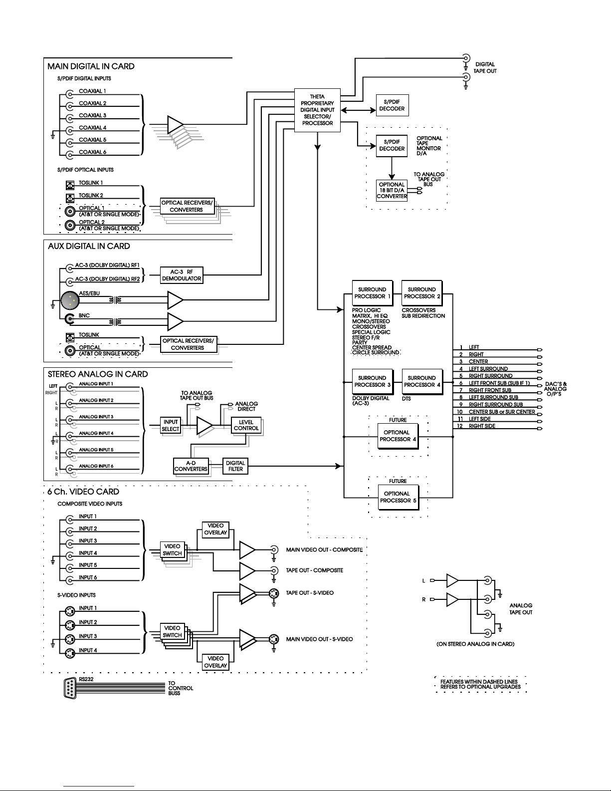
Casablanca II Block Diagram - Input Processing Sections
Figure 1 - Block Diagram of Input Processing Sections
4
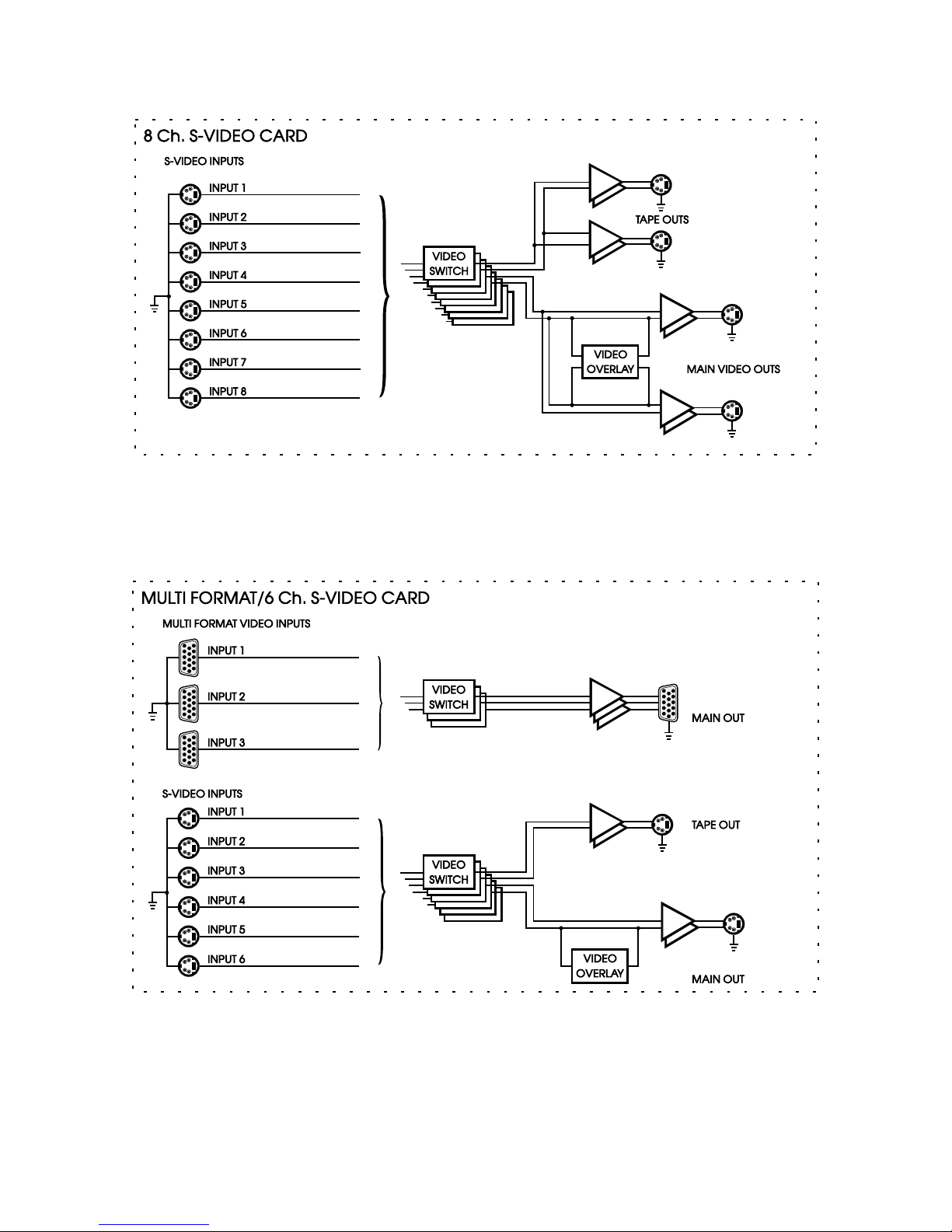
Casablanca II Block Diagram - Input Processing Sections – Con’t
Figure 2a - Block Diagram of 8 S-Video Switching Card
Figure 2b - Block Diagram of Multi Format/6 S-Video Switching Card
5
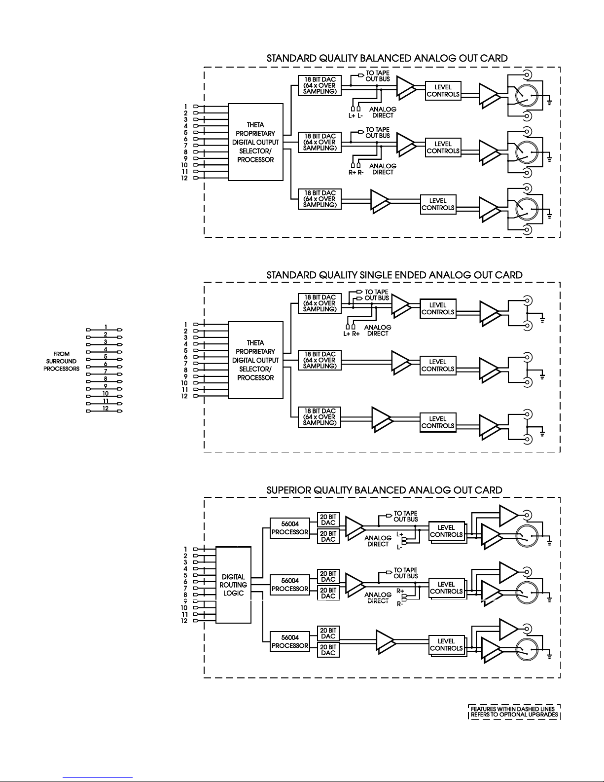
Casablanca II Block Diagram - DAC and Analog Out Sections
Figure 3 - Block Diagram of DAC and Analog Outputs
6

Casablanca II Block Diagram - DAC and Analog Out Sections – Con’t
Figure 4 - Block Diagram of Xtreme 4 Channel DAC board
Figure 5 - Block Diagram of Digital Output board, showing all options
7
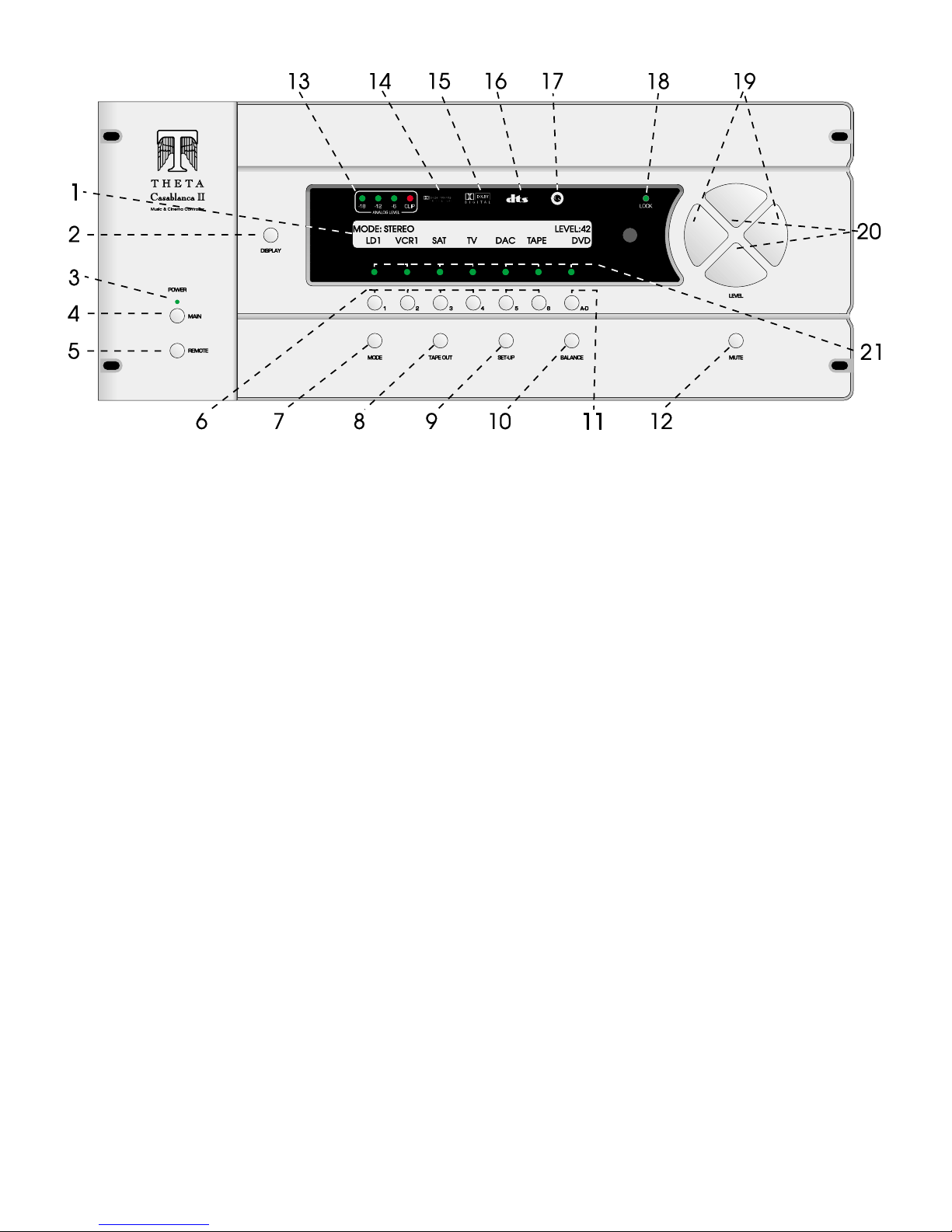
Front Panel Layout
Figure 6 - Front Panel Layout
1. 40 character by 2 row amber back lit liquid crystal display (
DISPLAY
2.
POWER
3.
MAIN POWER
4.
button. Temporarily overrides the LCD brightness display setting in the
LED. Lights when the Casablanca is in standby mode.
button. After the rear panel
MAIN POWER
standby mode. The LCD will display the last selected
Casablanca into standby mode and the LED above the front panel
REMOTE POWER
5.
button. Activates/deactivates the
6. Buttons 1 through 6. Used to select a desired input on
The LED over the button lights when the button is pressed. These buttons are referred to as the
7.
8.
9.
MODE
button. Activates the
TAPE OUT
SET-UP
button. Used for routing audio and video
button. Used for setting speaker configurations/levels/delays, analog input levels, naming inputs, setting the display
MODE
select menus for the currently selected input.
& remote power jack time-out delays, selecting between NTSC and PAL video sources and accessing additional surround
parameters, and all other
BALANCE
10.
different program characteristics.
A-D
11.
MUTE
12.
ANALOG LEVEL
13.
Dolby Pro Logic
14.
The
Dolby Digital
15.
DTS
16.
Circle Surround
17.
LOCK
18.
LEVEL LEFT
19.
button. Sets temporary speaker balance configurations, shelf EQ, and analog input levels to compensate for
button. Sequences through input jacks mapped (assigned) to the active
button. Mutes/unmutes all audio outputs with the exception of the
display. Shows input level, in dB, of currently selected analog input.
indicator. Lights when the Dolby Pro Logic feature is installed only. If Dolby Digital (AC-3) is also installed,
Dolby Pro Logic
indicator. Lights when Dolby Digital is installed. It will go out when the display is turned off.
indicator. Lights when the DTS feature is installed. It will go out when the display is turned off.
Indicator. Lights when the Circle Surround feature is installed. It will go out when the display is turned off.
light. Lights when a valid digital signal is detected on the selected input.
and
the master volume within submenus when the
toggle between the 2 input select pages, shifts to the next character when editing names.
LEVEL UP
20.
modes, and shifts
21. 1 through 6 LED indicators. Light when buttons 1 through 6 are selected.
and
DOWN
SETUP
functions.
indicator will never be lit. It will go out when the display is turned off.
RIGHT
buttons. Shifts audio balance to the left and right when the
LEVEL UP/DOWN
buttons. Increases/decreases master volume. Also used to increment/decrement values in most edit
FRONT/REAR
audio balance in
BALANCE
LCD) or blue vacuum tube display (VFD).
SETUP/INP
switch is turned on press the front panel
INPUT SELECT
POWER
REMOTE POWER
INPUT SELECT
INPUT
signals to the
menu. Pressing this button again will place the
button will light.
jack on the rear panel.
pages, or parameter to change when in a sub menu.
TAPE OUT
jacks.
INPUT SELECT
TAPE OUT
jacks.
BALANCE
buttons are to be used for parameter value editing, used to
submenu.
page 1 submenu.
POWER
INPUT SELECT
button to exit the
buttons.
button.
function is selected, adjusts
8
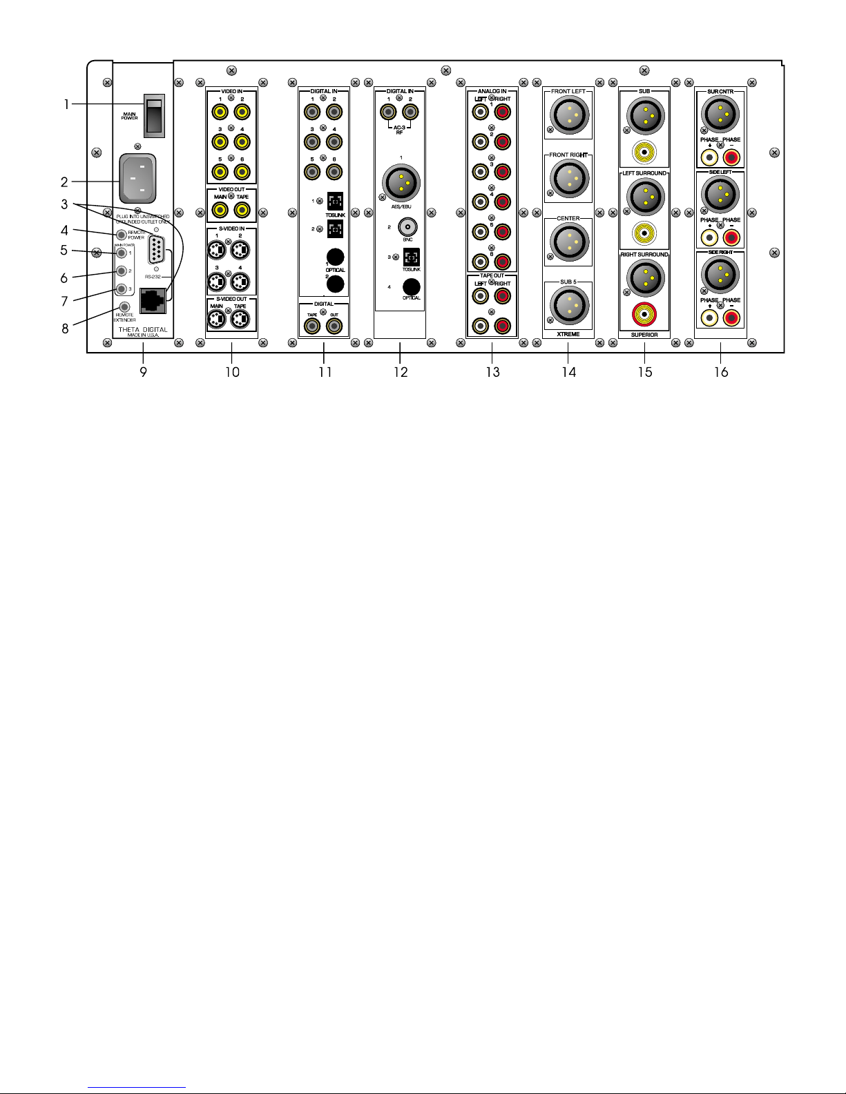
Rear Panel Layout
Main Power Sw itch .
1.
Master power switch. Disconnects AC to all circ uits. It is recomm ended that this be left ON
Figure 7 - Rear Panel Layout
at all times during regular use with the exception of whenever cables are connected/disc onnec ted or when the unit
is not going to be used for an extended period of time.
AC Power
2.
RS232
3.
the Main Digital Input board.
Remote Power
4.
again.
Main Power 1
5.
Power jacks can output a 12V pulse (variable duration) or 12VDC.
Main Power 2
6.
the time value that is stored in the
the front panel
Main Power 3
7.
represents the time value that is stored in the
deactivated when the front panel
Remote Extender
8.
phone jack. (its signal must be demodulated). Please refer to Appendix C on page 108 for additional information.
Power Supply Module
9.
Video Card
10.
connector: 3 wire, IEC 320 connector with an EMI filter.
DB9 and RJ45 connectors. A Casablanca upgraded to a Casablanc a II has only the DB9 connector, on
jack. Activated/deactivated when associated front panel or remote button is pressed/pressed
jack. Activated/deactivated when front panel
jack. Activated when front panel
POWER
SET-UP/GLOBAL/REM PWR/M T IM
POWER
jack. Activated when front panel
button is pressed again (putting the Casablanca in Standby mode).
POWER
SET-UP/GLOBAL/REM PWR/MTIM
POWER
button is pressed again (putting the Casablanca in Standby mode).
POWER
button is pressed/pressed again. All Main
button is pressed once, plus x sec onds. X represents
parameter. This j ack is deac tivated when
button is pressed once, plus two times x seconds. X
parameter. This jack is
jack. An externally mounted ( remote) Infrared (IR) receiver plugs into this m iniature stereo
.
. This optional card , necessary for on-screen display, provides six com posite RCA and four S-Video
inputs, all assignable to any input select button. Video inputs are routed to the video tape output jack using the
TAPE OUT
button. Only S-Video input signals can be present at the S-Video
Main
and/or
Tape
outputs. Another
option for this slot is a video card containing 8 S-Video inputs with 2 main and 2 tape outs. There are no
composite video jacks on this alternate optional card.
Main Digital Input
11.
card. Six Coaxial (RCA) and two TosLink inputs are provided for digital audio signals in the
S/PDIF format at 32K, 44.1K 48K or 96KHz sam pling rates. There are two open spaces provided for optional
AT&T and/or Theta Single Mode Laserlinque optical input modules. There are two RCA digital Tape Out
connectors on this card whose digital source can be selected in the
Auxiliary Digital Input
12.
card. This card provides two RCA Dolby Digital (AC-3) RF inputs, one AES/EBU
TAPE OUT
menu.
(balanced XLR) input, one BNC and one TosLink input. Additionally there is one space provided for an optional
AT&T or Theta Single Mode optical input.
Analog Input
13.
card. Six stereo RCA inputs are provided f or any line level analog output devices such as VCR’s,
laserdisc, CD and DAT players, phono preamplifiers, external D/A converters, tape decks, AM/FM tuners, etc.
There are two pairs of analog tape outs for r ecording purposes , whose source c an be selected in the
menu.
TAPE OUT
9
14. First
Analog Output
card. Configured as a 2 channel D/A converter /preamp there would be a 2 channel (L & R)
superior quality balanced card loaded in this slot. Configured as a s urround proc essor , this s lot could contain one
of the following: A four channel Xtrem e quality DAC (pictured), a six channel standard quality single ended D/A
card (left, right, center, sub, left surround and right surround) or a three channel balanced card (left, right and
center). A balanced card can be either standard or superior quality. All 3 channel balanced cards also have
single ended outputs; the standard card has a plus and m inus single ended output for eac h channel whereas the
superior quality balanced card is equipped with one gold plated single ended output jack on each c hannel. The
Xtreme card does not have s ingle-ended outputs. The c hannel sets that can be r outed to an Xtreme card (in any
DAC slot) are listed in the specifications section of this manual.
15. Second
Analog Output
card. T his slot could contain one of the following options: A four c hannel Xtrem e quality
DAC card; a three channel standard quality balanced card, a three channel superior quality balanced card
(pictured) or a six c hannel single- ended standar d quality card. If only two 3 channel balanced analog output cards
are installed, this slot would typically contain outputs for sub, left surround and right surround channels.
16. Third
Analog Output
card. T his slot could contain either a four channel balanced Xtrem e quality card; a three
channel standard quality balanced card (pictured), a three channel s uper ior quality balanced card, or a six channel
single-ended standard quality card. If it is a balanced card containing additional Sub channels, it must
same quality as the second card.
be the
* * *
A Digital Output card can be installed in any available slot. This card can have 6 or 12 digital output channels and
comes with or without a center analog output c hannel. Additionally it can have an optional optical output installed on it
for the front left and right channels. This output can be either an AT&T or Theta Single Mode module.
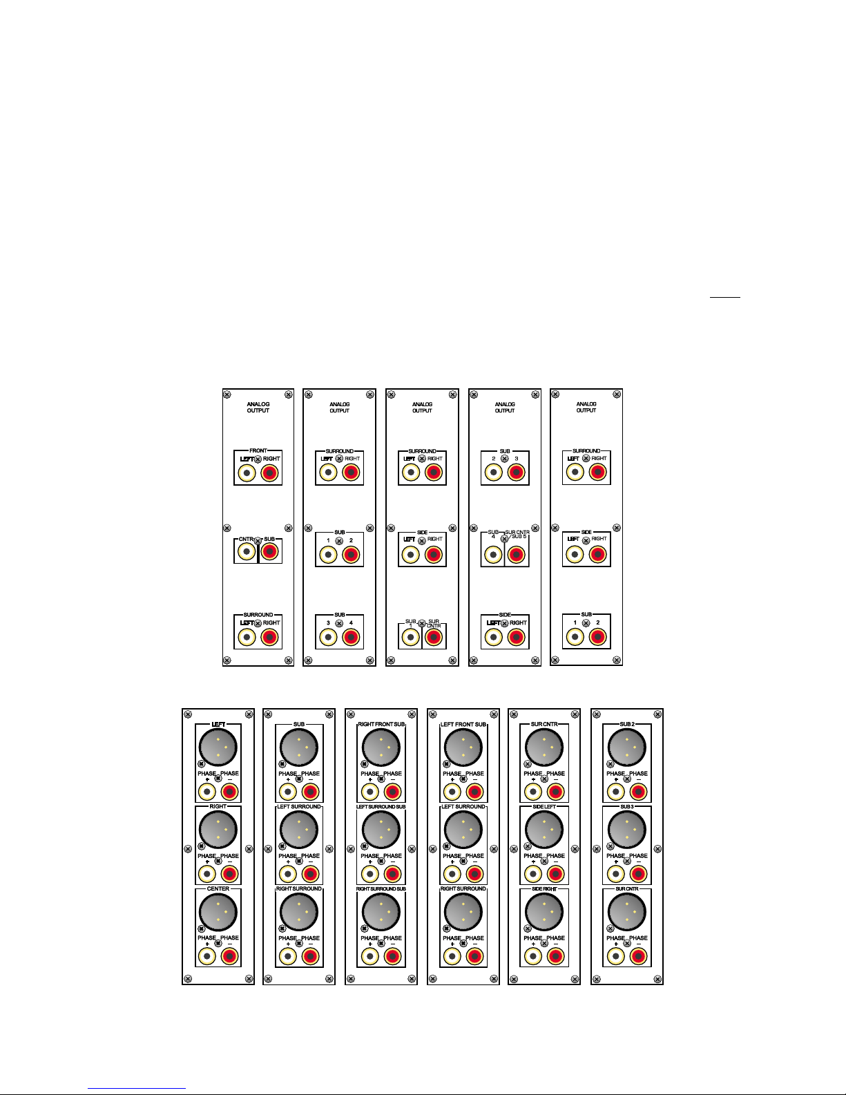
Figure 8 - All optional Single-Ended D/A Cards
Figure 9 - All optional Standard Balanced D/A Cards
10
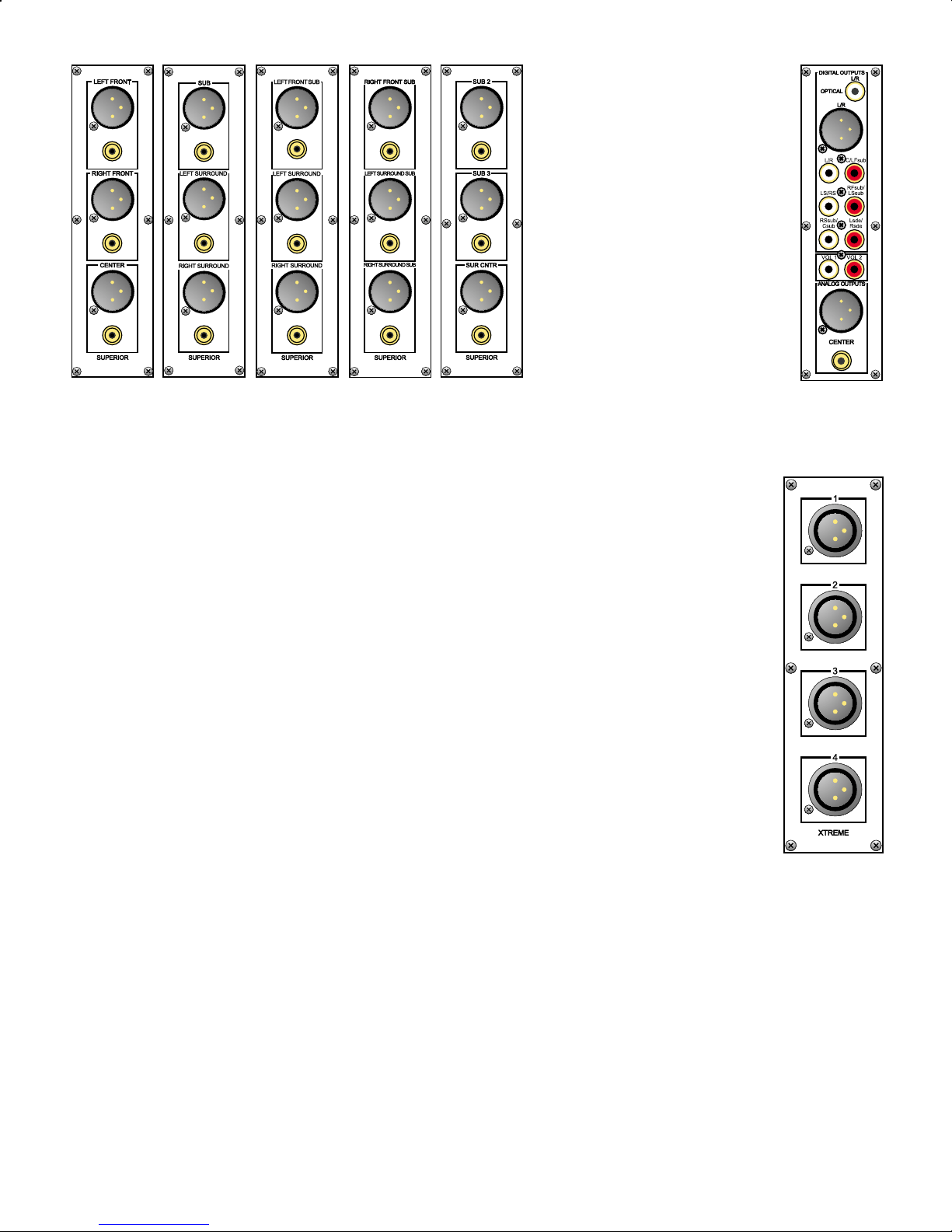
Figure 10 - All optional Superior D/A Cards and the Digital Output card with
Center Channel
Each Xtreme DAC card can have one of the following speaker sets (channels) assigned to them, regardless of which
DAC slot it (they) are installed to:
Front Left, Right, Center, Surround Center or Sub 5
Front Left, Right, Side Left, Right
Sub 1, Sub 2, Sub 3, Sub 4
Side Left, Right, Sub 3, Sub 4
Front Left, Right, Sub 1, Sub 2
Surround Left, Right, Sub 1, Sub 2
Surround Left, Right, Sub 2, Sub 3
Front Center, Sub 1, Sub 2, Sub 3
Front Center, Sub 1, Surround Left, Right
Front Left, Right, Surround Left, Right
Surround Left, Right, Side Left, Right
Front Left, Right, Center, Sub 1
Sub 1, Sub 2, Sub 3, Surround Center or Sub 5
Surround Left, Right, Center or Sub 5, Sub 1
Surround Left, Right, Center or Sub 5, Sub 2
Front Center, Surround Center or Sub 5, Surround Left, Right
Front Center, Surround Center or Sub 5, Side Left, Right
Sub 2, Sub 3, Sub 4, Surround Center or Sub 5
Figure 11 - Xtreme DAC
Note: In figure 11, each output is shown with a number 1-4. Channel labels are available to better identify each output.
11
Menu Maps
Function Menus and Pages
Input Select Pages
Figure 12 - Mode, Status, Balance, Tape Out Menus and Input Select Pages
12
13
Setup Menus and Pages
Figure 13 - Setup Menus and Pages

Introduction to the User interface
WARNING !! : PLEASE READ FIRST!
In the
SETUP
SETUP/INPUT
input. The entire
and the
menu, the PW button allows the user to password protect the entire
page 3 sub menu, the PW button allows the user to password protect the currently selected
menu can be pass word protected via the PW button on the second
RS232
GLOBAL
sub menu can be password protec ted via the PW button in the
SET-UP
function. In the
GLOBAL
SETUP/GLOBAL/RS232
page
sub
menu. W hen any PW button is selected, a prompt will be displayed asking the user if they are sure they want to
change the current password (
or NO). If
YES
is selected, the current pass word will be displayed with the
YES
cursor blinking on the firs t character, prompting the end-user to change the curr ent password. The password
does not have to be changed at this point, the same num bers that ar e currently displayed can be entered, using
buttons 1-6 and/or
no password. Therefore, to remove a password, press
Please note that there are no passwords programmed into the Casablanca II when it is initially shipped.
PLEASE REMEMBER and/or WRITE DOWN YOUR PASSWORDS!
password protected areas will be denied!
The menu s ystem within the Casablanca II c onsists of 1 to 3 layers, with the exception of the
Some menus have multiple pages, which can be access ed simply by pressing the
of the
INPUT SELECT
. Pressing
A-D
A-D
menu, which uses the
enters a zero. A password containing at least one zero is null, meaning
at least once.
A-D
If it/they are forgotten, all access to
menu.
LEFT/RIGHT
SETUP
button, with the exception
A/D
buttons. When a menu has additional pages
associated with it, a right or left arrow will be displayed in the bottom right corner of the LCD. Please refer to
figures 1 and 1 for an overall view of all menus, sub menus and menu pages.
The
SETUP
parameters can be stored for each
SETUP/INPUT
are accessed in the two
sub menu.
Once a parameter is selected for editing, pressing the
storing it at the s ame time. O n any page, if the
value, they will adjust the master volume. Where the
parameter value, the
BALANCE
the
MODE
The function buttons are defined as the
menu contains a num ber of sub menus, organized by setup function. Since many configuration
INPUT SELECT
sub menus. Setup parameters that are not st ored individually for each
SETUP/GLOBAL
sub menus. All m acros can be executed via the
LEVEL UP/DOWN
LEVEL LEFT/RIGHT
buttons will adjust the master volum e, with the exception of the first
button (by input), they are accessed in one of the 3
INPUT SELECT
button
SETUP/MACROS
LEVEL UP/DOWN
buttons edits the param eter value,
buttons are not used for editing a param eter
LEVEL UP/DOWN
buttons are used for editing a
page and the pages where input selec t buttons and input jac ks ar e named. In a f ew cases, suc h as
and
POST PROCESS
menus, simply pressing the 1-6 buttons makes a selection.
MODE, TAPE OUT, SET-UP
, and
BALANCE
buttons. To exit a function
the same function button can be pr essed m ultiple tim es to exit, or another function button c an be pressed at any
time.
Before you begin
With all input options ins talled in a Casablanca II, there are 32 input jacks: 6 pairs of stereo analog audio, 14
digital audio, 2 AC-3 RF, 6 composite video and 4 S-video. If the optional 8 S-Video input card is installed, then
there will be 8 S-Video inputs and no composite video inputs. If the optional Multi Format/6 S-Video board in
installed, then there will be 3 Multi format video inputs and 6 S- video inputs. Each jack can be named. It is
recommended to f irst nam e each input jack that is to be used. (
on screen menus will exist when using the 15 pin multi format video output.
Each
INPUT SELECT
it. Input jacks should be m apped to
SELECT
LEVEL LEFT/RIGHT
button should also be named. There are a total of 12
When editing param eters for a given
SELECT
containing the desired parameter to change.
Note
button in the
: The order in which input jack s are assigned to an
button can have up to 6 audio, 6 compos ite and 6 S-video jack s mapped, or as signed to
INPUT SELECT
buttons after the applic able jack s are nam ed. The
buttons will toggle between these two pages of 6 inputs each.
INPUT SELECT
INPUT SELECT
page, then press
button, the user must firs t press the applicable
SETUP/GLOBAL/JACK NAMES
INPUT SELECT
SET-UP
and
INPUT SELECT
button determines the search order .
s on two pages. Pressing the
, then navigate to the menu
INPUT
Please refer to page 42 for additional inf ormation on source assignm ent (search order). W hen more than one
input jack is assigned to a single
INPUT SELECT
button, toggling the
button [when the
A-D
page is active in the front panel display] will select the next assigned input jack – both audio and video.
). No OSD, or
INPUT
INPUT
INPUT SELECT
14
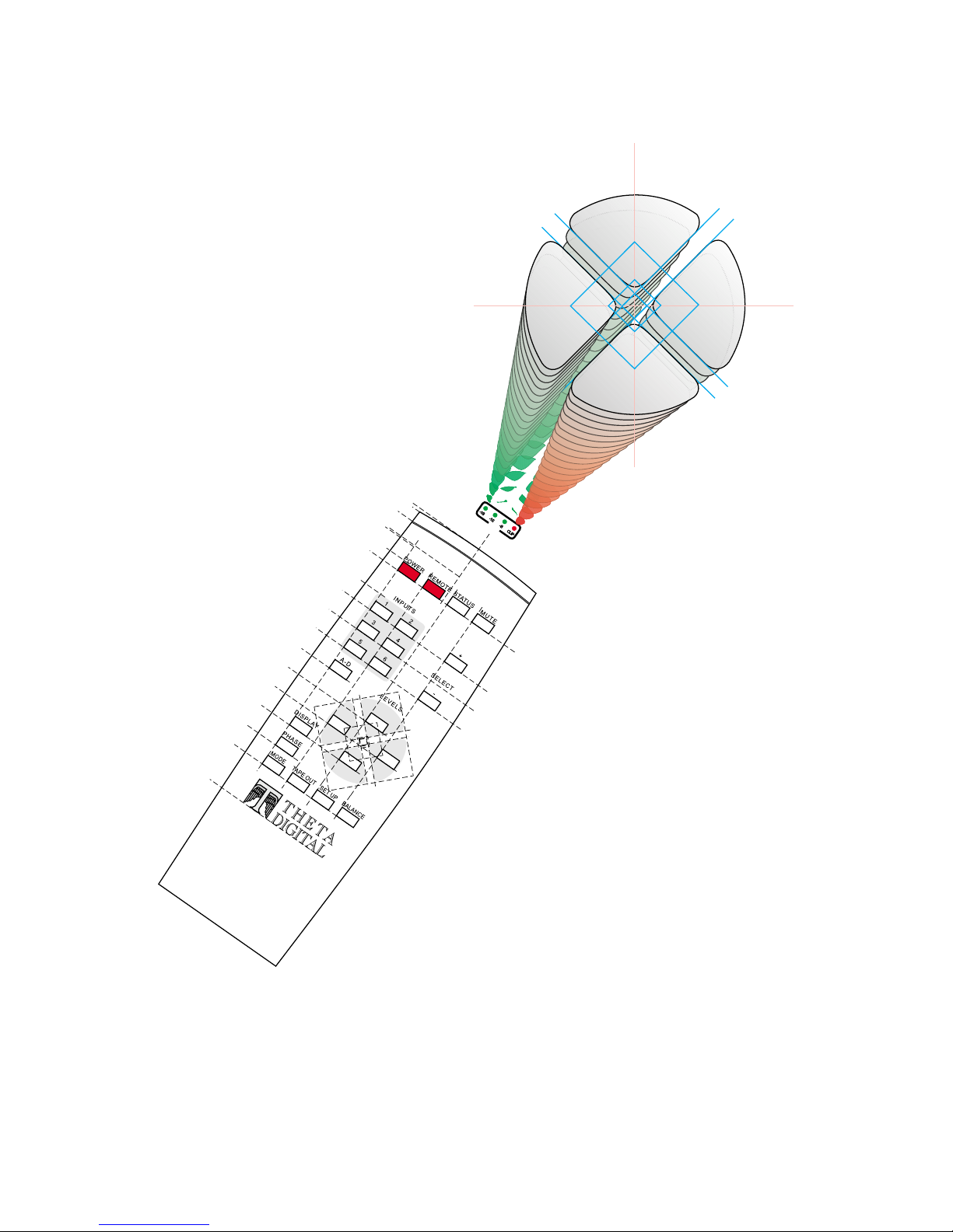
STEP-BY-STEP SETUP GUIDE
15
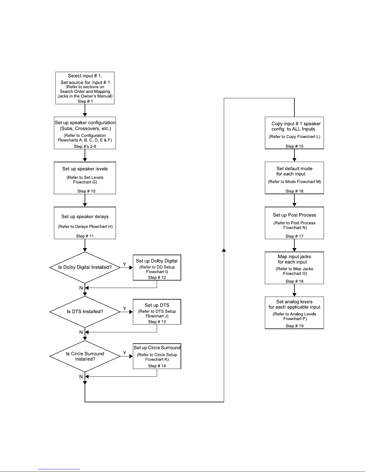
Casablanca II Overall Setup Procedure Flowchart
This single flowchart shows the user all steps required to set up the Casablanca II, to achieve the best sonic results
possible. Instructions and detailed flowcharts for each step are contained on the following pages.
16
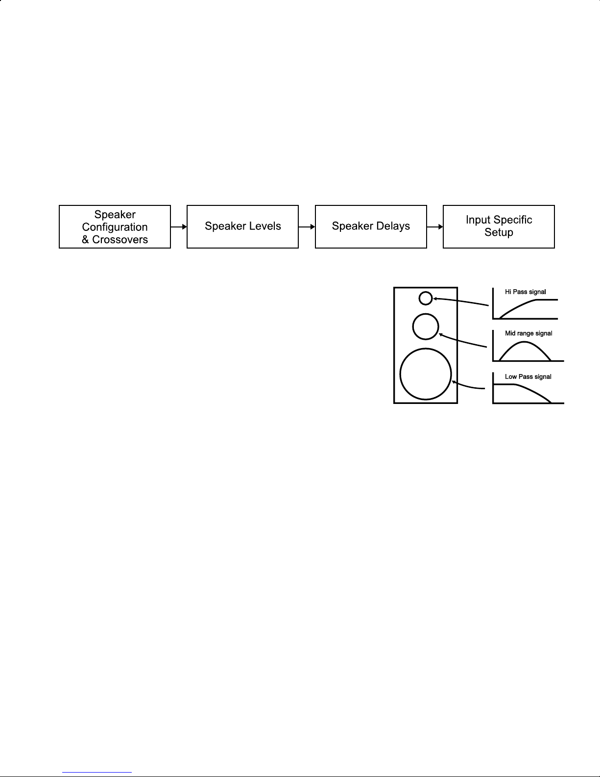
Step by Step Speaker Configuration
Casablanca II contains a com prehensive set of speak er configuration settings. T hese settings are believed to be the
most complete ever offered in a home theater component and should allow any speaker to perform optimally
regardless of speak er type. It is important to bear in mind that the following procedur e is merely a guideline and that
room acoustics, speaker design/quality, music/film type, and personal preferences all have a part in these settings.
Please note that the menu and parameter nam es desc ribed herein are the ones shown on the fr ont panel LCD and not
the OSD (On Screen Display). Using the Setup menu map diagram on page 13 in this manual, is recommended.
There are four major steps to be taken in setting up your Casablanca II. In recommended sequence, they are:
Speaker Configuration & Crossovers:
blending of main and subwoofer signals. Enables all speakers present in the system.
Individual speaker levels:
Delays:
Input Specific Setup:
compensates for different speaker distances from the listening position.
compensate for different speaker and amplifier efficiencies.
All parameters that are specific to an individual input select button are then programmed.
permits proper signal routing internally in the Casablanca II and proper
Each step plays a pivotal role in the overall sonic result and should receive equal attention and care in adjustment.
Speaker Configuration & Crossovers
Crossovers are most com monly located in a speaker cabinet. T heir purpose
is to keep energy at certain frequencies from reaching specific speaker
elements (drivers), [e.g. k eeping unwanted bass energy from the tweeters
(see diagram at right).] Home theater applications use a crossover in the
surround processor to s end low pass infor m ation to a subwoofer and limit the
low pass information s ent to the m ain speak ers . The pur pose of this sec tion,
SPEAKER CONFIGURATION
, is to properly set up the Casablanca II’s
internal crossovers for optimal sound as well as enable all speak ers in the
system.
In this manual, a Speaker Set is defined as one or more speakers that are
manipulated via a common parameter. For example, the crossover
parameters f or both the front lef t and right speak ers are m anipulated in the front lef t/right conf iguration subm enu since
the desired effec t f or the lef t speaker is als o appr opriate f or the right. The other speaker ‘sets ’ in the Casablanc a II are
the [surround left and right], the [side left and right], the [center] and the [center surround]. T he speaker sets will be
delimited by [ ].
The full speaker configuration is stored separately for each of the 12 input s elect buttons. This procedure will guide the
user to set all configuration parameters for input # 1, and then copy these parameters to all other input select buttons.
In the Speaker configuration subm enu, buttons 1-5 will access additional menus to s etup a particular speak er or set of
speakers. Button 6 will turn on the side speak ers , if conf igured in the system . In each speak er set’s c onfigur ation sub
menu, pressing button # 5 will allow a change of the crossover type for that speaker set. There are three settings for
the crossover type. They are: "Phase Perfect"; "Butterworth"; and "Linkwitz-Riley". Each crossover type requires
different settings that are applicable to that type only. The Front [Left/Right], [Center], [L-R Surround] and [Center
Surround] speaker configuration submenus contain a separate setup submenu for each of the three crossover types. It
is recomm ended that each of the three cross over submenus be set up s imilarly for each speaker . The user can then
audition each crossover type to determine which sounds best for their system.
The following crossover type descriptions will help the user to better understand the sonic consequences and
advantages of each:
Phase Perfect
This is a term c oined for a type of crossover wherein the low pass portion is derived from the high pass. First, a high
pass Butterworth cros sover is performed. This gives two resulting signals: the high pass and the original, unaltered
signal. Then, the high pass s ignal is subtrac ted from the original input signal, res ulting in the low pass signal, which is
usually routed to the subwoofer. A positive attr ibute of this type of cros sover is that if the high and low pass signals are
added together, an exact replica of the original input signal results, thus the term "phase perfect". A potentially
negative attribute of this type of cros sover is that, due to phase relationships and vector mathematic s, higher order
filters (12, 18, 24 dB/octave) always produce 6dB/octave low pass slopes, in terms of electrical energy sent to the
subwoofer. The high pass portion will have the expected 6, 12, 18 or 24 dB /octave slope. Due to this phenomenon,
this type of crossover is best suited f or subwoofers that can operate linearly up to the 500 Hz range. Please consult
17
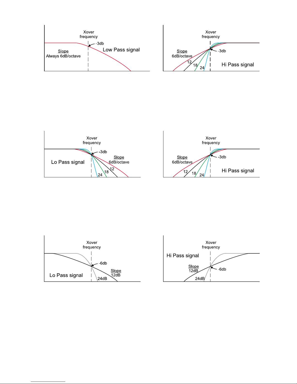
your dealer or subwoofer m anufac turer to deter m ine if this is suitable f or your particular subwoof er. If the s ubwoofer is
capable of handling this range, this is potentially the best sounding of Casablanca II's crossover types.
Phase Perfect Cross over Diagram
Butterworth
This is the most common type of crossover used in home theater, speakers and outboard electronic crossovers.
Separate high and low pass slopes and crossover frequencies may be set for speaker sets [Left/Right], [Center],
[Surround Left / Surround Right] and [Center Surround]. (T he [Sides] are derived from the L/R Surround channels and
therefore the conf iguration and crossover parameters for the sides are set in the L/R Surround sub menu). As with
Phase Perfect and Linkwitz-Riley crossovers, it is possible to invert the phase of the low pass for each of these speaker
sets. This allows precise tailor ing of the subwoofer response to the m ain speaker's response. A negative attribute of
this crossover type is that the high and low pass signals have different phase shifts from each other.
Butterworth Crossover Diagram
Linkwitz-Riley
This type of crossover, developed in 1976 by Siegfried Linkwitz and Russ Riley, eliminates some of the inherent
problems of Butterworth f ilters. Specifically, a Butterworth filter of 12, 18 or 24 dB/octave (or higher) slope exhibits
different phase shifts between the high and low pass outputs. A Linkwitz-Riley alignment solves this problem , as it
exhibits zero phase difference between outputs at all f requencies. Acoustically, this means that if the sound sources
are in proper tim e-alignment, a sm oother frequency response will be realized at the listening position. The Link witzRiley crossover is only applicable to slopes of 12 and 24 dB/octave. A proper Linkwitz-Riley crossover with a 12dB
slope should have the low pass portion inverted. This is done internally in the Casablanca II.
A note on crossovers
Casablanca II's complement of crossover options can at first appear daunting. Most surround sound processors offer a
simple selection to set their crossover s: Speaker Small or Speaker Lar ge. W hen set to s mall, nor mally a 12dB/octave
Butterworth crossover is performed at 80Hz. Oc casionally, it is a 24 dB/octave slope. This simple setting does not
take into account the huge variations in speak er design and room acoustics and more often than not results in nonoptimum per formance. W e have endeavored to offer this rich set of options with the aim of superior performance.
With this in mind, following are a few simple suggestions to make this process easier.
A note on home theater
There are a few comm on misconceptions about hom e theater and bass reproduction. Chief among them is that the
".1" or "LFE" channel normally contains most or all of the bass information. This is unequivocally false. The LFE
channel contains sound effec ts such as explosions, rumbling and the like. All other channels (left, center, right, left
surround, right surround) m ay contain an equal amount of bass, and of ten do. Their bass, however, tends to be more
Linkwitz-Riley Crossover Di agram
18

related to the soundtrack, vocal material or localized sources such as a drum beating behind the listener. This is
important to understand when setting up crossovers in the coming section.
Another misconception is that the c enter channel is "fill" and is minor in im portance. Again, this is false. The center
channel contains the lion's share of important information (particularly dialog) in the cinematic experience. It is
therefore critical that the center s peaker be of the highest quality possible and special attention be given to its mounting
and positioning.
* * *
Speaker Configuration & Crossovers – Con’t.
1) Select Input # 1.
Connect a digital sourc e to Coaxial Input 1 jac k and verify that the input jack m apping is c orrec t, i.e if the digital sour ce
is connected to the coax input jack # 1, press the
button until
A-D
COAX 1
appears in the LCD above it.
2) With Input button # 1 selected:
a) Go to the
b) Set
SUB CONFIG
#SUBS
to the number of sub woofers that are configured into the system.
c) If no subwoofer is present, set
submenu.
#SUBS
to 0. The subwoofer Full Range/Crossover setting has no effect
in this case.
: You will now be directed to set up crossovers as if a sub is present. There are some gener al rules that the
Note
Casablanca II follows in the special case of no subwoofers:
Case 1 - The front left/right speaker configuration is set to
If the center speaker is set to "crossover" its low pass signal will be sent to the left/right channels.
FULL
:
If the surround left/right speaker conf iguration is set to “crossover” its low pass signal will be sent to the front
left/right speakers only if the mode is Dolby Digital or DTS.
Case 2 – The surround left/right speaker configuration is set to
FULL
:
If the center surround speaker is set to “crossover” its low pass signal will be sent to the left/right surround
channels.
Case 3 - The front left/right configuration setting is
XOVER
or
FUL/LP
:
Any speaker that is set to c r oss over will los e its low pas s s ignal unless it is the f ront c enter and its low pass s ignal
is routed to the front left/right speakers. (Center configuration setting is
XOVERLR
).
3) Determine if the subwoofer needs to be sent a crossed over signal or a full range signal:
a) Defeat the subwoofer’s internal crossover and set
SUB
to
XOVER
. The crossovers in the Cas ablanca II
have been engineered to be superior to any analog crossover, regardless of quality.
b) If the sub woofers internal cross over cannot be defeated set the
SUB
to
. Again, it is preferable that
FULL
the subwoofer’s crossover be defeated and that the Casablanca II control all crossovers. It is
recommended that the s ubwoofer manufacturer be contacted to s ee if ther e is a pos s ible m odif ication to the
subwoofer to defeat its crossover.
c) If the sub woofer is to be sent a full range signal, set the crossover frequency on the sub woofer’s internal
crossover to match that of the speaker set that is crossed over in the Casablanca II. Example:
i) If the f ront left/right speaker set is crossed over to 60Hz, begin by setting the sub woofer’s internal
crossover frequency at 60Hz and in the Casablanca II, set the slope to match that of the sub
woofer’s slope when perf orming step # 9g. (Refer to the sub woofer’s doc umentation to determine
its slope).
ii) If multiple speaker sets are crossed over at different frequencies some experimentation will be
required with the cross over frequency of the sub woofer. The sam e applies if the slopes are set
differently for each speaker set. Begin by setting the subwoofer’s frequency and slope to match the
front [left/right] values. Experim ent with the subwoofer’s crossover fr equency by moving it towards
the crossover frequency of the [center], if installed.
4) Determine which speaker sets (Front [left/right], [Center], [left/right Surrounds], [center surround]) need crossovers.
a) If no speaker set is present, the
sides should be set to
b) When a speaker set is s et to
OFF
.
PHANTOM
setting should be "
CFG
, its signal is not lost. For exam ple, if the front center speak er is s et
PHANTOM
". If there are no side speakers , the
this way, any signal from the center channel will be routed to the front left/right speakers; if the surround
center speaker is set to
PHANTOM
speakers. Thes e re-routed signals can be adjusted in volum e using the Phantom Level (
, any signal routed there will be re-routed to the surround left/right
) parameter.
PHLV
Begin with the phantom level parameter at 0 and make fine adjustments after the setup is complete.
It is prefer able that none of the speak ers need a cr ossover at all but is rarely practical. Keep in m ind that, in a 5.1
system (Dolby Digital or DTS), any speaker can be confronted with a full amplitude signal at any frequency.
Generally speaking, the smaller the speak er the more limited its bas s capabilities . If a speak er set doesn't need to
be crossed over, that speaker set's configuration (
range with low pass (
FUL/LP
). W ith this setting, the speak er will be sent the full range signal and a duplic ate low
) setting should be
CFG
. Another possible option is Full
FULL
19

pass signal is sent to the subwoofer to augm ent its low bass performance. If all speak er sets are set to "
RANGE
" or "
PHANTOM
", the following section on setting crossovers may be skipped. (Steps 5-9).
FULL
5) Determine whether or not the subwoofer can handle frequenc ies as high as 500Hz. Most literature included with
subwoofers does not state this specification, so a call to your dealer or subwoofer manufacturer m ay be in order.
Commonly only top-of-the-line subwoofers meet this requirement.
6) If the subwoofer does meet the above requirement, first try the "
7) If the subwoofer cannot handle frequencies as high as 500Hz, first try the "
8) Using a 2 channel CD, do the following for each of the three speaker sets (
PHASE PERFECT
LINKWITZ-RILEY
LT/RT, CEN, SURRND
" crossover type.
" crossover type.
):
a) Go to that speaker set's configuration menu.
b) Determine if this speaker set can handle a full range signal.
c) If the speaker set's specification is -3dB at higher than 50 Hz, set the
d) If the speaker set's specification is -3dB at 35-50Hz, set the
e) If the speaker set's specification is -3dB at 20 Hz, set the
CFG
setting to
CFG
setting to
CFG
to
FUL/LP
FULL
XOVER
.
.
.
f) Set the crossover frequency in the Phase Perfect submenu. If a suck-out appears (lack of bass energy),
then try increasing the setting. If the transition to the sub becomes obvious, a lower frequency is
recommended.
g) Set the crossover slope in the Phas e Per f ec t submenu. Generally, the smaller the bass driver or the f ewer
the bass drive units, the steeper the required s lope. A gentler slope (6dB, 12 dB / octave) is normally less
intrusive and provides better blending of the main s peakers into the sub. Some sub woofers can sound
“tubby” with too shallow of a slope. A steeper slope (18dB, 24dB / octave) can provide greater dynamic
range and clearer dialog.
h) Try both settings of low pass phase. T he correct setting is the one that pr oduces the clearest, most solid
bass.
i) Repeat steps f, g and h for the Linkwitz-Riley and Butterworth crossovers, for each speak er set. In the
Butterworth crossover subm enu, it is recom mended that the high cros sover frequenc y and slope be set to
the same values as the low crossover frequency and slope.
j) Set the crossover type for each speaker set.
9) In the [Center] submenu, the c enter c hannel's low pass s ignal may be routed to the front [left/right] channels instead
of the usual subwoofer routing. This is useful for center channels that have extremely limited low frequency
response, i.e –3dB cutoff point around 120 Hz.
Speaker Levels
Setting up the speaker levels is best accomplished using the Casablanca II’s internal noise generator and an SPL
meter. If the meter has ‘weighting’ options, “C” is preferable.
10) With Input # 1 selected, go to the speaker levels submenu.
a) Activate the noise in the front left speaker. All speak er levels should be referenced to the front left and
right speaker levels, whose reference levels should start at 0.
b) Holding the SPL meter close in front of the user’s face, bring up the master volume until the SPL meter
reads 75dB. This is done using the
LEFT/RIGHT
buttons.
c) Activate the noise in the front r ight speaker and, holding the SPL meter in the same position as for the front
left speaker, adjust the speaker level until the SPL meter reads 75dB.
d) Repeat this procedure for the center speaker.
e) Activate noise in the lef t surround speak er. Hold the SPL meter c lose to the left ear, point it towards the
left surround speaker, and adjust the level until the SPL meter reads 75dB.
f) Activate noise in the right surround speaker. Holding the SPL meter close to the right ear, repeat this
procedure for the right surround speaker.
g) Activate noise in the left side s peaker, if present. Holding the SPL m eter close to the left ear, repeat this
procedure for the left side speaker.
h) Activate noise in the right side speaker, if present. Holding the SPL meter close to the right ear, repeat this
procedure for the right side speaker.
i) Activate noise in the center surround speaker, if present. Holding the SPL meter close to the left, then right
ear, adjust surround center speaker level until the SPL meter reads 75dB.
j) Activate noise in the sub woofer, or Sub1 if there are mor e than one configured into the system, and point
the SPL meter toward the sub woofer, if present in the system. Adjust the
level until the SPL meter
SUB
reads 75dB. Note that there is gr eater mar gin for err or due to the low frequency output of the sub woofer.
Listening to a fam iliar passage and f ine tuning the sub level(s) by ear later in the final adjustm ents will be
required.
k) Activate nois e in Sub 2, if configured into the system, and point the SPL meter toward the sub woofer, if
present in the system. Adjust the
level until the SPL meter reads 75dB.
SUB
l) Activate noise in Sub 3, if configured into the s ystem, and point the SPL meter toward the sub woofer, if
present in the system. Adjust the
level until the SPL meter reads 75dB.
SUB
20
 Loading...