

Thermo Scientific NITON XL3t 500 User Manual

NITON XL3t 500 Analyzer
User’s Guide
Version 6.5


About This User’s Guide ..................................................................i
Unpacking and Assembling Your NITON XRF Analyzer ...............i
The NITON XRF Analyzer Overview ..............................................ii
The Control Panel .............................................................................ii
Instrument Startup .............................................................................vi
Chapter 1 Applications ........................................................................ 1-1
The NAV Menu ..........................................................1-1
The Tools Menu ..........................................................1-2
Example Averaging....................................................... 1-5
Live Spectrum Feed......................................................1-6
Analyzing Bulk Samples ...............................................1-9
The Data Entry Screen............................................... 1-12
Changing the Data Entry Screen to Two Column .....1-14
Selecting Data Entry from View Data Mode .............. 1-18
Navigating the Data Entry Screen .............................. 1-19
The Virtual Keyboard ................................................1-20
The Measurement Screen...........................................1-22
Standard Soil Mode ...................................................1-23
Standard Soil Mode ...................................................1-24
The Measurement Screen...........................................1-25
Mining Cu/Zn Mode................................................. 1-27
The Measurement Screen...........................................1-29
Mining Ta/Hf Mode..................................................1-31
The Measurement Screen...........................................1-33
To Prepare or Not to Prepare - In Situ vs. Ex Situ .....1-35
Analysis of Unprepared Samples – In Situ..................1-36
On-site vs. Lab Analysis .............................................1-42
Analysis of Prepared Samples – Ex Situ ......................1-43
Cleaning Your Equipment: ........................................1-45
The View Data Screen ............................................... 1-49
The Erase All Data Screen.......................................... 1-53
The Erase Readings Screen.........................................1-54
The Calibrate Detector Screen ...................................1-61
The Calibrate Touch Screen Screen ...........................1-63
Calibrating the Touch Screen
Without Using the Touch Screen............................... 1-65
The Specs Screen........................................................ 1-67
The Date and Time Screen ........................................1-72
The Rotate Screen 180 Toggle ...................................1-73
The Adjust Backlight Screen ......................................1-74
Camera and Small Spot Video ................................... 1-75
Using the Small Spot.................................................. 1-78
The Hardware Setup Screen....................................... 1-79
The Filter Config Screen............................................1-84
The Language Settings Screen ....................................1-90
Thermo Scientific Table of Contents 1

The Printer Setup Screen ...........................................1-92
The Beep Setup Menu ...............................................1-94
The Data Entry Settings Menu ..................................1-96
The Safety Settings Menu ..........................................1-97
The Adjust Calibration Screen ...................................1-98
Calibration Factors...................................................1-100
Oxides vs. elemental concentrations .........................1-101
The Sort Element Display Menu.............................. 1-102
The Set Element Threshold Menu ...........................1-107
The Set Display Units Menu.................................... 1-112
Setting Display Units ...............................................1-112
Changing Sigma.......................................................1-113
Chapter 2 Routine Maintenance Guidelines ................................... 2-1
Battery Pack and Battery Charger................................. 2-1
Maintenance, Cleaning and Repairs ............................. 2-5
Replacing the Measurement Window........................... 2-6
Storing and Transporting Your XL3 Analyzer ..............2-8
Networking and Connectivity....................................2-11
Entering Data with a Barcode reader.......................... 2-27
Chapter 3 Radiation and General Safety ..........................................3-1
Radiation and General Safety ....................................... 3-1
Radiation Protection Basics..........................................3-1
How to Use the NITON XL3t Analyzer Safely............3-6
Safe Handling of Samples............................................. 3-9
Radiation Profile ........................................................ 3-10
Storage & Transportation ..........................................3-15
EMERGENCY PROCEDURES ............................... 3-16
Registration and Licensing .........................................3-19
Contact Information .................................................. 3-21
Appendices
Appendix A:.................................................. Appendices-i
Appendix B: ................................................ Appendices-iv
Appendix C:............................................... Appendices-vii
Appendix D: ................................................ Appendices-x
Appendix E: ............................................... Appendices-xii
Appendix F ................................................Appendices-xiv
Appendix F: ................................................Appendices-xv
Thermo Scientific Table of Contents 2

About This User’s Guide
WARNING! Do not attempt to use this analyzer without first reading and
understanding the entire User’s Guide!
CAUTION NITON Analyzers are not intrinsically safe analyzers in regard to
sparking. All pertinent Hot Work procedures should be followed in areas of
concern.
Unpacking and
Assembling Your
NITON XRF Analyzer
• Inspect the shipping carton for signs of damage such as crushed or water
damaged packaging. Immediately notify the shipping company and
Thermo Fisher Scientific, in the United States, toll free, at (800)
875-1578, or outside the United States, at +1-978-670-7460, if there is
any visible damage to the shipping container or any of its contents.
• Open the packing carton. If your analyzer is not packed in its carrying
case, please call Thermo Fisher Scientific immediately, in the United
States, toll free, at (800) 875-1578, or outside the United States, at
+1-978-670-7460.
• Verify the contents of the shipping container against the enclosed
packing list. If there are any discrepancies between the actual contents of
the shipping container and the enclosed packing list, please notify
Thermo Fisher Scientific immediately, in the United States, toll free, at
(800) 875-1578, or outside the United States, at +1-978-670-7460.
• Open the carrying case and visually inspect the analyzer for damage
before removing it from the case. Call the shipper and Thermo Fisher
Scientific if you find any damage to the case or its contents.
• Save the shipping carton and all packing materials. Store them in a safe,
dry area for reuse the next time that you ship the analyzer.
Thermo Scientific NITON XL3 Analyzer User’s Guide i
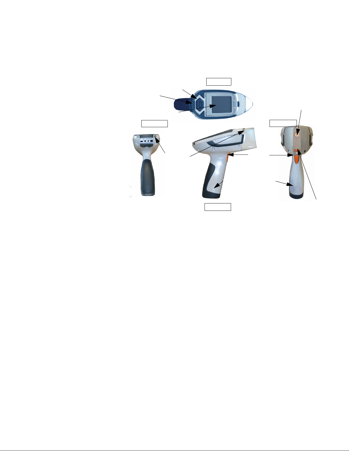
The NITON XRF
Top View
Rear View
Front View
Control panel
LED lights
Trigger
LCD touch screen
Measurement
Window
Proximity Sensor
Rear
Interlock
Battery Pack/Han-
dle
Side View
Analyzer Overview
The NITON XL3 Analyzer is a single unit, hand held, high performance
portable x-ray fluorescence (XRF) elemental analyzer.
The Control Panel
Figure 0-1. Analyzer Overview
The control panel is located on the analyzer’s top housing, directly below the
LCD touch screen (see Figure 0-1). The control panel consists of a 4 way
touch pad, a center button, and two control buttons, one on each side.
Using either the control panel or the touch screen you may navigate through
all of the analyzer’s screens and menus. You can control the movement of the
screen cursor by pressing the four way control pad in one of four directions
to highlight each of the menu options. The Select button in the center of
the four way touch pad is used to select highlighted menu options. The
on/off/escape button both controls the power to the analyzer and serves as
an "escape" button. When the on/off/escape button is pushed and
immediately released, it functions as an "escape", and brings you back to the
Main Menu from the current screen in the menu system.
ii NITON XL3 Analyzer User’s Guide Thermo Scientific
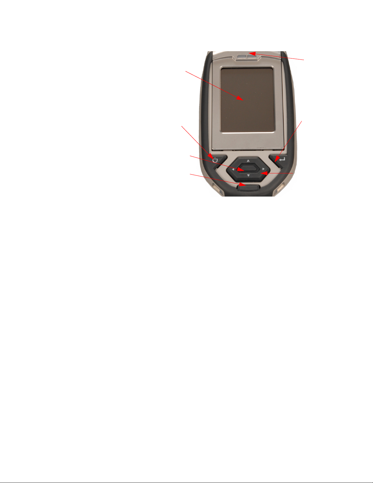
Figure 0-2. The Control Panel
LCD touch
screen
On/off/escape
button
Clear/enter
button
4-way touch pad
Interlock button
Select button
LCD touch
screen catch
Push and hold the on/off/escape button for at least 3 seconds to turn the
analyzer on.Push the on/off/escape button and hold it down for about 10
seconds to shut off power to the analyzer from any screen in the menu
system.
You also have the option of operating the analyzer, including navigating the
menu system, by using the built in touch screen. To select a menu option,
tap on the icon once. The touch screen icons have the same functionality as
the four way touch pad, the on/off/escape button, and the select or enter
button. This User's Guide will refer to the process of choosing a course of
action by selecting an icon from a menu, either using the touch screen or
using the control panel buttons, as “selecting.”
Thermo Scientific NITON XL3 Analyzer User’s Guide iii
Selecting the Return icon works everywhere throughout the User Interface
to bring you back to the previous menu from the current menu in the menu
system. Use the on/off/escape button to return to the Main Menu.

The LCD Touch Screen
The LCD Touch
Screen
The LCD Touch Screen on your XL3 Analyzer is designed to swing up and
down to different angles for ease in viewing and interacting with your
analyzer. The LCD Touch Screen is connected to your analyzer along the
base of the screen, right above the Control panel. The screen is not designed
to separate from the analyzer, but can be adjusted to any arbitrary angle
between zero degrees - that is, flush with the analyzer - and 85 degrees,
which is almost perpendicular. The LCD Touch Screen will stay at any
given angle between these extremes until moved to a different angle. When
in closed position, the screen is secured by a catch at the top center of the
screen housing.
Figure 0-3. XL3 Analyzer Showing LCD Screen Tilted.
• To raise the LCD Touch Screen, disengage the catch at the top-center of
the LCD Touch Screen housing and gently pull the screen towards you
until it is at the best angle for your use.
• To close the LCD Touch Screen, gently push away from you along the
top edge of the screen housing. The screen will swing down until the
catch solidly engages with an audible click.
Note The LCD Touch Screen cannot be removed from your XL3 analyzer.
Removing or attempting to remove the LCD Touch Screen will damage
your analyzer and void your warranty.
Note Always close your LCD Touch Screen before storing or transporting
your XL3 analyzer.
iv NITON XL3 Analyzer User’s Guide Thermo Scientific
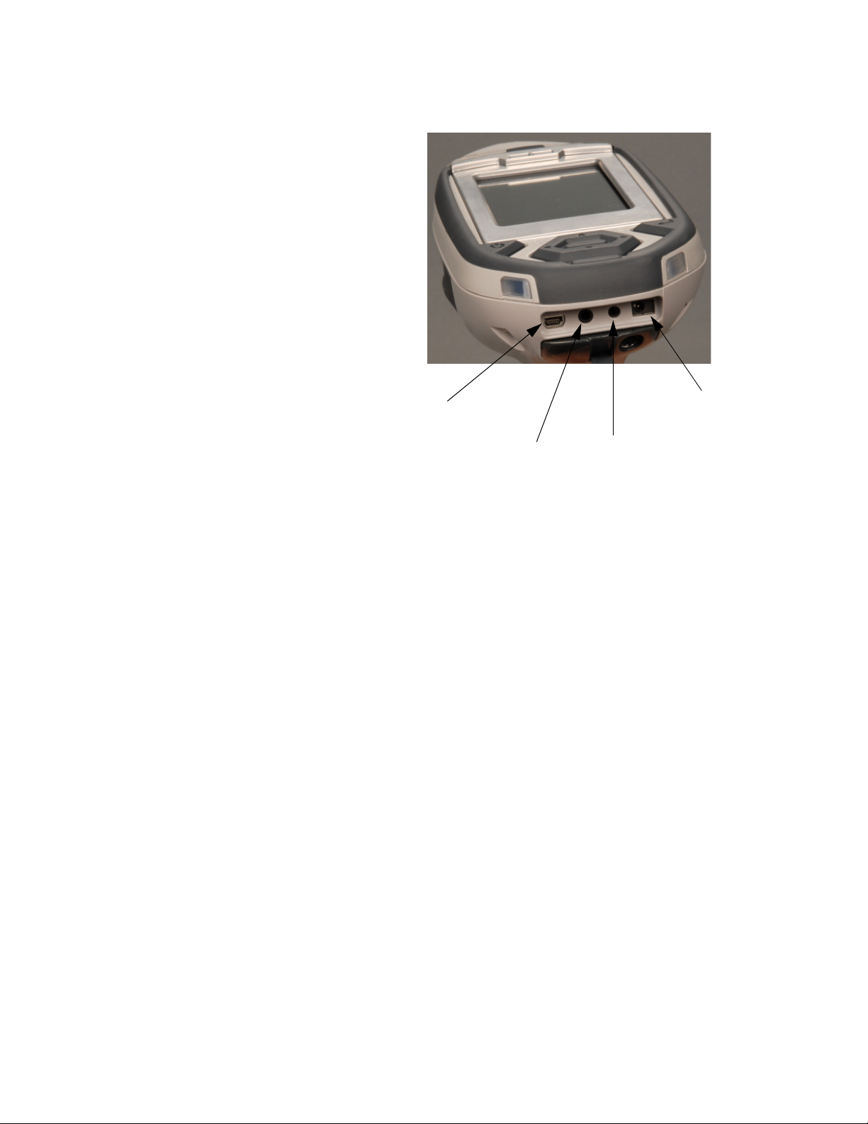
The Data Ports
Power Port
Serial Port
Remote Trigger Port
USB Port
The Data Ports
Figure 0-4. Data Ports on the XL3
USB Port The USB Port is a communications and control port, for uploading and
downloading data, configuration files, and software to the analyzer.
Remote Trigger Port The Remote Trigger Port controls the analyzer’s trigger function, for use
with the Extend-a-pole, In Situ Tripod, and test stands.
Serial Port The Serial Port is a communications and control port, for uploading and
downloading data, configuration files, and software to the analyzer.
Power Port The power port is used to run the XL3 under external power.
Thermo Scientific NITON XL3 Analyzer User’s Guide v
The Data Ports
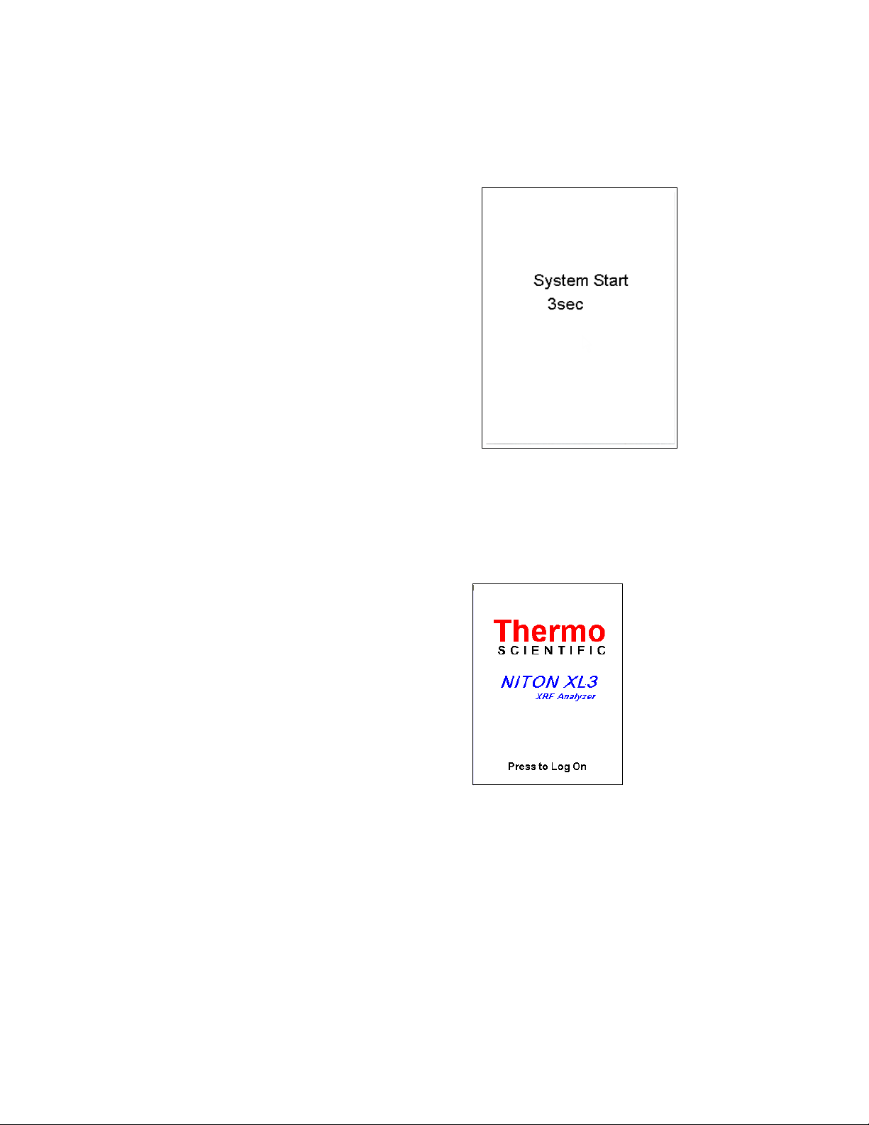
Instrument Startup
To turn on the analyzer, depress the on/off/escape button on the control
panel for approximately 10 seconds.
Figure 0-5. System Start Screen
On startup, the screen will be replaced by a Start Screen (see Figure 0-5)
which will automatically count down from 9 to 0 in increments of one
second.
Figure 0-6. Logon Screen
When the Start is complete, the Start Screen will be replaced by the Logon
screen (see Figure 0-6.) Tap anywhere on this screen to continue.
The Logon Screen will be replaced by a Warning Screen, see Figure 0-7,
advising you that this analyzer produces radiation when the lights are
flashing. You must acknowledge this warning by selecting the “Yes” button
before logging on. Selecting the “No” button will return you to the Logon
Screen.
vi NITON XL3 Analyzer User’s Guide Thermo Scientific

The Data Ports
Figure 0-7. Warning Screen
After selecting the “Yes” button, the Virtual Numeric Keypad becomes
available for you to log onto the analyzer.
Figure 0-8. Virtual Numeric Keypad for Logon
Thermo Scientific NITON XL3 Analyzer User’s Guide vii
The Data Ports
Select your 4 digit security code, followed by the enter (E) key. The
temporary password assigned by default is 1-2-3-4, followed by the “E” key.
If you enter an incorrect number, you can use the “<“ key to backspace over
it, ot use the “C” key to clear everything. After you have completed the log
on procedure, the word "USER" will appear on the bottom of the screen,
then the Main Menu will appear. Note that security codes are editable.
Please see the NDT manual for instructions on creating user-definable
passwords.
Check the date/time. The time should be set correctly for accurate and
verifiable record keeping (See Chapter 1 page 72).
Your analyzer can be stored and operated safely in temperatures from -5º C
(23º F) to 50º C (122º F). You will not be able to take a measurement if the
analyzer overheats. If it is hot to the touch, you should allow it to cool
before testing.
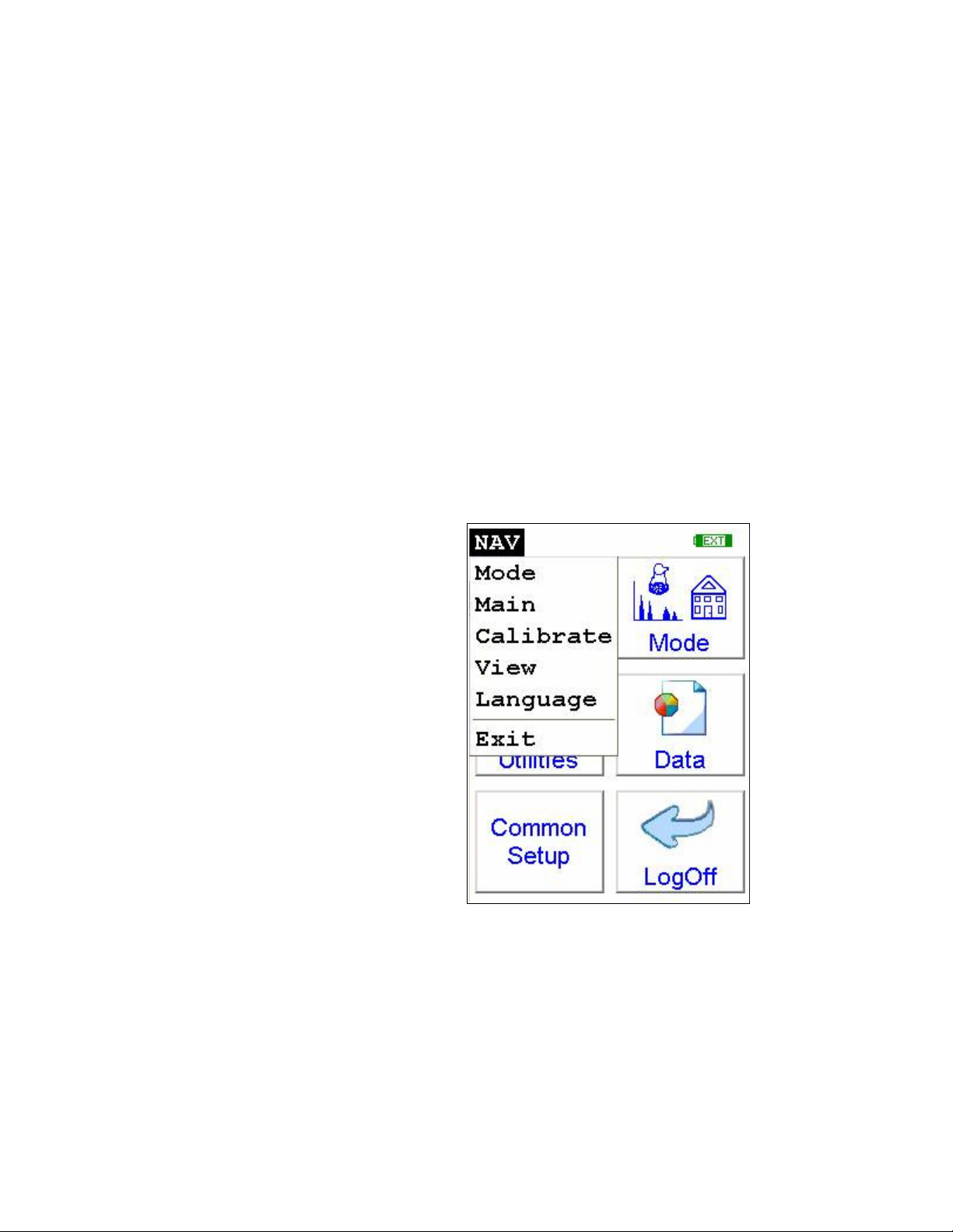
The NAV Menu
Figure 0-9. The NAV Menu
The Navigation Menu, or NAV Menu, is available in all screens, though
only through the touch screen interface. Within a menu, the particular
options available from the NAV Menu may change with the context. For
example, within the View Menu, the NAV Menu changes options
depending on the mode you are currently using.
viii NITON XL3 Analyzer User’s Guide Thermo Scientific
The Data Ports
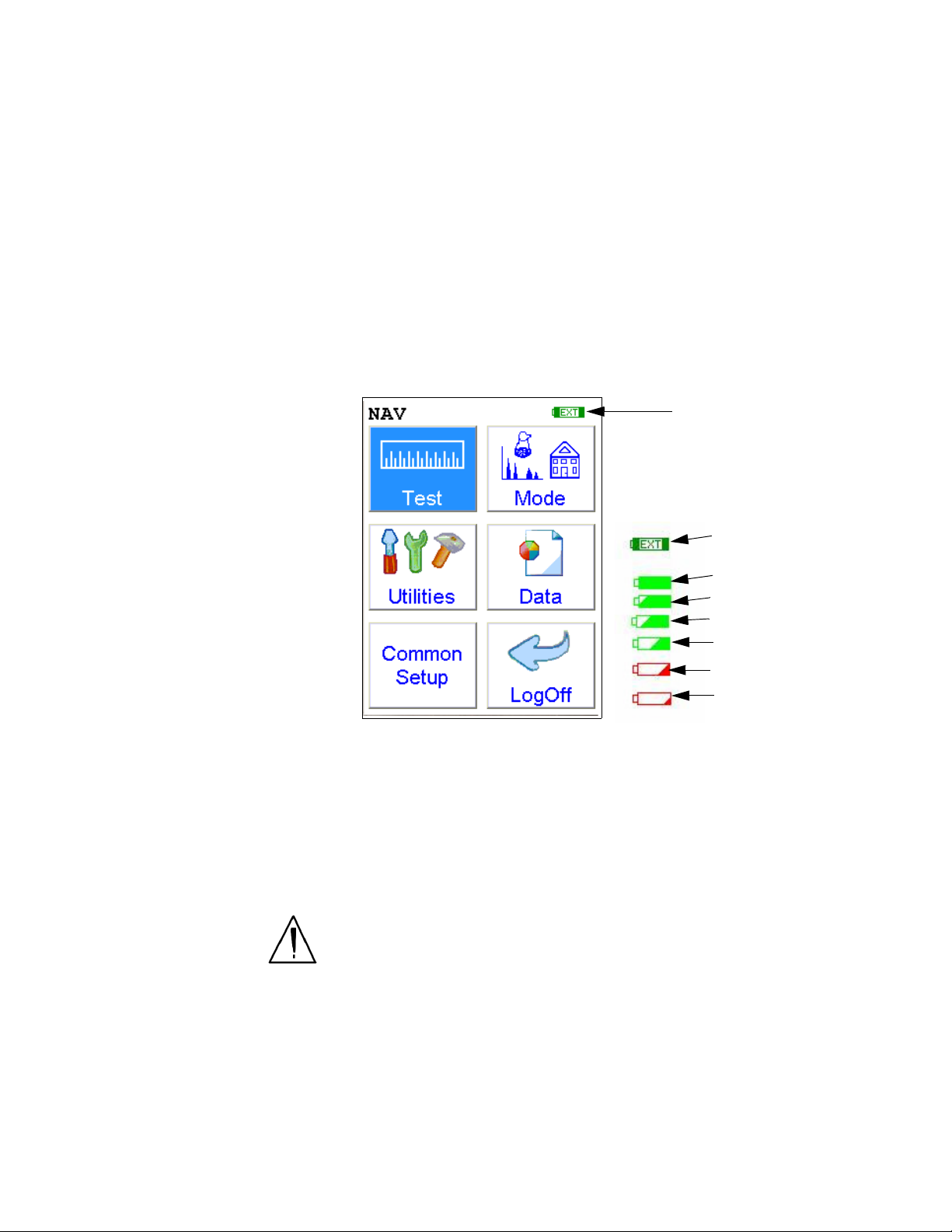
Battery Life Indicator
External Power Source
Full Battery
90% Battery Life
75% Battery Life
50% Battery Life
25% Battery Life
05% Battery Life
Battery Life Key
Access the NAV Menu by selecting the word NAV in the screen. A
drop-down menu of choices will appear. Selecting an option from the NAV
Menu will take you directly to a particular menu, no matter where you are
in the menu hierarchy. Selecting the “View” option from the NAV Menu,
for example, will bring you directly to the Data Menu.
The NAV Menu cannot be selected through the Control Panel.
The Battery Life Indicator
The Battery Life Indicator is visible on all screens in the menu system. The
indicator is visible in the top right portion of the screen, and graphically
shows you how much battery life is left, enabling you to change batteries as
needed to avoid unexpected shutdowns.
Figure 0-10. Battery Life Indicator
The more green visible in the indicator, the higher the charge. The more red
visible in the indicator, the lower the charge. It’s best to charge one battery
while using the other, to avoid work slowdowns or stoppages due to battery
charge conditions.
WARNING! In the highly unlikely event that the x-ray tube remains on
when the trigger is not depressed, disconnect the battery pack immediately
to turn off the x-ray tube, and call Thermo Fisher Scientific’s Service
Department in the United States, toll free, at (800) 875-1578, or outside
the United States at +1-978-670-7460, or your local Authorized NITON
Analyzers Service Center.
Thermo Scientific NITON XL3 Analyzer User’s Guide ix
The Data Ports
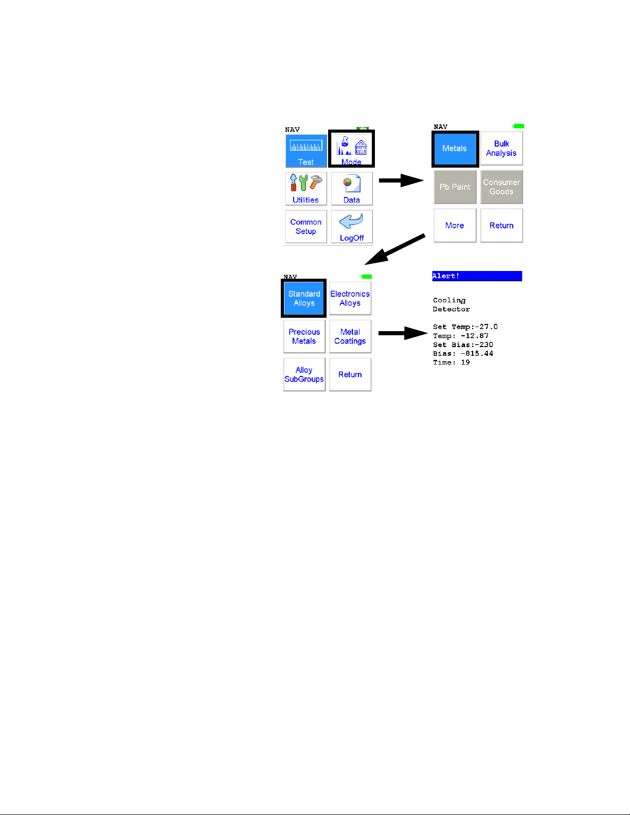
The Menu Path
The Menu Path shows you graphically how to get to the function being
described in several discrete steps from the universal start position, the Main
Menu.
Figure 0-11. Example Menu Path
In the Menu Path, the order is top to bottom, then if needed left to right,
starting with the Main Menu and ending with the function wanted. The
arrows show the succession of menus, while the icon to be selected is
highlighted by a heavy rectangular border.
This Menu path should be read as:
To get to this screen, starting at the Main Menu, select the Mode icon,
select the Metals icon, then select the Standard Alloys icon.
x NITON XL3 Analyzer User’s Guide Thermo Scientific
Applications
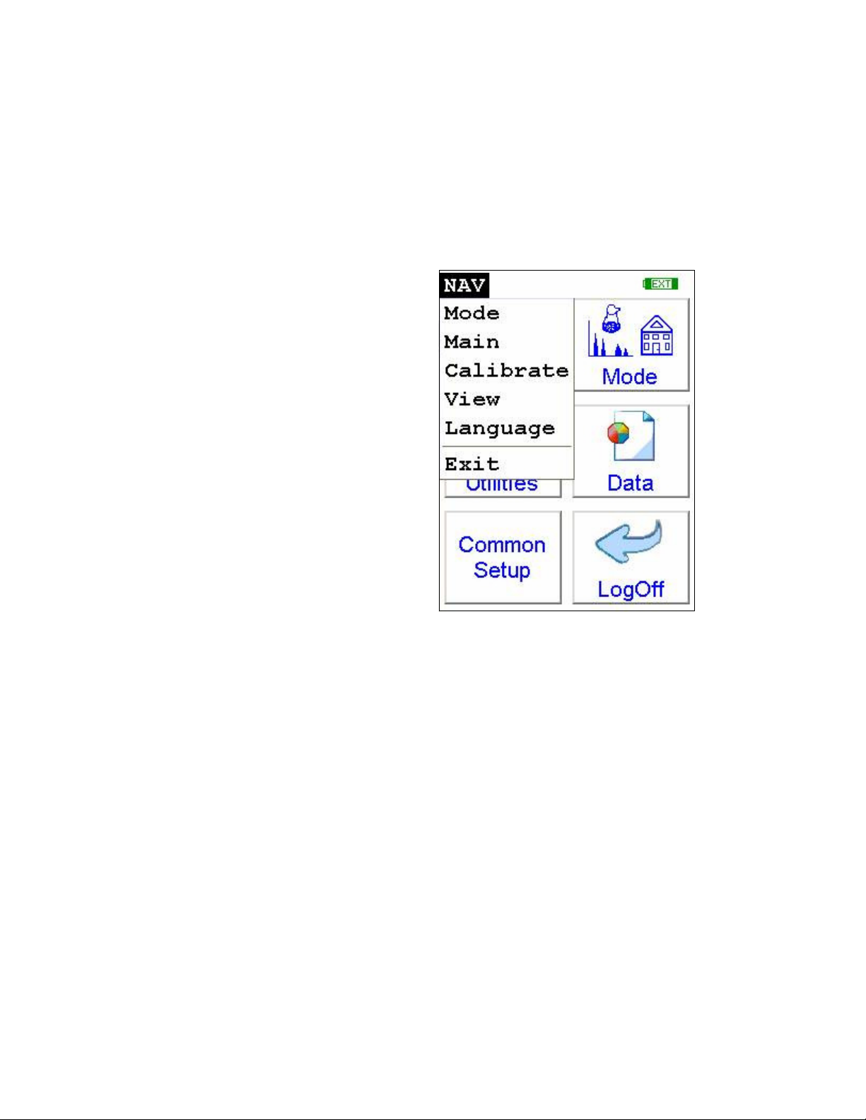
The NAV Menu
The NAV Menu
Chapter 1
The NAV Menu enables you to move between various menus and screens
directly, without going through the intervening screens. Select a destination
from the drop down menu and you will be brought directly to that menu or
screen.
Applications
Figure 1-1. The NAV Menu
Thermo Scientific NITON XL3 Analyzer User’s Guide 1-1
Applications
Tools Menu - All Enabled
Tools Menu - All Disabled
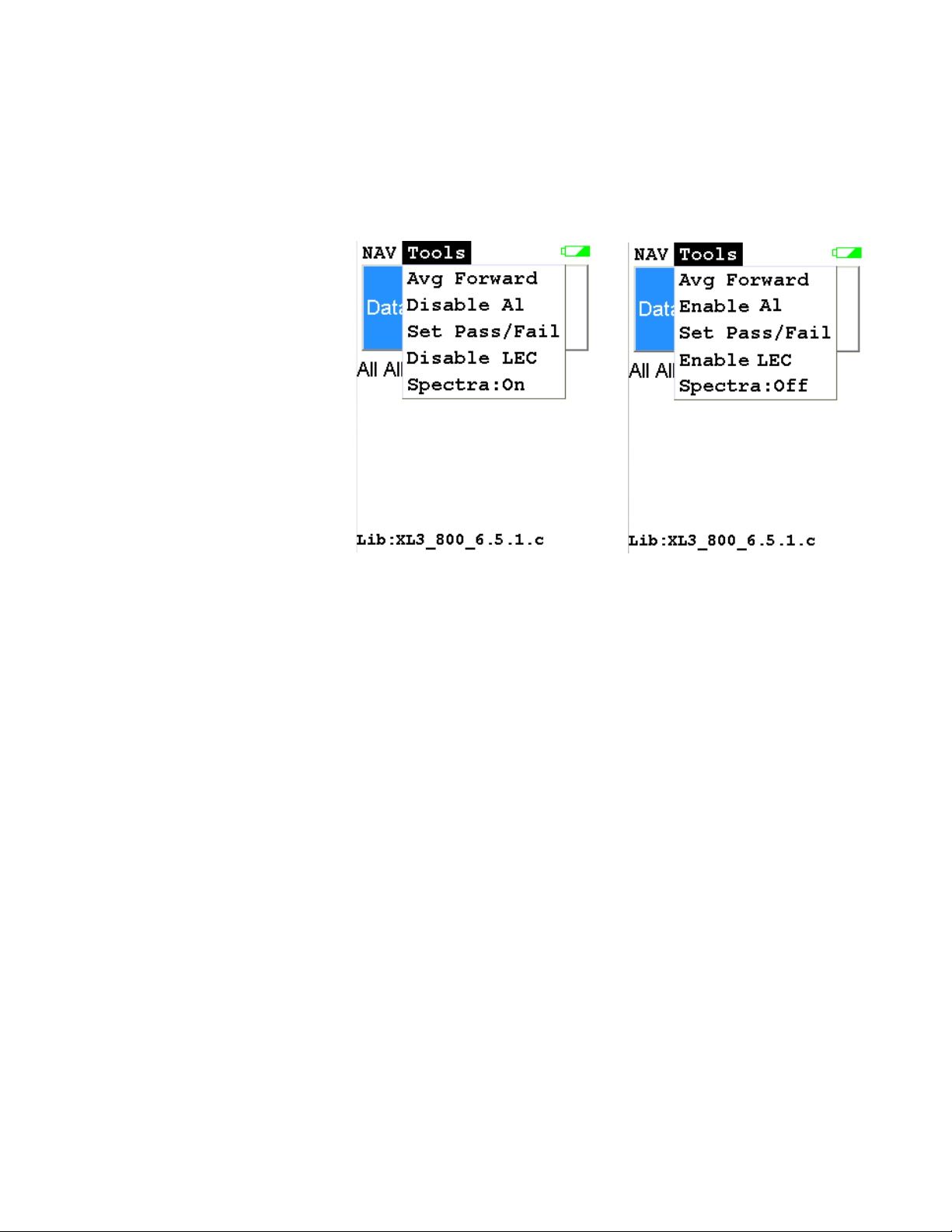
The Tools Menu
The Tools Menu
The Tools Menu enables you to perform common data-related tasks such as
printing and averaging. Select a task from the drop down menu to initiate
that task.
.
Avg Forward
Avg Back
Figure 1-2. The Tools Menu
The Tools Menu, like the NAV Menu, uses context sensitive menus. The
following is the most common menu set.
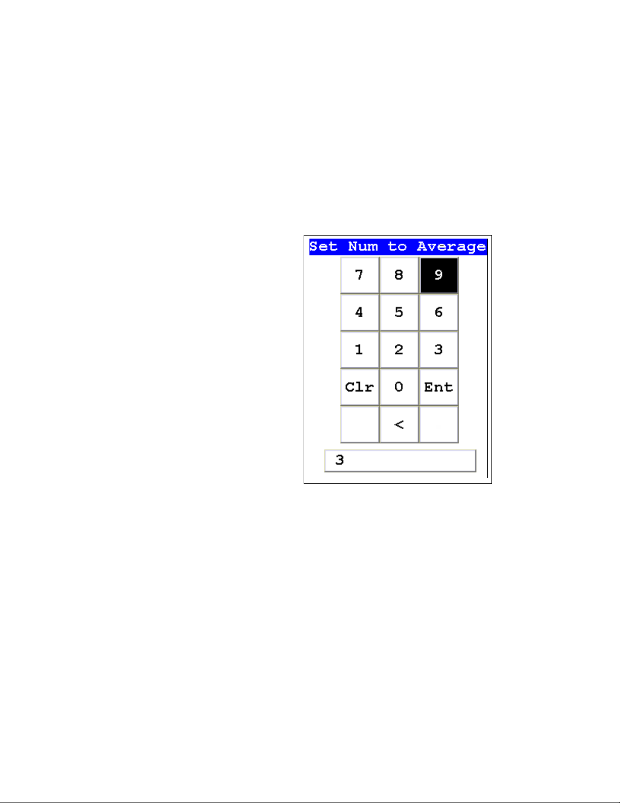
Enables you to average different readings together from this analysis
forward. Select Avg Forward to initiate future sample averaging. Avg
Forward will set up an automatic personal averaging protocol to be followed
until your analyzer is shut down, or this feature is disabled. To begin, select
the number of readings you want to average from the virtual numeric
keypad. Your analyzer will calculate an average reading after that number of
tests, and continue this pattern until stopped. For example, if you select 3
on the virtual keypad, the analyzer will automatically calculate, average, and
store a reading for every three tests you take, storing the individual readings
along the way.
Enables you to average different readings together from this analysis
backward. Select Avg Back to initiate backwards sample averaging. Avg
Back will take a number of readings you select and average their analytical
results. The range is counted from the last reading backward by the number
1-2 NITON XL3 Analyzer User’s Guide Thermo Scientific
Applications
The Tools Menu
of readings selected. If your last reading was #15, selecting 3 would average
readings #13, 14, and 15. The average is calculated, displayed, and stored
into memory as the next sequential reading number.
The range number is selected using a virtual keypad on your analyzer similar
to the keypad used for login. Select the digits in the range number from the
keypad, then select the “E” key to enter the number. “C” will clear all, and
“<“ will clear the last digit entered. The average will automatically be
displayed.
Figure 1-3. The Virtual Numeric Keypad for Averaging
Note You cannot average readings taken with different element lists - or with
different filter settings if the settings have different element lists - with either
Avg Back or Avg Forward. Alloy and Mining modes each use the same
element lists with the different filter settings, so averaging works when
switching between filter settings when in either of these modes. Thin Film
and Bulk modes both use different element lists for different filter settings,
and readings with different filter settings cannot be averaged when using
either of these modes. You can never average readings taken in different
modes.
Note The Tools Menu is only available when viewing readings, and the
menu is only accessible through the touch screen interface or NDTr.
Thermo Scientific NITON XL3 Analyzer User’s Guide 1-3
Applications
The Tools Menu
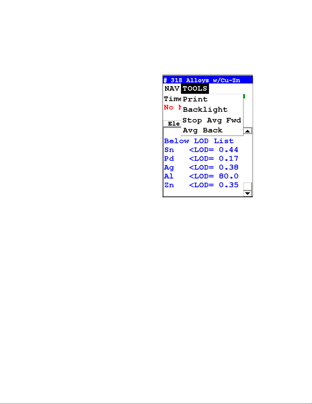
Stop Avg Fwd/Back
Avg Back and Avg Forward are toggles. The option on the Tools Menu
changes to its opposite when selected. To stop averaging, select Stop Avg
Fwd or Stop Avg Back from the Tools Menu as appropriate.
Figure 1-4. The Tools Menu - Averaging Toggles
1-4 NITON XL3 Analyzer User’s Guide Thermo Scientific
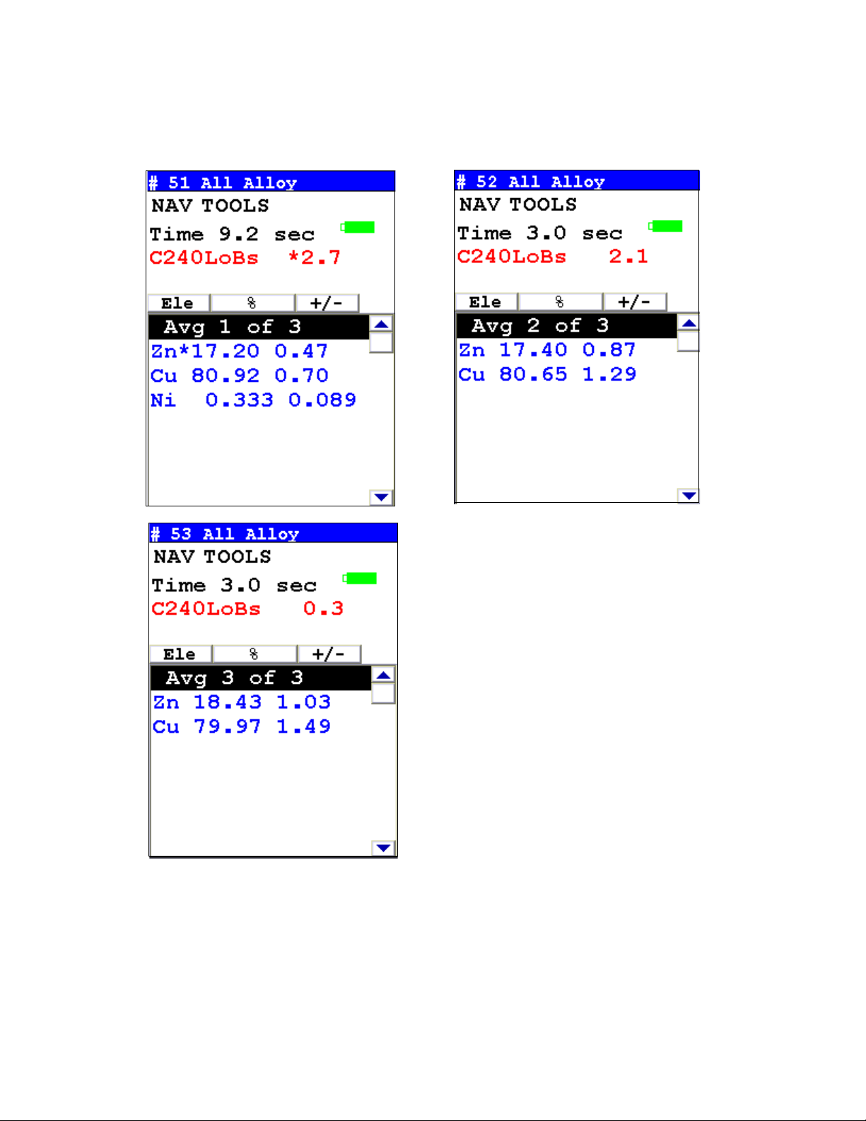
Example Averaging
Applications
Example Averaging
Figure 1-5. Averaging example: 3 readings
Thermo Scientific NITON XL3 Analyzer User’s Guide 1-5
Applications
Live Spectrum Feed
Live Spectrum Feed
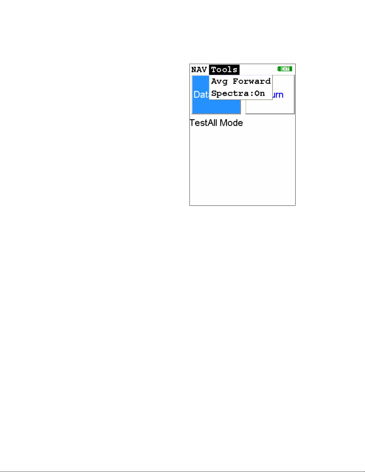
The Tools Menu may contain a toggle option to display live spectra as
sample analysis occurs.
Figure 1-6. The Tools Menu showing the Spectra On/Off Toggle
1-6 NITON XL3 Analyzer User’s Guide Thermo Scientific
Applications
Live Spectrum Feed
Activating and
Deactivating the Live
Spectrum
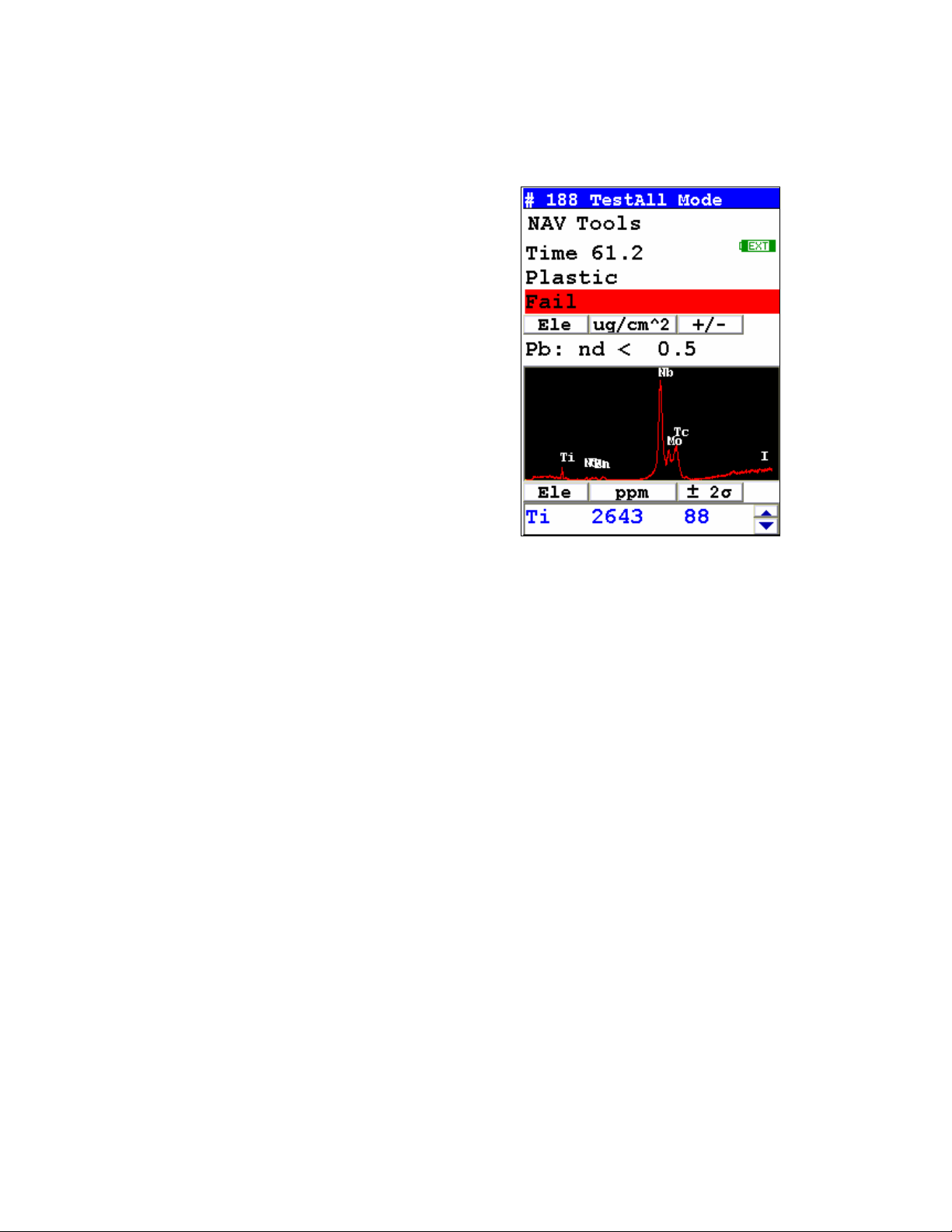
From the Tools Menu, select Spectra : On to turn the Spectrun feed on.
Once the spectrum is displayed, selecting Spectra : Off from the Tools Menu
will stop the live spectrum display.
Figure 1-7. Test Screen Showing Live Spectrum
Thermo Scientific NITON XL3 Analyzer User’s Guide 1-7

Applications
Live Spectrum Feed
1-8 NITON XL3 Analyzer User’s Guide Thermo Scientific

Analyzing Bulk
Samples
Analyzing Bulk Samples
CAUTION Whenever you turn on your NITON Analyzer after it has been
off for more than 30 minutes, you should measure your check sample to
assure proper operation. If the instrument is not reading properly, you
should re-calibrate your NITON Analyzer's sample analysis electronics
before you start to take readings. When the instrument is turned on after
being off for more than 30 minutes, your NITON analyzer will require a 10
minute warm-up period before the instrument can be calibrated, unless this
10 minute warm-up period is manually overridden.
There are six different methods of operation for taking a sample
measurement, and your analyzer will be configured to use one of those
methods for soil samples, depending on the regulatory requirements of your
locality. These methods are:
• Trigger-Only method. With the Trigger-Only method, you only
need to place the measurement window close to the sample to be
analyzed and pull the trigger for sample analysis to be initiated.
• Trigger-and-Proximity-Sensor method. With the
Trigger-and-Proximity-Sensor method, you must place the
measurement window against the sample to be analyzed to engage
the proximity sensor on the front of the instrument, then pull the
trigger for sample analysis to be initiated.
• Momentary-Trigger-Touch-and-Proximity-Sensor method. With
the Momentary-Trigger-Touch-and-Proximity-Sensor method, you
must place the measurement window against the surface to be
analyzed to engage the proximity sensor on the front of the
instrument, then pull the trigger. The trigger may be released and
the reading will continue until you release the proximity button, or
other criteria (such as Max Time) are reached.
• Trigger-and-Interlock method. With the Trigger-and-Interlock
method, you need to place the measurement window close to the
sample to be analyzed, press and keep pressing the interlock button
at the rear of the instrument with your free hand, then pull the
trigger for sample analysis to be initiated.
Thermo Scientific NITON XL3 Analyzer User’s Guide 1-9

Analyzing Bulk Samples
• Trigger-Interlock-and-Proximity-Sensor method. With the
Trigger-Interlock-and-Proximity-Sensor method, you must place the
measurement window against the sample to be analyzed to engage
the proximity sensor on the front of the instrument, press and keep
pressing the interlock button at the rear of the instrument with your
free hand, then pull the trigger for sample analysis to be initiated.
• Easy Trigger method. With the Easy trigger method, you need only
place the measurement window against the sample area and pull the
trigger once to initiate a sample analysis. Your analyzer will
continuously sample the backscatter, using a complex internal
algorithm, to determine if the measurement window is against a
sample or pointing to the empty air. If it finds that there is no
sample directly against the measurement window, the analyzer will
stop directing radiation through the window as soon as this
determination is made.
Note The analyzer is constantly checking the backscatter characteristics to
determine if a sample is against the measurement window, whether or not
the Easy Trigger method is being used, and will shut off any radiation
directed through the window if it determines that there is no sample
present.
With any of these methods, analysis will stop if any one of the preconditions
are violated. For example, with the Trigger-Interlock-and-Proximity-Sensor
method, if the trigger or the Proximity Sensor or the Interlock is released,
the reading will stop immediately, and the X-ray tube will shut down.
After your NITON analyzer is calibrated, initiate a sample reading using the
appropriate method. If you attempt to initiate a sample reading using a
different method, the analyzer will inform you that one or more of the
preconditions need to be met in order for sample analysis to begin. Initiate
the proper preconditions for operation to turn on the x-ray tube, and begin
a measurement. Although the four LED lights will begin to flash as soon the
initiating preconditions are met, as a safety precaution, the x-ray tube will
not turn on immediately, and no reading will begin for approximately 0.5
seconds.
Note The four LED lights will blink during calibration.
1-10 NITON XL3 Analyzer User’s Guide Thermo Scientific
Analyzing Bulk Samples
WARNING! The preconditions for operation must be continued for the
duration of the reading. If the preconditions are violated, the x-ray tube will
turn off, the calibration shutter will close, and the measurement will end.
The four LED lights will stop blinking when the measurement is ended.
The flashing of the LED lights is not synchronized to minimize power
consumption.
To end the test, simply release the trigger mechanism, or any other
applicable preconditions.
WARNING! When all four LED lights are blinking, the x-ray tube is on.
This should only occur during a measurement, while the preconditions for
operation are met. On startup, the front pair of lights will blink. If the LED
lights blink at any other time, disconnect the battery pack and call Thermo
Scientific’s Service Department in the United States, toll free, at (800)
875-1578, or outside the United States, at +1-978-670-7460, or your local
Authorized NITON Analyzer Service Center.
Your NITON Analyzer will display the Results Screen throughout the
duration of each reading, The Results Screen is updated regularly
throughout the reading. When the reading is complete, a final screen update
will appear, and your NITON analyzer will display the final results of the
measurement which has just been completed.
WARNING! Do not attempt to take measurements while downloading
readings! This will generate an error requiring a system reset, and may
corrupt your stored readings, requiring all stored readings to be erased.
Thermo Scientific NITON XL3 Analyzer User’s Guide 1-11
The Data Entry Screen
Virtual Keyboard
Button
Parameter Field
Name
Drop-down List
Button
Parameter Field
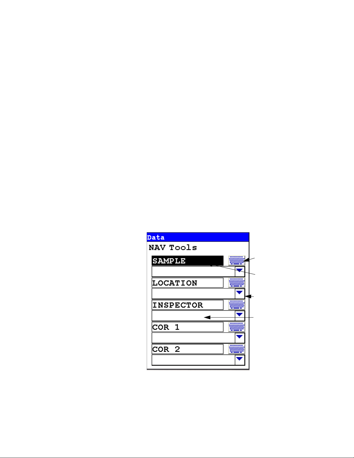
The Data Entry Screen
The Data Entry Screen is accessed whenever you select the Data Entry
icon from any screen. This screen allows you to input data in several
different fields, or categories, concerning your sample, in several different
ways:
• By selecting the Virtual Keyboard button and typing the parameter in
using the Virtual Keyboard.
• By creating a new, or editing your analyzer's existing, '.ndf' file through
the NDT program. You can then select from the various custom options
you have created using the Drop-down List button.
These fields are saved along with the subsequent reading, and allow you to
associate important information about the sample directly with the reading,
so that you have a full description of the sample tied into the reading itself.
Once you have input data into a field, that information carries over into the
next reading, so that you only have to input the information that has
changed since the last reading. For example, if you are analyzing several
samples of a particular lot, you only need to input the lot information once
during that series of readings, changing only the sample name.
Figure 1-1. The Data Entry Screen - First page
1-12 NITON XL3 Analyzer User’s Guide Thermo Scientific
The Data Entry Screen
This is the first section of the Data Entry Screen. There are five
parameters in this section.
Selecting Sample allows you to input the sample name parameter.
Selecting Location allows you to input the particular Location information,
if known.
Selecting Inspector allows you to input the parameter for the Inspector’s
name.
Selecting Cor1 allows you to input information on the sample’s origin
Latitude Coordinate.
Selecting Cor2 allows you to input information on the sample’s origin
Longitude Coordinate.
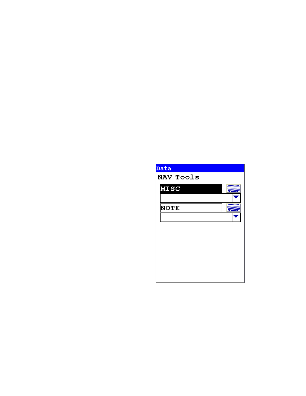
This is the second section of the Data Entry Screen. There are two
parameters in this section.
Selecting Misc allows you to input the any miscellaneous parameters.
Selecting Note allows you to input any Note information, if wanted.
Thermo Scientific NITON XL3 Analyzer User’s Guide 1-13
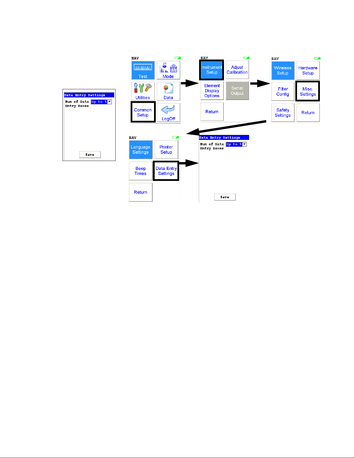
Changing the Data Entry Screen to Two Column
Changing the Data
Entry Screen to Two
Column
Figure 1-2. Data Entry Settings Menu Path
You can change the Data Entry display from the default single column to
two columns in order to fit all the fields on one page, if you prefer. Select the
Data Entry Settings icon from the Misc. Settings Menu to change your
preferences.
1-14 NITON XL3 Analyzer User’s Guide Thermo Scientific
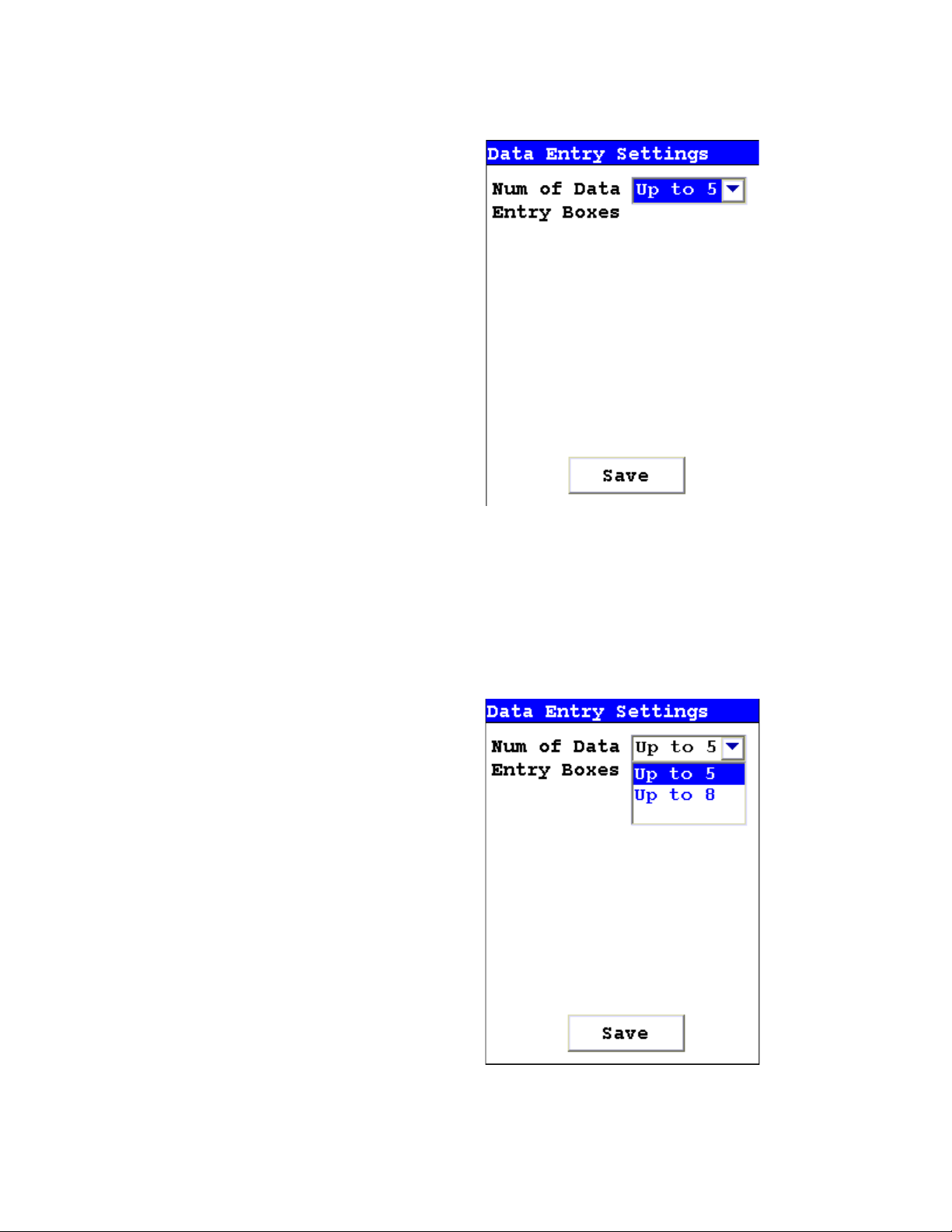
Changing the Data Entry Screen to Two Column
Figure 1-3. Data Entry Settings Screen
Selecting the triangle button to the side of the Num of Data Entry Boxes
field will open a drop down menu. From this menu you can choose between
showing up to five boxes per page, the default, and up to eight boxes per
page. Select the option you prefer, and select the Save button to save the
setting.
Figure 1-4. The Drop Down Menu
Thermo Scientific NITON XL3 Analyzer User’s Guide 1-15
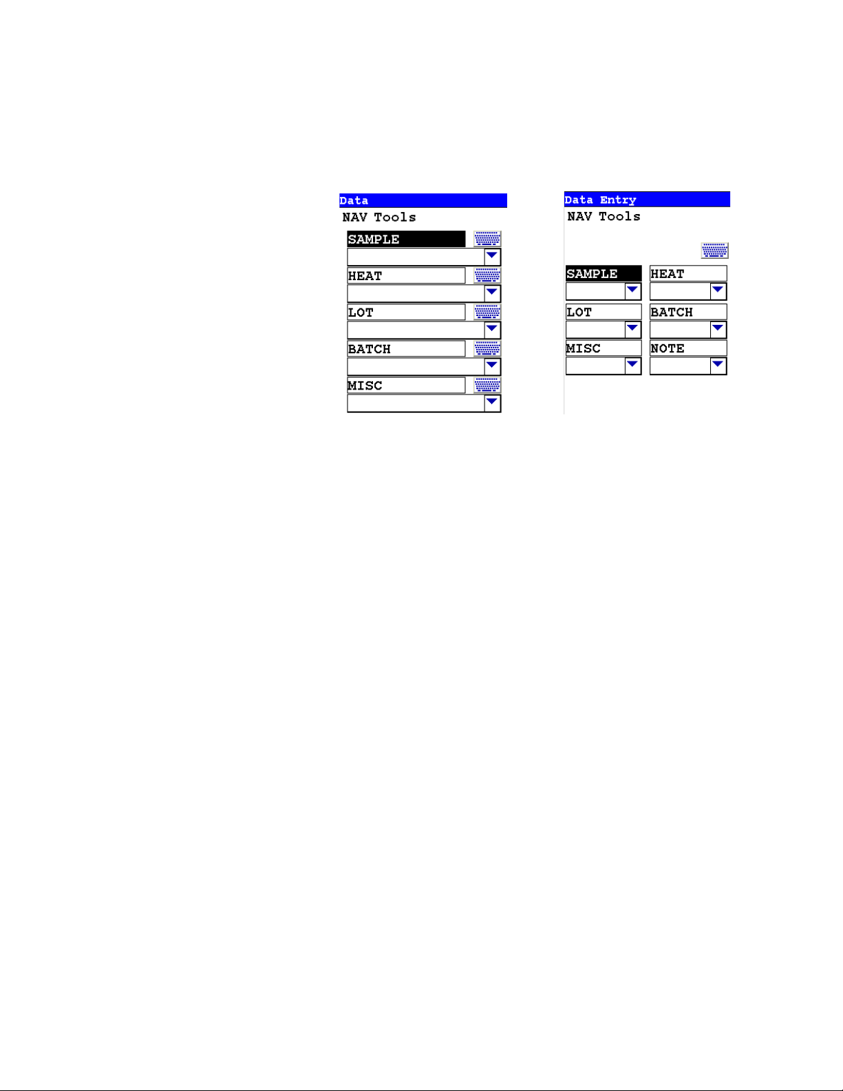
Changing the Data Entry Screen to Two Column
Up to Five Boxes
Up To Eight Boxes
Under the default setting, a mode with more than five boxes will open up a
second page to display the remaining boxes. Under the optional setting, a
mode with up to eight boxes will display on one page, with the overflow
page not opening unless there are nine or more Data Entry boxes.
Figure 1-5. Comparing the Data Entry Display Options
With the default, up to five boxes, setting, the boxes are longer, and can
display more descriptive test. With the optional, up to eight, setting, the
boxes are shorter, but retain the full descriptive text internally. Choose
whichever settign you feel most comfoortable working with.
1-16 NITON XL3 Analyzer User’s Guide Thermo Scientific
 Loading...