

Page 1

NESLAB DIMAX
DI Maximum Cooler
Thermo Manual P/N U00858 Rev. 12/28/05
Installation-Operation-
Basic Service
Visit our Web site at:
http://www.thermo.com/tc
Product Service Information, Applications
Notes, MSDS Forms, e-mail.
Voice Info: (800) 258-0830
Page 2

Thermo Fisher Scientific
Sales, Service, and Customer Support
25 Nimble Hill Road
Newington, NH 03801
Tel : (800) 258-0830 or
(603) 436-9444
Fax : (603) 436-8411
www.thermofisher.com/tc
25 Nimble Hill Road
Newington, NH 03801
Tel: (800) 258-0830
Sales: 8:00 am to 5:00 pm
Service and Support: 8:00 am to 6:00 pm
Monday through Friday (Eastern Time)
Fax: (603) 436-8411
service.tc.us@thermofisher.com
Dieselstrasse 4
D-76227 Karlsruhe, Germany
Tel : +49 (0) 721 4094 444
Fax : +49 (0) 721 4094 300
info.tc.de@thermofisher.com
Building 6, No. 27
Xin Jinqiao Rd., Shanghai 201206
Tel : +86(21) 68654588
Fax : +86(21) 64457830
info.china@thermofisher.com
Statement of Copyright
Copyright © 2007 Thermo Fisher Scientific. All rights reserved.
This manual is copyrighted by Thermo Fisher Scientific.
Users are forbidden to reproduce, republish, redistribute, or resell any materials from this
manual in either machine-readable form or any other form.
Page 3

DIMAX DI MAXIMUM COOLER
PREFACE
SECTION I
Safety
SECTION II
General Information
SECTION III
Installation
SECTION IV
Operation
Compliance ............................................................................................ 3
Unpacking .............................................................................................. 3
After-sale Support ................................................................................... 3
Warnings ................................................................................................ 4
Description ............................................................................................. 5
Specifications ......................................................................................... 6
Site ......................................................................................................... 7
Facility Water Requirements................................................................... 7
Electrical Requirements .......................................................................... 7
Field Wiring Requirements ...................................................................... 7
Plumbing Requirements .......................................................................... 9
Fluids ..................................................................................................... 10
Filling Requirements ............................................................................... 10
Microprocessor Controller ....................................................................... 11
LEDs ...................................................................................................... 11
Fault Messages ...................................................................................... 16
SECTION V
Maintenance
Start Up .................................................................................................. 17
Flow Transducers ................................................................................... 18
Low Fluid Level Safety ............................................................................ 18
Autorefill ................................................................................................. 18
Emergency Off (EMO) ............................................................................ 18
Remote Interface .................................................................................... 19
Resistivity Sensor ................................................................................... 20
DeviceNet ............................................................................................... 20
DeviceNet Interface ................................................................................. 21
DeviceNet Messaging ............................................................................. 22
MODULE STATUS LED .......................................................................... 23
NETWORK STATUS LED ....................................................................... 23
Service Contracts ................................................................................... 25
Deionizing Cartridge ................................................................................ 25
Cleaning ................................................................................................. 25
- 1 -
Page 4

SECTION VI
Service & Troubleshooting
Algae ...................................................................................................... 26
Checklist ................................................................................................ 26
Service Assistance ................................................................................. 27
SECTION VII
Diagrams
Flow Diagram .......................................................................................... 28
Wiring Diagrams ..................................................................................... 29
- 2 -
Page 5

Compliance
Unpacking
Preface
Listed to:
UL 61010-1 2nd Edition
CSA C22.2 #61010.1 2nd Edition
Products tested and found to be in compliance with the requirements defined in
the EMC standards defined by 89/336/EEC as well as Low Voltage Directive
(LVD) 73/23/EEC can be identified by the CE Mark on the rear of the unit. The
testing has demonstrated compliance with the following directives:
LVD, 73/23/EEC Complies with IEC/EN61010-1
EMC, 89/336/EEC IEC/EN61326-1
For any additional information, refer to the Declaration of Conformity that
shipped with the unit.
Retain all cartons and packing material until the unit is operated and found to
be in good condition. If the unit shows external or internal damage, or does
not operate properly, contact the transportation company and file a damage
claim. Under ICC regulations, this is your responsibility.
After-sale Support
Thermo Electron Corporation is committed to customer service both during and
after the sale. If you have questions concerning the operation of your unit,
contact our Sales Department. If your unit fails to operate properly, or if you
have questions concerning spare parts or Service Contracts, contact our
Customer Service Department. Before calling, please obtain the following
information from the unit's serial number label:
- BOM number _________________________
- Serial number _________________________
- Software version (see page 14)____________
- 3 -
Page 6

Warnings
Section I Safety
Make sure you read and understand all instructions and safety precautions
listed in this manual before installing or operating your unit. If you have any
questions concerning the operation of your unit or the information in this
manual, contact our Sales Department (see After-sale Support).
Observe all warning labels.
Never remove warning labels.
Never operate damaged or leaking equipment.
Never operate the unit without cooling fluid in the reservoir.
Always turn off the unit and disconnect the line cord from the power
source before performing any service or maintenance procedures.
Always empty the reservoir before moving the unit.
Always turn off the unit and disconnect the line cord from the power
source before moving the unit.
Additional safety warnings are posted throughout the manual. These warnings are designated by an exclamation mark inside an equilateral triangle with
text highlighted in bold. Read and follow these important instructions. Failure
to observe these instructions can result in permanent damage to the unit,
significant property damage, or personal injury or death.
- 4 -
Page 7
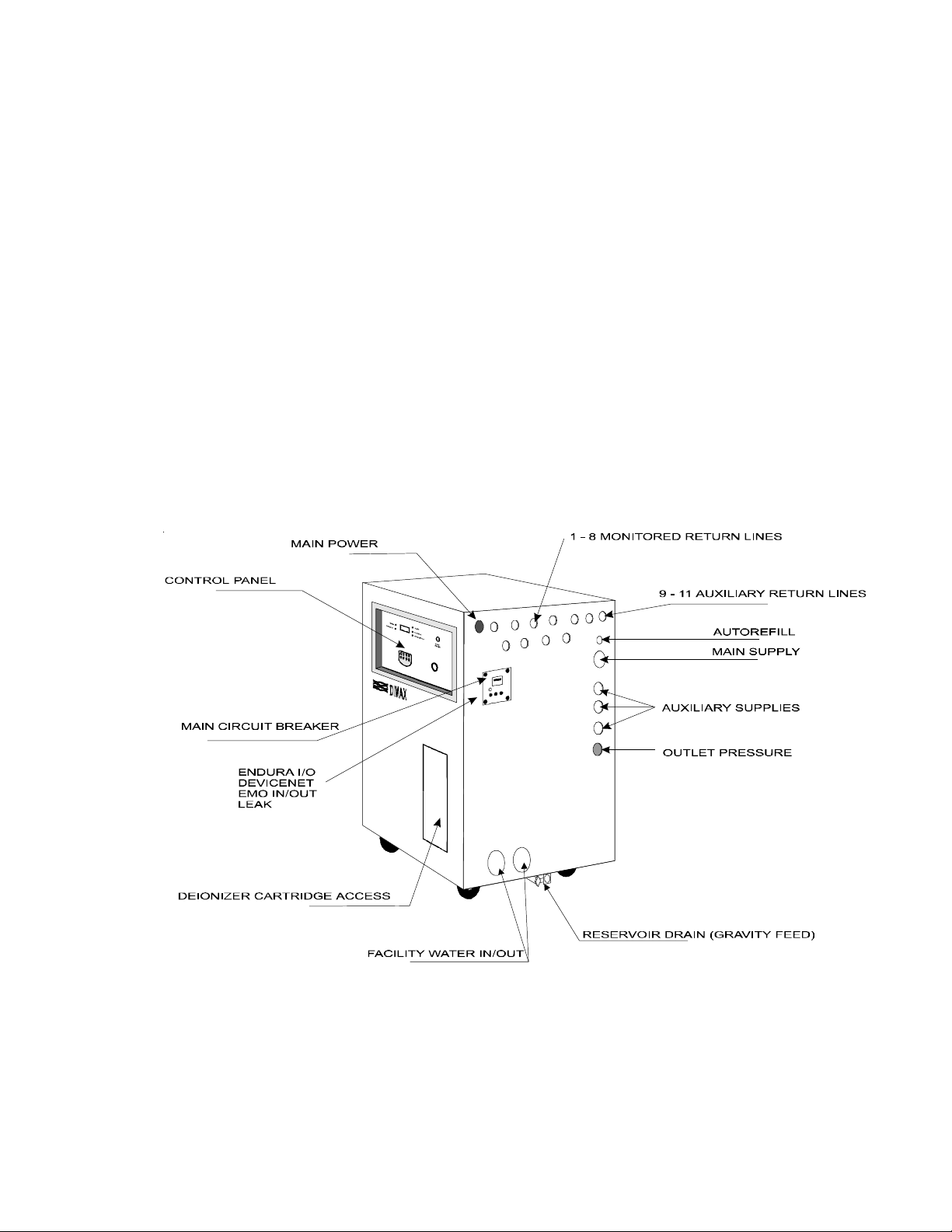
Description
Section II General Information
The DIMAX Liquid to Liquid Heat Exchanger is designed to remove heat
loads from liquid-cooled instruments. The unit uses facility cooling or tap
water as the secondary cooling medium to remove heat from the primaryfluid
in the closed recirculation loop.
The unit consists of a plate heat exchanger, recirculation pump, stainless
steel reservoir, built-in replaceable deionizing cartridge, and a microprocessor
controller. The controller monitors temperature, controls resistivity and
displays all fluid flows.
The unit has 11 return lines. The flow rate in 8 of these lines as well as the
facility flow line is monitored by flow transducers. The unit also has fluid level
sensors designed to protect the unit's pump and your application. A resistivity
sensor monitors resistivity and sends a signal to the controller when replacement is necessary.
- 5 -
Page 8
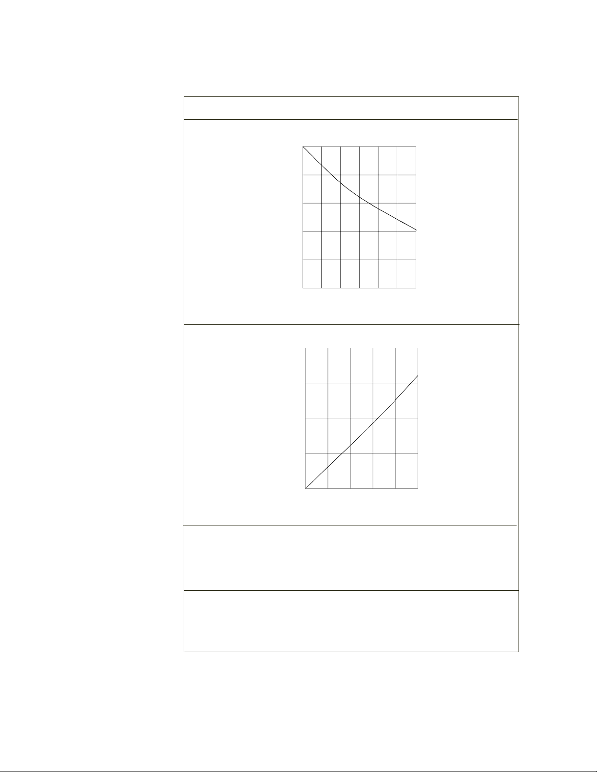
Specifications
Temperature Range
Pumping Capacity
Facility Water
Requirements
1
25
20
15
10
Pressure PSI
5
20
15
+20°C to +30°C
10 20 30 40 50 60
Flow rate (gallons per minute)
Reservoir Volume
Gallons
Liters
Unit Dimensions
(H x W x D)
Inches
Centimeters
10
Pressure PSI
5
10 20 30 40 50
Flow rate (gallons per minute)
68.0
257
55 x 32½ x 32½
139.7 x 82.6 x 82.6
1. Lower limit determined by facility water temperature.
- 6 -
Page 9

Site
Facility Water
Requirements
Section III Installation
The unit should be placed in a location with easy access to a facility cooling
water and a drain.
For proper ventilation, a minimum clearance of 6 inches ( 15 centimeters) at
the rear of the unit is necessary.
Never place the unit in a location where excessive heat, moisture, or
corrosive materials are present.
For the unit to operate at its full rated capacity, the facility water flow rate must
be at least 50 gallons per minute and the facility water temperature must be
between 17°C to 22°C. If the facility water does not meet these requirements,
the cooling capacity will be reduced.
Facility water supply should not exceed 100 psi and the maximum pressure
differential between facility water supply and return should not exceed 65 psi.
Electrical
Requirements
Field Wiring
Configuration
Refer to the serial number label on the rear of the unit for the specific
electrical requirements of your unit.
For high-voltage 380-415/480V units only, ensure the voltage selector
switch is in the correct position to meet the power source rating. The
switch is located behind the main circuit breaker panel on the righthand side of the unit.
Ensure the voltage of the power source meets the specified voltage, ±10%.
Make sure an adequate ground connection is provided.
The configuration is a 3 phase, 4 wires with PE. Remove the circuit breaker
panel cover to access the DIMAX main circuit breaker (CB1). The Circuit
Breaker is rated for Ring Lugs (RL).
The copper wires of the multi-conductor flexible power cable are terminated
with ring lugs with #10 holes at both ends. Crimp the ring lugs.
One terminal is connected to the branch circuit breaker, and the other to CB1.
- 7 -
Page 10

at the mainframe
consult Thermo NESLAB
consult Thermo NESLAB
Table 1 Facilities Requirements
Facilities Type Fitting Size Fitting Type Material Pressure Flow Comments
Monitored return 1" FPT Brass ~5 psi >10gpm at <15psi
Auxiliary return 1" FPT Brass ~5 psi
Main Supply 2" FPT Brass 25 psi max 50gpm at <15psi
Auxiliary supply 1" FPT Brass 25 psi max
Facility water In/Out 2" FPT Brass 100 psi max 50gpm max Higher pressures-
- 8 -
Autorefill ½" FPT Brass 75 psi max Unregulated Higher pressures-
Reservoir Drain ½" FPT Brass Atmospheric N/A
Reservoir Overflow 1 FPT Brass Atmospheric N/A
Supplied
AC Power Input Customer N/A N/A N/A N/A
Page 11

Plumbing
Requirements
The multi-conductor cable has 3 current carrying conductors and 1 noncarrying conductor (Ground). Each cable conductor is made of stranded
copper, and is at least size AWG 12.
The multi-conductor flexible jacketed cable is type S, SO, ST and STO with
insulation rated for a minimum of 600 V, 75°C (140°F).
The multi-conductor cable enters the DIMAX through a flex-type, non-metallic,
¾ inch diameter strain relief. 3-4 inches of the insulated jacketed should
remain un-stripped for slippage purposes.
Each conductor is connected to the DIMAX main circuit breaker using the ring
lug. Torque each screw to 20 in-lbs.
The Ground conductor should be approximately 6 inches long in order to reach
the ground bus through the ring lug. Torque the screw as well to 20 in-lbs.
Before installing the unit to an instrument that previously used tap water as a
cooling fluid, flush the instrument several times to remove any rust or scale
that has built up. The manufacturer of the instrument should be able to
recommend a cleaning fluid for their equipment.
The plumbing connections are located on the right side of the unit and are
labelled FACILITY WATER OUT (2"FPT), FACILITY WATER IN (2"FPT), MAIN
SUPPLY (2"FPT), AUXILIARY SUPPLY 1 - 3 (1"FPT), RETURN LINES 1 - 8
(1"FPT), AUXILIARY RETURN LINES 9 -11 (1"FPT), AUTOREFILL (½" FPT),
and OVERFLOW (1"FPT).
Connect the SUPPLY line to the inlet of your application. Connect the eight
MONITORED RETURN LINES and the three UNMONITORED AUXILIARY
RETURN LINES to the applicable lines (monitored or unmonitored). Connect
the FACILITY WATER IN to the cooling water supply and the FACILITY
WATER OUT to the cooling water drain or return.
Flexible tubing, if used, should be of heavy wall or reinforced construction.
The FACILITY WATER IN is subjected to the maximum pressure of the
facility cooling water. Hose connections should be securely clamped and rated
to withstand the maximum pressure of the system. Facility water supply
should not exceed 100 psi. Avoid running tubing near radiators, hot water
pipes, etc. If substantial lengths of tubing are necessary, insulation
may be required to prevent loss of cooling capacity.
- 9 -
Page 12

Fluids
The units pump is capable of generating up to 40 psi. The SUPPLY plumbing
should be rated to withstand that pressure.
Tubing and insulation are available from Thermo. Contact our Sales Department
for more information (see Preface, After-sale Support).
It is important to keep the distance between the unit and the instrument being
cooled as short as possible, and to use the largest diameter tubing practical.
Tubing should be straight and without bends. If diameter reductions must be
made, they should be made at the inlet and outlet of the instrument being
cooled, not at the unit.
If substantial lengths of cooling lines are required, they should be pre-filled with
cooling fluid before connecting them to the unit.
Never use flammable or corrosive fluids with this unit.
Do not use automobile anti-freeze. Commercial anti-freeze contains
silicates that can damage the pump seals. Use of automobile antifreeze will void the manufacturers warranty.
Filling Requirements
The selected fluid must have a viscosity of 50 centistokes or less at the lowest
operating temperatures.
DEI water is the recommended fluid for operation.
NOTE: The DEI cartridge is intended for maintaining resistivity only. If tap water
is used the cartridge will not last very long and will take a long time to come up
to resistivity.
The reservoir must be filled with a minimum of 16 gallons to ensure the pump
head remains submerged.
The unit has a nominal evaporation rate of up to 2.5 gallons per day. Ensure
the autorefill system is installed.
Autorefill will activate if the level is below 20 gallons and de-activate above 22.5
gallons.
The total reservoir capacity is 68 gallons (257 liters). To prevent siphoning, all
tank return lines are located at the top of the tank.
- 10 -
Page 13

Microprocessor
Controller
The controller has four different loops. An alphanumeric LCD display presents
numeric readings of various operating conditions within the chiller. Display
function is selected by pressing the appropriate keys to move through a menu
of available information.
Various controller loops allow the operator to display and/or alter different
parameters of the controller. When the controller is first powered up it goes
through a short self test and then enters the Operator Loop, displaying the
reservoir fluid temperature.
The various controller loops can be accessed from the Operators Loop by
pressing and holding the key combinations shown on the next four pages.
NOTE: Should you desire to return to the Operators Loop and abort any
changes, keep pressing LAST or NEXT until the display reads SAVE? Press
NO.
The YES key increments the value. The NO key decrements the value.
Pressing both keys for over three seconds accelerates the changing value.
The display will flash as soon as either key is depressed, and will continue to
flash until the ENTER key is pressed to accept the new value. The new value
will not be used by the controller until the ENTER key is depressed and the
display stops flashing.
LEDs
If the NEXT key is pressed while the value is flashing, the new value will not be
accepted. The display will stop flashing and the original value will be displayed.
In this case the NEXT key can be used to abort data entry. The display will not
sequence unless the NEXT key is depress again.
The yellow FAULT indicates a unit fault. The LCD display will indicate the
specific fault, see Fault Messages on page 16.
The green CARTRIDGE OK indicates the resistivity is above the low level
setpoint. The red REPLACE CARTRIDGE indicates the resistivity is below
the setpoint.
The bi-color MODULE STATUS LED indicates whether or not the device has
power and is operating properly. Reference page 23 for devicenet LED status.
The bi-color NETWORK STATUS LED indicates the status of the communication link. Reference page 23 for devicenet LED status.
- 11 -
Page 14

Operators Loop
When the controller is first powered it goes through a short self test and then
enters the Operators Loop, displaying the temperature of the fluid in the
reservoir, the resistivity of coolant leaving the chiller, the facility water flow
rate and any fault message.
By pressing the NEXT key the controller will step through the menus shown.
Figure 2 Operators Loop
TEMPERATURE displays the temperature of the coolant leaving the chiller in
°C. RESISTIVITY is the resistivity of the coolant leaving the chiller in megohms/cm. FACILITY WTR is the facility water flow rate in gallons per minute.
The most current fault message is also displayed.
FLOWS displays the flow rate in each of the eight process return lines (1 - 8)
and the facility water return line (F) in gallons per minute.
NOTE: Flow rate may be present but OFF will be displayed for any line if that
line's alarm is set to zero using the Setup Loop discussed on page 14.
STATUS displays the unit, pump and DI loop on time in hours.
- 12 -
Page 15

Setup Loop
The setup loop allows the operator to change the DI setpoints and flow alarm
limits.
To enter this loop you must be in the operators loop and displaying the temperature. Depress and hold the ENTER key while pressing the NEXT key.
Scroll through the SETUP menu using the NEXT or LAST key, press ENTER to
go to the desired sub-menu. Scroll through the sub-menu options using the
NEXT or LAST key, change the values using the YES or NO key. Leave the
sub-menu using the NEXT or LAST key. The display will indicate the save
prompt, press YES or NO.
NOTE: To disable the flow alarm for return lines which are off, set the flow
alarm to zero. At least one flow sensor must be set greater than zero for the
pump to come on.
- 13 -
Figure 3 Setup Loop
Page 16

Configuration Loop
The configuration loop allows you to configure frequency, enable the buzzer
and verify software version number.
To enter this loop you must be in the operators loop and displaying the
temperature. Depress and hold the ENTER key. While holding the ENTER
key enter the key sequence NO-YES-NO.
Scroll through the CONFIGURE menu using the NEXT or LAST key, press
ENTER to go to the desired sub-menu. Scroll through the sub-menu options
using the NEXT or LAST key, toggle the options using the YES or NO key.
Leave the sub-menu using the NEXT or LAST key. The display will indicate
the save prompt, press YES or NO.
Figure 5 Configuration Loop
- 14 -
Page 17

Calibration Loop
To enter this loop you must be in the operators loop and displaying the temperature. Depress and hold the ENTER
key. While holding the ENTER key enter the key sequence YES-NO-YES.
Use this loop to calibrate the RTD, resistivity, the range of the resistivity out signal (V/Mohm), the range of the
temperature out signal (100mV/°C) and the high and low flow calibration parameters.
Scroll through the CALIBRATE menu using the NEXT or LAST key, press ENTER to go to the desired sub-menu.
Scroll through the sub-menu options using the NEXT or LAST key, change the values using the YES or NO key.
Figure 4 Calibration Loop
Leave the sub-menu using the NEXT or LAST key. The display will indicate the save prompt, press YES or NO.
3) RESIST OUT?
- 15 -
Page 18

Fault Messages
Fault messages are displayed in the Operators Loop and the alarm will sound.
The faults are proiritized. When a fault is cleared and RESET is pressed, the
next prioritized fault is displayed. The messages below are listed from highest
to lowest priority.
NOTE: Use the controller's MUTE button to silence the alarm.
LOW LEVEL CUTOUT
Displayed when the tank level is less than 16 gallons. The message clears
after the fault is cleared and the RESET button is depressed.
MOTOR OVERLOAD
Displayed when the motor overload trips. The message clears after the fault is
cleared and the RESET button is depressed.
RTD FAIL
Displayed when the temperature is over 100°C (RTD open circuit). The message clears after the fault is cleared and the RESET button is depressed.
WARNING LOW LEVEL
Displayed when the tank level is less than 20 gallons. The message clears
after the fault is cleared and the RESET button is depressed.
HIGH TEMPERATURE
Displayed when the temperature is over 40°C. The message clears after the
fault is cleared and the RESET button is depressed.
LOW FLOW
Displayed when a return line flow drops below the alarm setpoint. The message
clears after the fault is cleared and the RESET button is depressed.
REPLACE CARTRIDGE
Displayed when the resistivity drops below the low setpoint for more than one
hour. The message clears after the fault is cleared and the RESET button is
depressed.
RESISTIVITY HIGH
Displayed when the resistivity is greater than the high setpoint for more than
eight hours. The message clears after the fault is cleared and the RESET
button is depressed.
EMO
Displayed when the EMO button is depressed. The message self-clears when
the EMO is returned to the normal position.
- 16 -
Page 19

Start Up
Section IV Operation
Connect the unit to a power source, refer to Section III Installation. See unit
serial tag for power supply requirements.
Before starting the unit, check all plumbing connections and make sure the
circulating system (the DIMAX, your application, and the tubing that connects
them) has been properly filled with cooling fluid. The reservoir level must be
above the low level switches.
Close the main circuit breaker (CB1). The white POWER AVAILABLE light will
illuminate, and the controller initializes and displays the Operators Loop. If a
fault is present, it will be displayed. NOTE: Certain faults prevent the pump
from starting, see Fault Messages on previous page.
For units with the GFI option, be sure the GFI is in the ON position before
closing the circuit breaker and turning on the unit.
Depress the PUMP ON/OFF button on the controller to start the pump. At
least one flow sensor must be set greater than zero for the pump to come on.
The unit may need additional fluid after the pump starts.
NOTE: If the pump performance is marginal on initial start up the electrical
phase may be wrong. Open the top of the unit and observe the pump's rotation.
If it is wrong, shut the unit down and disconnect it from its power source. Swap
any two AC line conductors.
Depress the PUMP ON/OFF button on the controller to stop the pump. Turn
the unit off by opening CB1.
1(7:25.
67$786
02'8/(
67$786
7528%/(
&$575,'*( 2.
5(3/$&( &$575,'*(
32:(5
$9$,/$%/(
(02
- 17 -
Page 20

Flow Transducers
Low Fluid Level Safety
Autorefill
Flow transducers are connected to return lines one through eight as well as the
facility water inlet line. The transducers monitor the flow rate of the cooling fluid
returning from your application and the facility water flow. Flows are displayed
on the controller's Operators Loop. If any flow rate drops below the setpoint,
entered in the controller's Setup Loop, a flow error message appears and a flow
alarm sounds.
NOTE: If the setpoint is set to zero, the flow alarm is disabled.
If the reservoir fluid level drops to 20 gallons, a fault message is displayed on
the controller, the TROUBLE LED illuminates, and a remote signal alarm is
generated. The alarm has to be reset once the fault is cleared. If the level
drops below 16 gallons, the alarm sounds and the pump is de-energized.
The unit has a nominal evaporation rate of up to 2.5 gallons per day. Ensure
the autorefill system is installed.
If the reservoir fluid level drops below 20 gallons, the autorefill solenoid will
activate and fill the reservoir to approximately 22.5 gallons.
Emergency Off (EMO)
A guarded red mushroom shaped push-button switch with twist-to-reset is
provided in the front of the unit to turn off the unit in case of an emergency. The
button head is engraved with EMO in large white filled letters.
Activation of the EMO button will remove power from the main contactor coil
stopping operation of the unit.
Resetting of the EMO button will not restart the unit. After all hazards have
been removed and the EMO is reset, the unit must be reset by pushing the
PUMP ON button on the control panel.
- 18 -
Page 21

Remote Interface
The temperature of the cooling fluid and the status of the low flow and low fluid
detectors can be monitored by an external device using the monitor receptacle
located on the control panel.
Monitor receptacle
Pin #1 Flow monitor output (return #1), active if flow is satisfactory sink current.
Pin #2 Flow monitor output (return #2), active if flow is satisfactory sink current.
Pin #3 Flow monitor output (return #3), active if flow is satisfactory sink current.
Pin #4 Flow monitor output (return #4), active if flow is satisfactory sink current.
Pin #5 Flow monitor output (return #5), active if flow is satisfactory sink current.
Pin #6 Customer supplied 24VDC power supply to unit (+).
Pin #7 Customer supplied 24VDC supply common.
Pin #8 Customer supplied +15VDC supply to unit (+).
Pin #9 Customer supplied ±15VDC common.
Pin #10 Customer supplied -15VDC supply to unit (-).
Pin #11 Temperature signal output (+). The temperature scale is 100mVDC/°C.
Pin #12 Analog signal output common (-).
Pin #13 Low fluid level monitor output, active if level is satisfactory sink current..
Pin #14 24VDC common output. Common connection for flow switches and low fluid level safeties.
Pin #15 Flow monitor output (return #6), active if flow is satisfactory sink current.
Pin #16 Flow monitor output (return #7), active if flow is satisfactory sink current.
Pin #17 Flow monitor output (return #8), active if flow is satisfactory sink current.
Pin #18 DI water resistivity output (1V/meg-ohn) , active if flow is satisfactory sink current.
Pin #19 Cartridge good/bad output, active if resistivity is above low resistivity setpoint.
Pin #20 Flow monitor output (facility water), active if flow is satisfactory sink current.
Flow monitors, low fluid level monitor, and cartridge monitor connections are
active (current sink to pin 14) when respective conditions are satisfactory, and
open when conditions are unsatisfactory (or when unit is off).
The temperature signal circuit has a differential output. Pin 12 must be
connected to ground in the monitoring system. This signal is only available if
the unit is on and 24VDC and ±15VDC is supplied to this connector.
- 19 -
Page 22

Resistivity
Sensor
Devicenet
The controller displays and maintains resistivity between adjustable setpoints.
If the resistivity goes above the high setpoint, the line through the DI cartridge
closes. Flow through the DI cartridge resumes when the resistivity drops to the
low setpoint. If the resistivity drops below the low setpoint for more than one
hour, a fault is displayed, the REPLACE CARTRIDGE LED illuminates and a
remote signal is generated.
NOTE: Every time the controller is energized, a four hour clock disables the
REPLACE CARTRIDGE fault.
The Node Address and baud rate are all set with three rotary switches on the
devicenet board, see illustration below.
SW1 and SW2 are used to set the MAC ID. The MAC ID can be set from 1 to
63. It is factory set at 60. SW1 is the Most Significant Digit (MSD) and SW2 is
the Least Significant Digit (LSD). To set the device to a MAC ID of 60, set
SW1 to 6, SW2 to 0.
SW3 is used to set the baud rate. The baud
rate is factory set to 500K.
SW3 position
0 = 125K
1 = 250K
2 = 500K
3 = Blank
NOTE: If the baud rate is changed, recycle
the controller for it to read the change.
- 20 -
Page 23

DeviceNet
Interface
Resistivity Scaling
Unsigned binary is used to represent the 0V to +10V range. 12 bits of resolution is available at the DeviceNet interface.
0 to +10V range
AI Digital Value Resistivity input to controller
(at the DeviceNet Interface)
0 0 Mohm
4095 20 Mohm
Flow Scaling
Unsigned binary is used to represent the 0V to +10V range. 12 bits of resolution is available at the DeviceNet interface.
Facility Flow
0 to +10V range
AI Digital Value Flow input to controller
(at the DeviceNet Interface)
0 0 gpm
4095 100 gpm
Process Flow
0 to +10V range
AI Digital Value Flow input to controller
(at the DeviceNet Interface)
0 0 gpm
4095 20 gpm
Temperature Scaling
Unsigned binary is used to represent the -5V to +5V range. 12 bits of resolution is available at the DeviceNet interface.
-5V to +5V range
AI Digital Value Temperature input to controller
(at the DeviceNet Interface)
0 0°C
2048 +50°C
4095 +100°C
- 21 -
Page 24

DeviceNet
Messaging
Poll Command Message:
Byte 7 6 5 4 3 2 1 0
0 PUMP
PUMP = Command for pump to be on or off. 1 = on, 0 = off..
Respond Message:
Byte 7 6 5 4 3 2 1 0
0 Water Temperature (LSB)
1 Water Temperature (MSB)
2 Water Resistivity (LSB)
3 Water Resistivity (MSB)
4 Flow 1 (LSB)
5 Flow 1 (MSB)
6 Flow 2 (LSB)
7 Flow 2 (MSB)
8 Flow 3 (LSB)
9 Flow 3 (MSB)
10 Flow 4 (LSB)
11 Flow 4 (MSB)
12 Flow 5 (LSB)
13 Flow 5 (MSB)
14 Flow 6 (LSB)
15 Flow 6 (MSB)
16 Flow 7 (LSB)
17 Flow 7 (MSB)
18 Flow 8 (LSB)
19 Flow 8 (MSB)
20 Facility Water Flow (LSB)
21 Facility Water Flow (MSB)
22 AF WLW PUMP FW CB WLF
2300000000
CB = Cartridge Good/Bad, 1 = Good, 0 = Bad
WLF = Water Level Low Fault, 1 = Good, 0 = Bad
FW = Facilities Water Flow, 1 = Good, 0 = Bad
PUMP=Status of Pump, 1 = ON, 0 = OFF
AF = Autorefill Status, 1 = ON. 0m = OFF
WLW = Water Level Warning, 1 = OK, 0 = OFF
Upon receipt of a poll command, we will send the 23 bytes of data through the
DeviceNet. The 23 byte response is in accordance to the Device Net fragmentation protocol of the DeviceNet Specification (revision 1.3).
- 22 -
Page 25

MODULE STATUS LED
NETWORK STATUS LED
The bi-color (green/red) LED provides device status. It indicates whether or not
the device has power and is operating properly.
Status LED Indication
No power Off Device not powered
Device operational Green Device operating in a normal condition
Device in standby Flashing Green Device needs commissioning due to
configuration missing, incomplete or
incorrect. Device may be in the
standby state
Minor fault Flashing Red Recoverable fault
Unrecoverable fault Red Device has an unrecoverable fault and
may need replacing
Device self test Flashing Device is in self test
Red/Green
The bi-color (green/red) LED indicates the status of the communication link.
Status LED Indication
Not powered/ Off Device not on line
Not on-line Device has not yet completed the
Dup_MAC_ID test
Device may not be powered, look at
MODULE status LED
On-line, Flashing Green Device on-line but has no connection in
not connected the established state
Device has passed the Dup_MAC_ID
test, is on-line, but has no established connection to other nodes
For a Group 2 Only device it means
that the device is not allocated to a
master
For a UCMM capable device it
means that the device has no
established connection
Link OK Green Device is on-line and has connections
on-line, connected in the established state
For a Group 2 Only device it means
that the device is not allocated to a
master
For a UCMM capable device it
means that the device has one or
more established connection
- 23 -
Page 26

Connection time-out Flashing Red One or more I/O connections are in the
timed-out state
Critical link failure Red Failed communication device. Device
has detected an error that has rendered it incapable of communicating
on the network (Duplicate MAC ID, or
Bus-off)
Communication faulted Flashing A specific communication faulted
and received an Red/Green device. Device has detected a
identify comm fault network access error and is in the
Request - Long communication faulted state. The
Protocol device has subsequently received and
accepted an identify communication
faulted request - Long Protocol
message
- 24 -
Page 27

Service Contracts
Deionizing Cartridge
Section V Maintenance
Thermo offers on-site Service Contracts that are designed to provide extended
life and minimal down-time for your unit. For more information, contact our
Service Department (see Preface, After-sale Support).
When the resistivity drops below the low setpoint for more than one hour the
REPLACE CARTRIDGE LED illuminates. This indicates replacement is
necessary.
Open the resistivity strap on the cartridge. Click open the quick disconnects
on the top and bottom of the cartridge and pull the cartridge from the unit.
Remove the hoses from both ends of the cartridge and then replace the
cartridge.
When reinstalling, ensure the flow arrow on the cartridge is pointing
up.
To avoid crimping damage, keep tubing clear of the door area.
Cleaning
Remove the reservoir to observe pure fluid flow. On the front side of the tank,
the center return line is purified fluid, the large return line is for auto refill, and
the other small return line is a pump protection bypass line.
Clean the strainer when the pressure decreases. Ensure the O-ring is seated
properly.
Clean the flow transducers every 12 - 18 months.
- 25 -
Page 28

Section VI Service & Troubleshooting
Algae
Checklist
For personal safety and equipment reliability, the following procedure
should only be performed by a qualified technician. Contact our Service Department for assistance (see Preface, After-sale Support).
To restrict the growth of algae in the reservoir, it is recommended that the
reservoir cover be kept in place and that all circulation lines be opaque. This
will eliminate the entrance of light which is required for the growth of most
common algae.
We recommend the use of Chloramine-T, 1 gram per 3.5 liters.
Unit does not start when turned on.
Check the unit's circuit breaker. For units with the GFI option, be sure the
GFI is in the ON position before closing the circuit breaker and turning on
the unit.Check fault messages.
Check fluid level in reservoir.
Check power supply.
No/poor controller display
Open up the top panel and locate 1INST. Turn the plastic pot screw .
(labelled R35) in the middle of 1INST to adjust the intensity.
Pump does not start.
At least one flow sensor must be set greater than zero for the pump to
come on.See page 14.
Poor pump performance on initial start up.
The electrical phase may be wrong. Open the top of the unit and observe
the pump's rotation. If it is wrong, shut the unit down and disconnect it from
its power source. Swap any two AC line conductors.
Unit continues to run for a short period and then stops.
Check reservoir level. The unit has a nominal evaporation rate of up to 2.5
gallons per day. Ensure the autorefill system is installed. Also, check total
system for leaks.
Make sure unit running on proper voltage.
- 26 -
Page 29

Service Assistance
If, after following these trouble shooting steps, your unit fails to operate
properly, contact our Service Department. Before calling, please obtain the following information:
BOM Number
Serial number
Software Version
Application
Type of fluid used
Temperature at which the problem occurs
Voltage at power supply of unit
Temperature of facility cooling water
Pressure of facility cooling water
- 27 -
Page 30

Section VIII Diagrams
Flow Diagram
- 28 -
 Loading...