

Thermo Scientific Dionex UltiMate 3000 Series, NCP-3200RS, NCS-3500RS Operating Instructions Manual
Page 1
Thermo Scientific Dionex
UltiMate 3000 Series
Nano/Cap System NCS-3500RS
Nano/Cap Pump NCP-3200RS
Operating Instructions
(Original Operating Instructions)
Revision: 2.0
Date: January 2016
© 2016 Thermo Fisher Scientific Inc.
Doc No. 4820.4101
Page 2

UltiMate 3000 Series:
NCS-3500RS and NCP-3200RS
Operating Instructions
Page 3

UltiMate 3000 Series:
NCS-3500RS and NCP-3200RS
Table of Content
1 Introduction ................................................................................................................... 1
1.1 How to Use this Manual ............................................................................................ 1
1.2 Safety Information ..................................................................................................... 3
1.2.1 Symbols on the Module and in the Manual ...................................................... 3
1.2.2 Safety Precautions ............................................................................................ 5
1.2.3 Consignes de Sécurité ....................................................................................... 9
1.3 Intended Use ............................................................................................................ 14
1.4 Federal Communications Commission (FCC) Note ................................................ 15
2 Overview ...................................................................................................................... 17
2.1 Unit Description ....................................................................................................... 17
2.2 Module Configurations ............................................................................................ 19
2.2.1 Overview ........................................................................................................ 19
2.2.2 Combinations of UltiMate 3000 Pumps and Solvent Racks .......................... 20
2.3 Operating Principle .................................................................................................. 21
2.4 Front Panel Elements ............................................................................................... 22
2.5 Rear Panel ................................................................................................................ 24
2.5.1 Power Switch .................................................................................................. 25
2.5.2 Fuse Cartridge ................................................................................................ 25
2.5.3 USB Port ......................................................................................................... 25
2.5.4 Digital I/O ....................................................................................................... 25
2.5.5 Solvent Rack ................................................................................................... 25
2.6 Interior Components ................................................................................................ 26
2.7 Fluid Connections .................................................................................................... 27
2.8 Pump Module ........................................................................................................... 29
2.8.1 Rear Seal Wash System .................................................................................. 29
2.8.2 Flow Meter ..................................................................................................... 30
2.8.3 Leak Sensor .................................................................................................... 32
2.8.4 Purge Valve .................................................................................................... 32
2.8.5 Inline Filter (Loading Pump) .......................................................................... 33
2.9 Column Compartment .............................................................................................. 34
2.9.1 Gas and Humidity Sensors ............................................................................. 34
2.9.2 Column Switching Valves .............................................................................. 34
2.9.3 Column Identification System (Column ID) .................................................. 34
2.10 Operation from Chromeleon .................................................................................... 35
2.11 System Wellness, Predictive Performance, and Diagnostics ................................... 36
3 Installation ................................................................................................................... 37
3.1 Facility Requirements .............................................................................................. 37
3.2 Unpacking ................................................................................................................ 37
3.3 Positioning the Module in the UltiMate 3000 RSLCnano System .......................... 39
Operating Instructions Page i
Page 4

UltiMate 3000 Series:
NCS-3500RS and NCP-3200RS
3.4 Connecting the Module ............................................................................................ 41
3.4.1 General Information ........................................................................................ 41
3.4.2 Connecting the USB Cable ............................................................................. 41
3.4.3 Connecting the Power Cord ............................................................................ 42
3.4.4 Connecting a Solvent Rack ............................................................................. 42
3.4.5 Connecting Devices (Mass Spectrometers) to the Digital I/O-Port ................ 42
3.5 Setting Up the Module in Chromeleon .................................................................... 43
3.5.1 Loading the USB Driver for the Module ........................................................ 43
3.5.2 Installing the Module ...................................................................................... 45
3.5.3 Configuring the Module ................................................................................. 46
4 Preparation for Operation (Startup) ........................................................................ 55
4.1 Overview .................................................................................................................. 55
4.2 Capillaries and Capillary Routing ............................................................................ 57
4.2.1 Connecting and Handling Capillaries ............................................................. 57
4.2.2 Routing Capillaries ......................................................................................... 60
4.3 Solvent Reservoirs ................................................................................................... 62
4.3.1 General Notes ................................................................................................. 62
4.3.2 Connecting the Solvent Reservoirs ................................................................. 63
4.4 Connecting Drain Tubing......................................................................................... 65
4.5 Pump Module ........................................................................................................... 67
4.5.1 Setting Up the Rear Seal Wash System .......................................................... 67
4.5.2 Flow Meter Settings ........................................................................................ 69
4.5.3 Purging the Pumps .......................................................................................... 72
4.6 Column Compartment .............................................................................................. 78
4.6.1 Installing a Column Switching Valve ............................................................. 78
4.6.2 Installing a Separation Column ...................................................................... 80
4.6.3 Installing a Trap Column ................................................................................ 82
4.6.4 Connecting the Components to the Column Switching Valve ....................... 82
4.7 Equilibrating the System .......................................................................................... 83
5 Operation and Maintenance ...................................................................................... 85
5.1 Power-Up ................................................................................................................. 85
5.2 Status Screen ............................................................................................................ 86
5.2.1 Pump Module .................................................................................................. 86
5.2.2 Column Compartment .................................................................................... 87
5.3 Operation from Chromeleon .................................................................................... 88
5.3.1 Connecting to Chromeleon ............................................................................. 88
5.3.2 Direct Control ................................................................................................. 89
5.3.3 Automated Control ......................................................................................... 92
5.4 Function Keys and Menus on the Display ............................................................... 94
5.4.1 Showing the Function Keys ............................................................................ 94
5.4.2 Menu ............................................................................................................... 96
5.5 Information for Operating the Pump ...................................................................... 107
5.5.1 Choosing the Solvents .................................................................................. 108
5.5.2 Interdependency of Column Pressure and Maximum Flow Rate ................. 110
Page ii Operating Instructions
Page 5

UltiMate 3000 Series:
NCS-3500RS and NCP-3200RS
5.5.3 Adding Solvents to the Flow Meter Configuration ...................................... 114
5.5.4 Setting the Flow Rate, Flow Acceleration, and Flow Deceleration ............. 119
5.5.5 Setting the Pressure Limits ........................................................................... 120
5.5.6 Recording the Pump Signals ........................................................................ 121
5.5.7 Rear Seal Wash System ................................................................................ 122
5.5.8 Purging the Pumps ........................................................................................ 124
5.5.9 Detecting Liquid Leaks in the Pump Module ............................................... 124
5.5.10 Adjusting the Screen Brightness or Contrast ................................................ 125
5.5.11 Operating the Degasser of a SRD-3x00 Solvent Rack ................................. 125
5.6 Information for Operating the Column Compartment ........................................... 127
5.6.1 Turning On Temperature Control ................................................................. 127
5.6.2 Activating Column Identification (Column ID) ........................................... 129
5.6.3 Adjusting the Sensitivity of the Gas and Humidity Sensors ........................ 130
5.6.4 Recording the Temperature Signal ............................................................... 131
5.6.5 Adjusting the Screen Brightness or Contrast ................................................ 131
5.7 Special Functions in Chromeleon .......................................................................... 132
5.7.1 Predictive Performance................................................................................. 132
5.7.2 Diagnostics ................................................................................................... 134
5.7.3 Ready Temp Delta and Equilibration Time .................................................. 136
5.7.4 Using the Digital Inputs and Outputs (Digital I/O) ...................................... 137
5.7.5 Operational Qualification and Performance Qualification ........................... 137
5.8 Recommendations for Optimally Running Systems (Best Practice) ..................... 138
5.9 Shutting Down the Module .................................................................................... 140
5.10 Maintenance, and Maintenance and Calibration Intervals ..................................... 142
5.10.1 General Information ..................................................................................... 142
5.10.2 Maintenance Intervals................................................................................... 143
5.10.3 Calibration Intervals ..................................................................................... 144
6 Troubleshooting ........................................................................................................ 145
6.1 Overview ................................................................................................................ 145
6.2 Pump Block Status Indicator (Loading Pump) ...................................................... 146
6.3 Messages on the Pump Display ............................................................................. 147
6.4 Chromeleon Diagnostics Messages ....................................................................... 160
6.5 Operating Problems ............................................................................................... 163
6.6 Flow Sensor / Pressure Transducer Diagnostics (NC Pump) ................................ 172
6.6.1 Performing a Zero Balance Test (ProFlow Flow Meter) .............................. 172
6.6.2 Calibrating the Pressure Transducers (Classic Flow Meter) ........................ 172
6.7 Checking the Compression Values (Loading Pump) ............................................. 174
7 Service ........................................................................................................................ 175
7.1 General Notes and Safety Precautions ................................................................... 175
7.2 Eliminating Leakage in the Pump Module ............................................................ 177
7.3 Removing Gas and Humidity from the Column Compartment ............................. 178
7.4 Rear Seal Wash System ......................................................................................... 179
7.4.1 Inspecting the Rear Seal Wash System for Leakage .................................... 179
7.4.2 Replacing the Peristaltic Tubing .................................................................. 180
Operating Instructions Page iii
Page 6

UltiMate 3000 Series:
NCS-3500RS and NCP-3200RS
7.4.3 Cleaning the Detector Electrodes ................................................................. 181
7.5 Replacing the Check Valve Cartridges .................................................................. 182
7.6 Pistons and Piston Seals ......................................................................................... 184
7.6.1 Visually Inspecting the Pump for Piston Seal Leakage ................................ 186
7.6.2 Pump Head and Pistons ................................................................................ 188
7.6.3 Replacing the Piston Seals ............................................................................ 194
7.7 Flow Meter ............................................................................................................. 202
7.7.1 Replacing the Flow Meter ............................................................................ 202
7.7.2 Replacing the Flow Selector in a Classic Flow Meter .................................. 204
7.7.3 Replacing the Filter Frit in a ProFlow Flow Meter ...................................... 205
7.8 Installing and Removing Solvent Shut Off Valves ................................................ 206
7.9 Inline Filter (Loading Pump) ................................................................................. 208
7.9.1 Checking the Filter Frit for Permeability ...................................................... 208
7.9.2 Replacing the Inline Filter ............................................................................ 208
7.9.3 Replacing the Filter Frit in the Loading Pump ............................................. 209
7.10 Replacing the Purge Screw (Loading Pump) ......................................................... 210
7.11 Testing the Loading Pump for Leakage ................................................................. 211
7.12 Column Switching Valve ....................................................................................... 213
7.12.1 Replacing the Column Switching Valve ....................................................... 213
7.12.2 Replacing the Valve Stator and Rotor Seal .................................................. 214
7.13 Replacing the Main Power Fuses ........................................................................... 216
7.14 Updating the Firmware .......................................................................................... 217
8 Module-Specific Information ................................................................................... 219
8.1 NC Pump ................................................................................................................ 220
8.1.1 Interior Components (Detailed View) .......................................................... 220
8.1.2 Flow Path ...................................................................................................... 221
8.1.3 Operating Principle ....................................................................................... 222
8.2 Loading Pump (Micro Pump) ................................................................................ 226
8.2.1 Interior Components (Detailed View) .......................................................... 226
8.2.2 Flow Path ...................................................................................................... 227
8.2.3 Operating Principle ....................................................................................... 228
8.3 Column Compartment ............................................................................................ 229
8.3.1 Interior Components ..................................................................................... 229
8.3.2 Operating Principle ....................................................................................... 230
9 ProFlow Flow Meter Upgrade ................................................................................. 231
9.1 Modifying the Module with a ProFlow Flow Meter .............................................. 231
9.2 Guidelines on Operating the ProFlow Flow Meter ................................................ 234
10 Technical Information .............................................................................................. 235
11 Accessories, Consumables, and Spare Parts ........................................................... 239
11.1 Standard Accessories ............................................................................................. 239
11.2 Optional Accessories.............................................................................................. 242
11.3 Consumables and Spare Parts ................................................................................ 243
Page iv Operating Instructions
Page 7

UltiMate 3000 Series:
NCS-3500RS and NCP-3200RS
12 Reference Information ............................................................................................. 247
12.1 Chemical Resistance of PEEK ............................................................................... 247
12.2 Solvent Miscibility ................................................................................................. 250
12.3 Properties of Common Solvents ............................................................................ 251
12.4 Safety Information about Flammable Solvents ..................................................... 252
13 Appendix .................................................................................................................... 255
13.1 Digital I/O (Pin Assignment) ................................................................................. 255
13.2 Solvent Rack (Pin Assignment) ............................................................................. 256
14 Index ........................................................................................................................... 257
Operating Instructions Page v
Page 8

UltiMate 3000 Series:
NCS-3500RS and NCP-3200RS
Page vi Operating Instructions
Page 9

UltiMate 3000 Series:
NCS-3500RS and NCP-3200RS
1 Introduction
1.1 How to Use this Manual
The layout of this manual is designed to provide quick reference to the sections of interest
to the reader when operating the Thermo Scientific™ Dionex™ NCS-3500RS or
NCP-3200RS. However, in order to obtain a full understanding of the module, Thermo
Fisher Scientific recommends that you review the manual thoroughly before beginning
operation.
The descriptions in this manual apply to the following modules in the UltiMate™ 3000
series:
• NCS-3500RS
• NCP-3200RS
The following conventions apply to the descriptions throughout this manual:
• The term "the device" or "the module" is used throughout the manual. If some detail
applies to only one model or version, the model (version) is identified by name.
• The NCS-3500RS combines a binary high-pressure gradient (HPG) pump (referred to as
NC pump) and a ternary low-pressure (LPG) micro pump (referred to as loading pump).
If a description refers to the NC pump and the loading pump, the term "the pump
module" or "the pump" is used. If some detail applies to only one pump, the pump is
identified by name.
• The NCP-3200RS is a binary high-pressure gradient pump (HPG) (referred to as NC
pump). This pump corresponds to the NC pump in the NCS-3500RS. Therefore, the
descriptions for the pump module and the NC pump apply also for the NCP-3200RS.
• If not otherwise stated, the descriptions for the Viper™ capillary connections apply also
to nanoViper™ and possible other Viper capillary connections.
• The device configuration may vary. Therefore, not all descriptions necessarily apply to
your particular module.
• The representation of a component in this manual may be slightly different from the real
component. However, this does not influence the descriptions.
• The descriptions in this manual refer to firmware version 1.40 and Chromeleon™ 6.80. If
you want to operate the module from Chromeleon 7, note the information on page 35.
This manual assumes that the module is used with a suitable Chromeleon software
version with a valid license.
Operating Instructions Page 1
Page 10

UltiMate 3000 Series:
NCS-3500RS and NCP-3200RS
Tip: If the module is part of an UltiMate 3000 RSLCnano system, see section 3.3
(→ page 39) for information about how to arrange the modules and set up the
system. For more information, refer to the "UltiMate 3000 RSCLnano Standard Applications" system manual. The manual is shipped with the
module.
This manual is provided "as is". Every effort has been made to supply complete and
accurate information and all technical specifications have been developed with the utmost
care. The information contained in this manual should not be construed as a commitment
by Thermo Fisher Scientific. Thermo Fisher Scientific assumes no responsibility for any
errors that may appear in this document that is believed to be complete and accurate at the
time of publication and, in no event, shall Thermo Fisher Scientific be liable for incidental
or consequential damages in connection with or arising from the use of this document. We
appreciate your help in eliminating any errors that may appear in this document.
The information contained in this document is subject to change without notice.
All rights reserved, including those for photomechanical reproduction and storage on
electronic media. No part of this publication may be copied or distributed, transmitted,
transcribed, stored in a retrieval system, or transmitted into any human or computer language,
in any form or by any means, electronic, mechanical, magnetic, manual, or otherwise, or
disclosed to third parties without the express written permission of Thermo Fisher Scientific
Inc.
Trademarks
MP35N is a registered trademark of SPS Technologies.
Nitronic is a registered trademark of AK Steel Corp.
PharMed is a registered trademark of Saint-Gobain Performance Plastics.
Microsoft, Windows, and Windows Vista are registered trademarks of Microsoft Corp.
All other trademarks are property of Thermo Fisher Scientific Inc. and its subsidiaries.
Page 2 Operating Instructions
Page 11

UltiMate 3000 Series:
NCS-3500RS and NCP-3200RS
1.2 Safety Information
The CE Mark label and cTUVus Mark safety label on the instrument indicate that the
instrument is compliant with the related standards.
1.2.1 Symbols on the Module and in the Manual
The table shows the symbols used on the module:
Symbol Description
Alternating current—Courant alternatif
Power supply is on (-)—Le module est mis sous tension (-) and Power supply is
off (O)—Le module est mis hors tension (O)
Surface becomes hot during operation—La surface devient chaude lors du
fonctionnement.
Component susceptible to electrostatic discharge—Le composant est susceptible
de la décharge électrostatique
Refer to the Operating Instructions to prevent risk of harm to the operator and to
protect the module against damage.
Référez-vous à ce manuel pour éviter tout risque de blessure à l'opérateur et/ou
protéger le module contre tout dommage.
Label according to the "Measures for Administration of the Pollution Control of
Electronic Information Products" (China RoHS) guideline
Étiquette "Measures for Administration of the Pollution Control of Electronic
Information Products" (China RoHS)
WEEE (Waste Electrical and Electronic Equipment) label—For more
information, see the WEEE Information section in the "Installation and
Qualification Documents for Chromatography Instruments" binder.
Étiquette DEEE (Déchets d'Equipements Electriques et Electroniques) — Pour
plus d'informations, référez-vous au chapitre WEEE Information dans le classeur
"Installation and Qualification Documents for Chromatography Instruments".
At various points throughout the manual, the following symbols indicate messages of
particular importance:
Tip: Indicates general information, as well as information intended to
optimize the performance of the instrument.
Important: Indicates that failure to take note of the accompanying information
could cause wrong results or may result in damage to the module.
Operating Instructions Page 3
Page 12

UltiMate 3000 Series:
NCS-3500RS and NCP-3200RS
Important: Indique que ne pas tenir compte de l'information jointe peut conduire
à de faux résultat ou endommager l'instrument.
Warning: Indicates that failure to take note of the accompanying information
may result in personal injury.
Avertissement: Indique que ne pas tenir compte de l'information jointe peut entraîner
des blessures corporelles.
Page 4 Operating Instructions
Page 13

UltiMate 3000 Series:
NCS-3500RS and NCP-3200RS
1.2.2 Safety Precautions
When working with analytical instrumentation, you must know the potential hazards of
using chemical solvents.
Tip: Before initial operation of the module, make yourself familiar with
the contents of this manual.
For the safety precautions in French, see section 1.2.3 (→ page 9).
Warning: All users of the device must observe the following safety precautions
and all additional safety precautions in this manual to avoid the
possibility of personal injury or damage to the device when
operating the device or carrying out any maintenance or service
procedures.
Observe any warning labels on the module and see the related
sections in these Operating Instructions.
• Protective equipment
When performing any work on or near the HPLC system, wear personal protective
equipment (protective clothing, safety gloves, safety glasses) as required by the hazard of
the mobile phase and sample. For information about the proper handling of a particular
substance and for advice on specific hazards, refer to the material safety data sheet for the
substance you are using. Observe the guidelines of Good Laboratory Practice (GLP).
An eyewash facility and a sink should be close to the device. If any substance splashes on
the eyes or skin, wash the affected area and seek medical attention.
• Hazardous substances
Many organic solvents, mobile phases, and samples are harmful to health. Be sure that
you know the toxic and infectious properties of all substances that you are using. You
may not know the toxic or infectious properties of many substances that you are using. If
you have any doubt about a substance, treat it as if it contains a potentially harmful
substance. For advice on the proper handling of a particular substance, refer to the Safety
Data Sheet (SDS) of the manufacturer. Observe the guidelines of Good Laboratory
Practice (GLP).
Dispose of waste substance in an environmentally safe manner that is consistent with all
local regulations. Do not allow flammable, toxic, and/or infectious substances to
accumulate. Follow a regulated, approved waste disposal program. Never dispose of
flammable, toxic, and/or infectious substances through the municipal sewage system.
• Hazardous gases
Install the HPLC system in a well-ventilated laboratory. If the mobile phase or sample
includes volatile or flammable solvents, do not allow them to enter the workspace. If the
mobile phase or sample includes volatile or flammable solvents, avoid open flames and
sparks.
Operating Instructions Page 5
Page 14

UltiMate 3000 Series:
NCS-3500RS and NCP-3200RS
• Electrostatic discharge
Discharge of electrostatic energy may lead to sparking and can constitute a fire hazard.
Keep in mind that liquid flowing through capillaries can generate static electricity. This
effect is particularly pronounced in insulating capillaries and with non-conductive
solvents (for example, pure acetonitrile).
Take appropriate measures to prevent the generation of static electricity near the HPLC
system. For example, make sure that the air humidity level in the laboratory is
sufficiently high and provide proper ventilation, wear anti-static clothing or shoes,
prevent accumulation of air bubbles in waste lines, and use grounded waste containers.
Use only non-conductive capillaries to direct solvents into the waste container. With
electrically conductive capillaries, make sure that they are properly grounded.
• Self-ignition of solvents
Do not use solvents for which the self-ignition temperature is below 150 °C. In case of
leakage, these solvents may self-ignite on a hot surface.
• Capillaries, capillary connections, open connections
♦ Capillaries, especially non-metallic capillaries may burst, slip out of their fittings or
may not be screwed in. This may result in substances spraying out of the open
connections.
♦ In an UltiMate 3000 system, some components are made of PEEK. This polymer
has superb chemical resistance to most organic solvents. However, it tends to swell
when in contact with trichlormethane (CHCl3), dimethyl sulfoxide (DMSO), or
tetrahydrofuran (THF). In addition, it is attacked by concentrated acids, such as,
sulfuric acid and nitric acid or a mixture of hexane, ethyl acetate, and methanol. In
both cases, capillaries may start leaking or they can burst. Swelling or attack by
concentrated acids is not a problem with brief flushing procedures.
♦ Do not use tubing that is stressed, bent, kinked, or damaged.
♦ Capillary connections can be contaminated by harmful substances or harmful
substances can escape from open connections.
♦ Some capillaries of the NCS-3500RS and some Viper system capillaries are made
of MP35N®, a nickel-cobalt based alloy. Individuals with sensitivity to
nickel/cobalt may show an allergic reaction from skin contact.
♦ Always wear safety glasses when handling fused silica tubing, for example, during
installation or when cutting capillaries to the length.
• Hot surfaces
To avoid burns, do not touch any metal or plastic parts inside the column chamber while
the temperature is higher than 50 °C. Wait for the column chamber to cool down, for
example, before changing a column or before performing any maintenance procedures.
• Disconnect the module from all power sources before removing any panels. When the
panels are removed, dangerous electrical connections will be exposed. The enclosure
must be opened only by Thermo Fisher Scientific service personnel.
Page 6 Operating Instructions
Page 15

UltiMate 3000 Series:
NCS-3500RS and NCP-3200RS
• Replace faulty communication cables.
• Replace faulty power cords. Never use a power cord other than the power cords provided
for the device.
• Always replace blown fuses with original spare part fuses authorized by Thermo Fisher
Scientific.
• Use only the original spare parts and accessories authorized for the device by Thermo
Fisher Scientific.
• Avoid looking directly into the pump light LED. Do not use light focusing instruments
for viewing the light beam. The high luminosity of the lamp can be harmful to the eyes.
• When operating the HPLC system, always set a lower pressure limit for the pump. This
prevents damage resulting from leakage or from running the pump dry.
• The module is primed with 2-propanol when being shipped from the factory. During
initial operation of the module, make sure that the solvents used are miscible with 2propanol. Otherwise, follow the appropriate intermediate steps.
• After operation, rinse out buffers and solutions that form peroxides.
• Before switching from buffer to organic solution, rinse the pump thoroughly with
deionized water.
• When switching to another solvent, ensure that the new solvent is miscible with the one
contained in the pump. If the solvents are not miscible, the pump can be damaged, for
example, by flocculation.
• Use only standard solvents (MS-grade) and buffers that are compatible with all parts in
the module that may be exposed to solvents.
• Do not use methanol from aluminum reservoirs. This may impair the performance of the
seals.
• Do not deliver in circles or recycle the eluent. This may impair the performance of the
seals.
• When lifting or moving the module, always lift by the bottom or sides of the module. Do
not lift the module by the front panel door. This may damage the door.
• A team effort is required to lift or move the NCS-3500RS. The NCS-3500RS is too
heavy and/or bulky for one person alone to lift or move safely.
• The open front panel door is not designed to carry weight. Do not place any heavy
objects on the open front panel door; this may damage the door.
• To avoid that pressure calibration of the loading pump is impaired, turn on the pump only
when the pump pressure is down. To ensure that the pressure is down, open the purge
valve of the loading pump before turning on the pump.
Operating Instructions Page 7
Page 16

UltiMate 3000 Series:
NCS-3500RS and NCP-3200RS
• Never run the pump dry. Damage to the pistons or the piston seals could result.
• Before you start operating the module, check the seal wash reservoir level and refill as
needed. After turning on the instrument, wait until the wash solution has passed all pump
heads.
• Always use fresh rear seal wash solution.
• To prolong the life cycle of the valves, avoid moving the valves dry.
• If the pump flow is interrupted for longer periods (> 1 hour), you have to turn off the
lamps in any detector connected to the module to prevent evaporation in the flow cell.
• Always use the frits recommended by Thermo Fisher Scientific. This is to prevent
particulate matters from entering the HPLC system. Using other frits may considerably
affect the system performance.
• If a leak occurs, stop the pump flow, turn off the module, and remedy the situation.
• Before interrupting operation for several days or more or when preparing the module for
transport, observe the precautions for shutting down the module (→ page 140).
• Do not use the module in ways other than those described in these Operating
Instructions.
• Keep the operating instructions near the device to be available for quick reference.
Tip: To have an optimally running system, observe the recommendations in
section 5.8 (→ page 138).
Page 8 Operating Instructions
Page 17

UltiMate 3000 Series:
NCS-3500RS and NCP-3200RS
1.2.3 Consignes de Sécurité
Si vous utilisez d'instrumentation analytique, vous devez connaître les risques d'utilisation
de produit chimiques.
Veuillez noter: Avant de commencer à utiliser l'instrument, assurez-vous que vous
vous êtes familiarisés avec le contenu de ce manuel.
Avertissement: Toutes les personnes utilisant l’instrument doivent observer les
consignes de sécurité suivantes et dans les autres chapitres de ce
manuel pour éviter une mise en danger de sa personne ou de
dommage à l’instrument pendant l’utilisation et des opérations de
maintenance ou service de l’instrument.
Observez les étiquettes d'avertissement sur l'instrument et référezvous aux sections correspondantes dans ce mode d'emploi.
• Equipment de protection
Pour tous les travaux sur le système HPLC ou à proximité, portez l'équipement de
protection personnel (vêtements de protection, gant de sécurité, lunettes de protection)
qui correspond aux risque découlant de la phase mobile et/ou de l'échantillon. Pour les
informations sur la manipulation correcte des composés et des recommandations pour les
situations de risque spécifiques, veuillez consulter la fiche de données de sécurité des
substances que vous utilisez. Veuillez respecter des directives des Bonnes Pratiques de
Laboratoire (BPL).
Une installation permettant de se laver les yeux ainsi qu'un lavabo doivent se trouver à
proximité du système. Si une substance, quelle qu'elle soit, entre en contact avec vos
yeux ou votre peau, rincez abondamment la zone affectée à l’eau, puis.
• Substances dangereuses
De nombreux solvants organiques, phases mobiles et échantillons sont nuisibles à la
santé. Informez-vous de propriétés toxicologiques et infectieuses de toutes les substances
que vous utilisez. Les propriétés toxicologiques et infectieuses de nombreuses substances
peuvent être mal connues. Au moindre doute concernant une substance, traitez-la comme
s'il contenait une substance potentiellement dangereuse. Pour des instructions comment
utiliser correctement des composés particuliers, veuillez consulter à la fiche de données
des sécurités du fabricant respectif. Veuillez respecter des directives des Bonnes
Pratiques de Laboratoire (BPL).
Débarrassez-vous de tous les déchets de substances de manière écologique,
conformément à la règlementation en vigueur au niveau local. Empêchez impérativement
l'accumulation de solvants inflammables, toxiques et/ou infectieux. Suivez un
programme d'élimination des déchets règlementé et approuvé. Ne jetez jamais de
solvants inflammables, toxiques et/ou infectieux dans le système municipal d'évacuation
des eaux usées.
Operating Instructions Page 9
Page 18

UltiMate 3000 Series:
NCS-3500RS and NCP-3200RS
• Gaz dangereux
Installez le système HPLC dans un laboratoire bien ventilé. Si la phase mobile ou
l’échantillon contient des solvants volatils ou inflammables, vous devez assurer qu'ils ne
pénètrent dans l'espace de travail. Si la phase mobile ou l’échantillon contient des
solvants volatils ou inflammables, évitez les flammes nues et les sources d’étincelles à
proximité.
• Décharge électrostatique
Décharge électrostatique peut provoquer la formation d'étincelles et peut présenter un
risque d’incendie. Veuillez noter que des solvants fluides dans les capillaires peuvent se
charger automatiquement. Cet effet se peut produire particulièrement forte dans les
capillaires isolants et avec des solvants non-conducteurs (par exemple, l'acetonitrile pur).
Prenez des mesures appropriées pour éviter les charges électrostatiques à proximité du
système HPLC. Par exemple, s'assurez qu'il y a une humidité de l'air suffisante et une
ventilation adéquate dans la laboratoire, portez des vêtements ou équipement de
protection antistatique, évitez l'accumulation de bulles d'air dans les lignes de déchets et
utilisez des réservoirs à déchets mis à la terre.
Utilisez uniquement des capillaires non-conducteurs pour diriger solvants au réservoir de
déchets. Capillaires électriquement conducteur devrait être mis à la terre.
• Inflammation spontanée des solvants
N’utilisez aucun solvants avec une température d‘auto-inflammabilité inférieure à
150° C. Si une fuite se produit, ces solvants peuvent s’auto-enflammer au contact d’une
surface chaude.
• Capillaires, connecteur capillaires, connexions ouvertes
♦ Des capillaires, en particulier les capillaires non-métalliques, pourraient fendre ou
glisser des connecteurs ou ne peuvent pas être vissés. Ceci peut en résulter aussi que
des substances pourraient jaillir des connexions ouvertes.
♦ Dans un système UltiMate 3000, certaines composantes sont en PEEK. Bien que ce
polymère présente une excellente résistance chimique à la plupart des solvants
organiques, il a tendance à gonfler lorsqu'il est en contact prolongé avec du
chloroforme (CHCl3), du diméthyle sulfoxyde (DMSO) ou du tétrahydrofurane
(THF). De plus, il est attaqué par des acides concentrés tels que l'acide sulfurique et
l'acide nitrique ou d'un composé du hexane, éthyle acétate et méthanol. Ceci peut
causer des capillaires de fuite ou risquer des capillaires d’éclater. Ces acides peuvent
cependant être utilisés dans le cadre de procédures de nettoyage, à condition que
l’exposition soit brève.
♦ N'utilisez pas de capillaires écrasés, pliés, abimés ou endommagés.
♦ Les connecteurs capillaires pour pourrait être contaminé par des substances
dangereuses ou des substances dangereuses pourrait sortir des connexions ouvertes.
Page 10 Operating Instructions
Page 19

UltiMate 3000 Series:
NCS-3500RS and NCP-3200RS
♦ Certains capillaires des NCS-3500RS, ainsi que des capillaires du système Viper, sont
faits d'alliage de nickel-cobalt MP35N. Contact avec la peau peut provoquer une
réaction chez les personnes qui sont sensibles au nickel/cobalt.
♦ Portez des lunettes de protection lorsque vous manipulez des capillaires en silice
fondue (pendant l'installation, découpe, etc.).
• Surface chaude
Pour éviter tout risque de brûlure, ne touchez à aucune partie en métal ou plastique à
l'intérieur du compartiment de colonne tant que la température est supérieure à 50 °C.
Attendez que le four refroidisse, par exemple, avant de changer une colonne ou avant de
procéder à tous opérations de maintenance.
• Quand les capots de protection de l’appareil sont démontés, vous êtes exposés à des
connexions électriques sous haute tension deviennent accessibles. Débranchez
l'instrument de toute source d'alimentation électrique avant de retirer les capots. Ne
démontez les capots de protection que si cela est explicitement demandé au cours de ces
instructions. Les capots de protection devraient être démontés uniquement par le
personnel de service de Thermo Fisher Scientific.
• Remplacez les câbles de communication défectueux.
• Remplacez les cordons d'alimentation électrique défectueux. Utilisez uniquement les
cordons d’alimentation électrique spécifique à l’instrument.
• Remplacez toujours les fusibles grillés par des fusibles de rechange autorisés par Thermo
Fisher Scientific.
• Utilisez seulement des pièces de rechange originales et des accessoires autorisés par
Thermo Fisher Scientific.
• Ne regardez jamais directement la DEL pour l'éclairage intérieur dans la pompe et ne
regardez pas du faisceau lumineux par des instruments qui focalisent le rayon lumineux.
L'intensité lumineuse de la lampe peut être nocive pour les yeux.
• Réglez toujours une limite de pression minimum pour la pompe HPLC. Ceci prévient les
dommages résultant de fuites ou du fonctionnement à sec de la pompe.
• La pompe et les vannes de colonne sont stockées sous 2-propanol. Au cours démarrage
de l'instrument, assurez-vous que les solvants utilisés soient miscibles avec le 2-propanol.
Sinon, suivez les étapes intermédiaires appropriées.
• Après utilisation, purgez le système des tampons et des susceptibles de former des
peroxydes.
• Lorsque vous passez d’une solution saline à un solvant organique, effectuez un rinçage
intermédiaire de la pompe à l'eau dé-ionisée.
Operating Instructions Page 11
Page 20

UltiMate 3000 Series:
NCS-3500RS and NCP-3200RS
• Lorsque vous passez à un autre solvant, assurez-vous que le nouveau solvant soit
miscible avec celui qui se trouve dans la pompe. Dans le cas contraire, la pompe peut être
endommagée; par exemple, par des floculations!
• Utilisez uniquement des solvants (qualité MS) et des solutions salines compatibles avec
les matériaux exposés phase mobiles.
• N'employez pas du méthanol stocké dans des réservoirs en aluminium. Ceci peut affecter
les performances des joints.
• Thermo Fisher Scientific déconseille de recycler les solvants. Ceci peut nuire aux
performances des joints.
• Lorsque vous soulevez ou déplacez le NCS, soulevez toujours par le bas ou les côtés,
avec le panneau avant fermé afin de ne pas endommager l'instrument .Le panneau avant
bascule vers le haut. Afin d'éviter d'endommager l'instrument lorsque que vous la
soulevez ou la déplacez, saisissez-la toujours par les côtés de l'unité.
• Le NCS-3500RS est lourd et encombrant. Par conséquent, vous ne devriez pas soulever
le NCS seul.
• Ne placez aucun objet lourd sur la porte ouverte du panneau avant. Ceci pourrait
endommager la porte.
• Afin d'éviter que le calibrage de pression de la pompe de chargement ne soit pas entravé,
mettez en marche la pompe seulement quand la pompe est sans pression. Toujours
ouvrez la vis de purge avant mettre la pompe en marche.
• Ne faites jamais fonctionner la pompe à sec. Il peut en résulter des dommages aux pistons
ou aux joints de piston.
• Avant de mettre en marche l'instrument, assurez-vous que le réservoir de rinçage du joint
arrière de la pompe est rempli. Attendez jusqu'à ce que le rinçage du joint arrière ait été
pompé par toutes les têtes de pompe.
• Utilisez toujours le liquide frais pour le rinçage du joint arrière.
• If faut éviter fonctionner les vannes de colonne à sec. Il peut en résulter des dommages
aux vannes.
• Si le débit de la pompe est interrompu pour des périodes prolongées (> 1 heure), éteignez
les lampes de tout détecteur raccordé à la pompe. Ceci empêchera l'évaporation dans la
cellule.
• Utilisez toujours les frittés recommandés par Thermo Fisher Scientific afin d'empêcher
les particules étrangères d'entrer dans le système HPLC. Utiliser d'autres frittés peut
affecter considérablement les performances du système.
Page 12 Operating Instructions
Page 21

UltiMate 3000 Series:
NCS-3500RS and NCP-3200RS
• Si une fuite survient, stoppez le débit de la pompe, arrêtez l'instrument, et résolvez le
problème immédiatement.
• Avant d'interrompre le fonctionnement pendant plusieurs jours ou plus, observez les
précautions figurant en page 140.
• N'utilisez pas l'instrument de manière autre que celles décrites dans ce manuel.
• Conservez ce manuel á proximité de l’instrument pour pouvoir le consulter facilement.
Veuillez noter: Veuillez noter aussi les recommandations pour la bonne pratique en
section 5.8 (→ page 138).
Operating Instructions Page 13
Page 22

UltiMate 3000 Series:
NCS-3500RS and NCP-3200RS
1.3 Intended Use
For Research Use Only. Not for use in diagnostic procedures.
The device is designed to be operated only be qualified and authorized personnel. All users
must know the hazards presented by the device and the used substances.
The NCS-3500RS and NCP-3200RS are designed for laboratory research use in ultra-high
performance liquid chromatography (UHPLC) applications. They are part of the
UltiMate 3000 RSLCnano system, but can be used also with other HPLC systems if
adequate control inputs and outputs are available. A PC with USB port is required.
The module is controlled by the Chromeleon Chromatography Management System. Being
part of the UltiMate 3000 system, the module can also be operated with other data systems,
such as Xcalibur™. In this case, installation of additional software is required in addition to
the data system software.
For more information, contact the Thermo Fisher Scientific sales organization for Dionex
HPLC Products.
Note that the module may be operated only with accessories and spare parts recommended
by Thermo Fisher Scientific (→ page 239) and within its technical specifications
(→ page 235).
If there is any question regarding appropriate usage, contact Thermo Fisher Scientific before
proceeding. Thermo Fisher Scientific cannot be held liable for any damage, material or
otherwise, resulting from inappropriate or improper use of the instrument.
Warning: If the device is used in a manner not specified by Thermo Fisher
Scientific, the protection provided by the device could be impaired.
Thermo Fisher Scientific assumes no responsibility and will not be
liable for operator injury and/or instrument damage. Whenever it is
likely that the protection is impaired, the instrument must be
disconnected from all power sources and be secured against any
intended operation.
Avertissement: Si l'instrument est utilisé de façon non spécifiée par Thermo Fisher
Scientific, la protection prévue par l'instrument pourrait être altérée.
Thermo Fisher Scientific n'assume aucune responsabilité et ne sera
pas responsable des blessures de l'operateur et/ou des dommages de
l'instrument. Si la protection de l'instrument n'est pas garanti à tout
moment, débranchez l'instrument de toutes les sources d'alimentation
électrique et assurez-vous que l'instrument n'est pas utilisé
involontairement.
Page 14 Operating Instructions
Page 23

UltiMate 3000 Series:
NCS-3500RS and NCP-3200RS
1.4 Federal Communications Commission (FCC) Note
This equipment has been tested and found to comply with the limits for a Class A digital
device, pursuant to part 15 of the U.S. FCC Rules. These limits are designed to provide
reasonable protection against harmful interference when the equipment is operated in a
commercial environment. This equipment generates, uses, and can radiate radio frequency
energy and, if not installed and used in accordance with the instruction manual, may cause
harmful interference to radio communications. Operation of this equipment in a residential
area is likely to cause harmful interference, in which case the user will be required to
correct the interference at his expense.
Operating Instructions Page 15
Page 24

UltiMate 3000 Series:
NCS-3500RS and NCP-3200RS
Page 16 Operating Instructions
Page 25

UltiMate 3000 Series:
NCS-3500RS and NCP-3200RS
2 Overview
2.1 Unit Description
The NCS-3500RS and NCP-3200RS are the "heart" of the UltiMate 3000 RSLCnano
System. They perform equally well as flexible and reliable modules for routine analysis
and sophisticated research tasks in nano LC and capillary LC, and can be used in numerous
laboratory environments.
• The NCS-3500RS combines a binary high-pressure gradient pump (NC pump), and a
ternary low-pressure micro pump as loading pump, and a column compartment in one
enclosure.
The NCP-3200RS is a binary high-pressure gradient pump (NC pump). This pump is
intended for use in application setups that do not require a loading pump and column
compartment. Thus, the NCP-3200RS is the ideal choice to support the NCS-3500RS as
a second pump, for example, in parallel LC applications.
• The module has been especially designed to work at higher working pressures (up to
80 MPa with Classic flow meter and up to 90 MPa with ProFlow™ flow meter) and thus,
is the appropriate choice for ultra-high performance LC (UHPLC) applications.
• Key features of the pump module
♦ The NC pump includes two highly precise constant pressure pumps that are
controlled by closed control loops and that enable continuous operation without the
need of refill cycles.
♦ The flow meter controls the partial flows of the two channels.
♦ The integrated control principle ensures that the NC pump delivers highly precise
gradients with the low flow rates required for nano, capillary and micro LC
applications. The flow rate is kept stable, independent of backpressure or
temperature changes.
♦ Eluent mixing is performed at the outlet of the flow meter, thus ensuring that the
gradient delay volume is as small as 25 nL.
♦ Continuous direct flow delivery ("splitless") of the NC pump reduces the solvent
consumption considerably compared to splitter-based systems.
♦ The NC pump and the loading pump are fitted with floating pistons, allowing
compensation for small mechanical tolerances within the specification and thus
enhancing the robustness of the pump.
♦ For the loading pump, the patented isokinetic pre-compression allows a precise and
almost pulse-free flow.
Operating Instructions Page 17
Page 26

UltiMate 3000 Series:
NCS-3500RS and NCP-3200RS
♦ As a standard, the pump module is equipped with an active rear seal wash system
(→ page 29).
♦ The technical specification meets the highest requirements for flow rate
reproducibility, zero pulsation, and operational reliability (→ page 235).
• Key features of the column compartment
♦ The column chamber can be equipped with one or two column switching valves.
♦ The column chamber provides room for all columns, trap columns, and capillaries
required for nano LC and capillary LC applications.
♦ The column chamber and all components inside the chamber can be warmed up to
temperatures of +7 °C above ambient to 75 °C.
♦ Thermoelectric elements heat the column chamber and all internal components to the
preferred temperature (settable in 0.1 °C increments). Using a heat exchanger, they
allow fast temperature changes and ensure independence from the ambient
temperature.
♦ The columns can be warmed up to max. 75 °C. At an ambient temperature of 25 °C,
an increase in temperature from 35 °C to 65 °C is typically realized in 12 minutes.
♦ Temperature control allows keeping the column temperature constant within the
specified range. The maximum deviation is ± 0.1 °C.
♦ An electronic column identification module allows GLP-compliant documentation
of the column type and all important column parameters (→ page 34).
• Various monitoring and diagnostic features are provided for optimum system
performance and reliability (→ page 36).
• The module is designed for easy access to the fluid components, allowing fast and
reliable maintenance while the module remains in the UltiMate 3000 system stack.
• For the secure and functional positioning of the solvent reservoirs on top of the module
and for high efficiency solvent degassing, the Solvent Racks of the UltiMate 3000 series
are available (→ page 20).
• The module can be fully controlled by the Chromeleon Chromatography Management
System, providing a high degree of system integration.
• All parts that may be exposed to solvents are made of materials that provide optimum
resistance to the most commonly used HPLC solvents and buffer solutions.
Page 18 Operating Instructions
Page 27
2.2 Module Configurations
2.2.1 Overview
The module is available in the following configurations:
Application Description
Nano LC NCS-3500RS nanoLC/ProFlow
Nano/Cap system including NC-pump with ProFlow flow meter, loading pump, and
column compartment
Basic version without column switching valves
NCP-3200RS nanoLC/ProFlow
Nano/Cap pump with ProFlow flow meter, same as NCS-3500RS, however, without
loading pump and column compartment
UltiMate 3000 Series:
NCS-3500RS and NCP-3200RS
Capillary LC NCS-3500RS capillaryLC
Nano/Cap system including NC-pump with Classic flow meter for capillary LC,
loading pump, and column compartment
Basic version without column switching valves
The NCP-3200RS nanoLC/ProFlow can be fitted with a Classic flow meter for
capillary LC applications (→ page 202).
Micro LC The NCS-3500RS nanoLC/ProFlow, NCS-3500RS capillaryLC and NCP-3200RS
nanoLC/ProFlow can be fitted with a Classic flow meter for micro LC applications
(→ page 202).
The column compartment can be fitted with one or two column switching valves. The
following valves are available and must be ordered separately.
Column Switching Valve Part No.
2-position, 6-port switching valve 6041.0004
2-position, 10-port switching valve 6041.0001
The column switching valves are suitable for pressures < 86 MPa (12500 psi). For
installation details, see page 78.
Operating Instructions Page 19
Page 28
UltiMate 3000 Series:
NCS-3500RS and NCP-3200RS
2.2.2 Combinations of UltiMate 3000 Pumps and Solvent Racks
The Solvent Racks of the UltiMate 3000 system series are an ideal complement to the
module, whether you need high efficiency degassing of the solvents or simply want to
safely organize your solvent reservoirs.
Solvent Rack Part No.
SRD-3200 Solvent Rack with analytical 2-channel vacuum degasser 5035.9250
SRD-3400 Solvent Rack with analytical 4-channel vacuum degasser 5035.9245
SRD-3600 Solvent Rack with analytical 6-channel vacuum degasser 5035.9230
SR-3000 Solvent Rack without degasser 5035.9200
In an UltiMate 3000 RSLCnano system, a SRD-3400 Solvent Rack with analytical 4channel vacuum degasser should be used together with the NCS-3500RS.
Tip: If the UltiMate 3000 system includes an UltiMate 3000 series autosampler, you
should degas also the wash solution on a continuous basis, by using the
vacuum degasser in the Solvent Rack. The procedure how to prepare and
install the liquid lines for the wash solution is similar to the steps for the
solvent supply lines (→ page 63). For information about online degassing of
the wash solution, see the Autosampler manual.
Page 20 Operating Instructions
Page 29

UltiMate 3000 Series:
NCS-3500RS and NCP-3200RS
2.3 Operating Principle
For information about the operating principles of the individual components of the module,
see section 8.
For the … Find information about the ... On page …
NC pump Interior components (detailed view)
Liquid flow path
Operating principle
Loading pump Interior components (detailed view)
Liquid flow path
Operating principle
Column compartment Interior components (detailed view)
Operating principle
220
221
222
226
227
228
229
230
Operating Instructions Page 21
Page 30
UltiMate 3000 Series:
3
3 4 4
1
2
NCS-3500RS and NCP-3200RS
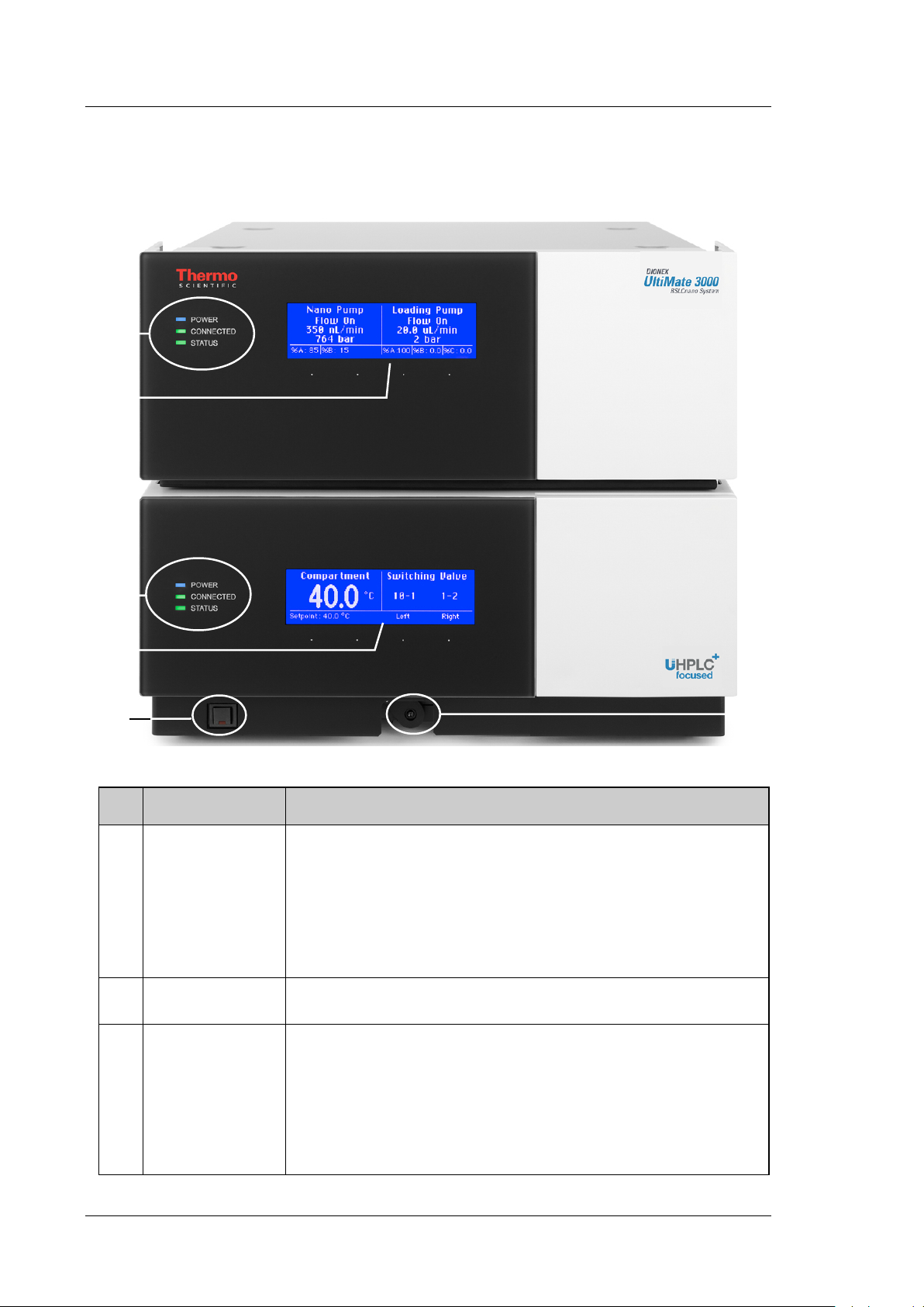
2.4 Front Panel Elements
Fig. 1: Front panel view (here NCS-3500RS)
No. Element Function
1
2 Lever Moves the valve actuators or, if already installed, the column switching
3 Display Shows information about the pump (upper display) and about the column
Standby button Switches the module to Standby mode (the LED is lighted).
To cancel Standby mode and resume operation, press the Standby button
again (the LED is not lighted).
Notes:
To allow the module to change the mode, press and hold the Standby
button for at least one second.
If you switch a module to which a SRD-3x00 Solvent Rack is connected
to the Standby mode, the Solvent Rack, too, will be set to Standby mode.
valves toward the front (→ page 78).
compartment (lower display):
- Status screen (→ page 85)
- Functions and menus (→ pages 94 and 96)
In addition, the following information appears on the pump display:
- General information upon power-up of the module (→ page 85)
- Messages (→ page 147)
Page 22 Operating Instructions
Page 31

No. Element Function
UltiMate 3000 Series:
NCS-3500RS and NCP-3200RS
4
Pump and column compartment status LEDs
Power The LEDs are blue when the module power is on.
Connected The LEDs are green when the module is connected in Chromeleon.
Status Status LED (pump module)
The LED is green when the pump is ready for operation.
The LED is red when an error has been detected, for example, a leak.
Status LED (column compartment)
The LED is green when the column compartment has reached the target
temperature.
The LED is orange when the column compartment has not yet reached the
target temperature or when the door is open.
The LED is red when an error has been detected, for example, a leak.
Operating Instructions Page 23
Page 32

UltiMate 3000 Series:
1
2
3
4
5
6
7
NCS-3500RS and NCP-3200RS
2.5 Rear Panel
Fig. 2: Rear panel view
No. Description
1
2
3
4
5
6 USB hub (3 USB ports, for USB 2.0 or 1.1)
7 USB port (USB 2.0 or 1.1)
Power switch (→ page 25)
Fuse cartridge (→ page 25)
Main power receptacle (→ page 42)
Digital I/O ports (→ page 25)
for communication with external devices, for example, a mass spectrometer
Solvent Rack port for connection of a SRD-3x00 Solvent Rack (→ page 25)
Depending on the UltiMate 3000 system configuration, for connection of one UltiMate 3000
system module each or for connection of one USB hub each (→ page 25).
for connecting the module to the Chromeleon computer (→ page 25)
Page 24 Operating Instructions
Page 33

UltiMate 3000 Series:
NCS-3500RS and NCP-3200RS
2.5.1 Power Switch
The main power switch is on the rear panel. The main power switch is used to turn the
device on or off.
2.5.2 Fuse Cartridge
The fuse cartridge contains two slow-blow fuses rated at 2 A (NCP-3200RS) or 4 A (NCS3500RS). For information about how to change the fuses, see page 216.
2.5.3 USB Port
The Chromeleon Chromatography Management System can use a USB (= Universal Serial
Bus) connection to control the module. Data is transferred digitally by means of the
appropriate USB cable (→ page 41).
You can use the internal USB hub (→ Fig. 2, no. 10) to connect three other modules in the
UltiMate 3000 product line, depending on the configuration of the UltiMate 3000 system, or
three external USB hubs.
Important: Thermo Fisher Scientific recommends using these USB ports only for
connections to Dionex instruments. Thermo Fisher Scientific cannot
guarantee correct functioning if third-party instruments are connected.
Important: Thermo Fisher Scientific recommande d'utiliser les ports USB
uniquement pour les raccordements aux instruments Dionex. Thermo
Fisher Scientific ne peut garantir le bon fonctionnement si les
instruments d'autres fabricants sont raccordés.
For information about how to connect the module to the Chromeleon computer, see
sections 3.4.1 and 3.4.2 (→ page 41).
2.5.4 Digital I/O
The digital I/O ports on the module provide two inputs and two relay outputs that can be
used to exchange digital signals with external devices. For more information, see page 42.
For information about the functions of the connector pins and pin assignment, see page 255.
2.5.5 Solvent Rack
Use this port to connect a SRD-3x00 Solvent Rack with integrated vacuum degasser
(→ page 20) to the module.
For information about the pin assignment of the Solvent Rack port, see page 256. For
information about how to install and operate the Solvent Rack, see the Solvent Rack manual.
Operating Instructions Page 25
Page 34

UltiMate 3000 Series:
6 3 2
1 7 5
4
NCS-3500RS and NCP-3200RS
2.6 Interior Components
Fig. 3: Interior components (here NCS-3500RS with Classic flow meter)
No. Description
1 NCS-3500RS only
Column compartment, here with one column switching valve (detailed view → page 229)
2 Pump module with
3
4
5
6
7 NCS-3500RS only
No. Description
NC pump (detailed view → page 220)
Detector of rear seal wash system (→ page 29)
Peristaltic pump of the seal wash system (→ page 29)
Flow meter of the NC pump (→ page 30)
Loading pump (detailed view → page 226)
Page 26 Operating Instructions
Page 35

UltiMate 3000 Series:
Capillary passage
in the pump module
NCS-3500RS and NCP-3200RS
2.7 Fluid Connections
The fluid components are located behind the front panel doors of the pump module and
column compartment. The module is designed to provide easy access to the fluid
components.
Pump Module
Tilt the front cover of the pump module upward. The open front panel locks in the topmost
position. Observe the information under Important further down in this section.
Two passages in the enclosure bottom of the pump module facilitate routing the capillaries to
the modules that are located below the pump module, for example, the column compartment,
and ensure the shortest possible connection.
Fig. 4: Capillary passage in the pump module
Column Compartment
Unlock the front panel door as shown in the picture. The door tilts downward. To close the
column chamber, tilt the front panel upward. The door locks automatically.
Fig. 5: Unlocking the front panel door
Important: The open front panel doors of the pump and column compartment
are not designed to carry weight. Therefore, you should not place
any objects on the open doors.
When lifting or moving the module, always lift by the bottom or
sides of the module. Do not lift the module by the front panel door.
This may damage the door.
Important: Ne placez aucun objet lourd sur les portes ouvertes des panneaux
avant. Ceci peut endommager les portes.
Lorsque vous soulevez ou déplacez l'instrument, saisissez-la toujours
par les côtés de l'instrument. Soulever l'instrument par le panneau
avant risque d'endommager les portes des panneaux avant.
Operating Instructions Page 27
Page 36

UltiMate 3000 Series:
NCS-3500RS and NCP-3200RS
When connecting the capillaries and routing them to other system modules, observe the
general information in section 4.2 (→ page 57). For more information about the liquid flow
paths in the module, see section 8 (→ page 219).
Page 28 Operating Instructions
Page 37

UltiMate 3000 Series:
NCS-3500RS and NCP-3200RS
2.8 Pump Module
The following sections provide a brief overview of the key features of the pump module.
2.8.1 Rear Seal Wash System
The pump module is equipped with an active rear seal wash system. Rear seal washing
helps avoiding damages to the pistons, piston seals, and support rings, and thus prolongs
the seal lifetime.
The rear seal wash system consists of a peristaltic pump, a detector, and a reservoir containing
seal wash solution. The wash solution passes the individual components as shown in Fig. 6.
No. Description
1 Seal wash reservoir
2 Peristaltic pump
3 Peristaltic tubing
4 + 5 Pump head, NC pump
6 Pump head, loading pump
7 Detector of seal wash system
8 To waste
Fig. 6: Rear seal wash system (here in the NCS-3500RS)
(The arrows indicated the flow path of the wash solution through the pump.)
For information about how to set up the rear seal wash system, see page 67. For more
information about how to operate the pumps with rear seal washing, see section 5.5.7
(→ page 122).
Operating Instructions Page 29
Page 38

UltiMate 3000 Series:
NCS-3500RS and NCP-3200RS
2.8.2 Flow Meter
The flow meter, which is located above the pump heads of the NC pump, controls the
required partial flows of the two solvent channels so that the selected target flow and the
selected solvent composition are reliably met. Two types of flow meters are available:
• ProFlow flow meter with thermal flow sensors, for nano LC (flow connections overview
→ page 31)
• Classic flow meter with flow selectors, for either capillary LC or micro LC (flow
connections overview → page 31)
The following flow meters and selectors are available for different flow ranges:
Description Part No.
ProFlow flow meter for nano LC (50 – 1500 nL/min), with
6041.7850
thermal flow sensors
Note: Operation of the module with a ProFlow flow meter
requires a suitable firmware and Chromeleon version. For
details, contact Thermo Fisher Scientific sales organization.
Classic flow meters with flow selector, for:
Capillary LC (0.5 – 10 µL/min) 6041.7902A
Micro LC (5 – 50 µL/min) 6041.7903A
Flow selectors for Classic flow meters:
♦ Flow selector for capillary LC (0.5 – 10 µL/min)
♦ Flow selector for micro LC (5 – 50 µL/min)
6041.0003
6041.0014
Note:
♦ To modify from a ProFlow flow meter to a Classic flow meter or vice versa,
exchange the complete flow meter.
♦ To modify the flow range of a Classic flow meter, install the respective flow
selector for capillary or micro LC.
For more information about the flow meter, see pages 110 and 222.
For information about how to replace a flow meter or a flow selector (Classic flow meters
only) for a different flow range, see section 7.7 (→ page 202).
Page 30 Operating Instructions
Page 39

UltiMate 3000 Series:
1 3 2 4 5
NCS-3500RS and NCP-3200RS
ProFlow Flow Meter Flow Connections
Fig. 7: ProFlow flow meter
No. Description For capillary connection…
1 Flow meter inlet (from left pump head)
With built-in inline filter
2 Flow meter inlet (from right pump head)
With built-in inline filter
3 Flow meter outlet (pump outlet) From flow meter to autosampler
From left pump head to flow meter
From right pump head to flow meter
Tip: Operation of the module with a ProFlow flow meter requires a suitable
firmware and Chromeleon version.
Classic Flow Meter Flow Connections
Fig. 8: Classic flow meter
No. Description No. Description
1 Flow meter inlet (from left pump head) 4 Capillary from right pump head to flow
meter
2 Capillary from left pump head to flow meter 5 Flow meter inlet (from right pump head)
3 Flow meter outlet (pump outlet)
Operating Instructions Page 31
Page 40

UltiMate 3000 Series:
Purge screw
right head (channel B)
Purge screw
left head (channel A)
Purge outlet
right head (channel B)
Purge outlet
left head (channel A)
Pressure transducer
for system pressure
Connection port for
inline filter
Purge screw
Connection port for
pump head capillary
Purge outlet
NCS-3500RS and NCP-3200RS
2.8.3 Leak Sensor
A leak sensor is installed inside the pump module. Leak detection is enabled as a standard
when the module is shipped.
If liquid collects in the drip tray under the fluid connections, the leak sensor reports a leak.
The Status LED on the front panel door turns red. A beep sounds and a message appears on
the pump display and in the Chromeleon Audit Trail. When the leak sensor reports a leak,
eliminate the cause for the leakage and dry the leak sensor (→ page 177).
For more information, see section 5.5.9 (→ page 124).
2.8.4 Purge Valve
NC pump
Both pump heads (solvent channels) of the NC pump have their own purge valve with purge
screw and purge outlet. The purge screw and purge outlet are located in the flow meter above
the pump head to which they belong.
Fig. 9: Purge valves of the NC pump (here: Classic flow meter)
Loading pump
The loading pump has a purge unit that comprises the purge valve with purge screw and
purge outlet. In addition, the purge unit comprises the pressure transducer of the system
pressure.
Fig. 10: Purge unit
Page 32 Operating Instructions
Page 41

UltiMate 3000 Series:
Inline filter
NCS-3500RS and NCP-3200RS
2.8.5 Inline Filter (Loading Pump)
The loading pump has an inline filter that is located below the pump head. The filter
volume is 10 µL. The filter frit is a titanium frit with a porosity of 2 µm.
Fig. 11: Inline filter (loading pump)
Operating Instructions Page 33
Page 42

UltiMate 3000 Series:
NCS-3500RS and NCP-3200RS
2.9 Column Compartment
The following sections provide a brief overview of the key features of the column
compartment.
2.9.1 Gas and Humidity Sensors
A gas sensor and a humidity sensor are installed inside the column compartment. The
sensors detect any gas or humidity that may accumulate in the column chamber. You can
adjust the sensitivity of the gas sensor and the humidity sensor in Chromeleon or on the
front panel display (→ page 130).
When a certain concentration of gas or humidity is reached inside the column compartment
(while the door of the column chamber is closed), the related sensor is activated and the
Status LED on the front panel door turns red. A message appears on the front panel display
and in the Chromeleon Audit Trail. It depends on the sensor settings whether a beep sounds in
addition to alert you (→ page 130).
When a sensor reports excessive gas or humidity, find and eliminate the source for the
leakage (→ page 178).
2.9.2 Column Switching Valves
The column compartment can be equipped with one or two column switching valves
(→ page 19) and thus, provides highest flexibility for all applications that required
different columns at similar temperatures. The switching valves are installed in the column
chamber, where they are brought to the preferred temperature together with the columns.
For information about how to connect the components to the column switching valve, see
page 82.
2.9.3 Column Identification System (Column ID)
The column compartment is fitted with an electronic column identification system (column
ID) that allows you to store column-specific information on a column-ID chip card. This
information provides a GLP-compliant overview of the column status. The chip card is
connected to the column for the column life cycle. Column identification is supported for
up to four columns simultaneously.
The information on the column ID chip card is continuously updated and can be reviewed at
any time in Chromeleon, as long as the column and chip card are installed in the column
compartment. For more information about the column ID, see page 129.
Page 34 Operating Instructions
Page 43

UltiMate 3000 Series:
NCS-3500RS and NCP-3200RS
2.10 Operation from Chromeleon
The module can be controlled by the Chromeleon Chromatography Management System.
To do so, an appropriate Chromeleon version and license are required.
Two modes of software control are available:
• Direct Control
With direct control, you select operating parameters and commands in the Commands
(F8) dialog box. Direct commands are executed as soon as they are entered. For routine
operation, most parameters and commands are available also on a control panel. For
more information about direct control, see page 89.
• Automated Control
With automated control, you create a program (or PGM File). This is a list of control
commands, executed in chronological order, for automated operation of the module. You
can create programs automatically with the software wizard or manually by editing an
existing program. For more information about automatic control, see page 92.
Tip: All software details in this manual refer to Chromeleon 6.80.
If you want to operate the module from Chromeleon 7 (availability with
Chromeleon 7.1 and later), refer to the following documents for information
about how to perform the related processes in Chromeleon 7 (all documents are
included in the Chromeleon 7 shipment):
• Chromeleon 7 Help—provides extensive information and comprehensive
reference material for all aspects of the software.
• Quick Start Guide—describes the main elements of the user interface and
guides you step-by-step through the most important workflows.
• Reference Card—provides a concise overview of the most important
workflows.
• Installation Guide—provides basic information about module installation
and configuration. For specific information about a certain module, refer
to the Chromeleon 7 Instrument Configuration Manager Help.
Note the following:
• Chromeleon 7 terminology is different from the terminology used in
Chromeleon 6.80. For details, refer to the 'Glossary - Chromeleon 7,'
which is available in the Documents folder of your Chromeleon 7
installation.
• Chromeleon 7 may not yet support all functions supported in
Chromeleon 6.80.
Operating Instructions Page 35
Page 44

UltiMate 3000 Series:
NCS-3500RS and NCP-3200RS
2.11 System Wellness, Predictive Performance, and Diagnostics
System Wellness monitors the health of the module. Therefore, the module supports
several performance and reliability features that can help you detect small problems before
they turn into big ones:
• Internal monitoring of all mechanical operations
• Automatic self test upon power up
• Active rear seal wash system (→ page 29)
• Leak sensor in the pump module to detect liquid leaks (→ page 32)
• Leak sensors in the column compartment to detect excessive gas and/or humidity
(→ page 34)
• Electronic column identification system to provide a GLP-compliant overview of the
column status (→ page 34)
When an error is detected, the Status LED on the related front panel door is red, a beep
sounds, and a message appears on the pump display (→ page 147).
When the module is operated from Chromeleon, additional features are available:
• Functions for estimating the lifetime of consumables and monitoring and recording
service and (re)qualification information (= predictive performance; → page 132)
• Diagnostics functions for checking the performance of certain module components
(→ page 134).
Page 36 Operating Instructions
Page 45

UltiMate 3000 Series:
NCS-3500RS and NCP-3200RS
3 Installation
3.1 Facility Requirements
The installation site must meet the following requirements:
• The main power switch and the main power receptacle are on the rear panel. Make sure
that
♦ Free and unrestricted access to the main power switch is ensured at all times.
♦ The power cord of the device can be easily reached and disconnected from the
power line at all times. Provide sufficient space behind the device to unplug the
cable.
• Make sure that the installation site meets the power and environmental specifications
listed in the Technical Information section (→ page 235).
• Install the module in the laboratory on a stable surface. Make sure that the position is
horizontal and free of vibrations.
• Make sure that the surface is resistant to solvents.
• Avoid locations with extreme changes in temperature.
• Also, avoid locations with extreme direct sunlight and high humidity.
• Allow sufficient clearance behind and to the sides of the module for ventilation and do
not place any objects between the module and the module located below it in the system
stack
3.2 Unpacking
All electrical and mechanical components of the module are carefully tested before the
module is shipped from the factory. After unpacking, inspect the module for any signs of
mechanical damage that may have occurred during transit.
Tips: Immediately report any shipping damage to both, the incoming carrier and
Thermo Fisher Scientific. Shipping insurance will compensate for the damage
only if reported immediately.
Keep the original shipping container and packing material. They will provide
excellent protection for the module in case of future transit. Shipping the
module in any other packaging automatically voids the product warranty.
Operating Instructions Page 37
Page 46

UltiMate 3000 Series:
NCS-3500RS and NCP-3200RS
1. Only NCS-3500RS
Place the shipping container on the floor, remove the container cover, and take out the
spacer box. The NCS packaging box may remain in the bottom part of the shipping
container.
2. Open the packaging box of the module, and remove the accessories kit and power
cord. Some accessories may be shipped in a separate box.
3. Grasp the module by the sides. Slowly and carefully, pull the module out of the
shipping container and place it on a stable surface.
Important: To prevent the module from falling, grasp the module by the sides,
and then lift the module together with the foam spacers out of the
shipping container. Do not lift the module by the foam spacers and
not by the front panel doors.
A team effort is required to lift or move the NCS-3500RS. The
NCS-3500RS is too heavy and/or bulky for one person alone to lift
or move safely.
Important: Afin d'empêcher l'instrument de tomber, saisissez-la par les côtés.
Ne soulevez l'instrumente à l’aide du matériau d'emballage ou par
les portes des panneaux avants.
Le NCS-3500RS et lourd et encombrant. Par conséquent, vous ne
devriez pas soulever l'instrument seul.
4. Remove the foam spacers, and then remove the polythene packaging.
5. Tilt the front panel of the pump module upward and remove the foam inserts securing
the front panel door during shipment.
6. Only NCS-3500RS
Unlock the front panel door of the column compartment (→ page 27) and remove the two
foam inserts securing the valve drives during shipment.
7. Before connecting the module to the power source, wait approximately four hours to
allow the instrument to come to room temperature and to allow any condensation that
might have occurred during shipping to evaporate.
After four hours, check the module; if condensation still exists, allow the module to
continue to warm up (without connecting it to the power source) until the condensation is
completely gone.
Page 38 Operating Instructions
Page 47

UltiMate 3000 Series:
NCS-3500RS and NCP-3200RS
3.3 Positioning the Module in the UltiMate 3000 RSLCnano System
If the module is part of an UltiMate 3000 RSLCnano system, stack the individual modules
(→ Fig. 12) and interconnect them on the rear panel (→ Fig. 13). The arrangement of the
system modules depends on the application.
For information about how to arrange and set up an RSLCnano System, refer to the
"UltiMate 30000 RSLCnano - Standard Applications" system manual. The system manual
is shipped with the module.
Solvent Rack
(SRD-3400)
NCS-3500RS
Detector
(VWD-3400RS)
Autosampler
(WPS-3000TPL RS)
Fig. 12: Module arrangement for an UltiMate 3000 RSLCnano system (example)
Operating Instructions Page 39
Page 48

UltiMate 3000 Series:
NCS-3500RS and NCP-3200RS
SRD-3400
Optional
Digital I/O for
MS connection
NCS-3500RS
VWD-3400RS
WPS-3000TPL RS
Fig. 13: Example for the rear panel connections on an UltiMate 3000 RSLCnano system
Thermo Fisher Scientific recommends interconnecting all modules of the RSLCnano
system and then connecting the system to the Chromeleon computer with only one
connection. For systems with a VWD-3400RS, use only the hub on the NCS-3500RS or
NCP-3200RS, respectively. For systems with a DAD-3000RS or MWD-3000RS detector,
you can use only the hub on the detector.
Apart from the Solvent Rack, all modules of the UltiMate 3000 RSLCnano system can be
connected also separately to the Chromeleon computer by using the USB port on the rear
panel of the module.
Page 40 Operating Instructions
Page 49

UltiMate 3000 Series:
NCS-3500RS and NCP-3200RS
3.4 Connecting the Module
3.4.1 General Information
If you want to operate the module from Chromeleon
Before you connect the module to the USB port on the Chromeleon computer and turn on the
module power, verify that Chromeleon is installed on the computer and that the license code
is entered. Only if you install Chromeleon first, the USB driver for the module is
automatically loaded and the Windows® operating system can detect the module when the
power is turned on.
3.4.2 Connecting the USB Cable
Connect the module to the Chromeleon computer by using the USB ports on the rear panel
(→ Fig. 2, page 24). Select one of the following alternatives:
• Connect the module directly to the USB port on the Chromeleon computer.
• Connect the module to the computer by using an external USB hub. (However, this may
be the source for communication problems, depending on the quality of the hub.)
Tip: The USB standard limits the USB cable length to 5 meters. Each USB device
can be separated from the PC or next USB hub by no more than 5 meters
To ensure trouble-free operation, use only these cables for the connection (both cables are
provided in the accessories kit for the module):
USB Cable Part No.
USB cable, type A to type B, high speed USB 2.0
6911.0002
(cable length: 5 m)
USB cable, type A to type B, high speed USB 2.0
6035.9035
(cable length: 1 m)
Operating Instructions Page 41
Page 50

UltiMate 3000 Series:
NCS-3500RS and NCP-3200RS
3.4.3 Connecting the Power Cord
Use the power cord shipped with the module to connect the module to the main power
source. Connect the power cord from the main power receptacle on the rear panel
(→ Fig. 2, page 24) to a grounded power source. No manual adjustment is required to
adapt the line voltage to local voltage requirements.
Warning: Never use a power cord other than the power cords provided for the
device.
Do not use multiple sockets or extension cords. Using defective
multiple sockets or extension cords may cause personal injury or
damage to the device.
Avertissement: Utilisez uniquement les cordons d’alimentation électrique spécifique
à l’instrument.
N'utilisez pas des blocs multiprise ou des câbles prolongateurs. Cela
pourrait entraîner des blessures corporelles ou endommager
l'instrument.
3.4.4 Connecting a Solvent Rack
If the UltiMate 3000 system includes a SRD-3x00 Solvent Rack, connect the Solvent
Rack port on the rear panel of the module to the 15-pin D-Sub connector on the rear panel
of the Solvent Rack. The appropriate connection cable is included in the accessories kit of
the Solvent Rack.
3.4.5 Connecting Devices (Mass Spectrometers) to the Digital I/O-Port
To connect a device, for example, a mass spectrometer, to a digital I/O port on the rear
panel of the module, use a 6-pin mini-DIN signal cable (part no. 6000.1004). The cable is
available from Thermo Fisher Scientific.
1. Plug the 6-pin connector of the mini-DIN cable into the Digital I/O port 1 (or 2). For
information about the functions of the connector pins and pin assignment, see
page 255.
2. For each relay output or digital input to be used, connect the appropriate signal wire
and ground wire to the corresponding connectors on the device (→ documentation
provided with the device).
For example, if you want to use a relay output to control a mass spectrometer, use the
wires 5 (brown) and 6 (white).
3. When setting up the module in the Chromeleon Server Configuration program
(→ page 46), select the corresponding relay outputs on the Relays page and the digital
inputs on the Inputs page.
The relay outputs and digital inputs are then available in Chromeleon, for example, in the
Commands dialog box under PumpModule, and can be programmed as required.
Page 42 Operating Instructions
Page 51

UltiMate 3000 Series:
NCS-3500RS and NCP-3200RS
3.5 Setting Up the Module in Chromeleon
This section provides brief instructions for setting up the module in Chromeleon. For
details, see the Chromeleon Help.
Tip: When the module is connected to the Chromeleon computer, verify that the
Chromeleon software is installed before turning on the power to the module for
the first time. Only then, the USB driver for the module is automatically loaded
and the Windows operating system can detect the module when the power is
turned on.
3.5.1 Loading the USB Driver for the Module
1. Turn on the computer power, if it is not already on.
2. Under Windows Vista® (Windows® XP, Windows® 7, or Windows® Server 2008) log
on as a
♦ Local administrator if the computer is a local computer.
♦ User with local computer administrator privileges if the computer is a network
computer.
3. Open the Chromeleon Server Monitor program by double-clicking the Chromeleon
Server Monitor icon on the Windows taskbar.
If the Server Monitor icon is not on the taskbar, click Start on the taskbar, point to
Programs (or All Programs, depending on the operating system), point to Chromeleon,
and then click Server Monitor.
4. Click Start to start the server.
5. Click Close to close the Server Monitor window. The Server Monitor icon
appears on the taskbar.
Tip: Clicking the Quit Monitor button quits (exits) the Server Monitor
program, but does not stop the server. To stop the server, click Stop.
6. Turn on the main power switch on the rear panel of the module.
7. Depends on the operating system
Windows Vista, Windows 7, and Windows Server 2008
will automatically detect the new module and perform the USB installation. If Windows
fails to detect the module and launches a wizard instead, this indicates that you connected
the module to the computer and turned on the power for the first time before you installed
Chromeleon.
Operating Instructions Page 43
Page 52

UltiMate 3000 Series:
NCS-3500RS and NCP-3200RS
To resolve the problem:
a) Click Cancel to exit the wizard.
b) Turn off the power to the module.
c) Install Chromeleon.
d) Turn on the power to the module. Windows will now detect the module and install the
USB software for the module automatically.
Windows XP
will automatically detect the new module and launch the Found New Hardware
Wizard, which guides you through the USB installation. Select the following options:
a) If asked whether Windows can connect to Windows Update to search for software,
select No, not this time.
b) Accept the default option (Install the software automatically) and click Next>.
c) Click Finish when the wizard reports that the software for the module has been
installed.
If Windows fails to detect the module and a message box asks for a USB configuration
file (cmwdmusb.inf), this indicates that you connected the module to the computer and
turned on the power for the first time before you installed Chromeleon. To resolve the
problem:
a) Click Cancel in the Windows message box.
b) Turn off the power to the module.
c) Install Chromeleon.
d) Turn on the power to the module. Windows will now automatically detect the module
and launch the Found New Hardware Wizard.
Page 44 Operating Instructions
Page 53

UltiMate 3000 Series:
NCS-3500RS and NCP-3200RS
3.5.2 Installing the Module
After the USB software for the module has been installed (→ page 43), install and
configure the module in Chromeleon:
1. Start the Chromeleon Server Monitor and the Chromeleon server if they are not yet
running (→ page 43).
2. Start the Server Configuration program in Chromeleon.
Click Start on the taskbar. Point to Programs (or All Programs, depending on the
operating system), point to Chromeleon, and then click Server Configuration.
3. If necessary, click the plus sign next to the server name to display the items
underneath.
4. Select the timebase to which the module will be assigned, or create a new timebase (on
the Edit menu, click Add Timebase).
5. Open the Add device to timebase dialog box. To do so, click Add Device on the Edit
menu or right-click the timebase and click Add Device on the menu.
6. On the Manufacturers list, click Dionex HPLC: UltiMate 3000 and on the Devices
list, click the module you want to add, for example, NCS-3500RS Nano/Cap System.
7. The configuration pages for the module are opened. On each configuration page,
verify that the settings are correct and select additional settings if needed. For a
description of the pages, see section 3.5.3.1 (→ page 46).
8. On the File menu, click Save Installation and then close the Server Configuration
program.
Operating Instructions Page 45
Page 54

UltiMate 3000 Series:
NCS-3500RS and NCP-3200RS
3.5.3 Configuring the Module
3.5.3.1 Initial Installation
On each configuration page for the module, check and change the settings if necessary and
select additional settings if needed. You may reopen the configuration pages later again to
change the settings (→ page 53).
Tip: Changing the settings for a specific application in the Commands dialog box,
in a program file (PGM), or on a control panel will not change the settings on
the configuration pages.
For additional information about a page, click Help.
General Page
Display general information about the module:
Fig. 14: General page
• Device Type
Indicates the device model.
• Enable Virtual Mode
This check box should be cleared because Chromeleon only simulates the functions of
the module when the virtual mode is active. If the Virtual Mode is enabled, the Module
Address box will be unavailable.
• Module Address
Select the address of the module if necessary. Click Browse and then double-click the
module that you want to use on the Device List. The address is automatically entered in
the Module Address box. The button appears dimmed if the virtual mode is enabled.
Page 46 Operating Instructions
Page 55

UltiMate 3000 Series:
NCS-3500RS and NCP-3200RS
• Download
Click the Download button to transfer the firmware version available for the module in
Chromeleon to the module. The button appears dimmed if the virtual mode is enabled.
The module is shipped with the most recent firmware version. If a firmware update is
ever required, follow the steps in section 7.14 (→ page 217).
Pumps Page (NCS-3500RS) or Devices Page (NCP-3200RS)
Displays the names used to identify the pump module and pumps in Chromeleon, and sets
whether the degasser of a SRD-3x00 Solvent Rack can be operated via the pump module.
Fig. 15: Pumps page
• Main Device
♦ Name (default name PumpModule)
Displays the name used to identify the pump module in the installation environment
and in the Chromeleon client. Under PumpModule, the following commands and
properties are displayed, for example, in the Commands dialog box (→ page 89):
♦ General properties and commands related to the entire pump module, such as
the commands and properties for the seal wash system, leak detection, or the
degasser in a SRD-3x00 Solvent Rack that is connected to the module.
♦ Specific groups of properties and commands for the pumps of the pump
module. These commands and properties appear under the pump name
(→ Loading Pump Device and NC Pump Device further down in this section).
To control the pump module with the existing control panels, accept the default
name. If you enter a different name, you may have to re-link the controls on the
control panels and edit the device name of the pump module in the program files.
Operating Instructions Page 47
Page 56

UltiMate 3000 Series:
NCS-3500RS and NCP-3200RS
♦ Degasser Control
Click the arrow of the Degasser Control box and select External on the list if a
SRD-3x00 Solvent Rack is connected to the module. With this setting, the degasser
in the Solvent Rack can be operated and monitored via the pump module. The
related commands and properties are available, for example, in the Commands
dialog box (under PumpModule).
In all other cases, select None.
• Loading Pump Device, NC Pump Device (NCS-3500RS), or
Pump Device (NCP-3200RS)
(default names LoadingPump, NC_Pump (NCS-3500RS and NCP-3200RS))
Under this name, specific groups of properties and commands are listed in the
Commands dialog box for the related pump. There you can set, for example, the flow
rate and the partial flows, change the upper and lower pressure limits, and start a purge
cycle.
To control the pump with the existing control panels, accept the default name. If you
enter different names, you may have to re-link the controls on the control panels and edit
the names in the program files.
Limits Page
The loading pump and the NC pump of the NCS-3500RS have separate Limits pages,
displaying the allowed ranges for the flow rate and pressure of the related pump. You can
change the upper and lower limits within the allowed ranges. In addition, you can change the
pressure unit and, for the loading pump, change the flow unit.
Fig. 16: Limits page (here for the loading pump)
Page 48 Operating Instructions
Page 57

UltiMate 3000 Series:
NCS-3500RS and NCP-3200RS
• Flow
Shows the allowed flow range.
Enter a new value in the Minimum and/or Maximum box to change the limits for the
flow rate within the allowed range.
On the Limits (Loading) page, under Flow Unit, you can select the unit in which the
loading pump flow is displayed (µl/min or ml/min).
• Pressure
Shows the allowed pressure range.
Enter a new value in the Minimum and/or Maximum box to change the pressure limits
within the allowed range.
Click the arrow of the Pressure Unit box and select a different pressure unit (psi, bar, or
MPa) on the list if required.
These values are the absolute limits. Within these limits, you can set specific limits on a
control panel or in a program file.
Solvents Page
The loading pump and the NC pump of the NCS-3500RS have separate Solvents pages.
Check and change the number of solvents delivered by the pump and the solvent names if
necessary.
• Number of Solvents
Indicate how many solvents are delivered by the pump. The pump type determines how
many solvents can be delivered.
Pump Type Max. Number of Solvents
NC pump 2
Loading pump 3
• Solvent Names
Enter a name for each connected solvent. A solvent name can contain a maximum of
30 characters. The names of the solvents appear, for example, in the gradient display of
the online control panel and in the report.
Tip: Changing the solvent names on the Solvents page does not set up the flow
meter to operate properly with the respective solvent. Make sure that the
flow meter is also configured for the solvents that you use
(→ section 4.5.2, page 69).
Operating Instructions Page 49
Page 58

UltiMate 3000 Series:
NCS-3500RS and NCP-3200RS
Oven / Valves Page
Displays the name used to identify the column compartment in Chromeleon and sets whether
the temperature is recorded as a separate channel and which column switching valves are
installed.
Fig. 17: Oven / Valves page
• Oven Device Name (default name ColumnOven)
Displays the name used to identify the column compartment in the installation
environment and in the Chromeleon Client program. To control the column compartment
with the existing control panels, accept the default name. If you enter a different name,
you may have to re-link the controls on the control panels and edit the name of the
column compartment in the program files.
• Temperature Channel (default name ColumnOven_Temp)
The Use Channel check box is selected by default. Accept this setting if you want to
record the temperature of the column compartment as a separate channel (→ page 131).
The name specified in the Channel Name text box is used to identify the temperature
channel in the installation environment and in the Chromeleon Client program. Accept
the default name. If you enter a different name, you may have to re-link the controls on
the control panels and edit the channel name in the program files.
• Left Valve and Right Valve
Indicate which type of column switching valve is installed. Check and change the settings
if necessary.
Page 50 Operating Instructions
Page 59

UltiMate 3000 Series:
NCS-3500RS and NCP-3200RS
Columns Page
The Columns page shows all columns that are available for column monitoring (→ page 34).
Fig. 18: Columns page
Select the columns for which you want to use column identification by the check box in the
Enabled column. If a check box is cleared, the column will not be available in
Chromeleon. The Name column displays the name used to identify the column in the
installation environment and in the Chromeleon Client program. To use existing control
panels, accept the default name.
To change a column name, overwrite the existing name directly in the corresponding line. If
you enter a different name, you may have to re-link the controls on the control panels and edit
the column name in the program files.
The information about the column is continuously updated and can be reviewed at any time in
Chromeleon (→ page 129).
Signals Page
The Signals page lists all available signals. Select a check box to enable the signal. If a
check box is cleared, the signal will not be available in Chromeleon. To change a signal
name or the scaling factor, overwrite the existing entry directly in the corresponding line.
The NC pump pressure signal is selected by default. Accept this setting if you want to record
the column pressure of the NC pump. If a signal channel is selected, Chromeleon generates
the channel for data acquisition.
Depending on the flow meter that is installed, make sure that the corresponding signals are
selected in order to gain information from the signal channels on the respective flow meter
performance.
For more information, see section 5.5.6 (→ page 121).
Operating Instructions Page 51
Page 60

UltiMate 3000 Series:
NCS-3500RS and NCP-3200RS
Relays Page
The Relays page lists all available relays. Select a check box to enable the relay. If a check
box is cleared, the relay will not be available in Chromeleon. To change a relay name,
overwrite the existing name directly in the corresponding line. For more information about
the relays, see page 25.
Inputs Page
The Inputs page lists all available remote inputs. Select a check box to enable the remote
input. If a check box is cleared, the input will not be available in Chromeleon. To change an
input name, overwrite the existing name directly in the corresponding line.
Flowmeter Page
The Flowmeter page shows the flow meter installed in the NC pump.
The settings that are displayed depend on the flow meter that is installed. When a module is
selected under Module Address on the General page, the flow meter type is detected
automatically and displayed on the Flowmeter page.
Flowmeter Type
To be able to use a certain solvent with the NC pump, consider the correct setting for the
respective flow meter:
• ProFlow flow meter
With a ProFlow flow meter, the flow meter must know the solvent type.
The solvent list shows the pre-defined and user-defined solvents for each pump block
channel.
• Classic flow meter
With Classic flow meters, the solvent viscosity must be known.
A viscosity list shows the pre-defined and user-defined solvent viscosity values for the
flow meter.
• Update button
After you have changed the solvent or viscosity list, click the Update button to refresh
the flow meter configuration.
Solvent List (ProFlow) / Viscosities (Classic)
• The solvent list (ProFlow flow meter) or the viscosities (Classic flow meters) of the most
common solvents is available in Chromeleon as a default (→ page 69).
• If the solvent type (ProFlow flow meter) or the viscosity (Classic flow meters) of the
solvent that you are using is not yet available in Chromeleon, see section 5.5.3 Adding
Solvents to the Flow Meter Configuration (→ page 114).
Page 52 Operating Instructions
Page 61

UltiMate 3000 Series:
NCS-3500RS and NCP-3200RS
3.5.3.2 Changing the Configuration Properties
To change the standard configuration settings, reopen the configuration pages.
1. Start the Server Configuration program (→ page 45).
2. Right-click the module in the timebase and click Properties on the menu.
3. Change the settings as needed. For a description of the pages, see section 3.5.3.1
(→ page 46).
4. To save the configuration, click Save Installation on the File menu and then close the
Server Configuration program.
Operating Instructions Page 53
Page 62

UltiMate 3000 Series:
NCS-3500RS and NCP-3200RS
Page 54 Operating Instructions
Page 63

UltiMate 3000 Series:
NCS-3500RS and NCP-3200RS
4 Preparation for Operation (Startup)
4.1 Overview
Important: The module is filled with 2-propanol when being shipped from the
factory. During initial operation of the module, make sure that the
solvents used are miscible with 2-propanol. Otherwise, use an
appropriate intermediate solvent.
Important: L'instrument est stocké sous 2-propanol lorsqu'el est expédié depuis
l'usine. Lors du démarrage initial de l'instrument, assurez-vous que
les solvants utilisés sont miscibles. Dans le cas contraire, utilisez un
solvant intermédiaire approprié. Même d'infimes particules peuvent
endommager le système.
After you have unpacked, positioned and connected the module (→ sections 3.1 through
3.4, page 37 and following pages), prepare the module for operation:
1. If the RSLCnano system includes a SRD-3x00 Solvent Rack
Connect the 15-pin D-Sub port on the rear of the Solvent Rack with the Solvent Rack
port on the rear of the module (→ page 25).
2. If you want to connect a mass spectrometer to the module
Connect the Digital I/O port on the rear of the module with the appropriate port on the
mass spectrometer (→ page 42).
3. Connect the solvent reservoirs (→ page 62).
4. Connect drain tubing (→ page 65).
Important: If drain tubing is not connected, modules that are located below this
module in the UltiMate 3000 system stack, may suffer severe
damage from the liquid leaving the drain port.
Important: Si le drainage n'est pas attaché, il peut résulter des dommages par
des solvants aux modules qui se trouvent au-dessous de
l'instrument dans l'UltiMate 3000 système.
5. If you want to operate the module from Chromeleon
♦ Set up the module in Chromeleon if it is not already set up (→ page 43).
♦ If you want to operate the degasser of a SRD-3x00 Solvent Rack from Chromeleon,
verify on the Pump page of the Properties dialog for the module that Degasser
Control is set to External (→ page 47).
6. Turn on the power to the module (→ page 85).
Operating Instructions Page 55
Page 64

UltiMate 3000 Series:
NCS-3500RS and NCP-3200RS
7. Pump Module
a) Set up the seal wash system (→ page 67) and flush the system with the seal wash
solution (→ page 67).
b) This step depends on the flow meter that is installed:
♦ Classic flow meter
Specify the viscosity of the solvents used with the NC pump (→ page 69).
♦ ProFlow flow meter
Set the solvent types for the solvents used with the NC pump (→ page 69).
Keep in mind that the module can deliver exact flow rates and gradients only if the
viscosity (Classic flow meter) or solvent type (ProFlow flow meter) is set correctly.
c) Purge the pumps of the pump module (→ page 72).
d) Check and change the leak sensor setting if necessary (→ page 124).
e) Adjust the brightness and contrast of the front panel display if necessary
(→ page 125).
8. Column Compartment
a) Install the valves if required (→ page 78).
b) Install the separation columns (→ page 80).
c) Install a trap column if required for your application (→ page 82).
d) Establish the fluid connections between the columns and switching valves, as required
by your application. For information about how to connect the capillaries to the valve,
see section 4.6.4 (→ page 82).
e) Turn on temperature control if applicable and set the temperature setpoint
(→ page 127).
f) Activate column identification if applicable (→ page 129).
g) Check and change the sensitivity settings for the gas and humidity sensors if necessary
(→ page 130).
h) Adjust the brightness and contrast of the front panel display if necessary
(→ page 125).
9. Connect the module to the other modules of your RSLCnano system, as required by
your application. When connecting the capillaries, observe the general information on
page 57.
10. Before starting sample analysis, equilibrate the entire system (→ page 83).
Page 56 Operating Instructions
Page 65

UltiMate 3000 Series:
NCS-3500RS and NCP-3200RS
4.2 Capillaries and Capillary Routing
The following sections provide information about how to connect capillaries and route
them inside the module and to the other modules in your UltiMate 3000 system.
4.2.1 Connecting and Handling Capillaries
When connecting capillaries to the module, observe the following general precautions:
• Observe the precautionary statements for capillaries and capillary connections in
section 1.2.2 (→ page 5).
• Thermo Fisher Scientific recommends using Viper or nanoViper capillary connections
whenever possible.
• Only Viper or nanoViper capillaries with knurled screws must be connected to the flow
meter outlet.
Tip: Viper or nanoViper capillaries with torque toothing cannot be connected to
the flow meter outlet.
• When you connect capillaries, make sure that the connectors are free from contaminants.
Even minute particles may cause damage to the system.
• Different fitting systems are used in an UltiMate 3000 system. Therefore, install the
capillaries and fittings only at the positions for which they are intended.
• Use only the capillaries shipped with the module and original spare capillaries.
• Depending on the fitting connection, also observe the following:
♦ Viper connections - Depending on the Viper fitting:
Fig. 19: Viper fitting connections
(left: with knurled screw (example), right: with torque toothing)
Tips: You can reuse capillaries with Viper fitting connections also for a
different connection.
If the knurled screw is a black screw (as shown in Fig. 19), you can
remove it from the capillary and reattach it later again.
Operating Instructions Page 57
Page 66

UltiMate 3000 Series:
Tighten a connection by
using this side, with the arrow
on the tool pointing to the
left.
Tool on torque toothing
Tool on torque toothing
Loosen a connection by using this
side of the tool.
NCS-3500RS and NCP-3200RS
♦ Viper fitting with torque toothing (NCS-3500RS)
Loosen or tighten these Viper connections only with your hand and by using the
special installation tool (part no. 6040.2314). The installation tool is provided in
the accessories kit for the NCS.
When tightening a connection, first tighten the connection hand-tight. Then, use
the tool to tighten the connection further. Use the tool as shown in Fig. 20.
Tighten until you hear a click, indicating that the torque limitation has been
reached. Loosen a connection in the same way.
Fig. 20: Installation tool for Viper capillaries with torque toothing
If leakage is observed at the connection port, remove the capillary, clean the
capillary ends carefully by using a cloth or tissue wetted with isopropanol, and
reinstall the capillary. If the connection continues to leak, install a new Viper
capillary.
♦ Viper fitting with knurled screw
Loosen or tighten these Viper connections only by using the black knurled screw
and only with your hand (do not use tools). If you observe leakage on the
connection, tighten the screw a little further.
If leakage continues, remove the capillary, clean the capillary ends carefully by
using a cloth or tissue wetted with isopropanol, and reinstall the capillary. If the
connection continues to leak, replace the Viper capillary.
Page 58 Operating Instructions
Page 67

♦ Conventional fitting connections (non-Viper)
Do not over-tighten these fitting connections. If you observe leakage on the
connection, tighten a little further.
If leakage still exists, clean the connection port with a cleaning swab (part
no. 6040.0006). If this does not eliminate the problem, replace the capillary and/or
fitting.
To avoid increased dead volume or damage to the system and leakage, reuse fittings
and ferrules only for the same capillary connection.
UltiMate 3000 Series:
NCS-3500RS and NCP-3200RS
Operating Instructions Page 59
Page 68

UltiMate 3000 Series:
Preinstalled clips
NCS-3500RS and NCP-3200RS
4.2.2 Routing Capillaries
When routing capillaries in the module or to other system modules, observe the following
general information:
Pump Module
• Two passages in the enclosure bottom of the pump module (→ Fig. 4, page 27) facilitate
routing the capillaries to the modules that are located below the pump module and ensure
the shortest possible connection.
• Two clips are installed in the pump module, for example, to secure the solvent lines to
the interior front panel of the pump.
Fig. 21: Clips in the pump module
Column Compartment
• Capillaries to be routed to the outside on the sides of the column chamber have to be
routed through the guides provided on the left and right of the column chamber.
Fig. 22: Capillary guides (here on the right of the column chamber)
• Capillaries to be routed to the outside on the top or bottom of the column chamber can be
routed out of the interior at any position between the top or bottom of the enclosure and
the front panel door to make sure that the connections are as short as possible.
Page 60 Operating Instructions
Page 69

UltiMate 3000 Series:
NCS-3500RS and NCP-3200RS
Place the capillaries in such a manner that they do not open a small path for ambient air
into the column chamber (that is, place the capillaries preferably in a 90-degree angle
related to the door seal). An improper seal may reduce the heating performance of the
column compartment.
Clips to secure any capillaries routed from the top to the bottom of the column chamber
are provided in the accessories kit of the NCS-3500RS. Insert the capillary into the left or
right side of the clip and attach the clip to the enclosure bottom (→ Fig. 23).
Fig. 23: Clip with capillary attached in the column compartment
Operating Instructions Page 61
Page 70

UltiMate 3000 Series:
NCS-3500RS and NCP-3200RS
4.3 Solvent Reservoirs
For the secure and functional positioning of the solvent reservoirs, the UltiMate 3000
system series includes Solvent Racks with and without integrated vacuum degasser
(→ page 20). In an UltiMate 3000 RSLCnano system, a SRD-3400 Solvent Rack with
analytical 4-channel vacuum degasser should be used together with the NCS-3500RS. All
Solvent Racks are shipped with solvent reservoirs and appropriate tubing, including frit
holders with filter frits.
Fig. 24: NCS-3500RS with Solvent Rack
If the UltiMate 3000 RSLCnano system includes an UltiMate 3000 series autosampler, you
should degas also the wash solution on a continuous basis, for example, by using the
vacuum degasser in the Solvent Rack. The procedure how to prepare and install the liquid
lines for the wash solution is similar to the steps for the solvent supply lines. For more
information, see the Autosampler manual.
4.3.1 General Notes
When connecting the solvent reservoirs, observe the following general precautions:
• Before using the solvent reservoirs for the first time, rinse them thoroughly by using
high-purity solvents.
• Always install filter frits on the solvent supply lines. This prevents contaminants from
reaching the HPLC system that may increase wear and cause damage to the system.
• Regularly check the filter frits for permeability. This is especially important when using
aqueous solvents. Aqueous solvents may contaminate the filters with algae and other
microorganisms that deposit on the filter frits. Therefore, use fresh the solvents at regular
intervals. Clean the reservoirs thoroughly before refilling them. Replace the filter frits as
necessary.
Page 62 Operating Instructions
Page 71

UltiMate 3000 Series:
Retaining guide
Filter holder with
filter frit
NCS-3500RS and NCP-3200RS
• As a standard, filter holders with 10 µm stainless steel frits are provided in the
accessories kit of the Solvent Rack. Do not use these frits with the module. Replace the
stainless steel frits with the 10 µm PEEK frits from the accessories kit of the module.
Open the filter holder and remove the filter frit. When placing the new filter frit into the
bottom part, make sure that the frit is in a level position (avoid tilting the frit).
• Make sure that the tubing connecting the pump to the degasser is as short as possible and
locate the solvent reservoirs as close as possible to the pump. To avoid formation of air
bubbles in the reservoirs and reformation of air bubbles in the solvent, make sure that the
reservoirs are on the same level or higher as the pump. Therefore, stack the Solvent Rack
onto the module (→ Fig. 24).
• Before connecting the solvent supply lines, make sure that the connectors are free of
contaminants. Even minute particles can allow air to enter the degasser, and thus reduce
the degassing effectiveness.
4.3.2 Connecting the Solvent Reservoirs
4.3.2.1 NC Pump
The solvent supply lines are connected to the NC pump at the factory. Solvent lines for NC
pumps with a ProFlow flow meter are equipped with shut off valves.
Connect the solvent supply lines directly to the solvent reservoirs.
1. Feed the solvent supply line through the retaining guide, which holds the tubing in
place in the reservoir. Then, feed it into the open hole in the reservoir cap.
2. Verify that a 10 µm PEEK frit is installed in the filter holder. Replace the frit if
necessary. 10 µm PEEK frits are available in the accessories kit of the module.
3. Slide the filter holder with filter frit onto the end of the solvent supply line.
4. If required
Cut the tubing straight if necessary. The end of the solvent supply line should be cut
straight and not deformed. Use only the original solvent supply lines.
5. Place the entire unit in the reservoir.
6. Tighten the reservoir cap hand-tight. Press the retaining guide into the hole in the
reservoir cap to hold the solvent supply line in place inside the reservoir.
Fig. 25: Connecting the solvent supply lines to the reservoirs
When replacing a solvent supply line, remove the frit first, then the retaining guide, and
then the solvent supply line.
Operating Instructions Page 63
Page 72

UltiMate 3000 Series:
NCS-3500RS and NCP-3200RS
7. Recommended
For the secure and functional positioning of the solvent reservoirs, place them in the tray
of the Solvent Rack.
8. Keep the following in mind for NC pump operation and maintenance:
When the fluid components of the NC pump are filled with liquid and the solvent
reservoirs are located above the pump outlet during pump operation, the hydrostatic
pressure in the system may cause eluent to escape when you open a fluid connection in
the NC pump. Before you open a fluid connection, position the reservoirs below the
connection to be opened. Empty the solvents lines. If solvent shut off valves are installed
on the solvent lines, you can close the shut off valves instead.
4.3.2.2 Loading Pump
1. Prepare the solvent reservoirs as described in section 4.3.2.1 (→ page 63).
2. The solvent supply lines are connected to the loading pump at the factory. Connect the
solvent supply lines from the reservoirs and from the pump to the degassing module of
the Solvent Rack. For information about how to connect the tubing to the degasser, see
the Solvent Rack manual.
If a degasser is connected to the loading pump but is not used (degasser turned off),
change the flow path and connect the solvent reservoirs directly to the pump, instead. Use
the solvent supply line (1.0 mm I.D.) and solvent supply line filter with 10 µm PEEK frit
from the accessories kit of the NCS for the connection. To connect the components,
follow the steps in section 4.3.2.1.
3. Recommended
For the secure and functional positioning of the solvent reservoirs, place them in the tray
of the Solvent Rack.
Page 64 Operating Instructions
Page 73

UltiMate 3000 Series:
NCS-3500RS and NCP-3200RS
4.4 Connecting Drain Tubing
To discharge liquids that might have accumulated in the interior and the seal wash
solution, the module has two drain ports at the bottom right.
Fig. 26: Drain port (here at the bottom front)
Direct liquid leaks to waste through the drain system of the UltiMate 3000 system. The
components required for connecting the drain tubing are shipped with the module, but can
be ordered also separately. The drain kit (part no. 6040.0005) includes all components for
system drainage and detailed installation instructions.
• Front port
Liquid leaks inside the column compartment are routed to the front port.
a) If the module is the bottom module in the UltiMate 3000 system stack
Install an elbow to the port and connect drain tubing of suitable length to reach the edge
of the lab bench, direct the tubing over the edge of the lab bench, and place the free end
of the tubing into the waste container (→ Installation Instructions of the UltiMate 3000
drain system).
b) If the module is not the bottom module in the UltiMate 3000 system stack
Install an elbow to the port, connect drain tubing of suitable length, and place the free end
of the tubing into the waste container.
• Rear port
Liquid leaks inside the pump module and the seal wash solution are routed to the rear
port.
a) If the module is the bottom module in the UltiMate 3000 system stack
Install an elbow to the port and connect drain tubing of suitable length to reach the edge
of the lab bench, direct the tubing over the edge of the lab bench, and place the free end
of the tubing into the waste container (→ Installation Instructions of the UltiMate 3000
drain system).
b) If the module is not the bottom module in the UltiMate 3000 system stack
Install an elbow to the port, connect drain tubing of suitable length, and then connect the
tubing to the drain system of the UltiMate 3000 system.
Operating Instructions Page 65
Page 74

UltiMate 3000 Series:
Seal wash tubing
Detector of seal wash system
NCS-3500RS and NCP-3200RS
Verify that the seal wash solution is discharged properly to the waste.
1. Remove the seal wash tubing from the detector.
Fig. 27: Detector of the seal wash system
2. Attach silicone tubing to the connection port (→ Fig. 28) and fill in MS-grade water
until the liquid exits the drain port at the bottom right of the module.
Fig. 28: Filling water into the connection port
3. Verify that the liquid is discharged properly. If it is not, any modules that are located
below this module in the UltiMate 3000 system stack may suffer severe damage from
the liquid leaving the drain port.
4. Reconnect the seal wash tubing to the detector.
Page 66 Operating Instructions
Page 75

UltiMate 3000 Series:
Lever
PharMed tubing
Rotor
Tubing from
seal wash reservoir
Seal wash tubing
Detector of seal wash system
NCS-3500RS and NCP-3200RS
4.5 Pump Module
4.5.1 Setting Up the Rear Seal Wash System
The peristaltic pump is installed at the top left in the pump module. The tubing under the
peristaltic pump lever remains compressed and does not relax, thus blocking the wash
solution. This can happen if the pump is not running for a longer period, for example,
during shipment. That is why the pump is shipped with the active rear seal wash tubing
bypassing the peristaltic pump.
1. Verify that the peristaltic tubing (white PharMed® tubing) is engaged in the peristaltic
pump.
If the tubing is not yet engaged in the peristaltic pump, press the lever to the right, place
the tubing in the pump, and release the lever.
Fig. 29: Peristaltic pump
2. Fill the seal wash reservoir (250 mL, a reservoir is provided in the accessories kit of
the NCS). Observe the precautions for the composition of the seal wash solution on
page 122.
3. Connect the silicone tubing from the peristaltic pump with the seal wash reservoir. If
necessary, prolong the tubing. (Silicone tubing is provided in the accessory kit of the
module.)
4. Place the seal wash reservoir in the Solvent Rack of the UltiMate 3000 system.
5. The seal wash solution is routed to the drain port at the bottom right of the module.
Verify that drain tubing is connected to the port and routed to an appropriate waste
container (→ section 4.4, page 65).
6. Flush the system with seal wash solution.
a) Remove the seal wash tubing from the detector.
Fig. 30: Tubing connection on the seal wash detector
Operating Instructions Page 67
Page 76

UltiMate 3000 Series:
NCS-3500RS and NCP-3200RS
b) Draw seal wash solution into a syringe at the open end of the tubing. Press the lever of
the peristaltic pump to the right so that the liquid can easily pass the system.
c) Reconnect the tubing to the detector.
Connect the tubing to the inner port (→ Fig. 30, page 67). The outer port has no
function.
7. Verify that the seal wash solution is discharged properly (→ page 66).
For information about how to operate the pump with rear seal washing and for details
about what happens, see section 5.5.7 (→ page 122).
Page 68 Operating Instructions
Page 77

UltiMate 3000 Series:
NCS-3500RS and NCP-3200RS
4.5.2 Flow Meter Settings
Relevant only for the NC pump
To be able to use a certain solvent with the NC pump, consider the setting for the
respective flow meter:
• With the ProFlow flow meter, the solvent type must be set (→ see page 70).
• With Classic flow meters, the solvent viscosity must be set (→ see page 71).
Only if the settings are made correctly, the module can deliver exact flow rates and gradients.
As a standard, a list is available in Chromeleon, respectively:
• ProFlow flow meter: With the most common solvent types (for example, water,
acetonitrile, and methanol), and mixtures (for example, mixture of water and acetonitrile
20:80 (v/v)).
• Classic flow meter: With the viscosity values of the most common solvents (for example,
water, acetonitrile, and methanol) and mixtures (such as mixtures of water and
acetonitrile 50:50 (v/v) or 20:80 (v/v)).
If the solvent that you want to use is not available in the solvent list (ProFlow flow meter)
or viscosity list (Classic flow meters) in Chromeleon, refer to section 5.5.3 Adding
Solvents to the Flow Meter Configuration (→ page 114).
Tip: The steps below refer to Chromeleon 6.80.
Note the following for operation under Chromeleon 7:
• For Classic flow meters, set the viscosity value in the Command window
for the NC pump on the Properties page, as described further down.
• For the ProFlow flow meter, set the solvent type in the Command window
for the NC pump on the Properties page, as described below.
For more information, see the Chromeleon Help.
Operating Instructions Page 69
Page 78

UltiMate 3000 Series:
NCS-3500RS and NCP-3200RS
Setting the Solvent Type (ProFlow Flow Meter)
To set the solvent type for the solvent that you are using, follow these steps:
1. In Chromeleon, open the Commands dialog box for the NC pump (→ page 89).
2. Select %A_Solvent (or %B_Solvent) and then select the preferred solvent from the
list.
Tip: If you are using a solvent with up to 2 % additive, it is sufficient to select
the main solvent.
Solvent mixtures with higher percentages of a component require a solvent
calibration.
Fig. 31: Setting the solvent type (ProFlow flow meter only)
If the solvent type that you are using is not yet available in the list, perform a solvent
calibration for the solvent to be defined in the flow meter and added to the list in
Chromeleon. See section 5.5.3.1, page 114.
Page 70 Operating Instructions
Page 79

UltiMate 3000 Series:
NCS-3500RS and NCP-3200RS
Setting the Solvent Viscosity (Classic Flow Meter)
To set the viscosity for the solvent that you are using, follow these steps:
1. In Chromeleon, open the Commands dialog box for the NC pump (→ page 89).
2. Select %A_Viscosity (or %B_Viscosity) and then select the preferred solvent from
the list.
Fig. 32: Setting the solvent viscosity (Classic flow meter only)
3. If the viscosity for the solvent that you are using is not yet available in Chromeleon
♦ Follow the steps on page 114 to perform a viscosity measurement for the solvent to
be added to the list in Chromeleon.
♦ Type a viscosity value that has been established earlier as described in this manual
directly in the input box.
Note that values entered here will not be added to the Chromeleon viscosity list. This
value will be used until you establish and save a new value or enter a different value
in Chromeleon.
Note the following for the solvent viscosity setting:
• The viscosity values are relative and refer to water at 42 °C.
• It is not possible to calculate the viscosity of premixed solvents from the viscosities and
mixing ratio of the components. Therefore, establish the viscosity as described in
section 5.5.3.2 on page 114.
• If you are using a solvent with up to 2 % additive, it is sufficient to select the main
solvent from the list.
Operating Instructions Page 71
Page 80

UltiMate 3000 Series:
NCS-3500RS and NCP-3200RS
4.5.3 Purging the Pumps
Purging means rinsing the system for a certain time (for the loading pump at a higher flow
rate). Purging is required to
• Remove the 2-propanol with which the module is filled during shipment completely from
the pump before you begin sample analysis.
• Remove air bubbles from the system, for example, after refreshing the solvents in the
reservoirs.
• Remove any previous solvent from the pump when you want to change solvents.
If the pump has not been purged sufficiently, pressure pulsation, a high noise level or
pulsation during the operation of the pump may occur or the analysis may not be
reproducible.
Due to the large liquid volumes in the NC pump and the low flow rates during operation, it is
especially important that the pump is purged sufficiently long. Only then, you can be sure that
the previous solvent has been completely removed when you change solvents. If the previous
solvent has not been removed completely, shifts in retention time may be observed for a
longer period without a reason being obvious.
For information about how purge the
• NC pump, see section 4.5.3.1 (→ page 73).
• Loading pump, see section 4.5.3.2 (→ page 76).
Page 72 Operating Instructions
Page 81

UltiMate 3000 Series:
Purge screw
left head (channel A)
Flow meter outlet
Purge screw
right head (channel B)
Purge outlet
right head (channel B)
Purge outlet
left head (channel A)
NCS-3500RS and NCP-3200RS
4.5.3.1 Purging the NC Pump
The purge procedure for the NC pump consists of two steps:
1. Purging the pump heads (separately or together)
2. Purging the flow meter
To make sure that the pump is free of air bubbles, both steps must be performed in the
correct order.
Fig. 33: Purge valves of the NC pump (here: Classic flow meter)
Tip: When the fluid components of the pump are filled with liquid and the solvent
reservoirs are located above the pump outlet during pump operation, the
hydrostatic pressure in the system may cause eluent to escape when you open a
fluid connection in the pump.
Before you open a fluid connection, position the reservoirs below the
connection to be opened. Empty the solvents lines. If solvent shut off valves
are installed on the solvent lines, you can close the shut off valves instead.
4.5.3.1.1 Purging the Pump Heads
1. Attach a syringe to the free end of the silicone tubing on the purge nozzle of the pump
head (left head, right head, or both) that you want to purge. Two syringes are provided
in the accessories kit of the module.
2. Open the purge valve for the pump head that you want to purge. Turn the purge screw
counterclockwise with your hand to the stop.
Tip: Proper pump head purging is possible only if the purge valve is opened to
the stop. Turn the purge screw about 3 to 4 turns counterclockwise. Even if
the screw can easily be turned earlier, the purge outlet will not be open
completely.
Operating Instructions Page 73
Page 82

UltiMate 3000 Series:
NCS-3500RS and NCP-3200RS
3. Purge the pump head from Chromeleon or from the pump display.
To purge the pump heads from Chromeleon
a) In Chromeleon, open the Commands dialog box for the NC pump.
The properties and commands for purging the NC pump appear under
PumpModule > NC_Pump.
b) Select PurgeWhat and then select the pump head that you want to purge: LeftBlock,
RightBlock, or BothBlocks.
c) Start the purge cycle. To do so, set Purge to On.
The pump head is purged for the time specified under Purge Time. The standard
setting is 30 minutes. When the PurgeTime has elapsed, Purge is automatically reset
to Off. You can stop purging also manually by setting Purge to Off.
Observe the following information about the purge time:
♦ When refreshing solvents (same solvents)
If you refreshed the solvents in the reservoirs, you should purge the pump head to
make sure that the fresh solvent is available throughout the system. The purge time
depends on the flow meter installed:
♦ ProFlow flow meter: Purge for about 5 minutes.
♦ Classic flow meter: Purge for about 10 minutes.
♦ When changing solvents (to a different type)
If you want to change solvents, purge the pump head to make sure that the previous
solvent is completely removed from the pump heads and solvent supply line filters
of the flow meter. The purge time depends on the flow meter installed:
♦ ProFlow flow meter: Purge for about 15 minutes.
♦ Classic flow meter: Purge for a minimum of 30 minutes.
♦ Removing air bubbles
When removing air bubbles (without changing the solvent), you can stop the purge
cycle manually when no more air bubbles appear at the purge outlet. As an
alternative, you can reduce the PurgeTime as appropriate.
To purge the pump heads from the pump display
a) On the pump display, select the Control menu for the NC pump and select Purge
(→ page 101).
b) Choose Select and Execute to open the Purge screen.
Page 74 Operating Instructions
Page 83

UltiMate 3000 Series:
NCS-3500RS and NCP-3200RS
c) On the Purge screen, select Start for the pump head that you want to purge (or for
both).
The pump head is purged for the time specified under Purge Time. The Purge Time
is set on the Preferences menu (→ page 102); the standard setting is 30 minutes.
When the specified Purge Time has elapsed, the purge cycle is automatically stopped.
You can stop the purge cycle also manually by selecting Stop on the Purge screen.
Observe the information for the purge time further up in this section (→ page 74).
4. Close the purge valve. Turn the purge screw clockwise with your hand to the stop.
5. Purge the flow meter (→ section 4.5.3.1.2).
4.5.3.1.2 Purging the Flow Meter
To make sure that air bubbles and, if applicable, previous solvents are completely removed
from the NC pump, you have to purge the flow meter after you have purged the pump heads.
1. Close the purge valves if they are not yet closed.
Turn the purge screw clockwise with your hand to the stop.
2. Connect the nanoViper capillary (0.25 x 155 mm I.D. x L, MP35N) from the
accessories kit of the module to the flow meter outlet. The other end of the capillary
must remain open.
3. Purge the flow meter from Chromeleon or from the pump display.
To purge the flow meter from Chromeleon
a) In Chromeleon, open the Commands dialog box for the NC pump.
The properties and commands for purging the flow meter appear under
PumpModule > NC_Pump.
b) Select PurgeWhat and then select Flow Meter.
c) Start the purge cycle. To do so, set Purge to On.
The flow meter is purged for the time specified under PurgeTime. The standard
setting is 30 minutes. When the PurgeTime has elapsed, Purge is automatically reset
to Off. You can stop purging also manually by setting Purge to Off.
To make sure that any air bubbles that might be trapped in the NC pump are
completely removed, observe the following information about the minimum purge
time.
Application Recommended purge time
(minimum)
Nano LC (ProFlow flow
meter)
Capillary LC 5 minutes
Micro LC 5 minutes
10 minutes
Operating Instructions Page 75
Page 84

UltiMate 3000 Series:
Purge screw
Purge outlet
NCS-3500RS and NCP-3200RS
To purge the flow meter from the pump display
a) On the pump display, select the Control menu for the NC pump and select Purge
(→ page 101).
b) Choose Select and Execute to open the Purge screen.
c) On the Purge screen, select Start for the flow meter.
Note the following:
♦ The flow meter is purged for the time specified under Purge Time. The Purge
Time is set on the Preferences menu (→ page 102); the standard setting is 30
minutes. When the specified Purge Time has elapsed, the purge cycle is
automatically stopped. You can stop the purge cycle also manually by selecting
Stop on the Purge screen.
♦ To make sure that any air bubbles that might be trapped in the NC pump are
completely removed, observe the information about the purge time further up on
this page.
♦ While the flow meter is being purged, the pressure at the flow meter outlet is
monitored internally. However, the column pressure reading does not reflect the
actual column pressure. As a result, an overpressure condition can occur even
thought the column pressure reading is still 0 bar. In this case, remove any
components from the flow meter outlet that can cause a pressure build-up.
4.5.3.2 Purging the Loading Pump
1. Attach a piece of silicone tubing to the purge outlet on the purge unit. Silicone tubing
is provided in the accessory kit of the module.
Fig. 34: Purge valve on the purge unit
2. Attach the free end of the tube to a plastic syringe.
A syringe is provided in the accessory kit of the module.
3. Open the purge valve (turn the screw one turn counterclockwise).
4. To ensure efficient purging verify that either an autosampler is connected to the
loading pump outlet or the outlet is capped.
5. Purge the pump from Chromeleon or from the pump display.
Page 76 Operating Instructions
Page 85

UltiMate 3000 Series:
NCS-3500RS and NCP-3200RS
To purge the pump from Chromeleon
a) In Chromeleon, open the Commands dialog box for the loading pump.
The properties and commands for purging the loading pump appear under
PumpModule > LoadingPump.
b) Set the channel to be purged to 100% (for example, %A).
In Chromeleon, you cannot set %A directly. Thus, if %A be 100%, you have to set all
other components of the eluent to 0%.
c) Start the purge cycle. To do so, set Purge to On.
The loading pump is purged with settings specified for PurgeFlow and PurgeTime.
The standard settings are as follows: PurgeFlow = 2 mL/min, PurgeTime =
5 minutes.
When the PurgeTime has elapsed, Purge is automatically reset to Off. You can stop
purging also manually by setting Purge to Off.
d) Repeat the purge cycle for all channels of the loading pump (even if they are not used
for the application) until all air bubbles are gone.
To purge the pump from the pump display
a) On the pump display, select the Control menu for the loading pump (→ page 101).
b) Set the channel to be purged to 100% (for example, %A).
Start the purge cycle. To do so, set Purge to On.
The pump is purged with the Purge Flow and Purge Time settings from the
Preferences menu (→ page 102). The standard settings are as follows: Purge Flow =
2 mL/min, Purge Time = 5 minutes.
c) Draw the liquid with the syringe.
d) When the Purge Time has elapsed, Purge is automatically reset to Off. You can stop
purging also manually by setting Purge to Off.
e) Repeat the purge cycle for all channels of the loading pump (even if they are not used
for the application) until all air bubbles are gone.
6. Close the purge valve.
Turn the purge screw only with your hand (use no tools). If the valve screw leaks, tighten
a little more. Overtightening the purge valve can damage the cap seal.
Operating Instructions Page 77
Page 86

UltiMate 3000 Series:
NCS-3500RS and NCP-3200RS
4.6 Column Compartment
4.6.1 Installing a Column Switching Valve
The following column switching valves are available:
Column Switching Valve Part No.
2-position, 6-port switching valve 6041.0004
2-position, 10-port switching valve 6041.0001
1. Do not touch any metal or plastic parts inside the column chamber while the
temperature is higher than 50 °C. Before carrying out any work in the column
compartment, wait for the column chamber to cool down.
To shorten the cool-down time, consider setting a lower temperature and opening the
front panel door.
2. A lever is provided on the enclosure bottom of the column compartment for pulling
forward the valve actuators. Turn the lever to right and pull it toward the front as far as
it goes out.
Fig. 35: Pulling the valve actuator forward
Tip: Closing the front panel door will move the lever, and thus the actuators
automatically backward.
3. Align the two pins on the back of the valve with the matching openings on the
actuator.
Fig. 36: Aligning the valve
Page 78 Operating Instructions
Page 87

UltiMate 3000 Series:
NCS-3500RS and NCP-3200RS
4. Push the valve onto the actuator until it locks in place.
If the valve does not lock in place, the actuator may not be in the correct position. Follow
these steps:
a) Perform the Catch Head command for the valve that you want to install:
In Chromeleon
Open the Commands dialog box for the column oven, select
ColumnOven_Wellness, and perform the LeftValveCatchHead or
RightValveCatchHead command. The CatchHead commands are available only if a
valve type has already been selected in the Properties dialog for the NCS-3500RS on
the Oven / Valves page (→ page 50).
From one of front panel displays
On the module, you can perform the command as follows:
♦ On the column compartment display from the Configuration menu
(→ page 106).
♦ On the pump display from the Control menu of the NC pump or loading pump
(→ page 101).
Select the preferred menu and select Catch Left Valve Head or Catch Right Valve
Head.
b) The actuator starts turning slowly. Push the valve onto the actuator while the actuator
is moving. The valve locks in place as soon as the actuator is in the correct position.
5. In Chromeleon or on column compartment display, check and change the settings for
the valve type and installation position if necessary.
In Chromeleon
In the Chromeleon Server Configuration program, open the Properties dialog for the
module. On the Oven/Valves page, specify which valve is installed and in which position
(→ page 50).
On the front panel display (column compartment)
Select the Configuration menu for the column compartment. Under Left Valve Config
and/or Right Valve Config, specify which valve is installed or select None if no valve is
installed (→ page 106).
Tip: To prolong the life cycle of the valves, avoid moving the valves dry.
Operating Instructions Page 79
Page 88

UltiMate 3000 Series:
Clip with pad
Press the ring in the direction of the arrows. (The
NCS-3500RS and NCP-3200RS
4.6.2 Installing a Separation Column
Three column brackets are installed in the column chamber at the factory. Attach the
columns to the brackets using the special column clips from the NCS accessories kit.
1. A column clip consists of two pieces. To remove the ring from the bottom part,
slightly press the ring in the direction of the arrows.
arrows on the ring are printed in black.)
Fig. 37: Two-piece column clip
2. Self-adhesive foam pads are shipped together with the column clips. To protect the
column, attach one pad to the inside of each bottom part.
Fig. 38: Attaching a pad inside the column clip
3. Do not touch any metal or plastic parts inside the column chamber while the
temperature is higher than 50 °C. Before carrying out any work in the column
compartment, wait for the column chamber to cool down.
To shorten the cool-down time, consider setting a lower temperature and opening the
front panel door.
4. Attach the bottom part of the clip to the bracket and turn it 90° clockwise.
Fig. 39: Installing the bottom part
Page 80 Operating Instructions
Page 89

UltiMate 3000 Series:
NCS-3500RS and NCP-3200RS
5. If you want to use column identification
Attach the column ID chip card to the column. Two chip cards are provided in the
accessories kit of the module. Wrap the ribbon around the column, pass the shank of the
rivet through a hole, and press down to unite the two parts.
Fig. 40: Attaching the column ID to the column
6. Press the column into the bottom part of the clip and reinstall the ring.
Fig. 41: Installing a column in the clip
7. Connect the capillaries to the column and establish the fluid connections between the
separation column and the column switching valve.
For information about how to connect the capillaries to the valve, see (→ page 80). When
connecting the capillaries, observe the general information about how to connect and
route the capillaries (→ pages 57 and 60).
8. Activate column identification if applicable (→ page 129).
Operating Instructions Page 81
Page 90

UltiMate 3000 Series:
NCS-3500RS and NCP-3200RS
4.6.3 Installing a Trap Column
Certain applications, for example, preconcentration, require the installation of a trap
column. The trap column is connected directly to the column switching valve.
When installing the trap column, observe the direction of flow (indicated by an arrow on the
column). Connect the column to the valve in the direction of the nano flow. More information
about how to connect the column is shipped with the column. In addition, observe the general
information about how to connect capillaries (→ page 57).
4.6.4 Connecting the Components to the Column Switching Valve
1. Do not touch any metal or plastic parts inside the column chamber while the
temperature is higher than 50 °C. Before carrying out any work in the column
compartment, wait for the column chamber to cool down.
To shorten the cool-down time, consider setting a lower temperature and opening the
front panel door.
2. A plastic cap protects the valve ports during shipment. Remove the plastic cap if it is
still present.
3. Connect the capillaries to the column switching valve as required by your application.
When connecting the capillaries, observe the general information about how to
connect and route the capillaries (→ pages 57 and 60).
Page 82 Operating Instructions
Page 91

UltiMate 3000 Series:
NCS-3500RS and NCP-3200RS
4.7 Equilibrating the System
Before using the module for sample analysis, equilibrate the UltiMate 3000 system:
Tip: If the module has not been in use for a longer period (> several days), it will
take some time until the module is ready for operation again:
♦ With a Classic flow meter installed, it will take about 60 minutes until the
module is ready for operation again. The full accuracy will be reached when
the module has been powered on for 24 hours.
♦ With a ProFlow flow meter installed, it will take about 30 minutes until the
module is ready for operation again. The full accuracy will be reached when
the module has been powered on for 1 hour.
1. Pump the starting solvent through the entire system until the system is free of any
other liquid composition.
2. Heat or cool all temperature-controlled devices to the temperature required for the
application.
3. Set the detector wavelengths and turn on the lamps.
4. Monitor the pump pressure. Verify that the reading is correct for the application and is
stable.
Loading pump only
The compression value should remain stable under 100%. The compression value is
displayed, for example, on the Diagnostics menu for the loading pump (→ page 102).
5. Monitor the detector signal and verify that the baseline signal is at the expected
reading for your application and is stable.
Perform system equilibration in Chromeleon or select the required commands and
parameters on the front panel menus of the instruments.
To equilibrate the system from Chromeleon
• Select and perform the operating commands and parameters from the Commands dialog
box.
• Create and run an equilibration program to automate the process (→ page 92).
To equilibrate the system from the front panel menus
Select and perform the operating commands and parameters on the front panel menus of
the modules. For information about the menus, see section 5.4.2.2 (→ page 98). For
information about the menus of other system modules, see the Operating Instructions for
the respective module.
Operating Instructions Page 83
Page 92

UltiMate 3000 Series:
NCS-3500RS and NCP-3200RS
Page 84 Operating Instructions
Page 93

UltiMate 3000 Series:
NCS-3500RS and NCP-3200RS
5 Operation and Maintenance
The module is controlled by the Chromeleon Chromatography Management System. For
details, see section 5.3 (→ page 88).
In addition, function keys and menus are available on the front panel displays to facilitate
operation during, for example, initial installation, diagnostics, and maintenance, allowing you
to perform certain actions directly from the module. For example, you can:
• Perform certain commands (start and stop the flow)
• Set parameters (leak sensor mode, brightness, and contrast of the screen display)
• View and change the module configuration
For details, see section 5.4 (→ page 94).
5.1 Power-Up
To start the module for the first time, turn on the main power switch on the rear panel of
the module. The following sequence of events occurs when the module is powered up:
• For a short time, general information about the module appears on the front panel
displays: device type, serial number, and firmware version.
• The module runs a series of internal tests. During these self-diagnostics, all of the main
components are checked. When the self test was successful, the status screens appear on
the front panel displays (→ page 85).
• If an error is detected, the module or the component for which the error is detected is not
ready for analysis. The Status LED on the front panel door changes to red and a message
appears on the pump display. If the module is operated from Chromeleon, the message is
displayed also in the Chromeleon Audit Trail. Turn off the module, take appropriate
remedial action (→ page 145), and turn on the module again.
For routine operation, leave the main power switch on. For routine on/off control, use the
standby button on the front of the module (→ page 22). Press and hold the button for about
one second to allow the module to change the mode. Turn off the main power switch only
when instructed to do so, for example, before performing a service procedure.
Tip: Also observe the information in point 3 in section 5.8 (→ page 138).
Operating Instructions Page 85
Page 94

UltiMate 3000 Series:
Nano Pump
Flow on
350 nl/min
764 bar
%A: 85
NC_Pump
Flow on
0.35 ul/min
764 bar
Loading
Pump
Flow on
20.0 ul/min
2 bar
%B: 15
%A: 100
%B: 0
%C: 0
NCS-3500RS and NCP-3200RS
5.2 Status Screen
When the self test was successful, the status screens appear on the front panel displays.
You can adjust the screen brightness or screen contrast to your requirements from
Chromeleon or on the front panel displays (→ page 125 for the pump display and page 131
for the column compartment display).
5.2.1 Pump Module
The status screen for the pump module shows the following information:
Fig. 42: Status screen (example) (here for the NCS-3500RS)
This information is
displayed ...
Pump name The pump name is the name that you specified on the Pumps page, under the
Flow on or
Flow off or
Purge
Flow rate When the pump is pumping, the display always shows the flow rate that the
Pressure Shows the pressure in the unit that you specified on the Limits page in the
%A, %B or
%A, %B, %C
Description
related Pump Device Name, in the Properties dialog for the module in the
Chromeleon Server Configuration program (→ page 48).
Flow on appears when the pump delivers with the specified flow rate.
Flow off appears when the pump is not delivering.
Purge appears when a purge cycle is running.
pump is actually delivering. When a flow ramp has been set in Chromeleon, it
may take some time until the specified target flow is reached.
While is pump is idle, the nominal flow rate is displayed and the flow value is
flashing.
Properties dialog for the module in the Chromeleon Server Configuration
program (→ page 48).
Shows the components of the solvent in percent of the total flow.
Tip: If the purge cycle for the NC pump is started from Chromeleon, 'Purging'
appears on the display. In addition, the component is indicated for which the
purge cycle is running
Page 86 Operating Instructions
Page 95

NCS-3500RS and NCP-3200RS
Compartment
40.0
Switching Valves
10-1 1-2
°C
Setpoint: 40.0°C
Left Right
5.2.2 Column Compartment
The picture shows the status screen for the column compartment:
Fig. 43: Status screen (example)
UltiMate 3000 Series:
Under ... The following information appears …
Compartment Current column temperature (in °C)
Setpoint Target temperature for temperature control (in °C)
The temperature value is flashing until the selected temperature is reached.
Off is displayed when temperature control is disabled.
Switching Valves Flow path in the column switching valves (if installed).
Operating Instructions Page 87
Page 96

UltiMate 3000 Series:
NCS-3500RS and NCP-3200RS
5.3 Operation from Chromeleon
Before you begin, verify that
1. The Chromeleon software is installed on the computer and the license code is entered.
2. The module is connected to the Chromeleon computer by means of a USB connection.
3. The module is set up in Chromeleon (→ page 43).
Before you can operate the module from Chromeleon, you have to connect the timebase in
which the module is installed to the Chromeleon client program (→ section 5.3.1).
Two modes of software control are available:
• Direct control with the parameters and commands in the Commands dialog box
(→ page 89) or on a control panel (→ page 90).
• Automated control with a control program (PGM) (→ page 92).
5.3.1 Connecting to Chromeleon
1. Start the Chromeleon Server Monitor and the Chromeleon server if they are not yet
running (→ page 43).
2. Start the Chromeleon client by clicking the Chromeleon icon on the desktop.
If the Chromeleon icon is not on the desktop, click Start on the taskbar, point to
Programs (or All Programs, depending on the operating system), point to Chromeleon,
and then click Chromeleon.
3. Connect the Chromeleon client program to the timebase in which the module is
installed. For details about how to do this from the Commands dialog box, see
page 89. For details about how to do this on a control panel, see page 90.
When the module is correctly connected to Chromeleon:
• The Connected LEDs on the front panel doors are green.
• The function keys on the front panel display are not available and front panel input is
disabled.
• Functions for estimating the lifetime of consumables and monitoring and recording
service and (re)qualification information are provided (→ page 132).
• The Standby button on the front of the module remains active.
Before turning off the module by the main power switch, always disconnect the module in
Chromeleon.
Page 88 Operating Instructions
Page 97

UltiMate 3000 Series:
The commands and properties for the entire
pump module appear un
The commands and properties for the
pumps of the pump module appear under
the pump names.
NCS-3500RS and NCP-3200RS
5.3.2 Direct Control
With direct control, you select operating parameters and commands in the Commands
(F8) dialog box. Direct commands are executed as soon as they are entered. For routine
operation, most parameters and commands are available also on a control panel.
To open the Commands dialog box for the module
1. Open a control panel (any panel is possible). To open a control panel, open the
Chromeleon Browser and double-click a control panel in the Dionex Templates/Panels
folder.
2. Connect the control panel to the timebase in which the module is installed. On the
Control menu, select Connect to Timebase, and then select the timebase on the
Timebase tab. For more information about the Timebase dialog, click Help.
Tip: The Control menu is visible only when a control panel is already open.
3. Press the F8 key or select Command on the Control menu.
4. Show the parameters and commands for the components of the module. They appear
under the names specified for the components in the Properties dialog for the module
(→ page 47).
a) Click the plus sign next to PumpModule. Here you see
♦ General properties and commands related to the entire pump module, such as the
commands and properties for the seal wash system, leak detection, or the
degasser in a SRD-3x00 Solvent Rack that is connected to the module.
♦ Specific groups of properties and commands for the pumps of the pump
module.
der PumpModule.
Operating Instructions Page 89
Fig. 44: Commands dialog box (pump module)
Page 98

UltiMate 3000 Series:
NCS-3500RS and NCP-3200RS
b) To see the parameters and commands that are available for the column compartment,
click the plus sign next to ColumnOven.
5. The commands and parameters available in the dialog box vary, depending on the
♦ Chromeleon version
♦ Options selected for the module in the Properties dialog (→ page 46).
♦ Display filter level (Normal, Advanced, or Expert)
Change the display filter level if necessary. Right-click in the commands list and
select the filter level on the menu.
Fig. 45: Changing the display filter level in the Commands dialog box
6. Verify that the module is connected in Chromeleon. If the module is not yet
connected, perform the Connect command.
Tip: The Connect command is listed under PumpModule. When you perform
the Connect command, the column compartment is automatically
connected, too.
For a list of the commands and parameters that are supported for the module, see the
Chromeleon Help. In addition to the commands and parameters for this module, the
Commands dialog box provides also access to all commands and parameters available for
any other modules that are installed in the selected timebase.
To open a control panel for the module
1. On the View menu, click Default Panel Tabset or click the corresponding icon on the
toolbar , and then connect to the Chromeleon server.
Chromeleon creates centralized control panels, called panel tabsets, for all timebases
available on the Chromeleon server. A panel tabset provides control panels for the
individual instruments in a timebase and, in addition, one or more panels for performing
Page 90 Operating Instructions
Page 99

UltiMate 3000 Series:
NCS-3500RS and NCP-3200RS
system-wide functions, for example, creating and running sequences. For more
information about panel tabsets, see the Chromeleon Help.
2. On the Panel Tabset for your timebase, click the page for the module.
Fig. 46: Control panel (here for the NCS-3500RS)
3. Verify that the module is connected in Chromeleon (the LED next to the Connect
button is green). If the module is not yet connected, click Connect.
The control panel provides access to the operating parameters and commands required for
routine operation of the module. Additional functions are available in the Commands dialog
box. To open the Commands box from the panel tabset, select Command on the Control
menu.
Operating Instructions Page 91
Page 100

UltiMate 3000 Series:
Open the
Device Views
Opens the
NCS-3500RS and NCP-3200RS
5.3.3 Automated Control
With automated control, you create a program file (PGM) for automated operation of the
module. You can create programs automatically with the software wizard or manually by
editing an existing program. In addition to programs for sample analysis, you can also
create programs for special purposes, for example, to automate system shutdown
(→ page 141) or to ensure that the system automatically restarts operation as desired after a
power failure. For details, see the Chromeleon Help.
To create a program with the Program Wizard
1. Open the Program Wizard. On the File menu, select New, and then select Program
File.
2. The wizard guides you through program creation. On each wizard page, accept or
change the settings as appropriate. For additional information about a page, click
Help.
3. After you finish the wizard, Chromeleon automatically creates the corresponding
program.
4. To start the program, follow the steps below (→ page 93).
To create a program manually
1. Open an existing program.
Select and double-click the program you want to open.
—or—
On the File menu, select Open. In the dialog box, select Program on the Object of Type
list and select the program.
Commands View
Page 92 Operating Instructions
Fig. 47: Chromeleon program (here program shown in the Commands view)
 Loading...