

Page 1

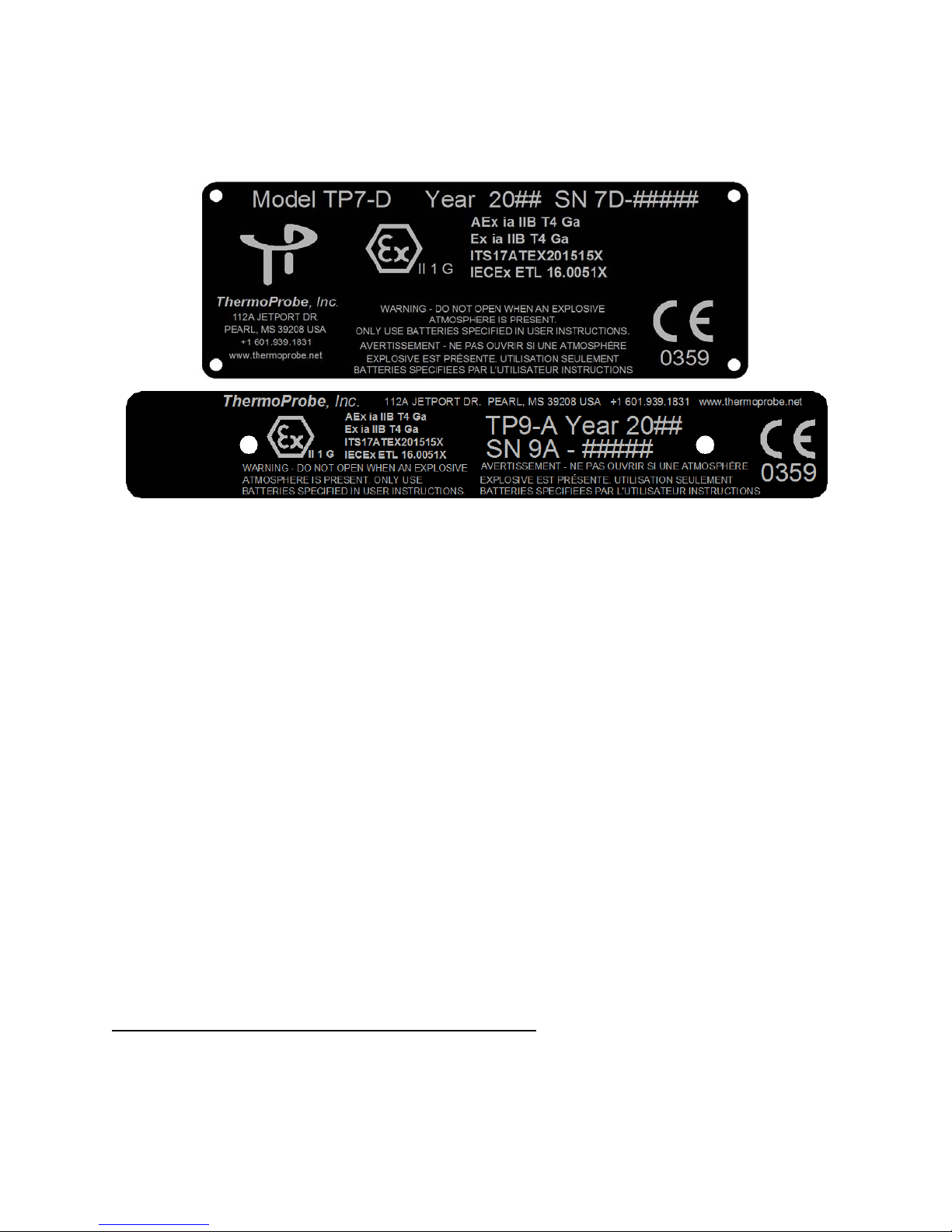
Thermoprobe Models TP7D and TP9A
English | Sp
ANUAL
TP7-D
TP9-A
SER
U
M
anish | French | Russian | Chinese
Page 2
EUDeclarationofConformityaccordingtodirective2014/34/EU(ATEX)
Thermoprobe,Inc.herebydeclarestheTP7‐DandTP9‐Aproductstobeinaccordancewiththefollowingstandards
anddirectives:
Nameandad
DescriptionofDevices
dressofManufacturer ThermoProbe,Inc.
112AJetportDr.
Pearl,MS39208USA
TP7‐DandTP9‐A
PortableElectronicThermometers
Ex-Designation
EC‐TypeExaminationCertificate
NotifiedBod
Auditingbod
AppliedHarmo
EN60079‐0:2012+A112013 Explosiveatmospheres–Part0:Equipment–Generalrequirements
EN60079‐11:2012 ExplosiveAtmospheres–Part11:EquipmentProtectionbyIntrinsic
AppliedEuropeanDire
2014/34/EU‐Equipmentandprotectivesystemsintendedforuseinpotentiallyexplosiveatmospheres
ThermoProbe,Inc.
LukeBartkiewicz
President
II 1 G Ex ia IIB T4 Ga
yIntertekTesting&CertificationLimited
y(QAN) IntertekTesting&CertificationLimited
nizedStandards
ctives
ITS17ATEX201515X
IntertekHouse
CleeveRoad
Leatherhead,
SurreyKT227SB,UK
IntertekHouse
CleeveRoad
Leatherhead,
SurreyKT227SB,UK
IdentificationNumber:0359
Safety‘i’
10/10/2017,JK
Page 3
USER INSTRUCTIONS - TP7-D & TP9-A
INTRODUCTION
This manual describes the basic function, use and safety instructions for a model TP7-D and TP9-A portable di gital
thermometer instrument.
REPLACING BATTERY
When the battery voltage is low, the low battery icon will show on the display.
When the battery voltage is very low, the backlight will no longer operate and the low battery icon will ‘blink’ on the
display.
Replace batteries as soon as possible in a safe location after the low battery is noticed. This will ensure backlight
operation, and avoid possible malfuncti oni ng. Do not at t em pt t o cal i brat e the i nst rument if the low battery indicator is
displayed.
WARNING:
Batteries must be changed in Non-hazardous area.
Batteries must be of correct approved type.
Batteries must be installed with correct polarity making sure the (+) end of the battery is aligned with (+)
symbol embossed in the b attery c ase.
Batteries must not be installed with polarity reversed where one cell could charge another cell.
New batteries must not be mixed with old batteries. Batteries must not be mixed with batteries of other
models or manufacturers.
a) Ensure the instrument is in a non-hazardous area & powered off.
b) Use a #2 Phillips drive to remove the 3 screws holding the front cover on the TP7-D or the 2 screws holding the
front cover on the TP9-A.
c) Use a #1 Phillips drive to remove the single screw from the battery cover. Remove the battery cover, push one
battery towards the spring contact and lift battery up from the holder, and then remove the r e maining bat tery.
d) Install each new battery making sure the (+) end of the battery is aligned with (+) symbol embossed in the battery
case.
e) Replace the retaining device and reinstall the cover.
CERTIFIED Batteries for the TP9-A and TP7-D are as follows:
Manufacturer Type Part Number
Duracell AA (LR6) Alkaline MN1500
Panasonic AA (LR6) Alkaline LR6XWA
GP (Gold Peak) AA (LR6) Alkaline GP15A
AUTHORIZED REPAIR
It is recommended that service beyond the scope of this m anual be performed by ThermoProbe, Inc. or one of its
authorized distributors.
See www.thermoprobe.net for video on proper use of this instrument. Refer to Am erican Pet roleum Institut e
measurement standard Chapter 7.2.
10/2017, JK
Page 4
g
r
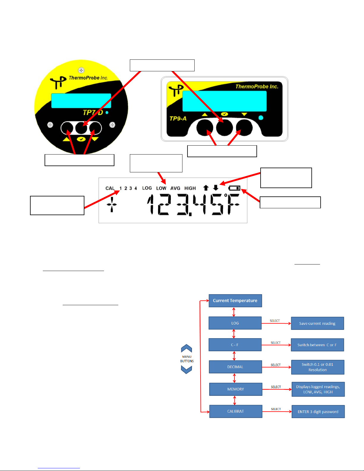
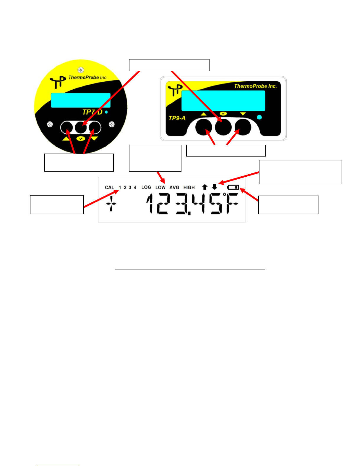
USER INTERFACE
Power/Select Button
Up/Down Menu Buttons Icons for Memory
readin
s
Up/Down Menu Buttons
Temperature
indicating arrows
Indicators for
calibration points
Low battery indicato
Power Button:
Pressin
g the Power button once will turn on the device. (Note: The instrument will automatically power off 20 mi n ut e s
after the last button push.) Pressing and holding the “Power” button until it displays ‘OFF’ will turn off the instrument.
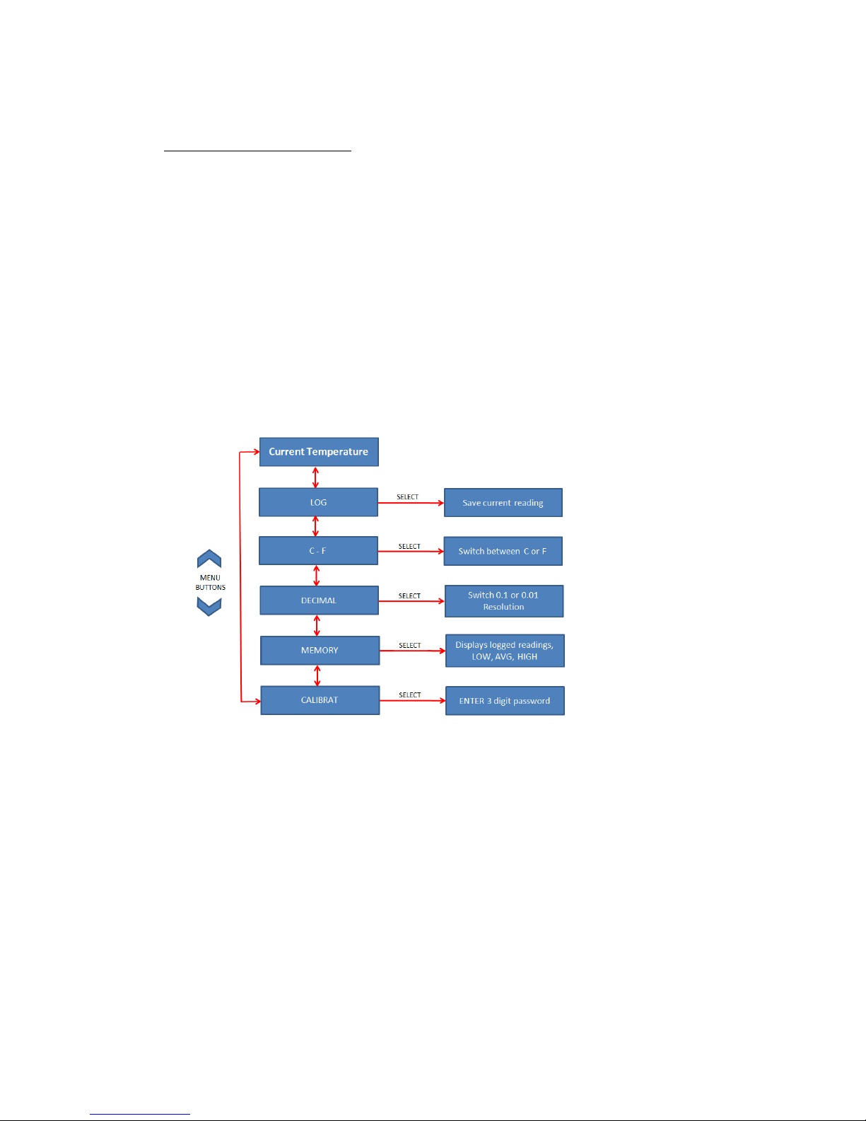
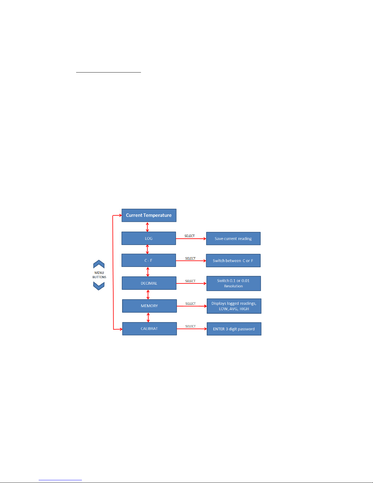
Selection MENU:
Use the “Up/Down” Menu buttons
Saves current stable temperature up to 4 readings
LOG:
C-F: Select Celsius or Fahrenheit temperature display
DECIMAL: Select 0.1 or 0.01 display resolution
MEMORY - Use “up/down” buttons to display:
Lowest reading
Average reading
Highest reading
Saved (Logged) readings 1-10
(Use CLR LOG to erase saved readings)
CALIBRAT: Enter calibration/adjustment mode
(Requires 3 digit password: 112) - See Calibration Procedure
for the following selections:
10/2017, JK
Page 5

Backlight
When the instrument is operating in low-light conditions a photocell will detect this situation and turn the backlight
on.
Temperature Logging
It is necessary for the temperature to be stable before logging temperature. The display arrows will flash 3 times when
the temperature reading has stabilized.
If you wish to log the temperature, Press the “down” button once until LOG is displayed. Press the “Select” button
once to save a reading. An acknowle dgment of a sa ved reading will occur with a display of “LOG 1-10”. This can be
repeated for up to 10 saved readings.
The logged temperatures can be accessed from the MEMORY menu. Logged temperatures will display with the LOG
icon and a prefix (1,2,3,4,5,6,7,8,9,0) corresponding to the previously logged readings. The up/down b uttons can be
used to advance through the readings. Select EXIT to return to the temperature display.
Logged readings will be retained even after the unit is powered off. Logged readings can be cleared by going to the
Memory section of the Menu and selecting CLR LOG. New readings cannot be taken until the readings are cleared.
USB Memory
A micro-usb connection is available on the circuit board allowing access to calibration & logged data.
Warning: Do not access the circuit board in a hazardous location.
Lowest, Highest & Average readings
The lowest, highest and average readings can be accessed through the MEMORY menu. The readings are indicated
by the LOW, AVG or HIGH icons on the display. These readi ngs are not related to the logged readings, but are
determined from the temperature when the unit is powered on. These readings are deleted after the unit is powered
off.
Display Codes
OPEN CKT - Indicates the sensor is operating above its tem perature l imit, the Probe Assembly is open circuited
from a cut or broken section, or the cable is not properly inserted at the circuit board t ermi nal. The most common cause
is a damaged cable.
SHORT CKT - Indicates the sensor is operating below its temperature limit or the Probe Assem bly is short circuite d
due to a smashed or cut section. The most common cause is a damaged cable.
NONE – There are no logged readings saved in memory.
2 WIRE – A 2 wire probe connection has been detected.
3 WIRE – A 3 wire probe connection has been detected.
NO CAL – The device does not have stored calibration data for the temperature probe. Perform an
adjustment/calibration before use.
10/2017, JK
Page 6
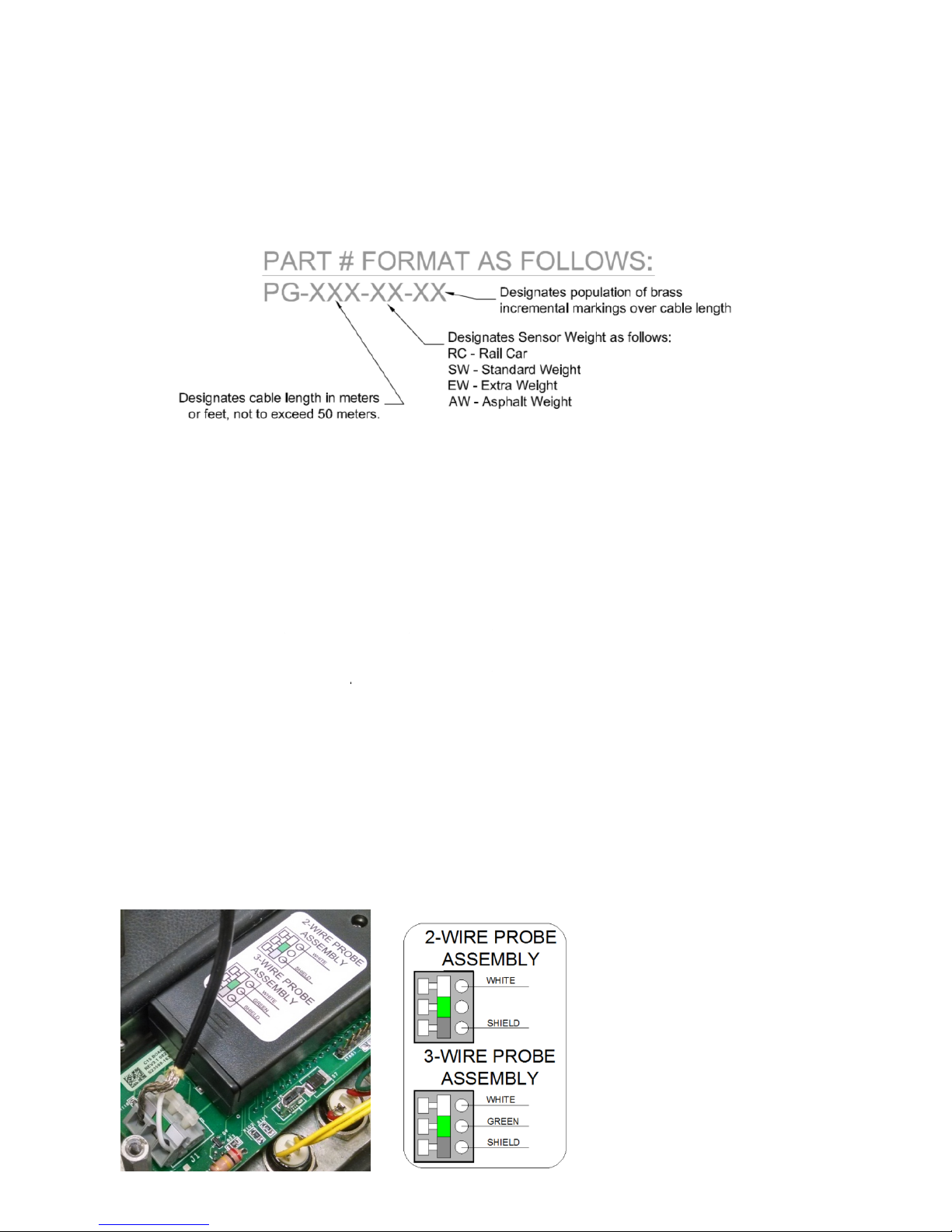
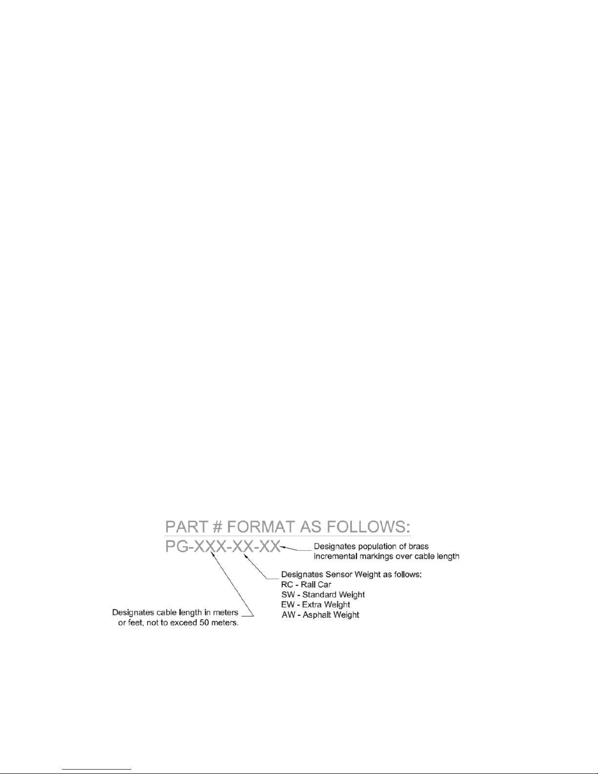
Probe Types
The TP7-D or TP9-A can use either 2-wire or 3-wire probe assemblies.
ThermoProbe replacement probe assemblies are availa bl e i n different configurations. The cable length is available in
lengths up to 50 meters or 165 feet. Standard brass marki ngs are available applied in 5 fe et or 1 meter increments. The
sensors are available with 4 weight types. The probe assembly part confi gur at i ons are as fo l l ows:
REPLACING THE PROBE ASSEMBLY
NOTES:
1) Replacement of the probe assembly requires re-calibration of the device. Replacement should only be
done by experienced personnel and if calibration equipment is available.
2) Please refer to IEC/EN 60079-19 (Explosive atmospheres - Part 19: Equipment repair, overhaul and
reclamation) when making the repair.
3) Only use replacement probe assemblies obtained from ThermoProbe, Inc. or one of its authorized
distributors.
a) First fo
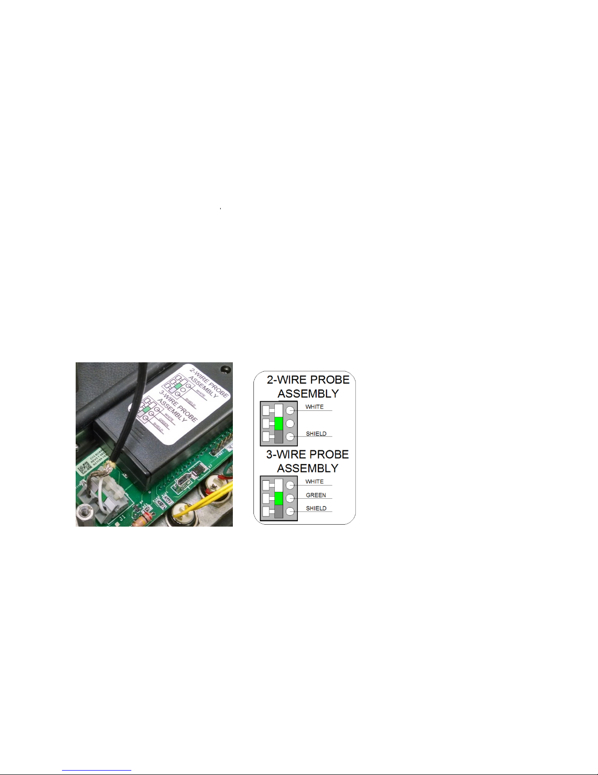
b) On the circuit board push the terminals clamps down and remove the wires noting the wire lead color code
arrangement. See Figure 1.
c) Set the cover and circuit board aside and remove the strain relief knot in cable assembly.
d) Unwrap the cable from the assembly and pull the cable free of the rubber grommet.
e) Insert the new cable wire through the rubber grommet and then pull several inches of cable past the grommet.
f) Tie a simple overhand knot in the cable at the grommet for strain relief and pull the knot up to the grommet.
g) On the circuit board, push the terminal clamp levers down and insert the new wire leads according to the terminal
color codes. The label indicates how to connect a 2 wire probe vs. a 3 wire probe (includes green wire). See Figure 1.
h) Reinstall the batteries and cover and re-spool the cable assembly.
i) Perform a calibration (see calibration procedure).
Figure 1: Probe Assembly Lead Attachment
llow REPLACING BATTERY instructions a through c to remove batteries.
White – positive sensor wire
Green –
Silver – negative sensor wire & shield wire
cable compensating wire (not used on 2 wire models)
10/2017, JK
Page 7
CALIBRATION PROCEDURE
The calibration mode should only be accessed by qualified personnel with proper equipment; otherwise
calibration integrity may be compromised. Read the following instructions carefully.
At least 2 points are required to make an adjustment. (2-Point calibration). Additional points can be taken
(3-Point or 4-Point calibration) to calibrate a large range of temperatures (e.g. 0°F to 300°F) or if you want
to match specific points in your range. You should include points at the bottom and top of the range. You
must have the proper equipment for every point of calibration.
Do not attempt to calibrate the instrument if the low battery indicator has been displayed since the new
calibration values may not be properly s tored to memory.
Refer to API 7.2 or another recognized standard for routine calibration verification recommendations.
Calibration must not be performed in any environment considered to be hazardous.
Equipment needed:
Ice Bath or other low temperature bath with reference thermometer.
Warm to hot fluid bath between 20°C (approx 68°F), or higher up to 90°C (approx 194°F) with reference
thermometer. (see Note)*
Optional high temperature oil bath at about 150°C/300°F and reference thermometer.
*Note for limited calibration: If entire range capability of instrument is not required, the 2 point high adjustment
can be made at a temperature relatively close to the common temperature of the liquid measured and accuracy
will be maintained within the limited range. For example: If liquid product to be measured is commonly less than
38°C (approx. 100°F), then a “high point” calib ra t io n c a n be made near that temperature. Temperature accuracy
above this calibration point cannot be assured.
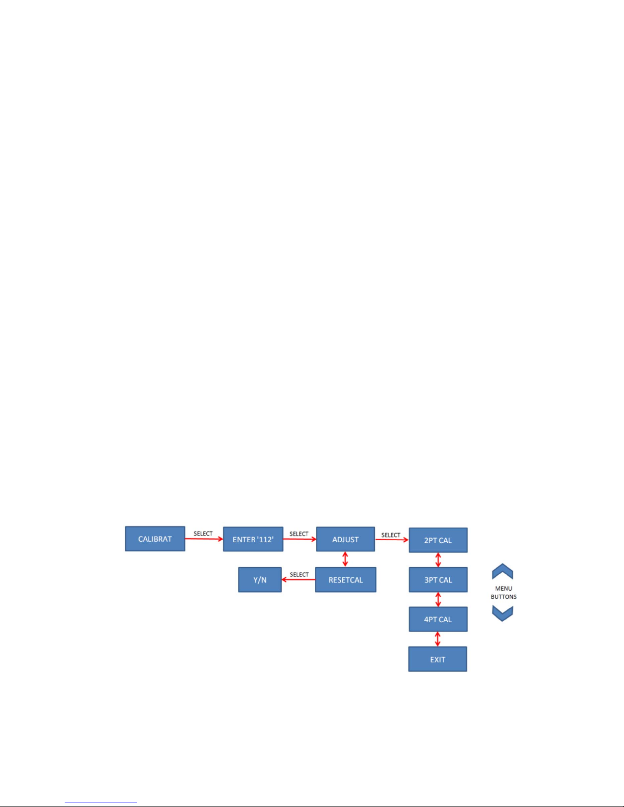
To calibrate proceed with the following steps:
1. Enter calibration mode by going to CALIBRAT in the selection Menu. When this is selected, the user will be
prompted to enter a 3 digit password. Using the “up/down” buttons allows each digit to be adjusted. Once the
correct value is set, advance to the next digit by pressing the “select” button. After the 3
“select” button to enter Calibration mode. If an incorrect password is entered, FAIL will display and the unit
will return to temperature mode. Once in Calibration mode the ‘CAL’ icon on the display will blink. The
calibration mode password is: 112
2. Select ADJUS
2PT CAL, 3PT CAL or 4PT CAL using the select button.
T from the calibration menu and then select the desired number of calibration points. Pick
NOTE: If the user is not ready to enter the calibration mode, the EXIT option can be chosen.
rd
digit is set press the
10/2017, JK
Page 8

3. T
he device is now in adj ustm en t m ode . The di spl ay will show ADD PT1. The “up/down” buttons can be used
to select a different point to adjust or CANCEL. If the CANCEL option is chosen then the calibration
procedure is exited and the prior calibration values are re-activated.
ADD PT1 = Lowest temperature point
ADD PT2 = the next higher temperature point
ADD PT3 = the next higher temperature point (only used in 3-point calibrati on or 4-point calibrati on mode)
ADD PT4 = the highest temperature point (only used in 4-point calibrati on mode)
ADJ DONE = Save and exit calibration mode (all points adjusted & valid)
CANCEL = Exit calibration mode without saving
Pick which point to adjust and press the select button to begin. The current temperature will display and the
CAL icon and the number of the point to adjust will now be blinki ng.
NOTES:
o Calibration can be performed to hundredths of a degree.
o The up/down buttons can be used to increase or decrease the display reading.
o Holding the up/down buttons adjusts 0.1 degrees increments.
o Momentary Presses of the up/down buttons for less than 0.5 seconds adjusts 0.01 degrees for every
press.
o The display arrows will flash 3 times when the temperature reading has stabilized.
o All points must be saved before selecting ADJ DONE. A DATA ERR message will display if all
points have not been saved or are not in increasing temperatures. (Ex: PT1 = 32F, PT2 = 120F, PT3
= 250F)
o While in calibration mode the temperature will display based on the prior calibration curve.
o The RESETCAL feature can be used to return the unit to a factory calibration curve.
(calibration/adjustment will still be required ).
o The RESETCAL (reset to factory calibration) feature should be used i f th e pro be is repl a ced usi ng
a 2-wire assembly instead of a 3-wire assembly or if prior calibration has caused the unit to read
excessively out of tolerance.
4. Once the temperature has stabilized, using a reference device check the actual temperature in the bath and use
the “up/down” buttons to adjust the device to the a ctual temperature. Once the device temperature matches the
actual temperature, press the select button to save the set ti ng. The display will show SAVE or EXIT. If
EXIT is selected it will return to the ADD PT1 menu. Once SAVE is
selected the display will advance to the
next temperature point for adjustment showing ADD PT…. The up/down buttons can be used to select a
different point to adjust or CANCEL. If the CANCEL option is chosen then the calibration procedure is exited
and the prior calibration values are re-activated.
o NOTE: Once SAVE is selected the temperature display will return to the previous reading until the
calibration is completed.
o NOTE: If SAVE is selected before the temperature has stabilized, the display will show NOT
STABLE. Wait for the temperature to stabilize before saving.
5. Move the probe to the next bath and repeat step 4. After you save the highest temperature point the display
will flash READY and the new calibration settings will be in effect. The buttons will now resume their
normal operating functions. The calibration setti ngs are saved to flash memory when the device is turned off.
The unit will not turn off automatically. Manually turning the unit off saves the calibration data.
ThermoProbe, Inc.
112A JETPORT DR.
PEARL, MS 39208
Tel: +1 601.939.1831
Fax: +1 601.355.1831
sales@thermoprobe.net
www.thermoprobe.net
10/2017, JK
Page 9

SAFETY INSTRUCTIONS - TP7-D & TP9-A REV 102017
These ThermoProbe instruments are intended for use in both hazardous (potentially flammable or explosive) and nonhazardous areas under dry conditions at ambient temperatures between -20 to 40°C.
The instruments are not intended for use in permanent outdoor installations and are not intended or tested for i cing
conditions.
stresses (e.g. vibration, heat, impact, etc.).
requirements.
a) The user must have a thorough knowledge of the products to be measured and must know of the safety precautions
to be taken when working with the material to be measured.
b) The instrument shall be checked concerning severe defects; check that instrument is com plete (i ncl uding
grounding/bonding cable), has good batteries, etc. If necessary, check measurement accuracy. If any defects are
found, the instrument should not be used until repairs have b een made.
c) The instrument, especially cable and probe, should be clean for safety and ease of use.
d) The physical measurement location should be evaluated for primary and secondary risks.
e) Power source must be removed before performing any maint enance.
f) Exchange of components other than the batte ri es may compromise ATEX/IECEx or other certifications and shall
only be undertaken by ThermoProbe or one of its qualified service providers. See also “Authorized Repair” section.
g) To reduce the risk of fire or explosion, this device must be bonded to the vessel according to clause 6.3.2 e),
IEC/EN 60079-14 before and during introduction into the vessel and shall remain bonded until the sensor probe is
completely withdrawn from the vessel.
h) The device must remain bonded to ground/earth using the provided connection whenever a hazardous atm osphere
could be present as well as d uri n g s i t uat i o ns wh ere electrostatic charging can occur such as the
the thermometer cable or filling or emptying of the tank.
CAUTION: In the event that any part of the instrument should become electrostatically charged in a potentially
hazardous location, follow company policies for testing and clearing the area of any hazardous gases before
attempting to bond the instrument to earth ground. If this is not possible allow sufficient time for the instrument to
naturally dissipate any charges before attempting to bond to earth ground. Given the atmosphere, this could take
several hours.
Additional means of protection should be used where the equipment may be exposed to excessive external
The user must have a working knowledge of appropriate safety
unwinding/winding of
GUIDANCE NOTE
Problems with aggressive substances and environments: Be aware of aggressive substances and that ext ra protection
may be needed.
Caustic soda, highly basic and acidic substances will erode aluminum and copper ground clip and wire. The Sensor-
Cable assembly has external surfaces of stainless steel and fluoropolymer material. Exposure to Excessive heat can
melt the plastic components of the instrument.
10/2017, JK
Page 10
SAFETY APPROVALS FOR TP7-D AND TP9-A:
AEx ia IIB T4 Ga
Applicable Standards are: Agency or Safety Designation
IEC 60079-0:Ed 6, IEC 60079-11:Ed 6 IECEx
EN 60079-0:2012 + A11 3013, EN60079-11:2012 Europe: ATEX
INTRINSIC SAFETY
Intrinsically safe equipment is defined as "equipment and wiring which is incapable of releasing sufficient electrical
or thermal energy under normal or abnormal conditions to cause ignition of a specific hazardous atmospheric mixture
in its most easily ignited concentration." (ISA-R P1 2.6 ) This is achieved by limiting the amount of powe r avai l a bl e t o
the electrical equipment in the hazardous area to a level below that whi ch will ignit e the gas es.
In order to have a fire or explosion, fuel, oxygen and a source of ignition must be present. An intrinsically safe system
assumes the fuel and oxygen is present in the atmosphere, but the system is designed so the electrical energy or
thermal energy of a particular instrument loop can never be great enough to cause ignition.
BATTERIES
WARNING:
Batteries must be changed in Non-hazardous area.
Batteries must be of correct approved type.
Batteries must be installed with correct polarity making sure the (+) end of the battery is aligned with (+)
symbol embossed in the b attery c ase.
New batteries must not be mixed with old batteries.
Batteries must not be mixed with batteries of other models or manufacturers.
Batteries must not be installed with polarity reversed where one cell could charge another cell.
CERTIFIED Batteries for the TP9-A and TP7-D are as follows:
Manufacturer Type Part Number
Duracell AA (LR6) Alkaline MN1500
Panasonic AA (LR6) Alkaline LR6XWA
GP (Gold Peak) AA (LR6) Alkaline GP15A
10/2017, JK
Page 11

INSTRUCCIONES PARA EL USUARIO - TP7-D Y TP9-A
INTRODUCCIÓN
Este manual describe las instrucciones básicas de funcionamiento, uso y seguridad, para los modelos de instrumento
de termómetro digital portátil TP7-D y TP9-A.
CAMBIO DE LA BATERÍA
Cuando la batería está baja, en la pantalla aparece el ícono de batería baja.
Cuando la batería está muybaja, la retroiluminación ya no funciona y el ícono de batería baja "parpadea" en la
pantalla.
Al reconocer que la carga de las baterías está baja, cámbielas tan pronto como sea posible y en un lugar seguro. Esto
garantiza el funcionamiento de la retroiluminación y evita el posible mal funcionamiento. No intente calibrar el
instrumento si el indicador de batería baja está encendido.
ADVERTENCIA:
Se deben cambiar las baterías en un área sin riesgos.
Las baterías deben ser del tipo aprobado correcto.
Se deben instalar las baterías con la polaridad correcta, asegurándose de que el lado (+) de la batería esté
alineado con el símbolo (+) realzado en el espacio de la batería.
No se deben instalar las baterías con la polaridad invertida, donde una celda podría cargar otra celda
equivocada.
No se deben mezclar baterías nuevas con baterías viejas. No se deben mezclar las baterías de diferentes
modelos o fabricantes.
a) Asegúrese de que el instrumento esté en un área no peligrosa y que esté apagado.
b) Utilice un desatornillador Phillips n.º 2 para retirar los 3 tornillos que sostienen la tapa delantera en el TP7-D o
los 2 tornillos que sostienen la tapa delantera en el TP9-A.
c) Utilice un desatornillador Phillips n.º 1 para retirar el tornillo de la cubierta de la batería. Retire la cubierta de la
batería, empuje una batería hacia el contacto de resorte y saque la batería del espacio, luego retire la batería restante.
d) Instale cada batería nueva asegurándose de que el lado (+) de la batería esté alineado con el símbolo (+) realzado
en el espacio de la batería.
e) Vuelva a colocar el dispositivo de retención y reinstale la cubierta.
Las baterías CERTIFICADAS para el TP9-A y para el TP7-D son las siguientes:
Fabricante Tipo Número de parte
Duracell AA (LR6) Alcalina MN1500
Panasonic AA (LR6) Alcalina LR6XWA
GP (Gold Peak) AA (LR6) Alcalina GP15A
REPARACIÓN AUTORIZADA
Se recomienda que el mantenimiento que no esté incluido en el ámbito de este manual sea llevado a cabo por
ThermoProbe, Inc. o por uno de sus distribuido res aut o ri zad os.
10/2017, JK
Page 12

Vea en www.thermoprobe.net un video sobre el uso adecuado de este instrumento. Consulte el Capítulo 7.2 de la
norma de medición del Instituto Americano del Petróleo (American Petroleum Institute).
INTERFAZ DEL USUARIO
Botón de Encendido/Selección
Botones Arriba/Abajo Íconos para lecturas
de memoria
Botones Arriba/Abajo
Flechas
indicadoras de
temperatura
Indicadores de
puntos de
calibración
Indicador de batería
Botón de encendido:
Al
presionar una vez el botón de Encendido se enciende el dispositivo. (Nota: El in strumento se apaga
automáticamente 20 minutos después de la última presión en el botón).
hasta que la unidad muestra "OFF", se apaga el instrumento.
Al presionar y sostener el botón “Power”
10/2017, JK
Page 13
MENÚ de selección:
Utilice los botones de menú “Arriba/Abajo”
LOG: Guarda la temperatura estable actual por hasta 4 lecturas.
C-F: Selecciona grados Celsius o Fahrenheit para la temperatura que aparecerá en pantalla.
DECIMAL: Selecciona la resolución de 0.1 o 0.01 para la pantalla.
MEMORY - Utilice los botones “Arriba/Abajo” para mostrar:
Lectura más baja
Lectura promedio
Lectura más alta
Lecturas guardadas (Logged) 1-10
(Use CLR LOG para eliminar las lecturas guardadas)
CALIBRAT: Ingresa al modo de calibración/ajuste
(Requiere una contraseña de 3 dígitos: 112) - Cons ul t ar el Proce di mie nto de calibración
para las siguientes selecciones:
Retroiluminación
Cuando el instrumento opera en condiciones de baja iluminación, una fotocelda detecta la situación y enciende la
retroiluminación.
Registro de temperatura
Es necesario que la temperatura esté estable antes de registrarla. La flechas de la pantalla parpadean 3 veces cuando
la lectura de la temperatura se estabiliza.
Si desea registrar la temperatura, presione el botón “down” hasta que aparezca LOG. Presione el botón “Select”
una vez para guardar una lectura. Se presenta una confirmación de la lectura guardada mostrando “LOG 1-10”. Se
puede repetir esto para guardar hasta 10 lecturas.
Se puede acceder a las temperaturas guardadas desde el menú MEMORY. Las temperaturas guardadas se muestran
con el ícono LOG y un prefijo (1, 2, 3, 4, 5, 6, 7, 8, 9, 0) correspondiente a las lecturas guardadas previamente. Se
pueden usar los botones arriba/abajo para desplazarse entre las lecturas. Seleccione EXIT para regresar a la pantalla
de temperatura.
10/2017, JK
Page 14
ecturas guardadas se conservan incluso después de apagar la unidad. Se pueden eliminar las lecturas guardadas
Las l
al ingresar a la sección Memory y seleccionar CLR LOG. No se pueden tomar nuevas lecturas hasta que se
eliminan las lecturas.
Memoria USB
Hay una conexión micro-USB disponible en la tarjeta del circuito que permite acceder a la calibración y los datos
guardados.
Advertencia: No acceda a la tarjeta del circuito en un área peligrosa.
Lecturas mínima, máxima y promedio
Se puede acceder a las lecturas mínima, máxima y promedio a través del menú MEMORY. Las lecturas tienen una
indicación de ícono LOW (mínima), AVG (promedio) o HIGH (máxima) en la pantalla. Estas lecturas no están
relacionadas con las lecturas guardadas, se determinan a partir de la temperatura cuando se enciende la unidad.
Dichas lecturas se borran cuando se apaga la unidad.
Códigos de pantalla
OPEN CKT - Indica que el sensor está funcionando por encima de su límite de temperatura, se abre el circuito del
Ensamble del sensor de una sección cortada o rota o el cable no está insertado adecuadamente en la terminal de la
tarjeta de circuito. La causa más común es un cable dañado.
SHORT CKT - Indica que el sensor está funcionando por debajo de su límite de temperatura o que el Ensamble del
sensor está en cortocircuito debido a una sección rota o cortada. La causa más común es un cable dañado.
NONE – No hay lecturas guardadas en la memoria.
2 WIRE – Se detectó la conexión de una sonda de 2 cables.
3 WIRE – Se detectó la conexión de una sonda de 3 cables.
NO CAL – El dispositivo no tiene datos de calibración almacenados para la sonda de temperatura. Realice un
ajuste/una calibración antes del uso.
Tipos de sonda
El TP7-D o el TP9-A pueden utilizar ensambles de sonda de 2 o de 3 cables.
Los ensambles de sonda de reemplazo ThermoProbe están disponibles en diferentes configuraciones. Hay cables
disponibles en longitudes de hasta 50 met ros o 16 5 pi es. Hay marcas estándar de latón disponibles aplicadas en
incrementos de 5 pies o 1 metro. Los sensores están disponibles en 4 pesos diferentes. Las configuraciones de la
pieza del ensamble de sonda son las siguientes:
10/2017, JK
Page 15
REEMPLAZO DEL ENSAMBLE DE SONDA
NOTAS:
1) El reemplazo del ensamble de sonda requiere de una nueva calibración del dispositivo. El remplazo solo
debe hacerlo personal experimentado y solo si hay equipo de calibración disponible.
2) Consulte IEC/EN 60079-19 (Atmósferas explosivas - Parte 19: Reparación transformación o
recuperación de un equipo) al hacer la reparación.
3) Utilice únicamente ensambles de sonda de reemplazo obtenidos de ThermoProbe, Inc. o de uno de sus
distribuidores autorizados.
a) Siga primero las instrucciones de REEMPLAZO DE BATERÍA a hasta c para retirar las baterías.
b) En la tarjeta del circuito presione las abrazaderas de las terminales hacia abajo y retire los cables teniendo en
cuenta el arreglo por colores de las terminales de los cables conductores. Vea la Figura 1.
Blanco – cable positivo del sensor
Ver
de – cable de compensación (no usado en modelos de 2 cables)
Plateado – cable negativo del sensor y con blindaje
c) Coloque aparte la cubierta y la tarjeta de circuito y deshaga el nudo de alivio de tensión en el ensamble del cable.
d) Desenrolle el cable del ensamble y jale el cable para liberarlo del ojal de hule.
e) Inserte el nuevo cable a través del ojal de hule y luego jálelo varias pulgadas más allá del ojal.
f) Haga un nudo simple en el cable a la altura del ojal como alivio de tensión y jale el nudo contra el ojal.
g) Presione hacia abajo las palancas de las abrazaderas de las terminales e inserte las nuevas terminales de acuerdo
con el código de colores. La etiqueta indica la manera de conectar la sonda de 2 cables o la sonda de 3 cables
(incluye cable verde). Vea la Figura 1.
h) Vuelva a instalar las baterías y la cubierta y enrolle el ensamble del cable.
i) Realice una calibración (consulte el procedimiento de calibración).
Figura 1: Sujeción del cable del ensamble de sonda
PROCEDIMIENTO DE CALIBRACIÓN
Únicamente personal calificado y con el equipo adecuado debe acceder al modo de calibración, de otra
forma puede verse comprometida la integridad de la calibración. Lea cuidadosamente las siguientes
instrucciones.
Se requieren por lo menos 2 puntos para hacer un ajuste. (C al i bració n de 2 pu nt o s ). Se puede n t omar
puntos adicionales (calibración de 3 o 4 punt os) pa ra calib r a r un rang o amplio de temperaturas (p.ej. 0 °F a
300 °F) o si se desea hacer coincidir puntos específicos en el rango. Se deben incluir puntos en la parte
inferior y en la parte superior del rango. Se debe contar con el equipo adecuado para cada punto de
calibración.
No intente calibrar el instrumento si el indicador de batería baja está encendido, ya que los valores de la
nueva calibración pueden no ser guardados adecuadamente en la memoria.
10/2017, JK
Page 16

Cons
No se debe realizar la calibración en un entorno considerado peligroso.
ulte API 7.2 o cualquier otra norma reconocida para obtener recomendaciones sobre la verificación
rutinaria de calibración.
Equipo necesario:
Baño de hielo u otro baño de baja temperatura con un termómetro de referencia.
Baño de fluido tibio o caliente entre 20 °C (aprox. 68 °F), o más, hasta 90 °C (aprox. 194 °F) con
termómetro de referencia (ver la Nota)*.
Baño opcional de aceite a alta temperatura a aproximadamente 150 °C/300 °F y termómetro de referencia.
*Nota para calibración limitada: Si no se requiere toda la capacidad del rango del instrumento, se puede realizar
el ajuste de 2 puntos altos a una temperatura relativamente cercana a la temperatura común del líquido medido y
la precisión se mantendrá dentro del rango limitado. Por ejemplo: Si el producto líquido a medir está , por lo
general, a menos de 38 °C (aprox. 100 °F), entonces se puede hacer una calibración de “punto alto” en el
entorno de esa temperatura. No se puede asegurar la precisión de la temperatura por encima de este punto de
calibración.
Siga los pasos siguientes para la calibración:
1. Ingrese al modo de calibración en CALIBRAT, en el Menú de selección. Cuando se selecciona esto, se le
pide al usuario que ingrese una contraseña de 3 dígitos. El uso de los botones “arriba/abajo” permite ajustar
cada dígito. Una vez establecido el valor correcto, avance al siguiente dígito presionando el botón “select”.
Después de ingresar el 3
ingresa una contraseña incorrecta, se muestra FAIL y la unidad vuelve al modo de temperatura. Una vez en
el modo de Calibración, parpadea el ícono "CAL" en la pantalla. La contraseña para el modo de
calibración es: 112
2. Seleccione
calibración. Seleccione 2PT CAL, 3PT CAL o 4PT CAL utilizando el botón de selección.
EXIT (Salir).
3. El dispositivo está ahora en el modo de ajuste. La pantalla muestra ADD PT1. Se pueden usar los botones
“arriba/abajo” para seleccionar un punto de ajuste diferente o CANCEL. Si se elige la opción CANCEL,
entonces se sale el procedimiento de calibración y se vuelven a activar los valores anteriores de calibración.
ADD PT1 = punto de temperatura mínima
ADD PT2 = el siguiente punto de temperatura más alta
ADJUST en el menú de calibración y luego seleccione la cantidad deseada de puntos de
NOTA: Si el usuario no está listo para ingresar al modo de calibración, se puede elegir la opción
er
dígito, presione el botón “select” para ingresar al modo de Calibración. Si se
10/2017, JK
Page 17

D PT3 = el siguiente punto de temperatura más alta (se usa únicamente en el modo de calibración de 3
AD
o 4 puntos)
ADD PT4 = el punto de temperatura más alta (se usa únicamente en el modo de calibración de 4 puntos)
ADJ DONE = Guardar y salir del modo de calibración (todos los puntos ajustados y válidos)
CANCEL = Salir del modo de calibración sin guardar
Seleccione el punto a ajustar y presione el botón "select" para iniciar. La temperatura actual se muestra y
parpadean el ícono CAL y el número del punto a ajustar.
NOTAS:
o La calibración se puede llevar a cabo hasta a centésimos de grado.
o Se pueden utilizar los botones arriba/abajo para aumentar o disminuir la lectura de la pantalla.
o Mantener presionados los botones arriba/abajo ajusta en incrementos de 0.1 grados.
o La presión momentánea de los botones arriba/abajo por menos de 0.5 segundos ajusta 0.01
grados para cada presión.
o La flechas de la pantalla parpadean 3 veces cuando la lectura de la temperatura se estabiliza.
o Se deben guardar todos los puntos antes de selecciona r ADJ DONE. Se muestra un mensaje
DATA ERR si no se han guardado todos los puntos o no están en temperaturas crecientes. (P. ej.:
PT1 = 32 °F, PT2 = 120 °F, PT3 = 250 °F)
o Mientras se está en el modo de calibración, se muestra la temperatura con base en la curva anterior
de calibración.
o Se puede usar la función RESETCAL para regresar la unidad a una curva de calibración de
fábrica. (de todos modos será necesaria una calibración o un ajuste).
o Se debe utilizar la función RESETCAL (restablecer la calibración de fábrica) si se cambia la
sonda usando un ensamble de 2 cables en lugar de un ensamble de 3 cables o si la calibración
anterior provoca que la unidad lea excesivamente fuera de la tolerancia.
4. Cuando se estabiliza la temperatura, verificar con un dispositivo de referencia la temperatura actual en el
baño y utilizar los botones “arriba/abajo” para ajustar el dispositivo a la temperatura real. Cuando la
temperatura en el dispositivo coincida con la temperatura real, presione el botón de selección para
guardar la configuración. La pantalla muestra SAVE o EXIT. Si se selecciona EXIT se vuelve al menú
ADD PT1. Cuando se selecciona SAVE la pantalla pasa al siguiente punto de temperatura a ajustar,
mostrando ADD PT…. Se pueden utilizar los botones arriba/abajo para seleccionar un punto difere nte a
ajustar o C
ANCEL. Si se elige la opción CANCEL, entonces se sale el procedimiento de calibración y se
vuelven a activar los valores anteriores de calibración.
o NOTA: Cuando se selecciona SAVE la pantalla de temperatura regresa a la lectura anterior hasta
finalizar la calibración.
o NOTA: Si se selecciona SAVE antes de que se estabilice la temperatura, la pantalla muestra NOT
STABLE. Espere a que se estabilice la temperatura antes de guardar.
5. Pase la sonda al siguiente baño y repita el paso 4. Después de guardar el punto de temperatura más alta, la
pantalla parpadea con el mensaje READY y la nueva calibración entra en efecto. Los botones retoman sus
funciones normales de operación. La calibración se guarda en la memoria flash cuando se apaga el
dispositivo. La unidad no se apaga automáticamente. Se guardan los datos de calibración al apagar
manualmente la unidad.
ThermoProbe, Inc.
112A JETPORT DR.
PEARL, MS 39208
Tel.: +1 601.939.1831
Fax: +1 601.355.1831
sales@thermoprobe.net
www.thermoprobe.net
10/2017, JK
Page 18

INSTRUCCIONES DE SEGURIDAD - TP7-D Y TP9-A
REV. 10/2017
Estos instrumentos ThermoProbe son para su uso tanto en áreas peligrosas (potencialmente inflamables o
explosivas) como no peligrosas, en condiciones secas y a una temperatura ambiente de entre -20 y 40°C.
Los instrumentos no fueron diseñados para usarse en instalaciones permanentes al aire libre y no fueron diseñados ni
sometidos a prueba en condiciones de congelación.
pudiera quedar expuesto a excesivas exigencias externas (p. ej. vibración, calor, impacto, etc.).
conocimiento operativo de los requisitos de seguridad correspondientes.
a) El usuario debe tener un amplio conocimiento de los productos a medir y conocer las precauciones de seguridad a
tomar cuando se trabaja con el material a medir.
b) Se debe revisar el instrumento para detectar defectos graves; controle que el instrumento esté completo
(incluyendo el cable de tierra/unión), que tenga baterías en buenas condiciones, etc. Si fuera necesario, verifique la
precisión de las mediciones. Si se encontrara algún defecto, no se debe utilizar el instrumento hasta que se lleven a
cabo las reparaciones.
c) El instrumento, en especial el cable y la sonda, debe estar limpio por razones de seguridad y de facilidad de uso.
d) Se deben evaluar los riesgos primarios y secundarios de la ubicación física de la medición.
e) Se debe retirar la fuente de energía antes de realizar cualquier operación de mantenimiento.
f) El cambio de componentes que no sean las baterías puede comprometer las certificaciones ATEX/IECEx u otras y
debe llevarlo a cabo ThermoProbe o de uno de sus proveedores de servicio calificados. Consulte también la sección
“Reparación autorizada”.
g) Para reducir el riesgo de incendio o explosión, se debe unir este dispositivo al recipiente conforme a la cláusula
6.3.2 e), IEC/EN 60079-14 antes y durante la introducción al recipiente y debe permanecer unido hasta que la sonda
se retire completamente del recipiente.
h) El dispositivo debe permanecer unido a tierra física utilizando la conexión provista y siempre que pueda haber
presencia de una atmósfera peligrosa, así como en situaciones donde se pueda presentar descarga electrostática,
como alenrollar/desenrollar el cable del termómetro o llenar o vaciar el tanque.
PRECAUCIÓN: En caso de que cualquier parte del instrumento quedara cargada electrostáticamente en una
ubicación potencialmente peligrosa, siga las políticas de la empresa para probar y despejar cualquier gas peligroso
del área antes de intentar unir el instrumento a la tierra física. Si esto no fuera posible, debe dar tiempo suficiente
para que el dispositivo disipe de manera natural cualquier carga antes de unirlo a la tierra física. Según el tipo de
atmósfera, esto puede tardar varias horas.
Se deben utilizar otros medios de protección cuando el equipo
El usuario debe tener
NOTA DE ORIENTACIÓN
Problemas con sustancias y ambientes agresivos: Sea consciente de las sustancias agresivas y de la posible
necesidad de protección adicional.
La soda cáustica, y las sustancias de alto nivel básico o ácido corroen el broche y el cable de aluminio y cobre. El
ensamble de sensor y cable tiene superficies externas de acero inoxidable y un material fluoropolimérico. La
exposición a calor excesivo puede fundir los componentes plásticos del instrumento.
10/2017, JK
Page 19

APROBACIONES DE SEGURIDAD DEL TP7-D Y DEL TP9-A:
AEx ia IIB T4 Ga
Las normas pertinentes son: Agencia o designación de segurid ad
IEC 60079-0:Ed 6, IEC 60079-11:Ed 6 IECEx
EN 60079-0:2012 + A11 3013, EN60079-11:2012 Europa: ATEX
SEGURIDAD INTRÍNSECA
Se define al equipo intrínsecamente seguro como "equipo y cableado que no pueden liberar suficiente energía
térmica o eléctrica, ya sea bajo condiciones normales o anormales, como para provocar la ignición de una mezcla
atmosférica específica peligrosa en su concentración de mayor ignición" (ISA-RP12.6). Esto se logra al limitar la
cantidad de potencia disponible para el equipo eléctrico en el área peligrosa a un nivel inferior al necesario para que
se inflamen los gases.
Para que haya ignición o explosión, debe haber presencia de combustible, oxígeno y una fuente de ignición. Un
sistema intrínsecamente seguro asume que el combustible y el oxígeno están presentes en la atmósfera, pero el
sistema está diseñado de manera tal que la energía eléctrica o la energía térmica del circuito de un instrumento en
particular nunca sean suficientes para provocar la ignición.
BATERÍAS
ADVERTENCIA:
Se deben cambiar las baterías en un área sin riesgos.
Las baterías deben ser del tipo aprobado correcto.
Se deben instalar las baterías con la polaridad correcta, asegurándose de que el lado (+) de la batería esté
alineado con el símbolo (+) realzado en el espacio de la batería.
No se deben mezclar baterías nuevas con baterías viejas.
No se deben mezclar las baterías de diferentes modelos o fabricantes.
No se deben instalar las baterías con la polaridad invertida, donde una celda podría cargar otra celda
equivocada.
Las baterías CERTIFICADAS para el TP9-A y para el TP7-D son las siguientes:
Fabricante Tipo Número de parte
Duracell AA (LR6) Alcalina MN1500
Panasonic AA (LR6) Alcalina LR6XWA
GP (Gold Peak) AA (LR6) Alcalina GP15A
10/2017, JK
Page 20

INSTRUCTIONS D'UTILISATION – TP7-D et TP9-A
INTRODUCTION
Ce manuel décrit le fonctionnement de base et les instructions d’utilisation et de sécurité du thermomètre numérique
portable modèle TP7-D ou TP9-A.
REMPLACER LES PILES
Lorsque la tension des piles est faible, l’icône de pile faible s'affiche sur l’écran.
Lorsque la tension des piles est très faible, le rétroéclairage ne fonctionne plus et l’icône de pile faible « clignote »
sur l’écran.
Remplacez les piles dès que possible dans un endroit sûr après avoir remarqué l’indicateur de pile faible. Cela vous
permettra d’utiliser le rétroéclairage et évitera un éventuel dysfonctionnement. N’essayez pas d’étalonner
l’instrument si l’indicateur de pile faible est affiché.
ATTENTION :
Les piles doivent être changées dans une zone sans risques.
Les piles doivent être du type correct approuvé.
Les piles doivent être mises en place avec la polarité correcte : assurez-vous que l’extrémité (+) de la
batterie est alignée avec le symbole (+) inscrit en relief sur le boîtier de la pile.
Les piles ne doivent pas être mises en place avec une polarité inversée qui ferai t qu ’u ne pi le pourrai t en
charger une autre.
Les nouvelles piles ne doivent pas être mélangées avec d’anciennes piles. Les piles ne doivent pas être
mélangées avec des piles d’autres modèles ou fabricants.
a) Vérifiez que l’instrument se trouve dans une zone sans risques et qu’il est éteint.
b) Utilisez un tournevis cruciforme Phillips numéro 2 pour retirer les 3 vis en maintenant le couvercle supérieur du
TP7-D ou les 2 vis en maintenant le couvercle supérieur du TP9-A.
c) Utilisez un tournevis Phillips numéro 1 pour retirer la vis unique du cache-piles. Retirez le cache-piles, poussez
une pile vers le contact à ressort et soulevez-la hors du compartiment, puis retirez la pile restante.
d) Installez chaque nouvelle pile en faisant en sorte que l’extrémité (+) de la pile soit alignée avec le symbole (+)
inscrit en relief sur le boîtier de la pile.
e) Replacer le cache et remettez en place le couvercle.
Les piles CERTIFIÉES pour le TP9-A et le TP7-D sont les suivantes :
Fabricant Type Référence
Duracell AA (LR6) alcaline MN1500
Panasonic AA (LR6) alcaline LR6XWA
GP (Gold Peak) AA (LR6) alcaline GP15A
RÉPARATIONS AUTORISÉES
Il est recommandé de faire appel à ThermoProbe, Inc. ou à l’un de ses distributeurs autorisés pour toutes les
interventions dépassant le cadre de ce manuel.
10/2017, JK
Page 21

Consultez www.thermoprobe.net pour une vidéo sur l’utilisation adéquate de cet instrument. Référez-vous aux
normes de mesure de l’American Petroleum Institute décrites au chapitre 7.2.
INTERFACE UTILISATEUR
Bouton de marche/sélection
Boutons de menu
Icônes pour les
relevés en
mémoire
Boutons de menu
Flèches d’indication de
température
Indicateurs pour
les points
Indicateur de pile faible
Bouton Marche :
A
ppuyer une fois sur le bouton Marche pour allumer l'appareil. (Note : l’instrument s’éteindra automatiquement au
bout de 20 minutes d'inactivité.)
que le message « OFF » soit affiché.
Pour éteindre l'instrument, appuyer et maintenir le bouton « Marche » jusqu’à ce
10/2017, JK
Page 22

MENU Sélection :
Utilisez les boutons de menu « haut/bas »
LOG : Enregistre jusqu’à 4 relevés de la température actuelle stable
C-F : Sélectionne l’affichage de la température en degrés Celsius ou Fahrenheit
DECIMAL : Sélectionnez une résolution d’affichage de 0,1 ou 0,01
MEMORY – Utilisez les boutons « haut/bas » pour afficher :
le relevé le plu bas
le relevé moyen
le relevé le plus haut
Relevés sauvegardés (« log ») de 1 à 10
(Utilisez CLR LOG pour effacer les relevés enregistrés)
CALIBRAT : Passez en mode étalonnage/réglage
(Nécessite un mot de passe à 3 chiffres : 112 – Voir la pr océdure d'étalonnage
pour effectuer les sélections suivantes :
Rétroéclairage
Lorsque l’instrument fonctionne sous une faible luminosité, une cellule photoélectrique le détecte et active le
rétroéclairage.
Enregistrement des températures
La température doit être stable pour permettre l’enregistrement. Les flèches de l’affichage clignoteront 3 fois pour
indiquer que la température relevée est stable.
Si vous souhaitez enregistrer la température, appuyez une fois sur le bouton « bas » jusqu’à ce que LOG soit
affiché. Appuyez sur le bouton « Sélectionner » une fois pour enregistrer un relevé. L’enregistrement du relevé sera
confirmé par l’affichage de « LOG 1-10 ». Cette opération peut être répétée pour un maximum de 10 relevés
enregistrés.
10/2017, JK
Page 23

Il est possi
enregistrées seront affichées avec une icône LOG et un préfixe (1, 2, 3, 4, 5, 6, 7, 8, 9, 0) correspondant aux rele vés
enregistrés précédemment. Les boutons haut/bas peuvent être utilisés pour parcourir les enregistrements.
Sélectionnez EXIT pour revenir à l’affichage de la température.
Les relevés enregistrés seront conservés même après l’extinction de l’appareil. Les relevés enregistrés peuvent être
effacés en sélectionnant CLR LOG dans la section Mémoire du menu. Il est impossible de sauvegarder de
nouveaux relevés tant que les anciens ne sont pas effacés.
ble d’accéder aux températures enregistrées depuis le menu MEMORY (Mémoire). Les températures
Mémoire USB
Une connexion micro-USB disponible sur le circuit imprimé permet l’accès à l’étalonnage et aux données
enregistrées.
Attention : N’accédez pas au circuit imprimé dans un endroit dangereux.
Relevés le plus bas, moyen et le plus haut
Le menu MEMORY permet d’accéder aux relevés le plus bas, moyen et le plus haut. Ces relevés sont indiqués par
les icônes LOW, AVG et HIGH sur l'écran. Ces relevés ne sont pas liés aux lectures enregistrés mais sont
déterminés par la température lorsque l’appareil est allumé. Ces relevés sont supprimés après l’extinction de
l’appareil.
Codes d’affichage
OPEN CKT – Indique que le capteur fonctionne au-delà de sa température limite, que l'assemblage de la sonde a
été court-circuité à cause d’une section coupée ou cassée ou que le câble n’est pas inséré correctement dans le
connecteur du circuit imprimé. La cause la plus courante est un câble endommagé.
SHORT CKT – Indique que le capteur fonctionne en dessous de sa température limite ou que l'assemblage de la
sonde est en court-circuit à cause d’une section écrasée ou coupée. La cause la plus courante est un câble
endommagé.
NONE – Aucun relevé n’est enregistré en mémoire.
2 WIRE – Une connexion de sonde à 2 fils a été détectée.
3 WIRE – Une connexion de sonde à 3 fils a été détectée.
NO CAL – L’appareil ne dispose pas de données d’étal on nage stockées pour la sonde de température. Effectuez un
réglage/étalonnage avant utilisation.
10/2017, JK
Page 24

Types de sondes
Les TP7-D ou TP9-A peuvent utiliser des sondes à 2 ou 3 fils.
Des sondes de remplacement ThermoProbe sont disponibles dans différentes configurations. Les câbles sont
disponibles dans des longueurs allant jusqu’à 50 mètres ou 165 pieds. Des marquages en cuivre standards sont
disponibles en incréments de 5 pieds ou d’un mètre. Les capteurs sont disponibles avec 4 types de poids. Les
configurations des pièces d'assemblage de sonde sont présentées comme suit :
REMPLACER LA SONDE
NOTES :
1) Le remplacement de la sonde nécessite un nouvel étalonnage de l’appareil. Le remplacement ne devrait
être effectué que par du personnel expérimenté et que dans le cas où l’équipement d’étalonnage est
disponible.
2) Veuillez vous référer à IEC/EN 60079-19 (Atmosphères explosives - Section 19 : réparation, révision et
remise en état de l’appareil) lorsque vous effectuez la réparation
3) N’utilisez que des assemblages de sonde de remplacement obtenus auprès de ThermoProbe, Inc. ou de
l’un de ses distributeurs autorisés.
a) S
uivez tout d’abord les instructions de REMPLACER LES PILES a à c pour retirer les piles.
b) Sur le circuit imprimé, poussez les griffes du connecteur vers le bas et retirez les fils en notant la disposition des
codes de couleur des fils. Voir Figure 1.
Blanc – fil de capteur positif
Vert
Argent – fil de capteur négatif et fil de blindage
c) Séparez le couvercle et le circuit imprimé et retirez le nœud de décharge de traction de l’assemblage du câble.
d) Déroulez le câble et retirez le passe-câble en caoutchouc.
e) Insérez le nouveau câble dans le passe-câble en caoutchouc et tirez plusieurs centimètres de câble au-delà du
passe-câble.
f) Effectuez un simple nœud plat dans le câble au niveau du passe-câble comme décharge de traction et faites glisser
le nœud jusqu’au passe-câble.
g) Sur le circuit imprimé, poussez les griffes du connecteur vers le bas et insérez les nouveaux fils selon les codes de
couleur du connecteur. L’étiquette indique comment connecter une sonde à 2 et une sonde à 3 fils (celle-ci comporte
un fil vert). Voir Figure 1.
h) Réinstallez les piles et le couvercle et remettez en place l’assemblage du câble.
i) Effectuez un étalonnage (voir la procédure d’étalonnage).
Figure 1 : Connexion des fils de la sonde
– fil de compensation de câble (non utilisé sur les modèles à 2 fils)
10/2017, JK
Page 25

PROCÉDURE D’ÉTALONNAGE
Seul un personnel qualifié disposant d’un équipement approprié devrait avoir accès au mode d’étalonnage.
Dans le cas contraire, l’intégrité de l’étalonnage pourrait être compromise. Lisez les instructions suivantes
avec attention.
Un minimum de 2 points est nécessaire pour effectuer un réglage (ét al o nnage à 2 points). Des points
supplémentaires peuvent être acquis (étalonnage à 3 ou 4 points) pour calibrer une plage de températures
importante (ex. : -15 °C à 150 °C) ou si vous voulez utiliser des points spécifiques de votre plage. Il est
préférable d’inclure des points situés à l’extrémité inférieure et supérieure de la plage. Vous devez disposer
de l’équipement adéquat pour chaque point d’étalonnage.
N’essayez pas de calibrer l’instrument si l’indicateur de pile faible a été affiché. Dans ce cas, les nouvelles
valeurs d’étalonnage pourraient ne pas être stockées correctement en mémoire.
Référez-vous à l’API 7.2 ou à d’autres normes reconnues pour des recommandations de vérification
d’étalonnage de routine.
L’étalonnage ne doit être en aucun cas effectué dans un environnement considéré comme dangereux.
Équipement nécessaire :
Bain de glace ou autre bain à température basse avec un thermomètre de référence.
Bain tiède à chaud entre 20 °C (env. 68 °F) ou plus jusqu’à 90 °C (env. 194 °F) avec un thermomètre de
référence (voir Note)*.
Bain d’huile à haute température optionnel à environ 150 °C/300 °F et thermomètre de référence.
*Note pour un étalonnage limité : Si la plage de fonctionnement complète de l’instrument n’est pas nécessaire,
le réglage du point haut à 2 points peut être effectué à une température relativement proche de la température
habituelle du liquide mesuré et la précision sera conservée à l’intérieur de la plage limitée. Par exemple : Si le
produit liquide à mesurer est habituellement à moins de 38 °C (env. 100 °F), un « point haut » d’étalonnage
peut être établi à un point proche de cette température. La précision de la température au-delà de ce point
d’étalonnage ne peut pas être garantie.
Pour procéder à l’étalonnage, effectuez les étapes suivantes :
1. Entrez en mode étalonnage en allant à CALIBRAT dans le menu de sélection. Une fois ce mode
sélectionné, un mot de passe à 3 chiffres sera demandé à l’utilisateur. Les boutons « haut/bas » permettent
de modifier chaque chiffre. Une fois la valeur correcte définie, p assez au chiffre suivant en appuyant sur le
bouton « sélection ». Une fois le 3
mode d’étalonnage. Si un mot de passe incorrect est entré, FAIL (Échec) sera affiché et l’appareil
reviendra en mode température. Une fois en mode étalonnage, l’icône « CAL » clignotera sur l'écran. Le
mot de passe du mode étalonnage est : 112
e
chiffre défini, appuyez sur le bouton « sélection » pour entrer dans le
10/2017, JK
Page 26

2. Sélectionnez AD
JUST (Régler) dans le menu étalonnage et sélectionnez ensuite le nombre de points
d’étalonnage souhaités. Choisissez 2PT CAL, 3PT CAL ou 4PT CAL à l’aide du bouton de sélection.
NOTE : Si l’utilisateur n’est pas prêt à entrer en mode étalonnage, l’option EXIT (Quitter) peut
être choisie.
3. L’appareil est maintenant en mode réglage. ADD PT1 (Ajouter point 1) sera affiché. Utilisez les boutons
« haut/bas » pour sélectionner un point différent à régler ou CANCEL (Annuler). Si l’option CANCEL est
choisie, la procédure d’étalonnage est interrompue et les valeurs d’étalonnage précédentes sont réactivées.
ADD PT1 = le point de température le plus bas
ADD PT2 = le point de température plus élevé suivant
ADD PT3 = le point de température plus élevé suivant (uniquement utilisé dans les modes d’étalonnage à 3
ou 4 points)
ADD PT4 = le point de température le plus élevé (uniquement utilisé dans le mode d’étalonnage à 4 points)
ADJ DONE = pour enregistrer et quitter le mode étalonnage (tous les points réglés et valides)
CANCEL = quitter le mode d’étalonnage sans enregistrer
Choisissez le point à régler et appuyez sur le bouton de sélection pour commencer. La température actuelle
sera affichée et l’icône CAL et le nombre de points à régler commenceront à clignoter.
NOTES :
o L’étalonnage peut maintenant être effectué au centième de degré.
o Les boutons haut/bas peuvent être utilisés pour augmenter ou diminuer la valeur affichée.
o Maintenir les boutons haut/bas modifie la valeur par incréments de 0,1 degrés.
o Appuyer brièvement sur les boutons haut/bas pendant moins de 0,5 seconde modifie la valeur de
0,01 degré à chaque fois que vous appuyez.
o Les flèches de l’affichage clignoteront 3 fois pour indiquer que la température relevée est stable.
o Tous les points doivent être enregistrés avant de sélectionner ADJ DONE (Réglage terminé). Un
message DATA ERR (Erreur de données) s’affichera si tous les points n’ont pas été enregistrés
ou ne représentent pas des températures croissantes. (Par ex. : PT1 = 0C, PT2 = 50C, PT3 = 120C)
o En mode étalonnage, la température sera affichée en fonction de la courbe d’étalonnage
précédente.
o La fonction RESETCAL (Réinitialiser l’étalonnage) peut être utilisée pour réinitialiser l’appareil
à une courbe d’étalonnage d’usine (l’étalonnage/le réglage devra toujours être effectué).
o La fonction RESETCAL (réinitialiser à l’étalonnage d’usine) devrait être utilisée si la sonde est
remplacée par un ensemble à 2 fils au lieu d’un ensemble à 3 fils ou si l’étalonnage précédent a
provoqué un relevé largement hors tolérance.
4. Un
e fois la température stabilisée, vérifiez la température réelle dans le bain à l’aide d’un appareil de
référence et utilisez les boutons « haut/bas » pour régler l’appareil à la température réelle. Une fois que la
température sur l’appareil correspond à la température réelle, appuyez sur le bouton de sélection pour
enregistrer le paramètre. L’afficheur indiquera SAVE (Enregistrer) ou EXIT (Quitter). Si EXIT est
sélectionné, l’appareil reviendra au menu ADD PT1. Une fois SAVE sélectionné, l’afficheur passera au
prochain point de température en indiquant ADD PT…. Les boutons haut/bas peuvent être utilisés pour
sélectionner un point différent à régler ou choisissez CANCEL (Annuler). Si l’option CANCEL est
choisie, la procédure d’étalonnage est interrompue et les valeurs d’étalonnage précédentes sont réactivées.
o NOTE : Une fois SAVE sélectionné, l’affichage de la température reviendra au relevé précédent
jusqu’à ce que l’étalonnage soit terminé.
o NOTE : Si SAVE est sélectionné avant que la température ne soit stabilisée, l’afficheur indiquera
NOT STABLE (Non stable). Attendez que la température se stabilise avant d’enregistrer.
5. Déplacez la sonde dans le bain suivant et répétez l’étape 4. Après avoir enregistré le point de température le
plus élevé, READY (Prêt) clignotera à l'écran et les nouveaux paramètres d’étalonnage prendront effet. Les
boutons reviendront à leurs fonctions d’exploitation habituelles. Les paramètres d’étalonnage sont
enregistrés dans une mémoire flash lorsque l’appareil est éteint. L’appareil ne s’éteindra pas
automatiquement. Éteindre l’appareil manuellement enregistre les données d’étalonnage.
10/2017, JK
Page 27

INSTRUCTIONS DE SÉCURITÉ - TP7-D ET TP9 - A
RÉV. 102017
Ces instruments ThermoProbe sont destinés à être utilisés dans des zones dangereuses (potentiellement
inflammables ou explosives) et non dangereuses dans des conditions sèches à des températures ambiantes comprises
entre -20 et 40 °C.
Les instruments ne sont pas conçus pour être utilisés dans des installations extérieures permanentes et ne sont pas
conçus ou testés pour des conditions de givrage.
lorsque l’équipement peut être exposé à des contraintes extérieures excessives (par ex. : vibration, chaleur, impact,
L’utilisateur doit disposer d’une connaissance pratique des exigences de sécurité appropriées.
etc.).
a) L’utilisateur doit avoir une connaissance approfondie des produits à mesurer et doit connaître les précautions de
sécurité à adopter lors du travail avec les matériaux à mesurer.
b) Les défauts graves de l’instrument doivent être vérifiés ; vérifiez que l’instrument est complet (y compris le câble
de mise à la terre/masse), que les batteries sont opérationnelles, etc. Si nécessaire, vérifiez la précision des mesures.
Si des défauts sont trouvés, l’instrument ne doit pas être utilisé jusqu’à ce que des réparations aient été effectuées.
c) L’instrument, en particulier le câble et la sonde, doit être propre, pour des raisons de sécurité et de facilité
d’utilisation.
d) Les risques primaires et secondaires de l’endroit de mesure physique devraient être évalués.
e) La source d’alimentation doit être débranchée avant tout entretien.
f) L’échange de composants autres que les piles peut aller à l'encontre des certifications ATEX/IECEx ou d’a ut res
certifications et ne devrait être effectué que par ThermoProbe ou l’un de ses fournisseurs de services qualifié. Voir
également la section « Réparations autorisées ».
g) Pour réduire le risque d’incendie ou d’explosion, cet appareil doit être mis à la masse du réservoir selon les
clauses 6.3.2 e), IEC/EN 60079-14 b avant et durant l’introduction dans le réservoir et doit rester mis à la masse
jusqu’à ce que le capteur de la sonde soit entièrement retiré du réservoir.
h) L’appareil doit rester mis à la masse/terre à l’aide de la connexion fournie chaque fois qu’une atmosphère
dangereuse est potentiellement présente ainsi que dans les situations où une charge électrostatique peut se produire,
le déroulement/l’enroulement du câble du thermomètre ou le vidage ou le remplissage du réservoir.
comme
ATTENTION : Dans le cas où une partie quelconque de l’instrument deviendrait chargée électrostatiquement dans
un endroit potentiellement dangereux, suivez les directives de l’entreprise pour tester la présence de gaz dangereux
et les éliminer avant d’essayer de mettre l’instrument à la terre. Si cela s’avère impossible, attendez suffisamment
longtemps pour que l’instrument dissipe toute charge avant d’essayer de le mettre à la terre. En fonction de
l’atmosphère, cela pourrait prendre plusieurs heures.
Des moyens supplémentaires de protection devraient être utilisés
CONSEILS
Problèmes avec les substances et les environnements agressifs : soyez conscient des substances agressives et du fait
qu’une protection supplémentaire puisse être nécessaire.
La soude caustique et les substances hautement basiques et acides éroderont le clip et le fil de mise à la terre en
aluminium et en cuivre. L’ensemble capteur-câble comporte des surfaces externes en acier inoxydable et en
fluoropolymère. L’exposition à une chaleur excessive peut faire fondre les parties en plastique de l’instrument.
10/2017, JK
Page 28

APPROBATIONS DE SÉCURITÉ POUR TP7-D ET TP9-A :
AEx ia IIB T4 Ga
Les normes applicables sont : Agence ou désignation de sécurité
IEC 60079-0:Ed 6, IEC 60079-11:Ed 6 IECEx
EN 60079-0:2012 + A11 3013, EN60079-11 : 2012 Europe : ATEX
SÉCURITÉ INTRINSÈQUE
Un équipement à sécurité intrinsèque est défini comme « un équipement et un câblage incapables de libérer
suffisamment d’énergie électrique ou thermale dans des conditions normales ou anormales pour provoquer
l’inflammation d’un mélange atmosphérique dangereux dans sa concentration la plus facilement inflammable ».
(ISA-RP12.6) Ceci est réalisé en limitant la quantité d’énergie disponible pour l’équipement électrique dans la zone
dangereuse à un niveau inférieur à celui qui enflammera les gaz.
Pour qu’un incendie ou une explosion se produise, un carburant, de l’oxygène et une source d’inflammation doivent
être présents. Un système à sécurité intrinsèque suppose que le carburant et l’oxygène sont présents dans
l’atmosphère, mais le système est conçu de façon à ce que l’énergie électrique ou thermique d’une boucle
d'instrument particulière ne soit jamais suffisante pour provoquer l’inflammation.
PILES
ATTENTION :
Les piles doivent être changées dans une zone sans risques.
Les piles doivent être du type correct approuvé.
Les piles doivent être mises en place avec la polarité correcte : assurez-vous que l’extrémité (+) de la
batterie est alignée avec le symbole (+) inscrit en relief sur le boîtier de la pile.
Les nouvelles piles ne doivent pas être mélangées avec d’anciennes piles.
Les piles ne doivent pas être mélangées avec des piles d’autres modèles ou fabricants.
Les piles ne doivent pas être mises en place avec une polarité inversée qui ferai t qu ’u ne pi le pourrai t en
charger une autre.
Les piles CERTIFIÉES pour le TP9-A et le TP7-D sont les suivantes :
Fabricant Type Référence
Duracell AA (LR6) alcaline MN1500
Panasonic AA (LR6) alcaline LR6XWA
GP (Gold Peak) AA (LR6) alcaline GP15A
10/2017, JK
Page 29
РУКОВОДСТВО ПОЛЬЗОВАТЕЛЯ. МОДЕЛИ TP7-D И TP9-A
ВВЕДЕНИЕ
В настоящем руководстве описаны основные функции цифрового портативного термометра моделей TP7-D
и TP9-A, а также приведены инструкции по его эксплуатации и по технике безопасности при работе с ним.
ЗАМЕНА БАТАРЕЙ
При низком заряде батарей на дисплее отображается соответствующий значок.
О чрезмерно низком заряде свидетельствует отсутствие фоновой подсветки и мигание значка низкого
заряда на дисплее.
После появления значка низкого заряда необходимо как можно скорее заменить батареи в безопасном месте.
Это обеспечит работу фоновой подсветки и позволит избежать возможных неисправностей в работе
прибора. Недопустимо выполнять тарировку прибора, если на дисплее отображается индикатор низкого
заряда.
ПРЕДУПРЕЖДЕНИЕ.
Замена батарей должна производиться в безопасном месте.
Используйте батареи только разрешенного типа.
При установке батарей необходимо соблюдать правильную полярность, то есть полюс батареи,
обозначенный символом «+», должен совпадать с символом «+» на в батарейном отсеке.
Не допускается устанавливать батареи так, чтобы их полярность друг относительна друга была
обратной; при
Недопустимо устанавливать новую батарею вместе со старой. Не допускается одновременное
использование батарей разных моделей или производителей.
a) Прибор должен быть выключенным и находиться в безопасном месте.
b) С помощью крестовой отвертки 2-го размера открутите 3 винта (модель TP7-D) или 2 винта (модель TP9-
A), удерживающие переднюю крышку
c) С помощью крестовой отвертки 1-го размера открутите шуруп, удерживающий крышку батарейного
отсека. Снимите крышку батарейного отсека, переместите одну батарею по направлению к пружинному
контакту и извлеките ее из отсека, после чего извлеките вторую батарею.
d) Установите две новые батареи, при этом полюс каждой батареи, обозначенный символом «+», должен
совпадать с символом
e) Поместите на прежнее место удерживающее устройство и установите крышку на батарейный отсек.
Ниже указаны ОФИЦИАЛЬНО ОДОБРЕННЫЕ батареи для моделей TP9-A и TP7-D.
Производитель Тип Артикул
«Дюраселл» AA (LR6) Щелочная MN1500
«Панасоник» AA (LR6) Щелочная LR6XWA
«Джи-пи» («Голд пик») AA (LR6) Щелочная GP15A
такой схеме одна батарея заряжается от другой.
прибора.
«+» в батарейном отсеке.
РЕМОНТ УПОЛНОМОЧЕННЫМИ ЛИЦАМИ
Все работы по обслуживанию, не описанные в настоящем руководстве, рекомендуется поручать
специалистам компании «Термопроб Инк.» или уполномоченным дистрибьюторам.
На сайте www.thermoprobe.net размещено видео по правильному применению данного прибора. Стандарты
по измерениям описаны в главе 7.2 сборника стандартов Американского института нефти (API).
Октябрь 2017 г., JK
Page 30
р
ИНТЕРФЕЙС ПОЛЬЗОВАТЕЛЯ
Кнопка питания и выбора
Кнопки «вверх» и
«вниз»
Значки для
показаний из
памяти прибора
Кнопки «вверх» и «вниз»
Стрелки для индикации
повышения и понижения
Индикаторы для
точек тарировки
Индикатор низкого
за
яда батарей
Кнопка питания:
При однократном нажатии кнопки питания происходит включение прибора. (Примечание. Прибор
автоматически отключается через 20 минут после последнего нажатия данной кнопки.)
удержании кнопки питания на дисплее отобразится слово «OFF» (выкл.) и прибор выключится.
При нажатии и
Октябрь 2017 г., JK
Page 31
МЕНЮ выбора:
С помощью кнопок «вверх» и «вниз»
LOG (журнал): сохраняет до четырех показаний текущей стабильной температуры.
C-F (Ц — Ф): экран выбора между отображением температуры по Цельсию или по Фаренгейту.
DECIMAL (десятичные разряды): выбор количества разрядов отображаемого значения: с десятыми (0,1)
или с сотыми (0,01) долями.
MEMORY (память) — с помощью кнопок «вверх» и «вниз» можно
С значение температуры.
Среднее значение температуры.
Наибольшее значение температуры.
С 1-го по 10-е сохраненные показания (внесенные в журнал).
(Чтобы удалить сохраненные показания, используйте команду CLR LOG (очистка журнала).)
CALIBRAT (тарировка): вход в режим тарировки (корректировки).
(Требуется пароль из 3 цифр: 112). См. раздел «Порядок тарировки»
можно выбрать следующие элементы:
просмотреть:
Фоновая подсветка
Прибор оснащен фотоэлементом, который включает фоновую подсветку при эксплуатации в условиях
слабого освещения.
Внесение показаний температуры в журнал
В журнал может быть внесено значение только стабильной температуры. После стабилизации показаний
температуры стрелки на дисплее мигнут 3 раза.
Для внесения значения температуры в журнал один раз нажмите кнопку «вниз», чтобы на экране
отобразилось слово LOG (журнал). Чтобы сохранить значение температуры, один раз нажмите кнопку
выбора. Факт сохранения значения подтверждается надписью
помощью данной процедуры можно сохранить до 10 значений температуры.
LOG 1-10 (журнал 1–10) на дисплее. С
Октябрь 2017 г., JK
Page 32

Для доступа к сохраненным в журнале значениям используется меню «MEMORY» (память). Сохраненные
значения температуры отображаются со значком «LOG» (журнал) и цифрой (1, 2, 3, 4, 5, 6, 7, 8, 9 или 0) в
соответствии с порядком сохранения значения в журнале. Для перемещения между сохраненными
значениями используются стрелки «вверх» и «вниз». Для возврата к экрану отображения температуры
нажмите кнопку EXIT (выйти
Значения, внесенные в журнал, сохраняются даже после выключения прибора. Чтобы удалить из журнала
сохраненные значения, перейдите в раздел «Memory» (Память) в меню прибора и выберите команду CLR
LOG (очистка журнала). Новые показания могут быть сняты только после удаления сохраненных значений.
).
USB-накопитель
На плате устройства предусмотрен разъем микро-USB для доступа к данным тарировки и журнала.
Предупреждение. Доступ к плате устройства разрешен только при нахождении в безопасной зоне.
Самое низкое, среднее и самое высокое значения температуры
Для просмотра самого низкого, среднего и самого высокого значений температуры используется меню
«MEMORY» (память). Соответствующие значения отмечаются значками «LOW» (самое низкое), «AVG»
(среднее) и «HIGH» (самое высокое) на дисплее прибора. Данные значения определяются на основании
измеряемой температуры в течение сеанса работы прибора, они не связаны с сохраненными в журнале
значениями. После выключения прибора данные
значения удаляются.
Коды, отображаемые на дисплее
OPEN CKT (разомкнутый контур) — означает, что датчик работает при температуре, превышающей
допустимый верхний предел, что контур узла термощупа разомкнут в результате обрыва или неисправности
участка цепи либо что кабель неправильно подсоединен к клемме монтажной платы. Наиболее
распространенной причиной является повреждение кабеля.
SHORT CKT (короткое замыкание) — означает, что датчик работает при температуре ниже
минимума либо что в контуре узла термощупа произошло короткое замыкание вследствие поломки или
обрыва участка цепи. Наиболее распространенной причиной является повреждение кабеля.
NONE (отсутствует) — означает, что в памяти прибора отсутствуют сохраненные показания температуры.
2 WIRE (двухпроводной) — означает, что подключен двухпроводной термощуп.
3 WIRE (трехпроводной) — означает, что подключен трехпроводной термощуп.
NO CAL (нет данных по тарировке) — означает, что в системе нет сохраненных данных о тарировке
соответствующего термощупа. Перед использованием прибора
необходимо провести его тарировку (корректировку).
допустимого
Октябрь 2017 г., JK
Page 33

Типы термощупов
Для моделей TP7-D и TP9-A могут использоваться как двухпроводные, так и трехпроводные термощупы.
Сменные узлы термощупов «Термопроб» предлагаются в нескольких вариантах конфигурации. Длина их
кабеля может достигать 50 м. Предусмотрена стандартная латунная маркировка, нанесенная через
интервалы, равные 1 м. Датчики предлагаются в четырех вариантах массы. Предусмотрены следующие
конфигурации узла термощупа:
ЗАМЕНА УЗЛА ТЕРМОЩУПА
ПРИМЕЧАНИЯ.
1) После замены узла термощупа необходимо провести повторную тарировку прибора. Замена узла
термощупа должна производиться только опытным персоналом и при наличии тарировочного
оборудования.
2) При производстве работ по ремонту необходимо руководствоваться стандартом IEC/EN 60079-19
( «Взрывоопасные среды. Часть 19. Ремонт, проверка и восстановление электрооборудования)».
3) Допускается использование только сменных узлов термощупа, приобретенных у компании
ThermoProbe, Inc. или у ее уполномоченных дистрибьюторов.
a) Прежде всего, извлеките из устройства элементы питания, выполнив этапы a–c инструкции по ЗАМЕНЕ
БАТАРЕЙ.
b) На монтажной
провода по его расцветке. См. рис. 1.
Белый — положительный провод датчика.
Зеленый — компенсационный провод (отсутствует в двухпроводных моделях).
Серебристый — отрицательный экранированный провод датчика.
c) Убрав крышку и монтажную плату, развяжите узел для снятия натяжения, выполненный в кабельном
узле.
d) Размотайте кабель, удалив его из узла, и вытяните его из резиновой втулки.
e) Вставьте новый провод через резиновую втулку и вытяните несколько сантиметров провода с обратной
стороны втулки.
f) Завяжите простой узел
пока узел не достигнет втулки.
g) На монтажной плате нажмите на рычажки зажима клеммы и вставьте выводы нового провода согласно
расцветке. На ярлыке указывается, как соединять двухпроводной и трехпроводной (с зеленым проводом)
термощупы. См. рис. 1.
h) Поместите батареи на прежнее
i) Проведите тарировку прибора (см. порядок тарировки).
плате нажмите на зажимы клемм и извлеките провода, запомнив местоположение каждого
на кабеле у втулки, предназначенный для снятия натяжения, и протяните кабель,
место, установите крышку и скрутите кабельный узел.
Октябрь 2017 г., JK
Page 34

Рис. 1. Присоединение проводов узла термощупа
ПОРЯДОК ТАРИРОВКИ
Режим тарировки должен использоваться только квалифицированным персоналом с применением
надлежащего оборудования, иначе возможны ошибки тарировки. Внимательно изучите
приведенную ниже инструкцию.
Для осуществления корректировки требуется как минимум 2 точки (двухточечная тарировка).
Также могут использоваться дополнительные точки (трехточечная или четырехточечная тарировка),
если тарировка выполняется в широком диапазоне температур (например, от –20 °C до 150 °C) или
при необходимости обеспечить точное соответствие определенным точкам в заданном диапазоне. В
такую тарировку должны быть включены начальная и конечная точки диапазона. Для каждой точки
тарировки необходимо использовать надлежащее оборудование.
Недопустимо выполнять тарировку прибора, если на дисплее отображается индикатор низкого
заряда, поскольку это может привести к тому, что в памяти
тарировки.
Рекомендации по проверке штатной тарировки приведены в API 7.2 и иных признанных стандартах.
Недопустимо проведение тарировки в среде, которая считается опасной.
будут сохранены неверные показатели
Необходимое оборудование:
Ледяная ванна или иная низкотемпературная ванна, оснащенная эталонным термометром.
Ванна с регулированием температуры рабочей среды от теплой (20 °C) до горячей (до 90 °C),
оснащенная эталонным термометром.
Высокотемпературная ванна (необязательно) с температурной около 150 °C, оснащенная эталонным
термометром.
*Примечания по ограниченной тарировке. Если не требуется использовать весь рабочий диапазон
прибора, то двухточечную корректировку
по верхним точкам можно проводить при температуре,
Октябрь 2017 г., JK
Page 35
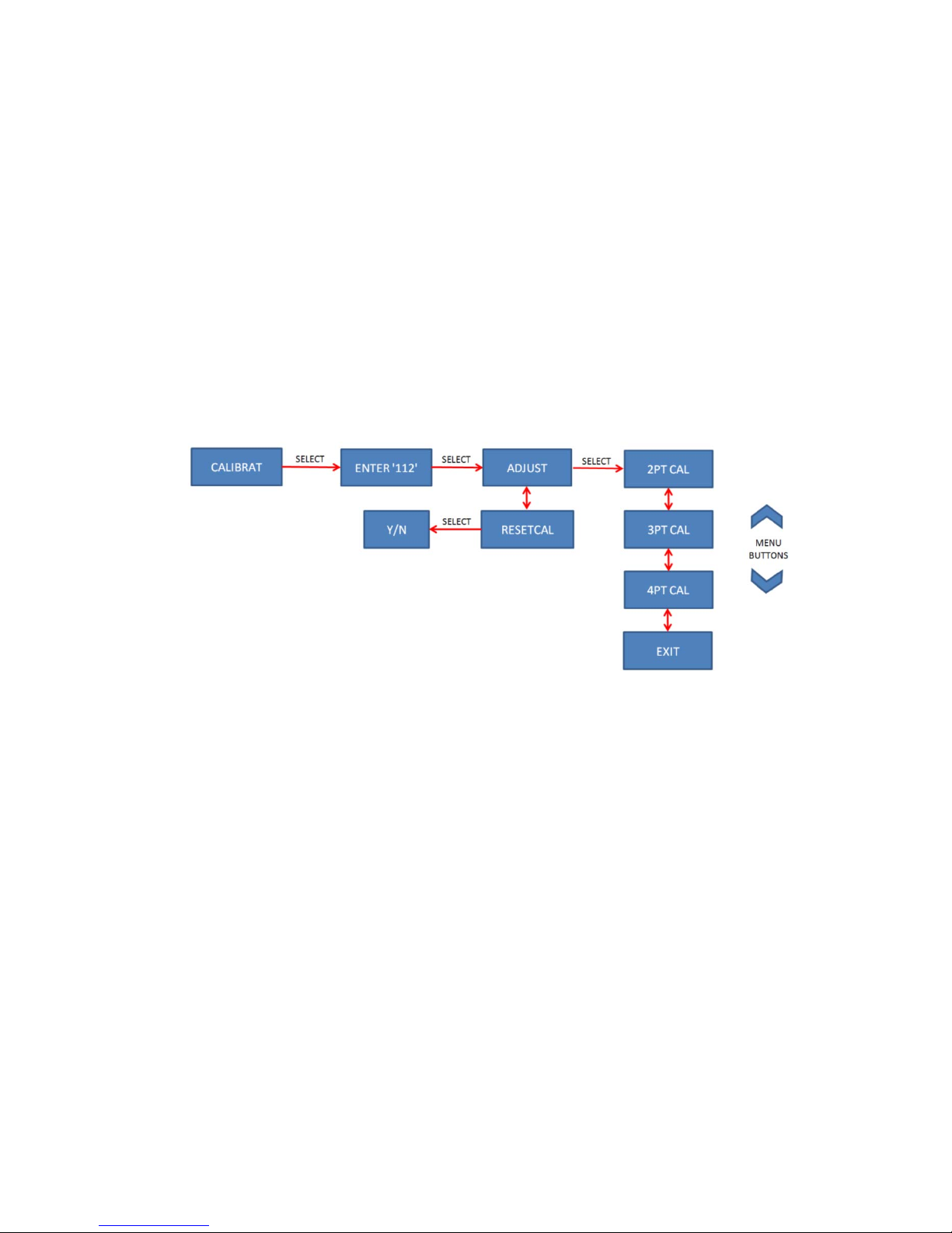
которая относительно близка к типовой температуре жидкости, для которой производятся измерения,
при этом точность будет выдерживаться в таком заданном диапазоне. Например, если температура
жидкости, для которой производятся измерения, обычно ниже 38 °C, то тарировку по верхней точке
можно проводить приблизительно при такой же температуре. Точность показаний температуры в
области выше
этой точки тарировки обеспечить невозможно.
Для тарировки необходимо выполнить перечисленные ниже поэтапные действия.
1. Включите режим тарировки, выбрав для этого пункт CALIBRAT (тарировка) в меню выбора. После
выбора данного пункта запрашивается пароль из 3 цифр. Выбор каждой цифры осуществляется с
помощью кнопок «вверх» и «вниз». После выбора необходимой цифры нажмите кнопку выбора,
чтобы перейти к выбору следующей цифры. Когда будет выбрана третья цифра, нажмите
выбора, чтобы перейти в режим тарировки. В случае ввода неправильного пароля на дисплее
появляется надпись FAIL (ошибка) и прибор возвращается в режим измерения температуры. При
успешном входе в режим тарировки на дисплее мигает слово «CAL» (тарировка). Пароль для входа
в режим тарировки: 112
2.
В меню тарировки выберите пункт ADJUST (корректировать) и задайте желаемое количество точек
тарировки. С помощью кнопки выбора выберите тип тарировки: 2PT CAL (двухточечная), 3PT
CAL (трехточечная) или 4PT CAL (четырехточечная).
ПРИМЕЧАНИЕ. Если пользователь не готов ко входу в режим тарировки, нажмите кнопку
EXIT (выйти).
3. Прибор находится в режиме корректировки. На дисплее отобразится
1-ю точку). С помощью кнопок «вверх» и «вниз» выберите другую точку для корректировки или
нажмите кнопку CANCEL (отмена). При нажатии кнопки CANCEL (отмена) происходит выход из
процедуры тарировки, при этом активируются значения от предыдущей тарировки.
ADD PT1 (добавить 1-ю точку) — точка самой низкой температуры.
ADD PT2 (добавить 2-ю точку) —
следующая точка более высокой температуры.
ADD PT3 (добавить 3-ю точку) — следующая точка более высокой температуры (используется
только в режиме трехточечной или четырехточечной тарировки).
ADD PT4 (добавить 4-ю точку) — точка самой высокой температуры (используется только в
режиме четырехточечной тарировки).
ADJ DONE (корректировка завершена) — сохранение настроек и выход из режима тарировки (все
температурные точки скорректированы и
являются допустимыми).
CANCEL (отмена) — выход из режима тарировки без сохранения настроек.
Выберите точку, по которой необходимо провести корректировку, и нажмите кнопку выбора, чтобы
начать. На дисплее отобразится текущая температура, а также будут мигать значок «CAL»
(тарировка) и номер корректируемой точки.
надпись ADD PT1 (добавить
кнопку
Октябрь 2017 г., JK
Page 36

ПРИМЕЧАНИЯ.
o Тарировка может проводиться с точностью до сотых долей градуса.
o Для увеличения и уменьшения показаний, отображаемых на дисплее, используются кнопки
«вверх» ии«вниз».
o При удержании кнопки «вверх» или «вниз» значение изменяется с шагом 0,1 градуса.
o При кратковременном нажатии (продолжительностью менее 0,5 секунды) кнопки
«вверх
» или «вниз» значение изменяется с шагом 0,01 градуса после каждого такого
нажатия.
o После стабилизации показаний температуры стрелки на дисплее мигнут 3 раза.
o Прежде чем выбрать пункт ADJ DONE (корректировка завершена), необходимо
сохранить все точки. Если сохранены не все температурные точки или если точки
выбраны не в порядке повышения температуры, на
дисплее отобразится надпись DATA
ERR (ошибка данных) (например, PT1 = 0C, PT2 = 50C, PT3 = 120C).
o В режиме тарировки температура отображается на основании кривой предыдущей
тарировки.
o Для возврата прибора к заводской тарировочной кривой используется функция RESETCAL
(сброс тарировки) (при этом все равно потребуется тарировка (корректировка)).
o Функцию RESETCAL (сброс тарировки до заводских значений) необходимо использовать,
если трехпроводной
термощуп был заменен двухпроводным или если вследствие
предыдущей тарировки показания прибора выходили за пределы допустимого диапазона.
4. После стабилизации температуры измерьте фактическую температуру в ванной эталонным
термометром и с помощью кнопок «вверх» и «вниз» скорректируйте показания на приборе так,
чтобы они соответствовали фактической температуре. Когда значение температуры на приборе
совпадет с фактической температурой, нажмите кнопку выбора, чтобы сохранить настройки. На
дисплее отобразится надпись SAVE (сохранить) или EXIT (выйти). При выборе команды EXIT
(выйти) произойдет возврат в меню ADD PT1 (добавить точку 1). При выборе команды SAVE
(сохранить) произойдет переход к корректировке следующей температурной точки, т. е. на дисплее
отобразится надпись ADD PT…
(добавить точку № ...). С помощью кнопок «вверх» и «вниз»
выберите другую точку для корректировки или нажмите кнопку CANCEL (отмена). При нажатии
кнопки CANCEL (отмена) происходит выход из процедуры тарировки, при этом активируются
значения от предыдущей тарировки.
o ПРИМЕЧАНИЕ. При выборе команды SAVE (сохранить) на дисплее со значением
температуры будет отображаться
предыдущее показание, пока не завершится тарировка.
o ПРИМЕЧАНИЕ. Если нажать кнопку SAVE (сохранить) до стабилизации температуры, на
дисплее отобразится надпись NOT STABLE (нестабильная). Дождитесь стабилизации
температуры и сохраните значение.
5. Поместите термощуп в следующую ванну и повторите шаг 4. После сохранения точки самой
высокой температуры на дисплее будет мигать надпись READY (готово
), то новые настройки есть
вступят в силу. После этого восстановятся стандартные рабочие функции кнопок прибора. При
выключении прибора настройки тарировки сохраняются во флеш-памяти. Автоматические
выключение прибора не предусмотрено. При выключении прибора вручную происходит сохранение
данных тарировки.
ThermoProbe, Inc.
112A JETPORT DR.
PEARL, MS 39208 (штат Миссисипи), США
Тел.: +1 601 939 1831
Факс: +1 601 355 1831
sales@thermoprobe.net
www.thermoprobe.net
Октябрь 2017 г., JK
Page 37

ИНСТРУКЦИЯ ПО ТЕХНИКЕ БЕЗОПАСНОСТИ. МОДЕЛИ
TP7-D И TP9-A РЕД. 102017
Данные приборы производства компании «Термопроб» предназначены для использования как в опасной
(потенциально пожароопасной или взрывоопасной), так и в безопасной среде в сухих условиях при
температуре от –20 до 40 °C.
Данные приборы не предназначены для использования в стационарных установках вне помещения и в
условиях обледенения.
тепла, ударов и т. д.), необходимо использовать дополнительные средства обеспечения безопасности.
Пользователь должен в рабочем объеме знать правила техники безопасности.
a) Пользователь должен досконально знать среду, подлежащую измерению, и меры предосторожности,
которые необходимо соблюдать при обращении с ней.
b) Прибор должен проверяться на предмет отсутствия существенных повреждений, а также на предмет
комплектности (в т. ч. наличия кабеля заземления), уровня заряда батарей и т. д. По необходимости
проверяется погрешность измерений. Прибор не должен
обнаруженные неисправности.
c) Прибор (в частности, кабель и термощуп) должен быть чистым: это обеспечит безопасность и простоту
его эксплуатации.
d) Необходимо оценить участок проведения замеров на предмет первичных и вторичных рисков.
e) Обслуживание прибора допускается только после извлечения из него источников питания.
f) Во избежание утраты
устройств, за исключением батарей, должен осуществлять персонал компании «Термопроб» или
уполномоченных обслуживающих организаций. См. также раздел «Ремонт уполномоченными лицами».
g) В целях снижения риска возникновения пожара или взрыва данный прибор должен быть заземлен на
сосуд, как описано в стандарте IEC/EN 60079-14 (п. 6.3.2 «e»), до и во время
пока термощуп не будет полностью извлечен из данного сосуда.
h) Прибор должен оставаться заземленным (замкнутым на землю) с помощью соединителя, входящего в
комплект поставки, если возможно наличие опасной атмосферы или создание электростатического разряда
(например, при
ВНИМАНИЕ! Если какая-либо часть прибора накапливает электростатический заряд в потенциально
опасной зоне, необходимо, руководствуясь правилами своей организации, проверить и очистить данную
зону от любых опасных газов, прежде чем пытаться замкнуть прибор на землю (заземлить). Если такую
очистку провести
приборе заряд естественным путем рассеялся, прежде чем пытаться замкнуть прибор на землю (заземлить).
В зависимости от особенностей среды данный процесс может занять несколько часов.
размотке и скручивании кабеля термометра либо при наполнении или опорожнении сосуда).
Если возможно чрезмерное воздействие на приборы внешних факторов (вибрации,
использоваться, пока не будут устранены все
юридической силы сертификатов ATEX/IECEx и прочих замену элементов
помещения его в данный сосуд,
невозможно, необходимо выждать достаточное время, чтобы любой накопившийся в
РЕКОМЕНДАЦИИ
Проблемы, связанные с агрессивными веществами и средами: Учитывайте наличие агрессивных веществ и
возможную необходимость в дополнительных средствах защиты.
Каустическая сода, высокоосновные и кислые вещества оказывают разрушительное действие на
алюминиевые и медные зажимы и провода. Внешние поверхности узла, состоящего из датчика с кабелем,
выполнены из нержавеющей стали и фторполимерного материала. При чрезмерном
пластиковые элементы прибора могут расплавиться.
воздействии тепла
Октябрь 2017 г., JK
Page 38

СТАНДАРТЫ БЕЗОПАСНОСТИ, ПРИМЕНИМЫЕ К МОДЕЛЯМ TP7-D И TP9-A:
AEx ia IIB T4 Ga
Применимые стандарты: Орган или категория безопасности
IEC 60079-0:Ed 6, IEC 60079-11:Ed 6 IECEx
EN 60079-0:2012 + A11 3013, EN60079-11:2012 Европа: ATEX
ИСКРОБЕЗОПАСНОСТЬ
Искробезопасное оборудование определяется как «оборудование и проводка, неспособные в нормальных и в
нештатных условиях вырабатывать достаточно большую электрическую или тепловую энергию, которая
станет причиной воспламенения опасной воздушной смеси в ее наиболее легковоспламеняемой
концентрации» (ISA-RP12.6). С этой целью доступная мощность электрического оборудования,
используемого в опасной зоне, снижается до уровня, при котором не произойдет
присутствующих газов.
Для воспламенения или взрыва необходимо наличие горючего вещества, кислорода и источника возгорания.
Искробезопасность системы предполагает, что горючее вещество и кислород имеются в атмосфере, но
система сконструирована так, что электрической или тепловой энергии, присутствующей в определенном ее
контуре, при любых обстоятельствах недостаточно для воспламенения.
воспламенения
БАТАРЕИ
ПРЕДУПРЕЖДЕНИЕ.
Замена батарей должна производиться в безопасном месте.
Используйте батареи только разрешенного типа.
При установке батарей необходимо соблюдать правильную полярность, то есть полюс батареи,
обозначенный символом «+», должен совпадать с символом «+» на в батарейном отсеке.
Недопустимо устанавливать новую батарею вместе со старой.
Не допускается одновременное использование батарей разных
Не допускается устанавливать батареи так, чтобы их полярность друг относительна друга была
обратной; при такой схеме одна батарея заряжается от другой.
Ниже указаны ОФИЦИАЛЬНО ОДОБРЕННЫЕ батареи для моделей TP9-A и TP7-D.
Производитель Тип Артикул
«Дюраселл» AA (LR6) Щелочная MN1500
«Панасоник» AA (LR6) Щелочная LR6XWA
«Джи-пи» («Голд пик») AA (LR6) Щелочная GP15A
моделей или производителей.
Октябрь 2017 г., JK
Page 39
使用说明 - TP7-D和TP9-A
引言
本手册将介绍型号TP7-D和TP9-A便携式数字温度计设备的基本功能、使用和安全说明。
更换电池
电池电压低时,显示屏上将显示电池电量不足图标。
电池电压非常低时,背光灯将不再工作,同时显示屏上的电池电量不足图标将会“闪烁”。
发现电池电量不足后,请尽快在安全的地方更换电池。这可以确保背光灯工作,避免出现故障。电池显示
电量不足时,不要尝试校准仪器。
警告:
切勿在危险区域更换电池。
电池必须是经认可的正确型号。
安装电池时极性必须正确,确保电池的(+)端与印在电池盒上的(+)符号对准。
安装电池时极性不得颠倒,否则其中一个电池单元会向另一个单元充电。
新旧电池不得混用。不同型号或生产商的电池不得混用。
a)确保设备处于非危险区域并关闭电源。
b)用2号十字形螺丝起子拆卸固定TP7-D前盖的3颗螺丝,或者固定TP9-A前盖的2颗螺丝。
c)用1号十字形螺丝起子拆卸电池盖上的唯一一颗螺丝。拆下电池盖,将其中一块电池推向弹簧触点,并
将电池从支架上取出,然后取出剩余一块电池。
d)安装每块新电池时,要确保电池的(+)端与印在电池盒上的(+)符号对准。
e)将固定装置复位并重新安装盖子。
合格的TP9-A和TP7-D用电池如下所列:
制造商 型号
金霸王 AA (LR6) 碱性电池 MN1500
松下 AA (LR6) 碱性电池 LR6XWA
GP (金山工业) AA (LR6) 碱性电池 GP15A
零件号
10/2017, JK
Page 40

向上/向下菜单
键
授权维修
本手册范围之外的服务建议由ThermoProbe, Inc.公司或其授权分销商提供。
如要观看正确使用本设备的视频,请访问www.thermoprobe.net。请参阅美国石油学会计量标准第7.2.章。
用户界面
向上/向下菜单键
电源/选择键
存储器读数图标
温度指示箭头
校准点指示器
电池电量低指示器
10/2017, JK
Page 41

电源键
按一下电源键,就会打开设备。(注意:最近一次按键操作20分钟
直到显示“关闭”,将关闭设备。
:
后,设备将自动关闭。)按下“电源”键
选择菜单
使用“向上/向下
LOG(记录):保存当前稳定温度,最多保存4个读数
C-F:
DECIMAL(小数位):选择0.1或0.01显示分辨率
MEMORY(存储器) - 使用“向上/向下”键显示:
(使用CLR LOG清除保存的读数)
CALIBRAT(校准):进入校准/调整模式
(需要三位数密码:112) -
:
”菜单键来选择以下选项:
选择显示摄氏温度或华氏温度
最低读数
平均读数
最高读数
已存(已记录)读数1-10
见校准程序
背光灯
设备在低光条件下工作时,光电池将会探测到这种情况,并打开背光灯。
温度记录
记录温度前,温度必须保持稳定。当温度读数稳定时,显示箭头将闪烁3次。
如果您希望记录温度,按一下“向下”键直至显示LOG(记录)。按一下“选择”键,保存读数。如果显示“LOG
1-10”,则表示确认已保存一个读数。这个过程可以重复,直至保存10个读数。
可以从“存储器”菜单中访问已记录的温度。记录的温度显示时间带有LOG图标和对应以前记录读数的前缀(
1、2、3、4、5、6、7、8、9、0)。向上/向下键可用来逐个阅读这些读数。选择EXIT(退出)返回温度显
示。
即使设备关闭,已记录读数也会保留。进入菜单“存储器”部分,然后选择CLR
LOG(清除记录)可清除已记录读数。在读数清除之前,不能记录新读数。
USB存储器
电路板上有个微型USB接口,允许访问校准和已记录数据。
警告:不得在危险地方访问电路板。
最低、最高和平均读数
通过“存储器”菜单可以访问最低、最高和平均读数。这些读数分别由显示器上的LOW、AVG或HIGH图标来表
示。这些读数与记录读数无关,而由设备启动时的温度决定的。这些读数在设备关机后被删除。
显示代码
10/2017, JK
Page 42
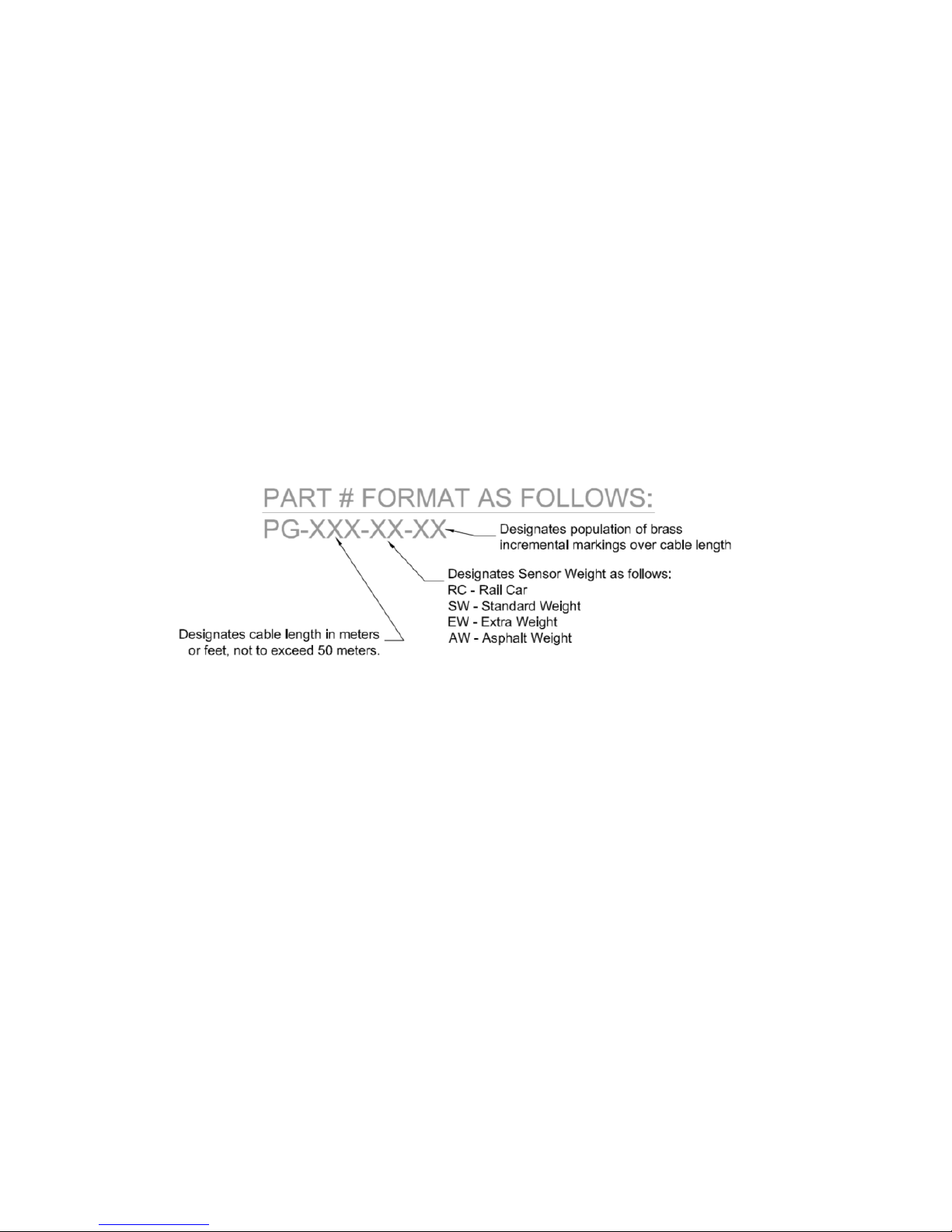
OPEN CKT -
表示传感器在其工作温度范围之上工作,探头组件由于某段电路被切割或断裂而处于开路状态,或者是在
电路板端子处电缆未正确插入。最常见的原因是电缆损坏。
SHORT CKT -
表示传感器在其工作温度范围之下工作,或者探头组件由于某段电路被压扁或切割而处于短路状态。最常
见的原因是电缆损坏。
NONE – 存储器没有保存的记录读数。
2 WIRE – 检测到一个2线探头连接。
3 WIRE – 检测到一个3线探针连接。
NO CAL – 设备未保存温度探头的校准数据。执行
调整/校准操作之后方可使用。
探头类型
TP7-D或TP9-A可使用2线或3线探头组件。
ThermoProbe
的替换探头组件有不同的结构形式。电缆长度可达50米或165英尺。每5英尺或1米设有标准黄铜标记。传感
器有4种重量类型。探头组件零件结构如下:
10/2017, JK
Page 43

更换探头组件
注意:
1)更换探头组件后需要重新校准设备。更换工作只应由有经验的人员完成,并且备有校准设备。
2) 请参照 IEC/EN 60079-19 (易爆气体环境 - 第 19
部分:设备维修、大修和改造)进行维修。
3)仅使用从 ThermoProbe, Inc.公司或其授权分销商处获得的更换探头组件。
a)首先按照“更换电池”指示说明步骤a至c卸下电池。
b)按压电路板上的端子夹,拆下电线,同时注意引线颜色编码排列。见图1。
白色 - 正极传感导线
绿色 - 电缆补偿线(不用于2线型号)
银色 - 负极传感导线和屏蔽线
c)将盖子和电路板放在一旁,并解开电缆组件上的应力消除结。
d)将电缆从组件上解开,并从橡皮环中拉出电缆。
e)将新电缆线穿过橡皮环,然后将电缆从橡皮环处拉出几英寸。
f)在橡皮环处给电缆打个简单的反手结用以消除应力,然后把绳结拉到橡皮环处。
g)在电路板上,按下端子夹把手,根据端子色码插入新的引线。标签上说明如何连接2线探头和3线探头(
包括绿色线)。见图1。
h)重新安装电池和盖子,并重新缠绕电缆组件。
i)执行校准(见校准程序)。
图1:探头组件引线连接
10/2017, JK
Page 44

校准程序
校准模式只能由配备适当设备的合格人员使用;否则,校准的完整性可能会受到损害。请仔细阅读
以下操作说明。
至少需要2个点来进行调整。(两点校准)。可以取更多点(3点或4点校准)来校准较大温度区间
(如0°F至300°F),或者如果您希望匹配区间内的特定点位。区间最低和最高点应该包括在内。必
须备有适合设备来校准每个点位。
如果显示电池电量低,不要试图校准设备,因为新的校准值可能不能正确地保存到存储器中。
请参考API 7.2或其他公认的常规校准验证推荐标准。
不得在任何被认为是危险的环境中进行校准。
所需设备:
带有基准温度计的冰浴池或其他低温浴池。
温度在20°C(约68°F)至90°C (约194°F)的热液浴池,带有基准温度计。(见须知)*
可选约150°C/300°F的高温油浴池,带有基准温度计
*
有限校准须知:如果不需要使用设备的整个量程,那么可以在所测量液体常温附近的温度进行2点高位
调整,这样就可以保持有限量程内的精度。例如:如果要测量的液体产品温度通常不到38°C(约100°F
),则可以在这个温度附近进行“高点”校准。这个校准点之上的温度精度无法保证。
如要校准,请按照如下步骤操作:
1. 前往选择菜单的CALIBRAT,进入校准模式。选择该选项时,设备将提示用户输入一个3位数的密码
。使用“向上/向下”键调整各个数字。设置好正确的数值之后,按下“选择”键就可以进入下一个数
字。三个数字设置好之后,按下“选择”键进入校准模式。如果输入的密码不正确,将会显示FAIL(
2. 在校准菜
失败),设备将返回到温度模式。进入校准模式后,显示屏上的“CAL”图标将会闪烁。
码是:
CAL(2点校准)、 3PT CAL(3点校准)或4PT CAL(4点校准)。
112
单中选择ADJUST(调整),然后选择需要校准的点数。使用选择键选择2PT
校准模式密
10/2017, JK
Page 45

注意:如
3. 设备现在进入调整模式。显示屏将显示ADD
PT1(添加点位1)。可用“向上/向下”键选择不同点位进行调整或CANCEL(取消)。如果选择CANCE
L(取消)选项,则退出校准程序,同时之前的校准值将会重新激活。
ADD PT1(添加点位1)= 最低温度点位
ADD PT2(添加点位2)= 下一个更高温度点位
ADD PT3(添加点位3)= 下一个更高温度点位(仅用于3点校准或4点校准模式)
ADD PT4(添加点位4)= 最高温度点位(仅用于4点校准模式)
ADJ DONE (调整完毕)= 保存并退出校准模式(所有点位已调整且有效)
CANCEL(取消) = 不保存退出校准模式
选择调整点位并按下“选择”键开始。将会显示当前温度,而且CAL图标和调整点编号将会闪烁。
注意:
o 校准精度可以达到百分之一度。
o 可以使用向上/向下键来增加或减少显示读数。
o 按住“向上/向下”键将会以0.1度的幅度
o 如果点按“向上/向下”键的时间不到0.5秒,则每按一次将会以0.01度的幅度进行调整。
o 当温度读数稳定时,显示箭头将闪烁3次。
o 必须保存所有温度点之后,方可选择ADJ
DONE(调整完毕)。如果没有保存所有温度点或者温度没有逐点升高,那么将会显示 DATA
ERR(数据错误)消息。(例:PT1 = 32F、PT2 = 120F、PT3 = 250F)
o 处于校准模式时,温度显示将以之前的校准曲线为依据。
o RESETCAL(复位校准)功能可用来将设备复位至工厂校准曲线。(依然需要校准/调整)。
果用户还没有准备好进入校准模式,则可以选择EXIT(退出)选项。
进行调整。
o RESETCAL(复位至工厂校准)功能应用于以下情形:探头更换为2线组件,而不是3线组件
,或者之前的校准导致设备读数超出公差范围过大。
4.
温度稳定下来之后,使用基准设备检查浴池的实际温度,并使用“向上/向下”键将设备调整到实际
温度。如果设备温度与实际温度匹配,则按一下“选择”键保存设置。显示屏将显示SAVE(保存)或
EXIT(退出)。如果选择EXIT(退出),则会返回至ADD
PT1(添加点位1)菜单。如果选择SAVE(保存),则显示屏将会进入下一个温度调整点,显示ADD
PT...(添加点位...)。可用“向上/向下”键选择
ANCEL(取消)选项,则退出校准程序,同时之前的校准值将会重新激活。
o 注意:如果选择SAVE(保存),温度显示将会回至之前的读数,直至完成校准为止。
o 注意:如果温度尚未稳定下来就选择SAVE(保存),显示屏将会显示NOT
STABLE(不稳定)。请等待温度稳定下来之后再保存。
5. 将探头移到下一个浴池,重复步骤4。保存最高温度点位之后,显示屏将会闪烁显示READY(就绪)
,于是新的校准设置将生效。按键现在将恢复正常的操作功能。设备关闭时,校准设置将保存到闪
存中。设备不会自动关闭。手动关闭设备,以保存校准数据。
ThermoProbe
112A JETPORT DR.
PEARL, MS 39208
电话:+1 601.939.1831
传真:+1 601.355.1831
sales@thermoprobe.net
www.thermoprobe.net
不同点位进行调整或CANCEL(取消)。如果选择C
, Inc.
10/2017, JK
Page 46

安全说明 - TP7-D和TP9-A 版次:102017
这些ThermoProbe设备设计工作环境为干燥条件下环境温度为20至40°C的危险(可燃或易爆)或安全区域。
这些设备不得用于永久性户外设施或在结冰条件下使用,也未经过结冰条件测试。在设备可能暴露于过度
的外部应力(如振动、热、冲击等)环境下时,应采取额外的保护措施。使用者必须具备适当的安全要求
知识。
a)使用者必须全面了解所测量的产品,并且必须了解测量材料时需要采取的安全措施。
b)应检查设备是否存在严重缺陷;检查设备是否完整(包括接地/连接电缆),电池电量是否充足等。必
要时,检查测量精度。如果发现有任何缺陷,在进行维修之前不得使用设备。
c)设备,尤其是电缆和探头应该保持干净,以保证安全,易于使用。
d)应该评估物理测量位置是否存在一级和二级风险。
e)必须切断电源之后,方可进行任何维护工作。
f)除电池以外的部件调换可能会影响ATEX/IECEx或其他认证,并且只能由ThermoProbe或其合格的服务供
应商进行。也请参阅“授权维修”部分。
g)为减少火灾或爆炸危险,根据IEC/EN 60079-14的第6.3.2
e)条规定,在进入容器之前和期间,设备必须与容器连接并保持连接,直至传感探头完全从容器中取出。
h)设备在以下情况下必须保持接地:只要可能存在危险环境,可能发生静电充电情况,如
温度表电缆解开/缠绕时,或加注或清空油箱时。
警告:如果设备的任何部分在潜在危险的地方被静电充电,请根据公司政策在该区域检测和清除任何危险
气体,然后再将设备接地。如果不可能这么做,那么在尝试接地之前,让设备有足够的时间自然消除任何
电荷。取决于大气环境,这可能需要几个小时:
指导性说明
侵蚀性物质和环境问题:要注意侵蚀性物质,可能需要采取额外的保护措施。
苛性钠、强碱性和酸性物质会侵蚀铝和铜接地线和接地线夹。传感器电缆组件具有不锈钢和氟聚合物材料
外表面。暴露于过热环境可能会使得设备的塑料部件熔化。
10/2017, JK
Page 47
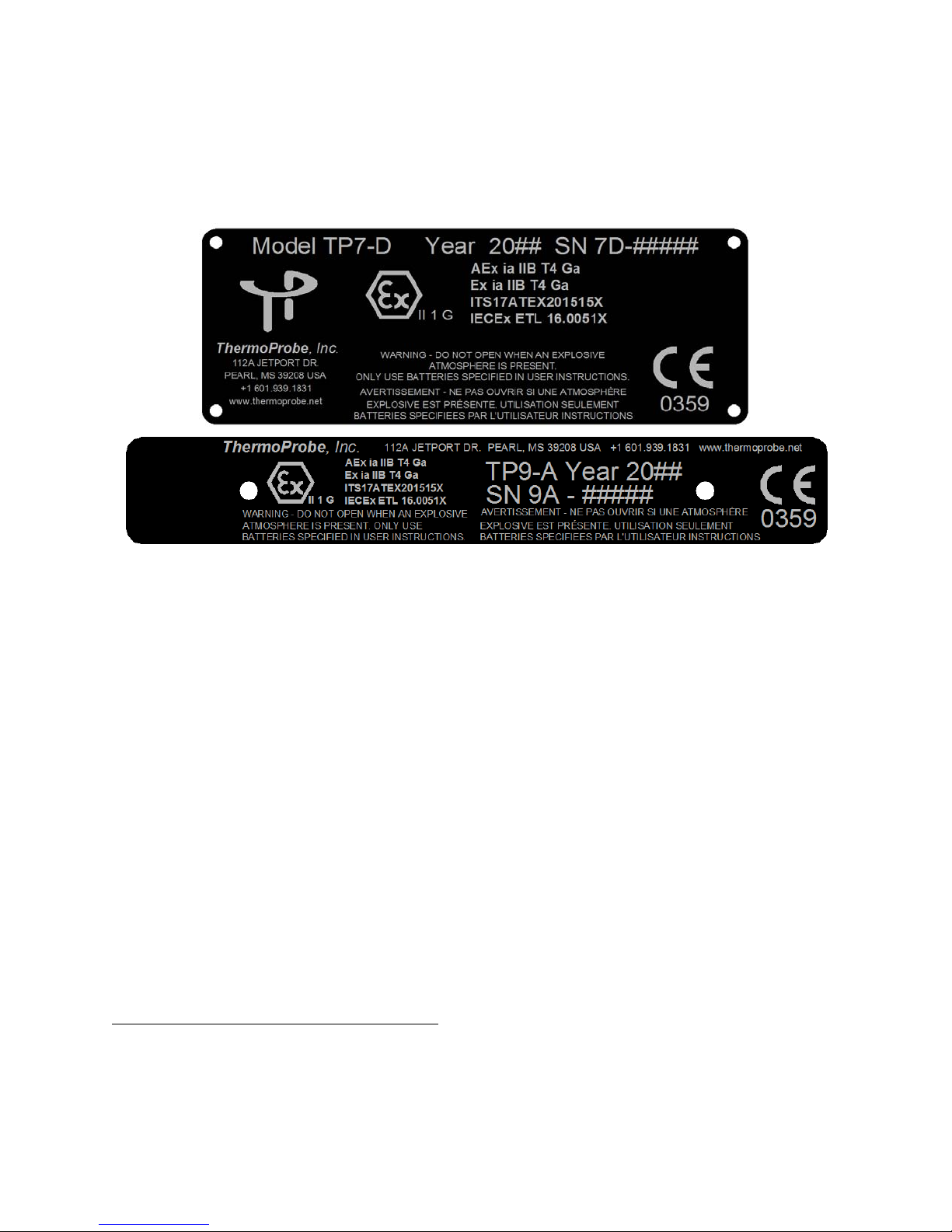
TP7-D和TP9-A安全认证:
AEx ia IIB T4 Ga
适用标准为: 机构或安全认证名称
IEC 60079-0:Ed 6, IEC 60079-11:Ed 6 IECEx
EN 60079-0:2012 + A11 3013, EN60079-11:2012
欧洲:ATEX
内在安全
内在安全的设备被定义为“在正常或异常条件下不能释放足够的电或热能导致特定有害大气混合物在其最容
易点燃的浓度点火的设备和线路。”(ISA-
RP12)实现方式是将危险区域的电力设备的电力供应限制在点燃气体的水平之下。
如要发生火灾或爆炸,燃料、氧气和火源三者缺一不可。内在安全的系统假设燃料和氧气存在于大气中,
但是设计系统时确保特定设备回路的电能或热能决不会有足够的能量引起点火。
电池
警告:
切勿在危险区域更换电池。
电池必须是经认可的正确型号。
安装电池时极性必须正确,确保电池的(+)端与印在电池盒上的(+)符号对准。
新旧电池不得混用。
不同型号或生产商的电池不得混用。
安装电池时极性不得颠倒,否则其中一个电池单元会向另一个单元充电。
合格的TP9-A和TP7-D用电池如下所列:
制造商 型号
金霸王 AA (LR6) 碱性电池 MN1500
松下 AA (LR6) 碱性电池 LR6XWA
GP (金山工业) AA (LR6) 碱性电池 GP15A
零件号
10/2017, JK
 Loading...