

Page 1

TThheerrm
moo
PPrroobbee,,
IInncc..
RECOMMENDED OPERATION
To properly use this instrument the operator
should be familiar with API 7 and the
International Safety Guide For Oil Tankers and
Terminals.
SPOOL-LOCK
To avoid unwanted dispatch or tangling of
the cable, a threaded spool-lock is located on
the case where the ground wire is attached.
When using the instrument simply turn the
screw out so that the cable spool can freely
spin.
AUTO-SHUTOFF
The TP7 is equipped for automatic shut off after
approximately 2 minutes. Battery life is
extended since the unit cannot be left on
unattended.
LOW BATTERY ALERT
LO - Battery Voltage Low
When the TP7 is switched on, it will
immediately check the status of the battery. A
low battery situation will result with a flashing of
“LO” to the display for a few seconds before the
temperature reading is available. The battery
needs to be replaced soon after the warning is
observed, this is especially important if the unit
will be used in low light situations where the
backlight will be illuminated.
BATTERY REPLACEMENT
PROCEDURE
PERFORM BATTERY REPLACEMENT ONLY IN
AN AREA KNOWN TO BE NONHAZARDOUS.
APPROVED BATTERIES. See Identification plate
for approved batteries.
Remove the three-faceplate screws; turn the
unit upside down allowing the faceplatecircuit board module to fall into your hand.
The battery is then readily accessible for
manual replacement.
TP7 USER MAINTENANCE
DISPLAY CHECK
When the instrument is first turned on, the display
will briefly show all possible character segments.
This will look like: 888.8. If any segments fail to
show, the instrument should not be used and it is
likely that the glass display is cracked.
ERROR CODES
Two error codes have been established to
provide the user information in case a
maintenance situation has occurred.
E1 - Short Circuit or Under Range
E2 - Open Circuit or Over Range
“E1” When this happens, one of two
situations has exists. In most cases, the probe
circuit has been shorted; usually meaning the
cable has been smashed at some point.
Secondly, “E1” represents a below range
reading. The temperature being gauged is
below the measurable specified range.
“E2” When this occurs, there are also two
possible situations. The first and most likely is
that the probe circuit has a discontinuity. This
may occur as a result of a cut cable, bad
termination at the circuit board or damaged
sensor. Check the cable terminal making sure
the wires are correctly inserted into the
connector on the board. Secondly, “E2”
represents an over range reading, meaning the
temperature at the sensor has risen above the
measurable specified limit of the unit.
°F/°C DISPLAY UNITS
The TP7 may display the temperature reading
in Fahrenheit or Celsius units. To change the
readout from one unit to the other remove the
switch plate and slide the circuit board through
the top. The selector is located above the
battery and the letters F and C can be seen on
the surface of the board. Place the selector
shunt on the center and upper pin for °F and
center and lower pin for °C. See illustration on
next page. There is no need for recalibration if
the there is a change in the temperature units.
Page 2
REPLACING THE PROBE ASSEMBLY
When attaching a new probe assembly to circuit, it is necessary
to pay attention to the polarity of the probe.
Black Wire (shielding with shrink wrap) = (-)
White Wire (signal lead) = (+)
Polarity markings are located on the circuit board in front of the
finger connector. See illustration.
Reversed wires will inhibit proper probe grounding and may
cause false readings.
If a probe assembly is replaced with one of the same length, the
calibration will be within + 0.2 °F at 32 °F and within +0.6 °F
at 200 °F. It is recommended that a recalibration be performed
to make the instrument as accurate as possible.
CALIBRATION
The TP7 design allows extended calibration periods. If
accuracy is not within specifications check cable integrity and
inspect the circuit board for possible corrosion, particularly near
the cable terminals. Calibration adjustments will not properly
correct these problems.
To verify/calibrate the instrument to the best possible accuracy
over a wide range, the following items are necessary:
-A certified thermometer.
-A circulated refrigerated bath, with a temperature near:
32.0 °F/ 0.0 °C (Bath 1)
-A circulated hot bath with a temperature:
190-200 °F /88-93°C (Bath 2)
-Small flat head adjustment screwdriver or similar tool.
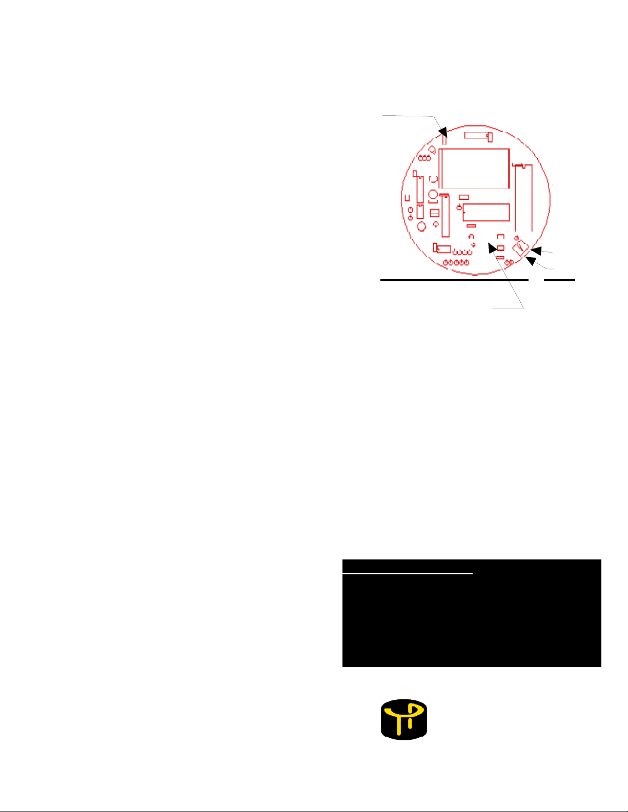
1. Remove the 3 faceplate screws and lift assembly from housing.
2. Using the illustration (to the right) find the adjustment trims.
3. Adjust the ZERO with the probe assembly in Bath 1.
4. Adjust the SPAN with the probe assembly in Bath 2.
5. Repeat several times or until no adjustment is necessary.
FACEPLATE-CIRCUIT BOARD MODULE
F / C
SELECTOR
(Other Side of
Board)
- +
95.8F
SPAN
ZERO
PROBE WIRE
TERMINALS
( Other Side)
AUTHORIZED REPAIR:
It is recommend that service done beyond
the scope of this article be presented to
ThermoProbe Inc. or one of its distributors.
Any servicing by unauthorized parties may
void the Intrinsic Safety and the warranty.
TThheerrmmo
112-A Jetport Drive
Pearl, MS 39208 USA
Voice: +1 601-939-1831
Fax: +1 601-355-1831
www.thermoprobe.net
o
PPrroobbee,, IInncc.
.
 Loading...