

Page 1

TP2-C & TP5-C User Manual for Maintenance and Calibration.
See “Instructions for Use” for safety information.
BATTERY CHECK
When the voltage of the batteries is low, the device will indicate “Lo bAtt” on the display before resuming normal display functions.
When the batteries are low the backlight will not operate in order to conserve power while the user completes his operations. Replace
batteries as soon as possible in a safe location after “Lo bAtt” is noticed, this will ensure backlight operation, and avoid possible
malfunctioning. Do not attempt to calibrate the instrument if the “Lo bAtt” has been displayed since the new calibration values may
not be properly stored to memory.
REPLACING BATTERY
a) Move into a non-hazardous area.
b) Remove the screws holding the back cover on the TP2-C or front cover of TP5-C.
c) On TP2-C unfasten battery retaining device, push one battery towards the spring contact and lift battery up from the holder, then
remove the remaining battery.
d) Mount each new battery by aligning the (+) end of the battery with (+) embossed in the battery case.
e) Reinstall the cover plate.
PROBE ASSEMBLY ERROR CODES
ErrHI indicates the sensor is operating above its temperature limit, the Probe Assembly is open circuited from a cut or broken
section, the sensor is open or the cable is not properly inserted at the circuit board terminal. The most common event is a damaged
cable.
ErrLO indicates the sensor is operating below its temperature limit, the Probe Assembly is short circuited due to a smashed or cut
section, or the cable wire polarity is reversed at the circuit board terminal. The most common event is a damaged cable
.
REPLACING THE PROBE ASSEMBLY
Replacement should only be done if calibration equipment is available and personnel experienced with this procedure.
a) First follow above instructions and remove batteries.
b) On the TP2-C remove the cable from the case and remove the back cover. On the TP5-C remove the cable and left side cover.
c) Push the terminal clamps back and pull out the wires noting the color code
d) Remove the stra in relief knot, pull the cable out from the outside remove the assembly.
e) Push the new cable wire through the rubber gro mmet and then pull several inches of cable into the inside of the case.
f) Tie a simple square knot in the cable and then push it against the case.
g) Push the terminal clamps back and push the wires in, no ting the color code.
h) Replace the cover, install the cable and calibrate.
CALIBRATION PROCEDURE
Refer to API 7 for Calibration Verification Procedures:
Calibration is not to be performed in any environment considered to be hazardous.
ThermoProbes should be calibrated at least annually to keep the highest accuracy. Please check for accuracy error against a stable
temperature bath. Calibration requires at least two precision temperature reference points, for example; 0.0°C (32.0°F) and 90.0 °C
(194°F) stable liquid calibration baths or similar certified temperature calibration equipment.
The device has the option of being calibrated at 2, 3 or even 4 points. The 3 or 4 point calibration is only necessary when a probe
assembly has been replaced or it is necessary to ensure high accuracy at 150°C/300°F and above. Normally a 2 point calibration will
serve to provide high accuracy below 100°C/200°F and enough accuracy to meet the API requirements for above 100°C/200°F.
Equipment needed:
• Ice Bath or other low temperature bath with certified reference thermometer.
• Warm to hot fluid bath between 20°C (approx 68°F), or higher up to 90°C (approx 194°F) with certified reference
thermometer. (see Note)*
09/14/06 LB, 06/07/06, 5/14/06, 01/15/06, 01/11/06, 12/15/05, 11/23/04, 11/16/04, 10/04 LB
Page 2
• Optional high temperature oil bath at about 150°C/300°F and certified reference thermometer.
*Note for limited calibration: If entire range capability of instrument is not required, the 2 point high adjustment can be made at
a temperature relatively close to the common temperature of the liquid measured and accuracy will be maintained within the
limited range. For example: If liquid product to be measured is commonly less than 38°C (approx. 100°F), then a “high point”
calibration can be made near that temperature. Temperature accuracy above this calibration point cannot be assured.
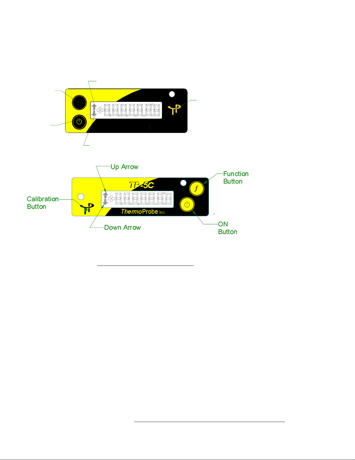
Up Arrow
Function
TP-2C
Button
f
TP-2C
Calibration
Button
ON
ThermoProbe
Inc.
Button
Down Arrow
Calibration Mode
• The calibration mode should only be accessed by qualified personnel with proper equipment, otherwise calibration integrity
may be compromised. Read the following instructions carefully.
• A 2-Point, 3-Point or a 4-point calibration can be performed. A third or fourth point is only necessary when high accuracy is
required at temperatures of 300°F and higher. You must have the proper equipment for every point of calibration.
• Do not attempt to calibrate the instrument if the “Lo bAtt” has been displayed since the new calibration values may not be
properly stored to memory.
• The Calibration Mode can be exited in two ways. If the user is not ready to enter the calibration mode as described in Step 1
below, the CAnCEL option can be chosen. If a user needs to end a calibration before completing it then STEP 3 below
provides and option to safely exit the operation and revert to previously stored calibration values. .
To calibrate proceed with the following steps:
1. A hidden Calibration Button is located on the front overlay underneath the ThermoProbe logo (see diagram above).
When the instrument is on, first press and hold the “f” Button, and then press and hold the hidden Calibration Button until the
display scrolls through the options 2Pt CAL, 3PtCAL, 4PtCAL, CAnCEL. When the desired option is displayed, release the
buttons.
2. The device is now in calibration mode.
The last character on the right side of the LCD will now be blinking “A” representing the lowest temperature calibration point.
“b” = the next higher temperature point
“C” = the next higher temperature point (only used in 3-point calibration or 4-point calibration mode)
“d” = the highest temperature point (only used in 4-point calibration mode)
While at each temperature calibration point the arrows will flash 3 times when the temperature reading stabilizes
.
09/14/06 LB, 06/07/06, 5/14/06, 01/15/06, 01/11/06, 12/15/05, 11/23/04, 11/16/04, 10/04 LB
Page 3

Calibration can be performed to hundredths of a degree.
The “On” Button increases the display reading, the “f” Button decreases the display reading.
Holding the “On” Button or the “f” Button adjusts 0.1 degrees increments.
Momentary Presses of the “On” Button or the “f” Button for less than 0.5 seconds adjusts 0.01 degrees for every press.
When you leave calibration mode the display remains in hundredths for that session only to allow you to re-check the temperatures.
Once you have turned the device off, the display will only show in tenths.
3. Once the temperature has stabilized, using a certified reference device check the actual temperature in the bath and use the “On”
Button or the “f” Button to adjust the device to the actual temperature. The “On” button will decrement the readings and the “f”
Button will increment the reading. Once the device temperature matches the actual temperature, press the Calibration Button to
save the setting. The display will scroll "SAUE" or “CAnCEL”. If the “SAUE” option is chosen the blinking letter will change to
represent the next temperature level (A => b). If the “CAnCEL” option is chosen then the calibration procedure is exited and the
prior calibration values are re-activated.
4. Move the probe to the next bath and repeat step 3. After you save the highest temperature point the display will flash "rEAdY"
and the new calibration settings will be in effect. The buttons will now resume their normal operating functions. The calibration
settings are saved to flash memory when the device is turned off. The unit will not turn off automatically, manually turning the unit
off saves the calibration data.
Ensure that your calibration efforts are saved by shutting the instrument off now
.
Function Button Error Code
1. nO rEAd -the user accessed "List" or "At" before saving temperatures.
Calibration Error Codes
1. nO CAL - This is seen after the instrument is turned on when no calibration data has been saved yet. The device must be
calibrated before using.
2. CAL Err2 - This is seen after the instrument is turned on when there is a flash memory error or the calibrations data is corrupted.
When this error is displayed the device will inaccurately display temperatures without using any calibration data. This error probably
indicates a device error. The user should contact the distributor or ThermoProbe, Inc.
3. CAL Err3 - This is seen after the instrument is turned on when calibrations data reads OK, but is invalid. This could be an error in
calibrating the device. When this error is displayed the device will read temperatures without using any calibrations data. This error
could occur as a result of not saving the low or mid temperature before moving the device to the next bath during calibration. The
device should be recalibrated.
09/14/06 LB, 06/07/06, 5/14/06, 01/15/06, 01/11/06, 12/15/05, 11/23/04, 11/16/04, 10/04 LB
TThheerrmmo
112-A Jetport Drive
Pearl, MS 39208 USA
Voice: +1 601-939-1831
Fax: +1 601-355-1831
www.thermoprobe.net
o
PPrroobbee,, IInncc.
.
 Loading...