

ThermoProbe TL2-A Instructions For Use Manual
TL2-A Instructions for Use
The TL2-A is an affordable high precision digital thermometer. It has been designed for use in both laboratory
and industrial applications. Additional video tutorials and information are included on the software USB flash
drive. Features of the TL2-A are as follows:
Configurable RTD and SPRT combinations (100Ω or 200Ω)
• Available 2 channel temperature measurement
• 0.001 degree resolution (0.0001 for Ω)
• Implements ITS-90 or Callendar-Van Dusen calibration coefficients
• Displays temperature in Celsius, Fahrenheit, Kelvin or Ohms
• Backlit, Large LCD character display
• USB Type ‘A’ PC interface
• USB Type ‘B’ flash memory interface
• User programmable relay output interface (Temperature triggered)
• Detachable AC power cord
• IP50 enclosure rating
• Adjustable Zero Offset correction
Cautions
The TL2-A and associated temperature probes are sensitive devices and should be handled with care. Care
should be taken not to submit the temperature probes to mechanical shock, over-heating or exposure to fluids
at the probe to cable interface. Overheating the probes beyond their calibrated temperature range, damage
and/or contamination may cause sensor drift and instability.
Authorized Service
Service and Calibration should only be performed by ThermoProbe, Inc. or an authorized distributor.
Contact ThermoProbe for questions about setting up this software or using the TL2-A.
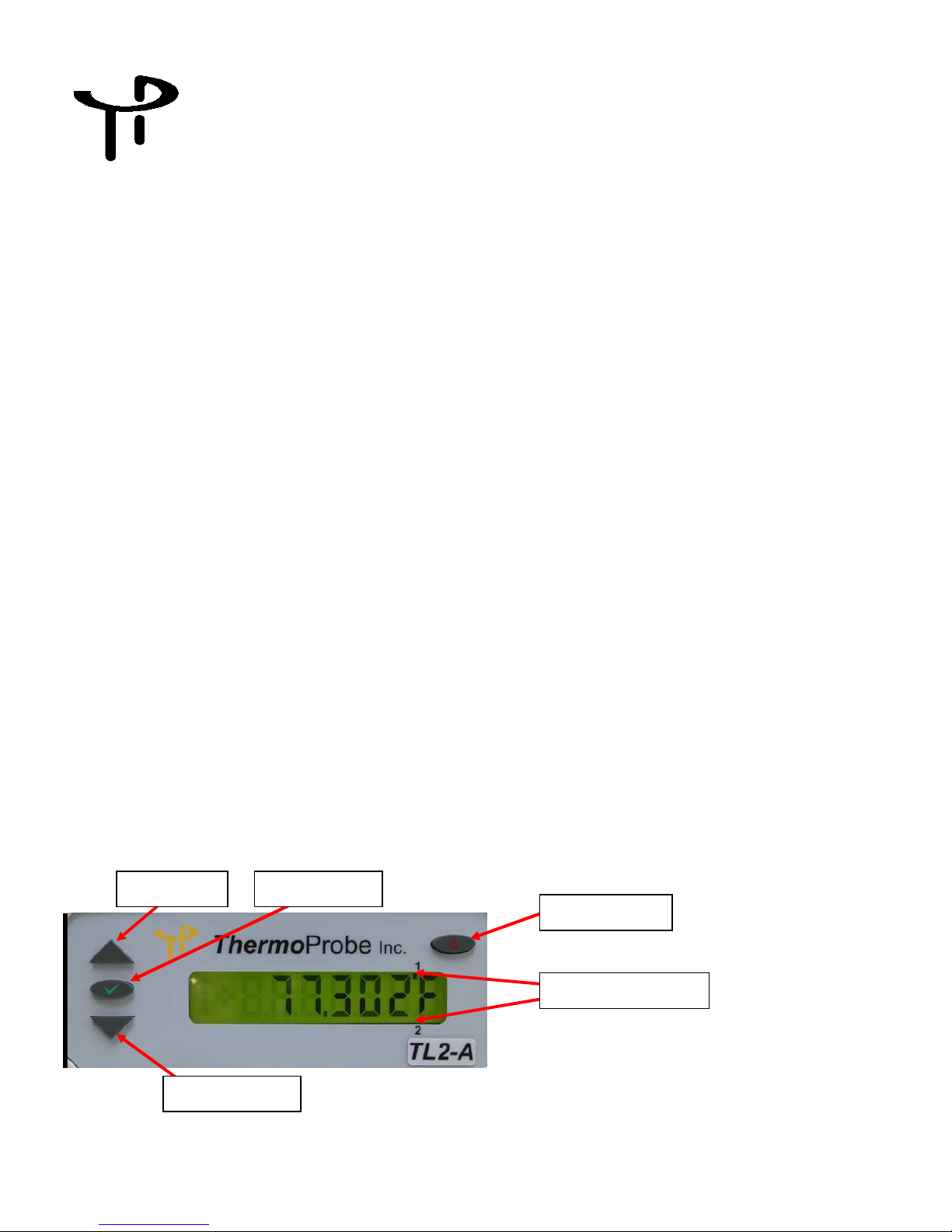
USER INTERFACE FRONT
Up Button
Select Button
Power Button
06/2015, JK
Down Button
Channel Indicators
1
Power Button (AC Unit) – Use the power button to save your settings (temperature units, display decimals,
zero adjustments, relay settings, etc.), and to place the TL2-A in ‘Standby’ mode. If you remove AC the power
without putting the TL2-A in Standby mode, the user settings will revert to the previous settings.
Select Button - Activates the user settings menu and selects menu items.
Up and Down Buttons - Selects the display for channel 1 and channel 2, navigates the menu (display
next/previous menu item). Also, adjusts the zero correction when in the Zero Adjust Mode.
Channel Indication – Marker indicates which channel is currently being displayed. (For active display and
menu functions)
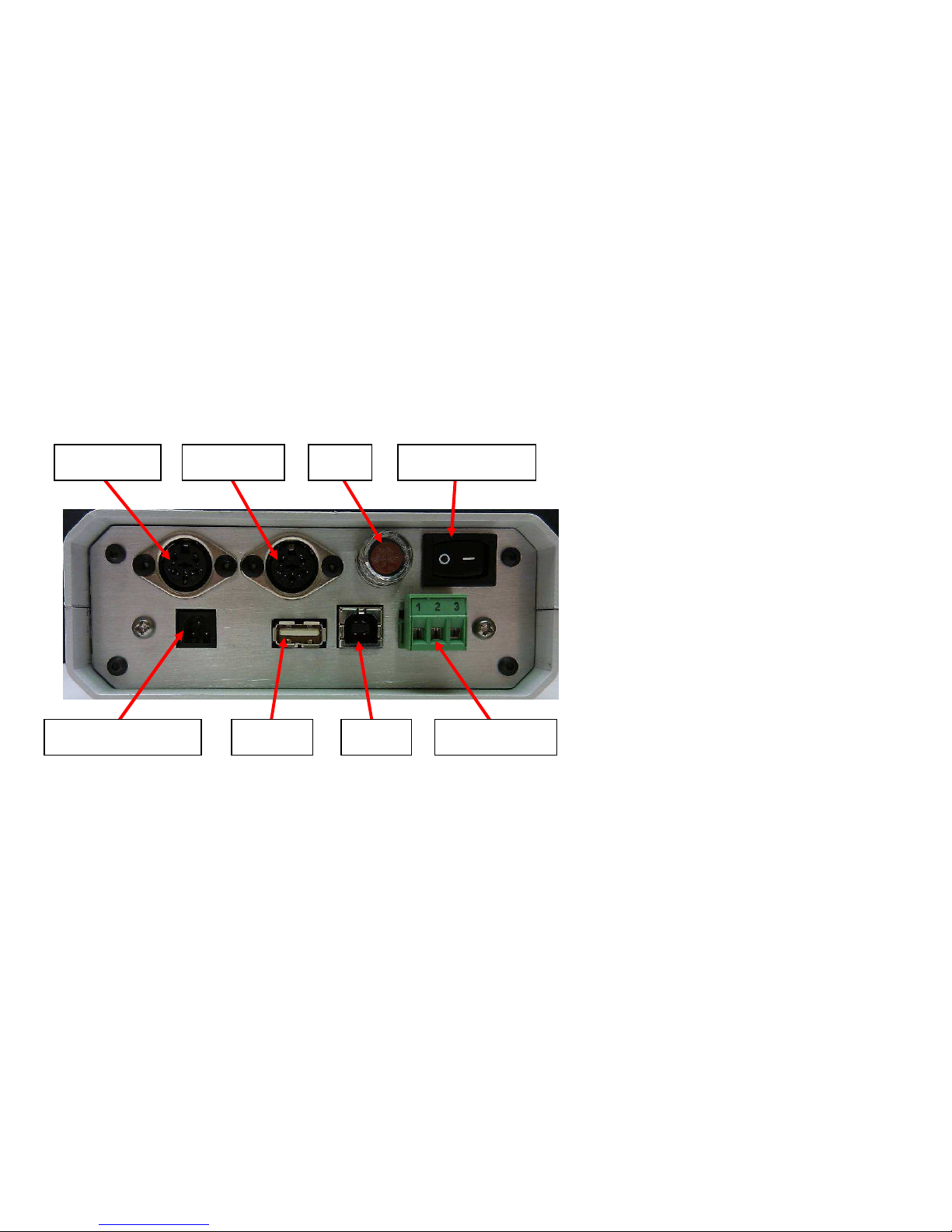
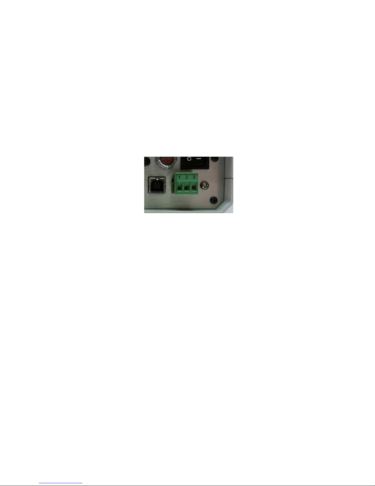
USER INTERFACE REAR
Channel 1 Channel 2
Fuse
On/Off Switch
Channel 1 &2 – Female sockets for probe connections.
USB1 - type ‘A’ socket for connecting flash USB devices
USB2 – type ‘B’ socket for PC interface cable
Relay Header – User configurable normally open or normally closed relay control
Power Switch – Used to turn units On and Off
USB1 USB2 AC power socket
Relay header
06/2015, JK
2
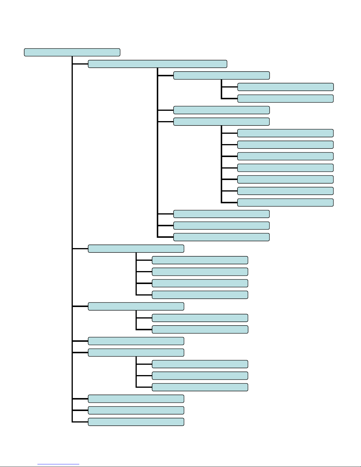
rELAY
Corr -
Displays Zero Correction
F (Fahrenheit)
AbS (Kelvin)
o (Ohms)
tHoU
(Thousandths)
UPdAtE
–
Communi
cation mode for coefficient update
donE -
Select to Exit Menu
10 sec
30 sec
60 sec
1 hr
PoLL
donE -
Select to Exit Menu
donE -
Select to Exit Menu
HASHoF
F–
Dis
ables Checksum
donE -
Select to Exit Menu
donE -
Select to Exit Menu
Interface Menu: (AC Powered Unit)
SELECT
rECord – Data logging setup & control
FLASH
StArt/StoP
PC
rAtE
1 sec
UnItS
dEC
L-A-H – Displays Low, Average & High readings
HASH on – Enables Checksum
C (Celsius)
Hds(Hundredths)
EnAbLe/dISAbLE
SEt
06/2015, JK
3
NOTES:
• All displayed values and changes are for the current selected channel only.
• To save settings, the Power Button must be pressed. This will set the unit to ‘Standby’.
• The low, average and high readings are cumulative from the time the TL2-A is powered on. They are
not saved when the TL2-A is shut down or put in standby and will re-start when the unit is turned on.
The low, average, and high readings will be displayed once the TL2-A's readings have stabilized (about
22 seconds.)
USB Flash Drive Logging (AC powered unit only):
1. Insert a flash drive into the USB1 type ‘A’ socket on the back of the TL2-A.
2. From the record menu, select ‘FLASH’ and ‘StArt’.
3. The TL2-A display will flash ‘ACCESS’ until the flash drive recording has started. (A ‘no DSC’ message will appear if the
flash drive is not detected).
4. The up/down arrow indicator will blink on the LCD display to indicate that logging is in process.
5. To stop the data logging, select ‘FL StoP’ from the menu. Wait for the ‘FL DonE’ message to display before removing the
flash drive from the TL2-A. (If the drive is removed before the logging has been stopped, the data will be lost.)
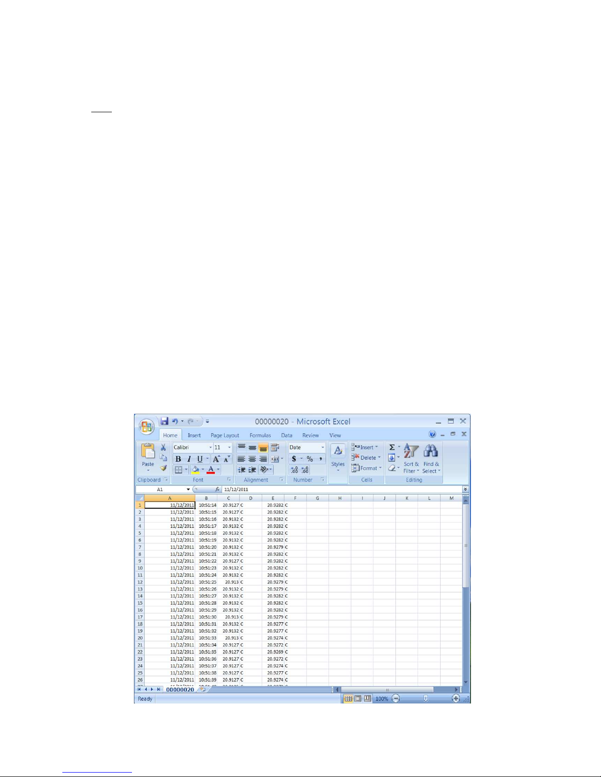
Once the flash drive data logging has been completed, the data can be opened on a standard PC.
Note: Each time the TL2-A records to the flash drive it will create a new file numbered sequentially higher than the previous file.
(ex: 0001.csv, 0002.csv, etc.)
1. Remove the flash drive from the TL2-A.
2. Insert the flash drive into a USB port on the PC.
3. Browse to the folder containing the flash drive contents.
4. The TL2-A data will be contained in a .csv file that can be opened with either Microsoft Excel or a text editor such as
Notepad.
5. The column format is as follows: Date, Time, Channel 1 reading, Channel 1 units, Channel 2 reading and Channel 2 units.
06/2015, JK
4
Polling Mode (AC powered unit only):
You can set the TL2-A to send data on command. This is useful for people who write data collection software that will request data
only when it is needed. To place the TL2-A in polling mode, select “PoLL” as the sample rate to be used under the recording section
of the TL2-A menu. (See Interface Menu Diagram) When the PC sends a question mark character (?) to the TL2-A, the TL2-A will
respond with the temperature. When the TL2-A is set to flash record mode, the polling feature will not work.
Temperature controlled Relay (AC powered unit only):
The TL2-A comes equipped with a switchable relay. This relay will toggle whenever the temperature crosses the set point threshold
set through the user menu. The provided screw-terminal header can be wired in two configurations:
• Terminals 1-2 are normally closed (NC) and will turn OFF (open) when the relay is set.
• Terminals 1-3 are normally open (NO) and will turn ON (close) when the relay is set.
Figure 1: Relay screw-terminal header
The relay function can be implemented from the user menu. For the relay function to be active, the user must select ‘EnAbLE’ from
the relay menu. Also from the relay menu, the temperature set point can be configured. (‘rELAY’ -> ‘SEt’) Use the Up & Down
buttons to select the desired setpoint. Use the select button to select each digit to modify. Ensure this setpoint is correct before
selecting the ‘EnAbLE’ function. The relay set point will remain the same regardless of the unit selection (C, F or K).
Once the relay has been toggled, it will remain in that state until the user disables it using the Select button. If desired, the user will
then need to re-enable the relay from the user menu.
06/2015, JK
5

Zero Correction
Over time, a sensor may experience a shift in temperature at different ranges of the instrument. Zero correction allows the user to
make an adjustment to the current channel temperature display that effectively corrects for this shift. This offset or ‘zero correction’
is applied to the entire effective range of the instrument. Each channel has its own zero correction.
NOTE: A zero correction made at a particular point may not correct the temperature at another point. It is recommended that the
instrument be fully calibrated annually to maintain acceptable temperature tolerances for the range of the instrument.
To view the zero correction for the current channel, select the “Corr” option from the menu.
To set a zero correction:
1. Use the function and arrow buttons to navigate to the “Corr” item in the menu. Press and hold the power button. While holding the
power button, press the function button until the "Adj" menu item appears. Release both buttons.
2. Press and release the function button again. The double arrows will flash indicating that you are in zero correction mode. Use the
up and down arrows to adjust the display temperature as desired. The adjustment will only apply to the channel on the display.
3. When you've adjusted the display, press and release the function button. Use the arrow buttons and the function button to save or
cancel the zero correction and exit zero correction mode.
4. To view the zero correction, use the function button and arrow buttons to navigate to the Corr menu item as before. This time,
press and release the function button. The display will show the zero correction for the selected channel and then return to
temperature display mode.
5. To save the zero correction, the Power Button must be pressed. This will set the unit to ‘Standby’.
PC Software setup:
There is a PC driver file that is needed to connect the TL2-A to your PC. We have included a disc with the
driver software for Windows XP, Windows Server 2003, Windows Vista, Windows Server 2008, Windows 7,
Windows Server 2008 R2. Other operating systems are supported and driver software is available.
Use the Windows Add Hardware Wizard and the driver files to set up a USB Com port to connect to the TL2A. Connect using HyperTerminal or other software that can connect interface with the selected Com port.
** The USB driver software web site is (http://www.ftdichip.com/Drivers/VCP.htm)
.Note These instructions are taken from a document that is available online from Future Technology Devices International.
(http://www.ftdichip.com/Support/Documents/AppNotes/AN_104_FTDI_Drivers_Installation_Guide_for_WindowsXP%28FT_000093%29
.pdf). Detailed technical information is available from that website. Technical assistance with installing the driver software is available from
ThermoProbe, Inc. Check http://thermoprobe.net/docs/index.html for the latest version of this document.
Instructions to install the TL2-A PC driver (Windows XP shown) The driver for the TL2-A PC (Future Technology Devices
International driver) installs a Virtual Com Port (VCP) on your PC. The steps to install this driver are:
1. Place the USB flash drive provided with your TL2-A in the USB port of the PC.
2. Connect the TL2-A to the PC with the provided USB cable.
3. Make sure the TL2-A is plugged into the wall with the AC power cord.
4. Make sure the TL2-A is powered on.
5. A Found New Hardware Wizard window should appear.
06/2015, JK
6
 Loading...