

Page 1
TL1 SERIES INSTRUCTIONS
INTRODUCTION
This manual describes the basic function, use and safety ins tructions for models TL1-A, TL1-W and TL1-R portable digital reference
thermometer instruments. These ThermoProbe instruments are intended for use in both haz a rdous (flammable) and no n-hazardous
areas under dry conditions at temperatures between -20 to 40°C. The instruments are not intended for use in permanent outdoor
installations and are not intended or tested for icing conditions.
may be exposed to excessive external stresses (e.g. vibration, heat, impact, etc.).
Additional means of protection should be used where the equipment
SAFETY INFORMATION BEFORE USE
ThermoProbe thermometers are designed for safe operation in hazardous locations (Potentially Flammable or Explosive). The user
must have a working knowledge of appropriate safety instructions.
a) Care should be taken upon installation of the instrument to prevent excessive heat exposure. The influence of radiated heat
may affect the safety of the instrument. See IEC 60079-14.
b) The TL1 thermometer stem should not be immersed past the plastic sensor mount (stainless fitting for TL1-W).
c) The instrument shall be checked concerning severe defects; check that instrument is complete, has good batteries, etc. If
necessary, check measurement accuracy. If any defects are found, the instrument should not be used until repairs have been
made.
d) Power source must be removed before performing any maintenance.
e) Exchange of components other than the batteries may compromise ATEX/IECEx certification and shall only be undertaken
by Thermoprobe or one of its qualified service providers. See also “Authorized Repair” section.
INTRINSIC SAFETY
Intrinsically safe equipment is defined as "equipment and wiring which is incapable of releasing sufficient electrical or thermal
energy under normal or abnormal conditions to cause ignition of a specific hazardous atmospheric mixture in its most easily ignited
concentration." (ISA-RP12.6) This is achieved by limiting the amount of power available to the electrical equipment in the hazardous
area to a level below that which will ignite the gases.
In order to have a fire or explosion; fuel, oxygen and a source of ignition must be present. An intrinsically safe system assumes the
fuel and oxygen is present in the atmosphere, but the system is designed so the electrical energy or thermal energy of a particular
instrument loop can never be great enough to cause ignition.
Safety Approvals for TL1 Thermometers:
II 2 G Ex ib IIC T4
09/2012, JK
Applicable Standards are: Agency or Safety Designation
IEC 60079-0:2007 Ed. 5 IECEx
IEC 60079-11:2006 Ed. 5 IECEx
EN 60079-0: 2009 Europe: ATEX
EN 60079-11:2007 Europe: ATEX
Page 2

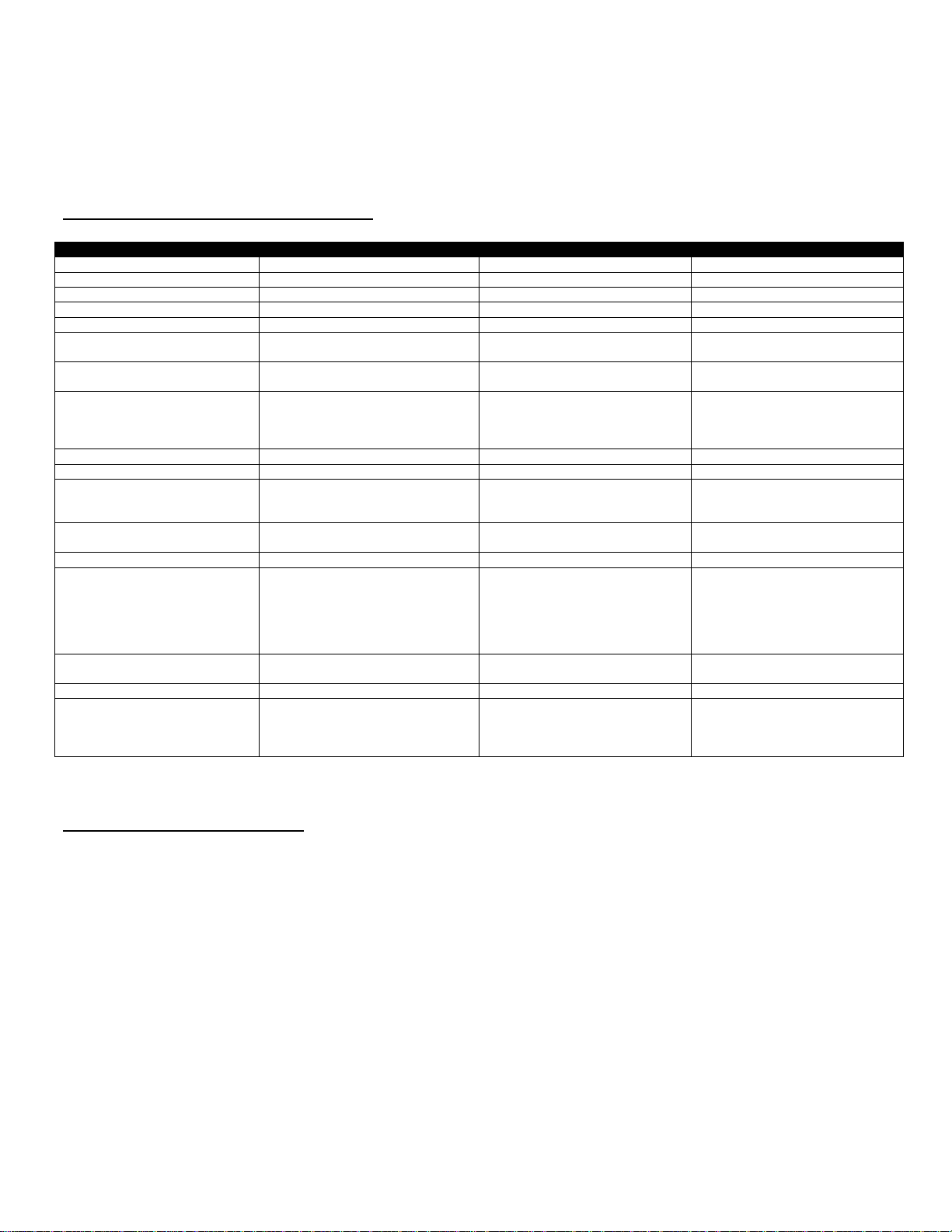
FEATURES & SPECIFICATIONS
09/2012, JK
Page 3

BATTERY REPLACEMENT
WARNING:
• Batteries must be changed in Non-hazardous area.
• Batteries must be of correct approved type.
• Batteries must be installed with correct polarity making sure the (+) end of the battery is aligned with (+) symbol embossed
in the battery case.
• New batteries must not be mixed with old batteries. Batteries must not be mixed with batteries of other manufacturers.
• Batteries must not be installed with polarity reversed where one cell could charge another cell.
a) Ensure the instrument is in a non-hazardous area.
b) Remove the 2 screws and back cover on the TL1 to access the batteries.
c) Install each new battery making sure the (+) end of the battery is aligned with (+) symbol embossed in the battery case.
d) For models with AAA batteries, the user must make certain that the rubber spacer remains in place after servicing the
batteries. This will ensure the batteries cannot shift during use.
e) Replace the back cover and 2 screws.
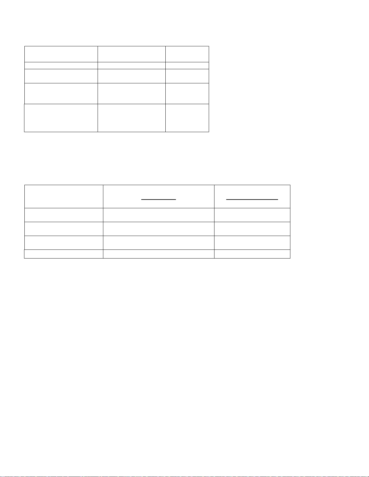
CERTIFIED Batteries are as follows:
Model Manufacturer Type Part Number
TL1-W, TL1-R Duracell AAA (LR03) Alkaline MN2400
TL1-W, TL1-R Panasonic AAA (LR03) Alkaline LR03XWA
TL1-W, TL1-R Gold Peak AAA (LR03) Alkaline GP24A
TL1-A Duracell CR2032 LiMnO
2
DL2032
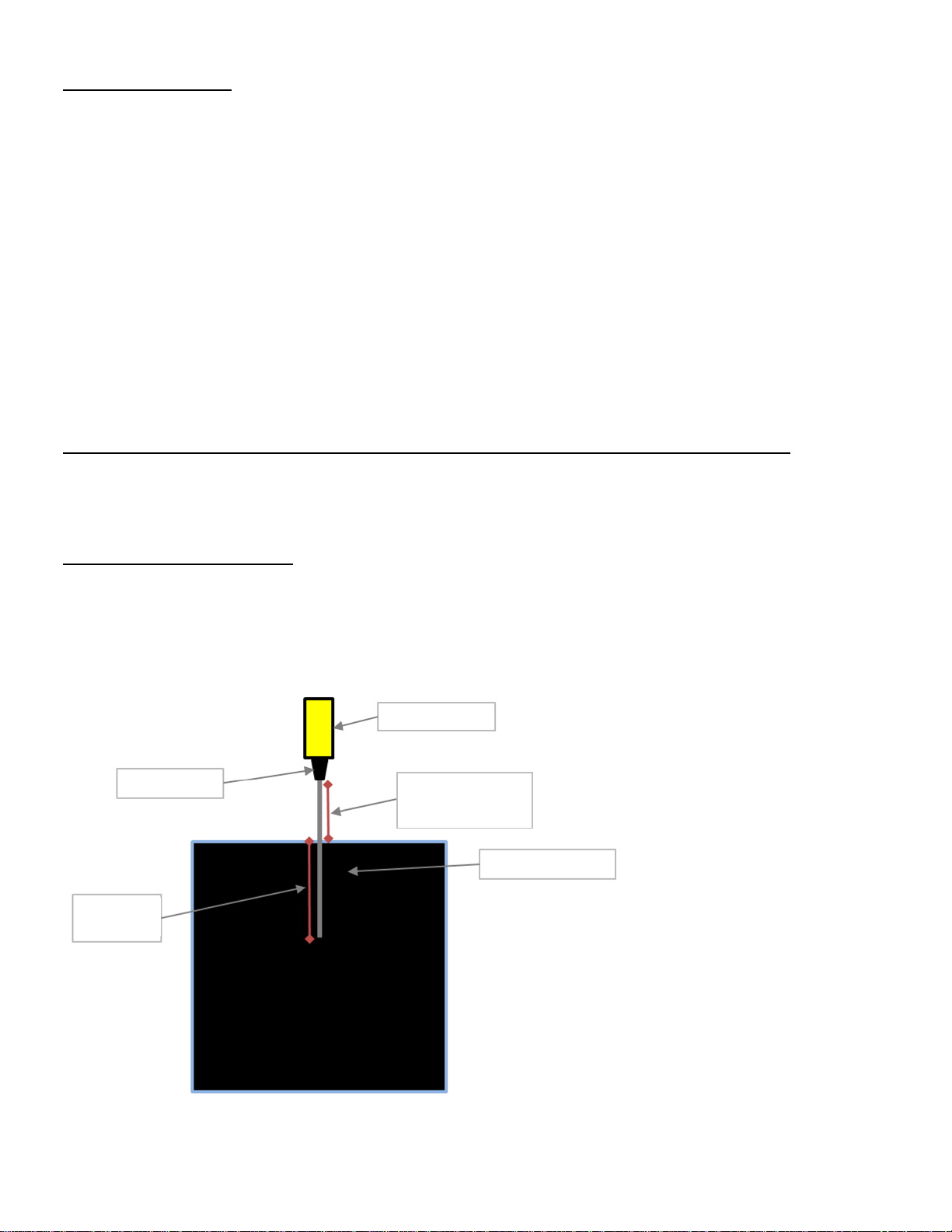
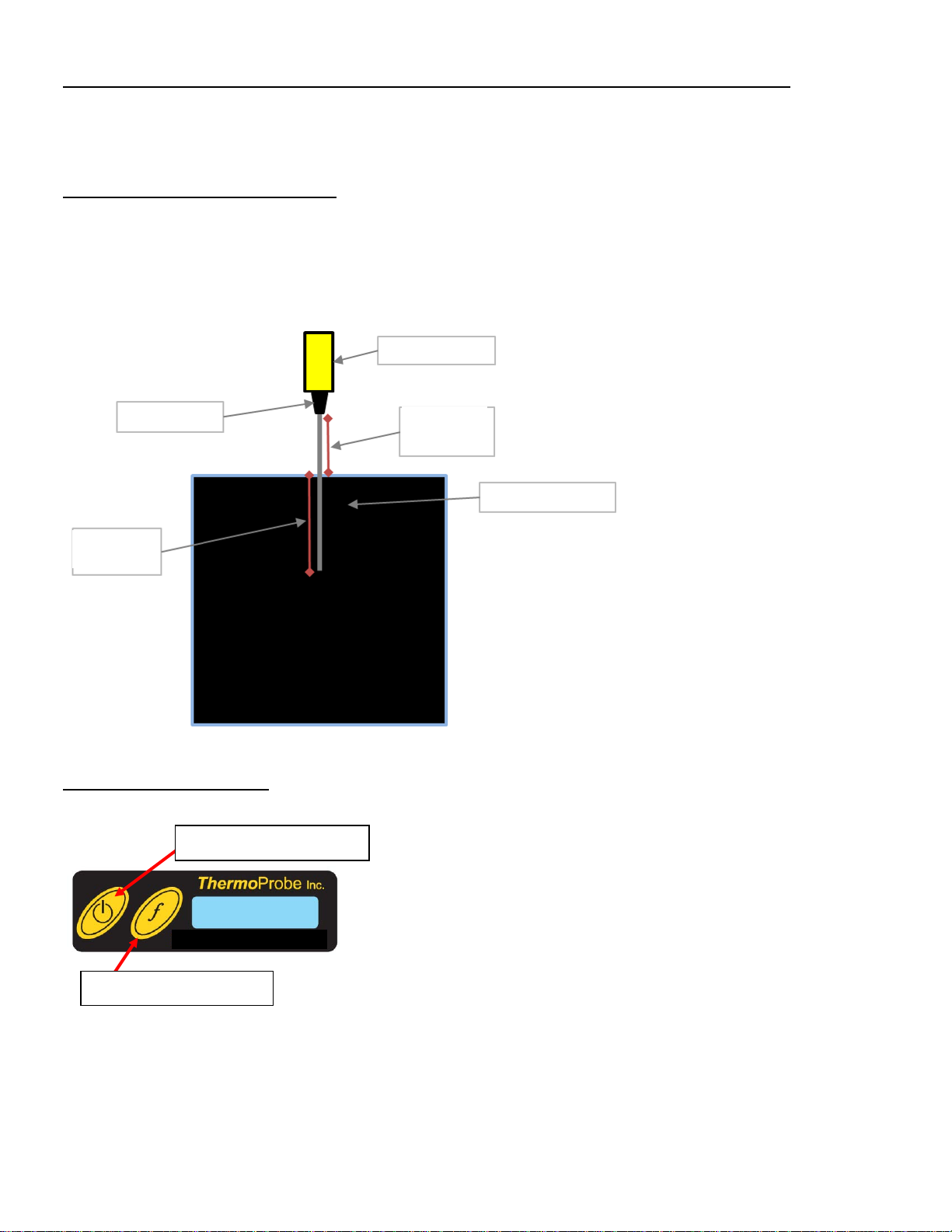
IMMERSION DEPTH
For best measurement results, a minimum immersion depth of 4 inches into the temperature source is recommended.
All TL1 models shall maintain a minimum separation between the sensor mount and temperature source to ensure that the
thermometer enclosure does not exceed 40°C.
Figure 1: TL1 immersion depth
09/2012, JK
Page 4

USER INTERFACE
One quick push
Power On
Hold 4 seconds
Enable Continuous
operation
*Hold and Release
Hold and Release
“Fn”
Displays Lowest, Average and Highest
readings
“C-F”
“dEC”
2
Changes unit resoluti on ( 0.1, 0.01 or 0.001)
“76.3 F” or “24.6 C”
“ZERo”
3
Displays Zero Correction
“0.005”
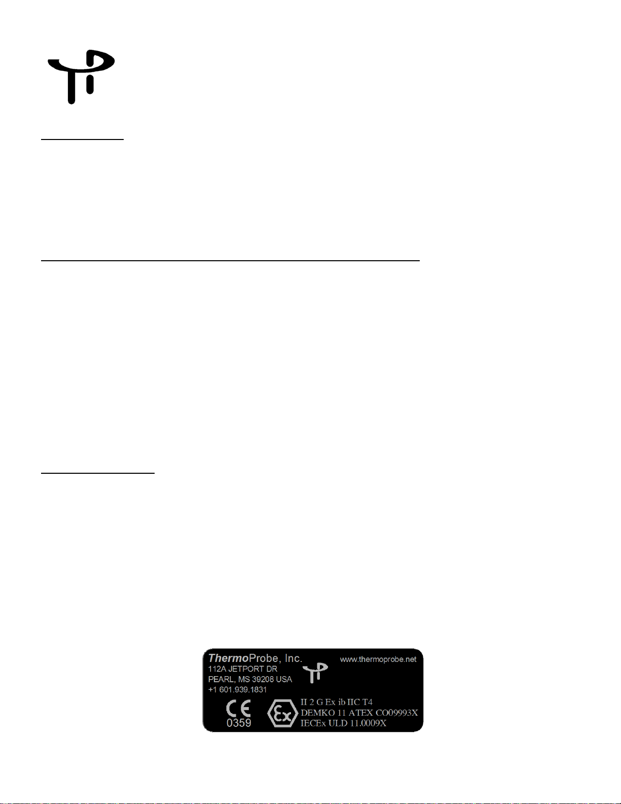
Power Button
Function Button
“Power” Button
Pressing the Power button once will turn on the device. The instrument will shut off automatically within 20 minutes.
Pressing and holding t he P o wer button for 4 seconds will disable the Auto-off feature. (‘Conn’ will flash momentarily to indicate
Continuous operation).
Pressing and holding t he P o wer button will and shut the instrument off and clear all logged and averaged readings.
Power button
when display reads “LigHt”
when display reads “oFF”
Operation Display
Turns on Backlight for 10
seconds
Power Off
(Clears Readings)
“Conn”
“LigHt”
“oFF”
* TL1-W Model only
Function “f” button
Press and Hold the Function Button “f” to display options in a menu format. When the desired function is displayed release the
button.
Hold and Release when the
display reads:
Notes:
1. As soon as the TL1 is turned on, the minimum, maximum and average data is continuously updated. Wait 20 seconds after
power-on to allow collection of readings before viewing minimum, average and maximum.
2. 0.001 Resolution available on TL1-R models only.
3. Zero Correction Available on TL1-R models only.
Function (“f”) Example on Display
78.61 L, 78.70 A, 78.93 H
Changes units “76.3 F” or “24.6 C”
09/2012, JK
Page 5

Display Arrows
TThheerrmmooPPrroobbee,, IInncc..
The Arrows on the left side of the screen will show you at a glance as to whether the reading is increasing, decreasing or has
stabilized. Intuitively the Up Arrow symbolizes an increasing temperature, the Down Arrow a decreasing temperature and no arrows
a stabilized status.
Battery Check
When the voltage of the batteries is low, the device will indicate “Lo bAtt” on the display before resuming normal display functions.
Do not attempt to calibrate the instrument if the “Lo bAtt” has been displayed since the new calibration values may not be properly
stored to memory.
Error Codes
ErrHI indicates an over range reading, meaning the temperature at the sensor has risen above the specified limit of the unit. This also
may indicate an open-circuit condition in the unit which may require repair.
ErrLO indicates a below range reading, meaning the temperature at the sensor has dropped below the specified limit of the unit. This
also may indicate a short-circuit condition in the unit which may require repair.
ZERO CORRECTION MODE: (TL1-R Model Only)
Note: Corrections made will offset temperature over the entire range of the device.
1. Simultaneously press the function and on/off button. Release when ‘AdJ’ is displayed to enter zero correction mode.
2. While in zero correction mode, press and hold the power button to select ‘UP’, ‘dn’, ‘SAVE’, ‘no SAVE’ or ‘CAnC’.
3. If ‘UP’ is selected, the temperature can be adjusted up by pressing the function button.
4. If ‘dn’ is selected, the temperature can be adjusted down by pressing the function button.
5. If ‘CAnC’ (cancel) is selected, the instrument is still in zero correction mode and further adjustments can be made.
6. To save and exit after corrections has been made, hold the power button until ‘SAVE’ is displayed.
7. To exit without any zero correction changes, hold the power button until ‘no SAVE’ is displayed.
8. The instrument will return to normal operation.
9. To momentarily view the zero correction from the normal menu, hold the function button and release when ‘ZERo’ is
displayed.
CALIBRATION
Calibration service is available from ThermoProbe, Inc. and authorized distributors. Contact ThermoProbe, Inc. for requirements if
onsite calibration is desired.
AUTHORIZED REPAIR
It is recommended that service beyond the scope of this manual be performed by ThermoProbe, Inc. or one of its authorized
distributors.
112A JETPORT DR.
PEARL, MS 39208
Tel: +1 601.939.1831
Fax: +1 601.355.1831
sales@thermoprobe.net
www.thermoprobe.net
09/2012, JK
Page 6

DECLARATION OF CONFORMITY
Apparatus Identification ThermoProbe Inc. Models TP7-C, TP9, TL1-A, TL1-W and TL1-R
Portable Digital Thermometers
Apparatus Classification Measurement Equipment
Statement of Conformity
Based on sample product test results using approp ri ate standards (Industrial environment), and in
accordance with the following EC Directiv es, ThermoProbe Inc. hereby declares the ThermoProbe Inc.
Models TP7-C, TP9, TL1-A, TL1-W and TL1-R to be in conformity with:
EC ATEX Directive 94/9/EC, Equipment or Protective System
intended for use in Potentially Explosive Atmospheres.
Sample Product Testing for ATEX
Tested By DEMKO
Standards Used EN 60079-0: 2009
EN 60079-11: 2007
Report ID
Manufacturer ThermoProbe Inc.
112A Jeport Dr.
Pearl, MS 39208
President
11K04891
Luke Bartkiewicz
10/5/12 JK
Page 7

Série TL1 - INSTRUCTIONS
MISE EN GARDE – UTILISER
INSTRUCTIONS.
INTRODUCTION
Ce manuel décrit les fonctions de base et les instructions pour la sécurité et l'utilisation des thermomètres numériques de référence
portables TL1-A, TL1-W et TL1-R. Ces instruments ThermoProbe sont conçus pour être ut ilisés aussi bien dans des e nvironnements
dangereux (inflammables) que des environnements sans danger, secs, à des températures entre -20 et 40°C. Ces instruments ne
doivent pas être utilisés dans des installations en plein air permanentes et ne sont ni conçus ni testés pour le gel. Lorsque l'équipement
risque d'être exposé à des contraintes extérieures excessives (vibrations, chaleur, chocs, etc.) il convient d'utiliser des protections
supplémentaires.
CONSIGNES DE SÉCURITÉ AVANT UTILISATION
Les thermomètres ThermoProbe sont conçus pour être utilisés en toute sécurité dans des environnements dangereux (potentiellement inflammables ou explosifs). L'utilisateur doit avoir pris connaissance des consignes de sécurité appropriées.
a) Il convient d'installer l'instrument avec soin pour éviter qu'il ne soit exposé à une chaleur excessive. L'influence de la
chaleur radiante risque d'affecter la sécurité de l'instrument. Voir IEC 60079-14.
b) La tige du thermomètre TL1 ne doit pas être immergée au delà de l'embase du capteur plastique (montage inoxydable pour
le TL1-W)
c) L'instrument doit être vérifié pour éviter tout défaut grave ; s’assurer que l'instrument est complet, que ses batteries sont
chargées, etc. Si besoin, vérifier sa précision de mesure. En cas de défaut, ne pas utiliser l'instrum e nt jusqu'à ce qu'il soit
réparé.
d) L'alimentation doit être enlevée avant toute opération de maintenance.
e) L'échange de composants autres que les piles risque de compromettre la certification ATEX/IECEx et ne doit être effectué
que par Thermoprobe ou l'un de ses fournisseurs de service qualifiés. Consulter aussi la section « Réparations autorisées ».
SÉCURITÉ INTRINSÈQUE
Un équipement intrinsèquement sûr est défini comme « un équipement et câblage incapables de dé gager une énergie éle c trique ou
thermique suffisante dans des conditions normales ou anormales, pouvant provoquer l'inflammation d'un mélange atmosphérique
spécifique dangereux dans sa concentration la plus aisément inflammable ». (ISA-RP12.6). Cette sécurité est assurée en limitant le
courant fourni à l'équipement électrique dans une zone dangereuse à un niveau inférieur au point d'inflammation des gaz.
Pour provoquer un ince ndi e ou une explosion, du carburant, de l'oxygène e t une s ource d'allumage doivent être présents. Un système
intrinsèquement sûr présume que le carburant et l'oxygène sont présents dans l'atmosphère, mais le système est conçu de façon à ce
que l'énergie électrique (ou l'énergie thermique) d'une boucle d'un instrument particulier ne soit jamais suffisante pour causer
l'allumage.
Sécurité approuvée pour thermomètres TL1 :
II 2 G Ex ib IIC T4
09/2012, JK
UNIQUEMENT LES PILES
SPECIFIEES DANS LES
Normes applicables : Désignation de l'agence ou de la sécurité
IEC 60079-0:2007 Ed. 5 IECEx
IEC 60079-11:2006 Ed. 5 IECEx
Page 8

EN 60079-0: 2009 Europe: ATEX
Spécifications
TL1-A
TL1-W
TL1-R
Portable
OUI
OUI
OUI
Traçable NIST
OUI
OUI
OUI
Affichage à rétroéclairage
NON
OUI
NON
Résolution de l'affichage
0.01
0.01
0.001
Durée de vie des piles (Heures)
95
350
200
Certifié sécurité intrinsèque
ATEX & IECEx (Ex ib IIC T4)
ATEX & IECEx (Ex ib IIC T4)
ATEX & IECEx (Ex ib IIC T4)
Gamme de température standard
14°F à 320°F (-10°C à 160°C)
14°F à 320°F (-10°C à 160°C)
22°F à 320°F (-30°C à 160°C)
4 Points Standard:
4 Points Standard:
5 Points Standard:
(148.9°C)
Tolérance
0.1°F (0.06°C)
0.1°F (0.06°C)
0.07°F (0.04°C)
Incertitude
0.03°F (0.017°C)
0.03°F (0.017°C)
0.03°F (0.017°C)
Piles
Duracell DL2032 (IEC CR2032)
Duracell MN2400 Alkaline AAA
Gold Peak GP24A Alkaline AAA
Duracell MN2400 Alkaline AAA
Gold Peak GP24A Alkaline AAA
Gamme ambiante de température
de fonctionnement
-4° à 104°F (-20° à 40°C)
-4° à 104°F (-20° à 40°C)
-4° à 104°F (-20° à 40°C)
Temps de réponse température
8 secondes dans l’eau
8 secondes dans l’eau
19 secondes dans l’eau
Capteur
Tube du capteur de 1/4" diamètre en
3/16", classe 100 Ohms
Tube du capteur de 1/4" diamètre
fine de 3/16", classe 100 Ohms
Tube du capteur de 1/4" diamètre
fil de platine enroulé 200 Ohms
Boîtier
Boîtier standard en aluminium
anodisé
Boîtier durci en aluminium anodisé,
montage horizontal
Boîtier standard en aluminium
anodisé
Poids (avec capteur 8 pouces)
3.6 oz (102 g)
9.5 oz (269.3 g)
4.6 oz (130.4 g)
Caractéristiques de
Arrêt automatique ou
Arrêt automatique ou
rétroéclairage
Arrêt automatique ou
d’affichage en millièmes
EN 60079-11:2007 Europe: ATEX
CARACTÉRISTIQUES & SPÉCIFICATIONS
Étalonnage (Voir remarque)
fonctionnement
32°F (0°C), 120°F (48.9°C), 200°F
(93.3°C), 300°F (148.9°C)
Bouton 3V Lithium Manganese
acier inoxydable avec pointe fine de
fonctionnement continu, lectures
min, max et moyennes, affichage en
degrés C ou F
32°F (0°C), 120°F (48.9°C), 200°F
(93.3°C), 300°F (148.9°C)
Panasonic LR03XWA Alkaline AAA
en acier inoxydable avec pointe
fonctionnement continu, lectures
min, max et moyennes, affichage
en degrés C ou F, affichage à
-4°F (-20°C), 32°F (0°C), 120°F
(48.9°C), 200°F (93.3°C), 300°F
Panasonic LR03XWA Alkaline AAA
en acier inoxydable, sonde RTD à
fonctionnement continu, lectures
min, max et moyennes, affichage
en degrés C ou F, résolution
Remarque : Gammes de températures c al ibrées personnalisées supplémentaires disponibles de -40°F à 555°F (-40°C à 290°C) en
fonction de la disponibilité du capteur
REMPLACEMENT DES PILES
MISE EN GARDE :
• Les piles doivent être changées dans des endroits sûrs.
• Le type des piles doit être approuvé.
• Les piles doivent être installées selon des polarités correctes, en s'assurant que le pôle (+) de la pile est aligné avec le
symbole (+) de l'enceinte des piles.
• Ne pas mélanger des piles neuves avec d'anciennes piles. Ne pas utiliser des piles de marques différentes.
• Ne pas installer les piles en inversant les polarités, ce qui provoquerait le chargement d'une pile par l'autre.
a) S'assurer que l'instrument se trouve dans un endroit sûr.
b) Enlever les 2 vis et le couvercle du fond du TL 1 pour accéder aux piles.
c) Installer chaque pile en s'assurant que le pôle (+) de la pile est aligné avec le symbole (+) de l'enceinte des piles.
d) Pour les modèles utilisant des piles AAA, l'utilisateur doit s'assurer que le joint en caoutchouc reste bien en place après avoir
changé les piles. Cela empêchera les piles de bouger.
e) Refermer le couvercle du fond et remettre les 2 vis.
Piles CERTIFIÉES :
Modèle Fabricant Type Numéro
TL1-W, TL1-R Duracell AAA (LR03) Alkaline MN2400
TL1-W, TL1-R Panasonic AAA (LR03) Alkaline LR03XWA
TL1-W, TL1-R Gold Peak AAA (LR03) Alkaline GP24A
TL1-A Duracell CR2032 LiMnO
2
DL2032
09/2012, JK
Page 9

Bouton de mise sous tension
Bouton Fonction
Thermomètre TL
Embase du capteur
Distance
minimale de
2" (5 cm)
Source de température
Profondeur
d'immersion
Thermomètre TL1-A
PROFONDEUR D’IMMERSION
Pour obtenir de meilleurs résultats, il est recommandé d'immerger le thermomètre dans la source de température à une profondeur
minimale de 4 pouces (10 cm).
Tous les modèles TL 1 doivent maintenir une distance minimum entre l'embase du capteur et la source de température, afin que le
boîtier du thermomè tre ne dépasse pas 40°C.
Figure 1 : Profondeur d'immersion du TL 1
INTERFACE UTILISATEUR
Bouton de mise sous tension
Appuyer une fois sur le bouton de mise sous tension pour mettre l'appareil en marche. L'instrument s'arrêtera automatiquement au
bout de 20 minutes.
Appuyer sur le bouton de mise sous tension et le garder appuyé pendant 4 sec ondes pour désactiver la fonction d'arrêt automatique
(auto-off). (‘Conn’ clignotera quelques instants pour indiquer que l'instrument continue à fonctionner).
Presser le bouton de mise sous tension et le garder appuyé pour arrêter complètement l'instrument et effacer toutes les mesures
enregistrées et calculées.
09/2012, JK
Page 10

Une pression rapide
Met sous tension
Maintenir la pression 4 secondes
Permet un fonctionnement continu
Conn
* Maintenir la pression et relâcher
quand l'affichage indique “LigHt”
Allume le rétroéclairage pendant
10 secondes
Maintenir la pression et relâcher
Fn
Affiche les mesures les plus hautes,
les plus basses et la moyenne
C-F
2
Change la résolution de l'unité
(0.1, 0.01 ou 0.001)
ZERo
3
Affiche Correction du zéro
0.005
Bouton de mise sous tension
quand l'affichage indique “oFF”
Fonctionnement Affichage
LigHt
Arrête l’alimentation
(Efface les mesures)
oFF
* Modèle TL1-W uniquement
Bouton Fonction « f »
Presser la touche Fonction « f » et la garder appuyée pour afficher les options sous forme de menu. Relâcher le bouton lorsque la
fonction souhaitée s'affiche.
Maintenir la pression et relâcher
quand l'affichage indique :
dEC
Remarques :
1. Dès que le thermomètre TL1 est activé, les données minimum, maximum et moyennes sont continuellement mises à jour.
Attendre 20 secondes après l'allumage pour relever des mesures avant de lire les données minimum, moye nnes et maximum.
2. Résolution 0.001 disponible sur les modèles TL1-R uniquement.
3. Correction du zéro disponible sur les modèles TL1-R uniquement.
Fonction (« f ») Exemple affiché
78.61 L, 78.70 A, 78.93 H
Change les unités 76.3 F ou 24.6 C
76.3 F ou 24.6 C
Flèches d'affichage
Les flèches sur le côté gauche de l'écran indiquent immédiatement si les mesures augmentent, diminuent ou restent stables.
De manière intuitive, la flèche vers le haut symbolise une température qui augmente, la flèche vers le bas une température qui
diminue, et l'absence de flèche indique une température stable.
Vérification des piles
Lorsque la tension des piles est faible, l'affichage indique « Lo bAtt » avant de recommencer à afficher des fonctions normales.
Ne pas tenter de recalibrer l'instrument quand l'affichage indique « Lo bAtt » car les nouvelles valeurs de calibration risquent de ne
pas être enregistrées correctement dans la mémoire.
Codes d’erreur
ErrHI indique des valeurs trop hautes, c'est-à-dire que la température relevée par le capteur a dépassé la gamme autorisée pour cette
unité. Cela peut également indiquer un circuit ouvert qui doit être réparé.
ErrLO indique des valeu r s t r op basses, c'est-à-dire que la température relevée par le capteur est tombée en dessous de la gamme
autorisée pour cette unité. Cela peut également indiquer un court-circuit qui doit être réparé.
09/2012, JK
Page 11

MODE CORRECTION DU ZÉRO : (Modèle TL1-R uniquement)
ThermoProbe, Inc.
Remarque : Les corrections effectuées vont décaler les températures sur toute la gamme de l'appareil.
1. Appuyer simultanément sur le bouton Fonction et le bouton de mise sous tension. Les relâcher lorsque l'affichage indique «
AdJ » pour entrer en mode Correction du zéro.
2. Pendant que vous êtes en mode Correction du zéro, appuyer et maintenir la pression sur le bouton de mise sous tension afin
de sélectionner « UP », « dn », « SAVE », « no SAVE » ou « CanC ».
3. Si « UP » est sélectionné, la température peut être ajustée vers le haut en appuyant sur le bouton Fonction.
4. Si « dn » est sélectionné, la température peut être ajustée vers le bas en appuyant sur le bouton Fonction.
5. Si « CanC » (annuler) est sélectionné, l'instrument est toujours en mode Correction du zéro et vous pouvez effectuer d'autres
ajustements.
6. Pour enregistrer et sortir après avoir fait des corrections, maintenir la pression sur le bouton de mise sous tension jusqu'à ce
que l'affichage indiq ue « SAVE ».
7. Pour sortir sans aucune correction du zéro, maintenir la pression sur le bouton de mise sous tension jusqu'à ce que
l'affichage indique « no SAVE ».
8. L'instrument reviendra à un mode de fonctionnement normal.
9. Pour visualiser occasionnellement la correction du zéro à partir du menu normal, maintenir le bouton Fonction et le relâcher
lorsque l'affichage indique « ZERo ».
ÉTALONNAGE
Des services d'étalonnage sont disponibles chez ThermoProbe, Inc. et les distributeurs autorisés. Contacter ThermoProbe, Inc. au
sujet des exigences requises pour l'étalonnage dans vos locaux.
RÉPARATIONS AUTORISÉES
Recommandation : Tout service non décrit dans ce manuel doit être effectué par la société ThermoProbe, Inc. ou l'un de ses
distributeurs autorisés.
112A JETPORT DR.
PEARL, MS 39208
Tél : +1 601.939.1831
Fax : +1 601.355.1831
sales@thermoprobe.net
www.thermoprobe.net
09/2012, JK
Page 12

DÉCLARATION DE CONFORMITÉ
Identification de l'appareil ThermoProbe Inc. Modèles TP7-C, TP9, TL1-A, TL1-W et
TL1-R Thermomètres numériques portables
Classification de l'appareil
Déclaration de conformité
Au vu des résultats de tests effectués sur un produit type en respectant les normes adéquates
(Environnement industriel) et conformément aux Directives CE, ThermoProbe Inc. déclare par la
présente que les modèles TP7-C, TP9, TL1-A, TL1-W et TL1-R ThermoProbe Inc. sont conformes à la :
Directive 94/9/EC ATEX CE, Matériel ou système de protection
à utiliser en présence d'atmosphères potentiellement explosives.
Test de produit type pour atmosphère explosive (ATEX)
Testé par
Normes utilisées
EN 60079-11 : 2007
ID de rapport
Fabricant
112A Jeport Dr.
Pearl, MS 39208
Président
DEMKO
EN 60079-0 : 2009
11K04891
ThermoProbe Inc.
Instrument de mesure
Luke Bartkiewicz
5/10/12 JK
Page 13

INSTRUCCIONES PARA LA SERIE TL1
Advertencia – Use únicamente
INTRODUCCIÓN
Este manual describe las instrucciones básicas de las funciones, el uso y la seguridad para los modelos TL1-A, TL1-W y TL1-R de
los instrumentos termométricos de referencia digitales portátiles. Estos instrumentos ThermoProbe han sido diseñados para su uso
tanto en áreas peligrosas (inflamables) como no peligrosas, en condiciones secas y a temperaturas entre -20 y 40°C. Estos
instrumentos no han sido diseñados para su uso en instalaciones permanentes al aire libre ni han sido diseñados ni puestos a prueba
para condiciones de hielo.
externas exigentes (por ejemplo, vibración, calor, impactos, etc.).
Deberán usarse medios de protección adicionales allá donde el equipo pueda estar expuesto a condiciones
INFORMACIÓN DE SEGURIDAD ANTES DEL USO
Los termómetros ThermoProbe han sido diseñados para una operación segura en emplazamientos peligrosos (potencialmente
inflamables o explosivos). El usuario deberá tener un conocim i e nto práctico de las instrucciones de seguridad apropiadas.
a) Deberán tomarse precauciones al instalar el instrumento para evitar una excesiva exposición al calor. La influencia del calor
irradiado puede afectar la seguridad del instrumento. Consulte IEC 60079-14.
b) El vástago del termómetro TL1 no debe sumergirse más allá de la montura del sensor de plástico (accesorio de acero
inoxidable para el modelo TL1-W).
c) Deberá revisarse el instrumento para detectar defectos graves, comprobarse que el instrumento esté completo, que tenga las
pilas en condiciones, etc. Si es necesario, compruebe la fiabilidad de las mediciones. Si se detecta algún defecto, no deberá
usarse el instrumento hasta que se repare.
d) Debe quitarse la fuente de energía antes de proceder a la realización de reparación o mantenimiento.
e) El reemplazo de componentes que no sean las pilas puede poner en compromiso la certificación ATEX/IECEx y solo podrá
ser llevado a cabo por Thermoprobe o uno de sus proveedores de servicio calificados. Véase también la sección “Reparación
autorizada”.
SEGURIDAD INTRÍNSECA
Se dice que un equipo tiene seguridad intrínseca si "el equipo y el cableado no tienen capacidad para liberar suficiente energía
eléctrica o térmica, en condiciones normales o anormales, para provocar la ignición de una mezcla atmosférica específica peligrosa
en su concentración de ignición más probable". (ISA-RP12.6) Esto se consigue limitando la cantidad de energía disponible para el
equipo eléctrico en el área peligrosa hasta un nivel inferior al que provocaría la ignición de los gases.
Para que pueda darse un inc endio o una explosión debe ha ber presentes combus tible, oxígeno y una fuent e de ignición. Un sistema
que tiene seguridad intrínseca asume que el combustible y el oxígeno están presentes en la atmósfera, pero el sistema está diseñado
de forma que la energía eléctrica o térmica del circuito del instrumento en particul ar nunca pueda ser lo suficientemente grande para
provocar la ignición.
Aprobaciones de seguridad para los Termómetros TL1:
II 2 G Ex ib IIC T4
09/2012, JK
las pilas que se especifican en
las instrucciones del usuario.
Page 14
Los estándares aplicables son: Agencia o Designación de Seguridad
Especificaciones
TL1-A
TL1-W
TL1-R
Portátil
SÍ
SÍ
SÍ
Trazabilidad NIST
SÍ
SÍ
SÍ
Pantalla retroiluminada
NO
SÍ
NO
Resolución de pantalla
0.01
0.01
0.001
Vida útil de la pila (Horas)
95
350
200
Certificado intrínsecamente
seguro
ATEX & IECEx (Ex ib IIC T4)
ATEX & IECEx (Ex ib IIC T4)
ATEX & IECEx (Ex ib IIC T4)
Variación de temperatura
estándar
14°F a 320°F (-10°C a 160°C)
14°F a 320°F (-10°C a 160°C)
22°F a 320°F (-30°C a 160°C)
4 Puntos Estándar:
4 Puntos Estándar:
5 Puntos Estándar:
(148.9°C)
Tolerancia
0.1°F (0.06°C)
0.1°F (0.06°C)
0.07°F (0.04°C)
Incertidumbre
0.03°F (0.017°C)
0.03°F (0.017°C)
0.03°F (0.017°C)
Pilas
Duracell DL2032 (IEC CR2032)
Duracell MN2400 Alcalina AAA
Gold Peak GP24A Alcalina AAA
Duracell MN2400 Alcalina AAA
Gold Peak GP24A Alcalina AAA
Variación de ambiente de
operación
-4° a 104°F (-20° a 40°C)
-4° a 104°F (-20° a 40°C)
-4° a 104°F (-20° a 40°C)
Respuesta a la temperatura
8 segundos en baño de agua
8 segundos en baño de agua
19 segundos en baño de agua
Sensor
Tubo de sensor de acero inoxidable
Tubo de sensor de acero
Tubo de sensor de acero
enrollado
Construcción de cubierta
Cubierta de aluminio anodizado
estándar
Cubierta de aluminio anodizado
extra resistente, montaje horizontal
Cubierta de aluminio anodizado
estándar
Peso (con sensor de 8 pulg)
3.6 oz (102 g)
9.5 oz (269.3 g)
4.6 oz (130.4 g)
Funciones operativas
Auto-apagado u operación continua,
Auto-apagado u operación
retroiluminación
Auto-apagado u operación
Resolución milesimal de pantalla
IEC 60079-0:2007 Ed. 5 IECEx
IEC 60079-11:2006 Ed. 5 IECEx
EN 60079-0: 2009 Europa: ATEX
EN 60079-11:2007 Europa: ATEX
FUNCIONES Y ESPECIFICACIONES
Calibración (ver nota)
32°F (0°C), 120°F (48.9°C), 200°F
(93.3°C), 300°F (148.9°C)
Tamaño botón 3V Litio Manganeso
de 1/4 pulg (6.4 mm) de diámetro
con punta reducida de 3/16 pulg
(4.8 mm), Clase 100 Ohmios
lecturas Mín, Máx y Promedio,
Lectura en C o F
32°F (0°C), 120°F (48.9°C), 200°F
(93.3°C), 300°F (148.9°C)
Panasonic LR03XWA Alcalina AAA
inoxidable de 1/4 pulg (6.4 mm) de
diámetro con punta reducida de
3/16 pulg (4.8 mm), Clase
100 Ohmios
continua, lecturas Mín, Máx y
Promedio, Lectura en C o F,
-4°F (-20°C), 32°F (0°C), 120°F
(48.9°C), 200°F (93.3°C), 300°F
Panasonic LR03XWA Alcalina AAA
inoxidable de 1/4 pulg (6.4 mm) de
diámetro, 200 Ohmios Detector de
temperatura de resistencia (RTD,
siglas en inglés) de platino
continua, lecturas Mín, Máx y
Promedio, Lectura en C o F,
Nota: Variaciones adicionales de t em peratura calibradas a la medida disponibles de -40°F a 555°F (-40°C a 290°C) en base a
disponibilidad de sensores
REEMPLAZO DE LAS PILAS
ADVERTENCIA:
• Las pilas deben cambiarse en un área no peligrosa.
• Las pilas deberán ser del tipo aprobado correspondiente.
• Las pilas deberán instalarse con la polaridad correcta, asegurándose de que el polo (+) de la pila está alineado con el símbolo
(+) estampado en el receptáculo de la pilas.
• No deberán mezclarse pilas nuevas con pilas viejas. Las pilas no deberán mezclarse con pilas de otros fabricantes.
• No deberán instalarse pilas con la polaridad invertida donde una pila pueda cargar a otra pila.
a) Verifique que el instrumento se encuentre en un área no peligros a.
b) Quite los 2 tornillos y la tapa posterior del TL1 para acceder a las pilas.
c) Instale cada una de las pilas nuevas verificando que el polo (+) de la batería está alineado con el símbolo (+) estampado en la tapa
de la pilas.
d) Para modelos con pilas AAA, el usuario deberá asegurarse de que el espaciador de goma permanece en su lugar después de
instalar las pilas. Esto hará que las pilas no se desplacen durante su uso.
e) Vuelva a poner la tapa y los dos tornillos.
09/2012, JK
Page 15

Las pilas HOMOLOGADAS son como sigue:
Botón de encendido
Botón de función
Termómetro TL
Montura del sensor
Termómetro
Separación mínima
de 2 pulg (5 cm)
Fuente de temperatura
Profundidad de inmersión
Termómetro TL1-A
Modelo Fabricante Tipo Número de referencia
TL1-W, TL1-R Duracell AAA (LR03) Alcalina MN2400
TL1-W, TL1-R Panasonic AAA (LR03) Alcalina LR03XWA
TL1-W, TL1-R Gold Peak AAA (LR03) Alcalina GP24A
TL1-A Duracell CR2032 LiMnO
2
DL2032
PROFUNDIDAD DE INMERSIÓN
Para conseguir mejores resultados de medición, es recomendable una inmersión mínima de 4 pulgadas (10 cm) en la fuente de
temperatura.
Todos los modelos TL1 deberán mantener una separación mínima entre la montura del sensor y la fuente de temperatura para
asegurar que el cuerpo del termómetro no supera los 40°C.
Figura 1: Profundidad de inmersión del TL1
INTERFAZ DEL USUARIO
Botón de “Encendido”
Al pulsar el botón de Encendido una vez se encenderá el instrumento. Éste se apagará automáticamente en 20 minutos.
Si pulsa y mantiene pulsado el botón de Encendido durante 4 segundos, se desactivará la función de Auto-apagado. (‘Conn’
destellará brevemente para indicar la operación continua).
09/2012, JK
Page 16
Si pulsa y mantiene pulsado el botón de Encendido, se apagará el instrumento y se despejaran todas las lecturas registradas y
Una pulsación rápida
Encendido
Pulse durante 4 segundos
Activación de la operación
continua
*Pulse y suelte cuando
“LigHt” aparezca en pantalla
Enciente la
retroiluminación durante 10
segundos
Pulse y suelte cuando
“Fn”
Muestra las lecturas más bajas, promedio y
más altas, respectivamente
“C-F”
2
Cambia la resolución de la unidad (0.1, 0.01
o 0.001)
“ZERo”
3
Muestra la corrección a cero
“0.005”
promediadas.
Botón de encendido
Operación Pantalla
“Conn”
“LigHt”
“ oFF” aparezca en pantalla
(se despejan las lecturas)
Apagado
“oFF”
* Modelo TL1-W solamente
Botón de función “f”
Pulse y mantenga pulsa do el botón de función “f” para mostrar las opciones en un formato de menú. Cuando aparezca la función
deseada, suelte el botón.
Pulse y suelte cuando
aparezca en pantalla:
“dEC”
Notas:
1. Tan pronto como se enciende el TL1, los datos mínimo, máximo y promedio se actualizan constantemente. Espere 20
segundos después de encender para permitir la recopilación de lecturas antes de poder ver los valores mínimo, promedio y
máximo
2. Resolución 0.001 disponible únicamente en los modelos TL1-R.
3. Corrección a cero disponible únicamente en los modelos TL1-R.
Función (“f”) Ejemplo en pantalla
78.61 L, 78.70 A, 78.93 H
Cambia las unidades “76.3 F” o “24.6 C”
“76.3 F” o “24.6 C”
Flechas en pantalla
Las flechas que aparecen en el lado izquierdo de la pantalla mostrarán de un vistazo si la lectura está aumentando, disminuyendo o si
se ha estabilizado. Intuitivamente la Flecha arriba simboliza un aumento en la temperatura, la Flecha abajo una temperatura
descendente y, si no hay flechas, un estado estabilizado.
Comprobación de las pilas
Cuando el voltaje de las baterías está bajo, el instrumento indicará “Lo bAtt” en pantalla antes de reanudar las funciones en pantalla
normales. No trate de calibrar el instrumento si aparece “Lo bAtt” en pantalla ya que es posible que los valores de la n ue va
calibración estén almacenados correctamente en la memoria.
Códigos de errores
ErrHI indica una variación de lectura superior, lo que significa que la temperatura en el sensor se ha elevado por encima del límite
especificado para la unidad. Esto también puede indicar una condición de circuito abierto en la unidad, lo cual puede requerir una
reparación.
09/2012, JK
Page 17

ErrLO indica una variación de lectura de temperatura inferior, lo que significa que la temperatura en el sensor ha descendido por
ThermoProbe, Inc.
debajo del límite especificado de la unidad. Esto también puede indicar una condición de cortocircuito en la unidad, lo cual puede
requerir una reparación.
MODO DE CORRECCIÓN A CERO: (modelo TL1-R solamente)
Nota: Las correcciones realizadas compensarán la temperatura sobre la variación entera del instrumento.
1. Pulse simultáneamente el botón de función y el de encendido/apagado. Suelte cuando aparezca ‘AdJ’ en pantalla para
introducir el modo de corrección a cero.
2. Mientras esté en el modo de corrección a cero, presione y mantenga presionado el botón de encendido para seleccionar
‘UP’, ‘dn’, ‘SAVE’, ‘no SAVE’ o ‘CAnC’.
3. Si se selecciona ‘UP’, la temperatura puede ajustarse hacia arriba pulsando el botón de función.
4. Si se selecciona ‘dn’, la temperatura puede ajustarse hacia abajo pulsando el botón de función.
5. Si se selecciona ‘CAnC’ (cancelar), el instrumento todavía en el modo de corrección a cero y podrán realizarse más ajustes.
6. Para guardar y salir después de haber hecho las correcciones, pulse el botón de encendido hasta que aparezca ‘SAVE’
(guardar) en pantall a.
7. Para salir sin ningún cambio de corrección a cero, mantenga pulsado el botón de encendido hasta que ‘no SAVE’ aparezca
en pantalla.
8. El instrumento volverá a su operación normal.
9. Para ver brevemente la corrección a cero desde el menú normal, pulse el botón de función y suéltelo cuando ‘ZERo’
aparezca en pantalla.
CALIBRACIÓN
Hay disponible un servicio de calibración en ThermoProbe, Inc. y distribuidores autorizados. Comuníquese con ThermoProbe, Inc.
para información sobre requisitos a domicilio, si así se desea.
REPARACIÓN AUTORIZADA
Se recomienda que la reparación más allá de lo indicado en este manual sea realizada por ThermoProbe , Inc. o uno de sus
distribuidores autorizados.
112A JETPORT DR.
PEARL, MS 39208
Tel: +1 601.939.1831
Fax: +1 601.355.1831
sales@thermoprobe.net
www.thermoprobe.net
09/2012, JK
Page 18

DECLARACIÓN DE CONFORMIDAD
Identificación del aparato ThermoProbe Inc. Modelos TP7-C, TP9, TL1-A, TL1-W y TL1-R
Termómetros digitales portátiles
Clasificación del aparato
Declaración de conformidad
A partir de los resultados de la prueba del producto de m uestra según las normas adecuadas (ambient e
industrial), y de conformidad con las siguientes directivas de la CE, ThermoProbe Inc. declara por la
presente que los modelos TP7-C, TP9, TL1-A, TL1-W y TL1-R de ThermoProbe Inc. están de acuerdo
con:
Directiva ATEX de la CE 94/9/CE, Equipos o sistema de protección
para su utilización en atmósferas potencialme nte explosivas.
Prueba del producto de muestra para ATEX
Analizado por
Normas utilizadas
EN 60079-11: 2007
DEMKO
ID del informe 11K04891
Fabricante
112A Jeport Dr.
Pearl, MS 39208 USA
Presidente
ThermoProbe Inc.
Equipos de medición
EN 60079-0: 2009
Luke Bartkiewicz
10/5/12 JK
Page 19

РУКОВОДСТВО ПО ЭКСПЛУАТАЦИИ ТЕРМОМЕТРОВ
СЕРИИ TL1
ВВЕДЕНИЕ
В данном руководстве рассматриваются основные функции, а также даны указания по эксплуатации и безопасности для
портативных цифровых образцовых термометров TL1-A, TL1-W и TL1-R. Данные приборы, изготовленные компанией
ThermoProbe, предназначены для работы как во взрывоопасных (огнеопасных), так и в неопасных зонах в сухих условиях
при температуре окружающего воздуха от -20 до 40 °C. Приборы не предназначены для постоянной эксплуатации в
установках, размещенных вне помещений, а также для условий обмерзания и не прошли соответствующих испытаний.
условиях чрезмерного внешнего воздействия (например, вибрация, нестандартная температура, ударные нагрузки и т.п.)
необходимо предпринимать дополнительные меры защиты.
ТРЕБОВАНИЯ БЕЗОПАСНОСТИ ДО НАЧАЛА РАБОТЫ
Термометры производства ThermoProbe предназначены к применению в опасных зонах (потенциально огнеопасных или
взрывоопасных). Перед началом использования прибора пользователь должен ознакомиться с соответствующими
инструкциями по технике безопасности.
a) Во время установки прибора следует предусмотреть, чтобы он не подвергался воздействию чрезмерно высокой
температуры. Под влиянием высокой температуры снижается безопасность эксплуатации прибора. См. IEC 60079-
14.
b) Капилляр термометра TL1 не следует погружать глубже пластмассовой опоры датчика (фитинга из нержавеющей
стали для TL1-W).
c) Прибор необходимо осмотреть на предмет наличия серьезных повреждений; также необходимо проверить
комплектность поставки, исправность батарей и т.п. При необходимости проверьте точность измерений. При
обнаружении каких-либо дефектов следует прекратить пользование прибором, пока не будет выполнен ремонт
d) Перед выполнением техобслуживания необходимо вынуть внутренний блок питания.
e) Замену любых компонентов прибора, кроме батарей питания, должна выполнять компания ThermoProbe или один
из авторизованных сервисных центров, так как в противном случае могут быть нарушены условия сертификации
ATEX/IECEx. См. также раздел «Санкционированный ремонт».
ИСКРОБЕЗОПАСНОСТЬ
Искробезопасное оборудование определяется как «оборудование и проводка, неспособные генерировать
достаточно большую электрическую или тепловую энергию, как в нормальных, так и в экстремальных условиях, способную
стать причиной воспламенения опасной воздушной смеси, имеющейся в концентрации, позволяющей легко вызывать
воспламенение». (ISA-RP12.6). Достижение подобного эффекта происходит за счет снижения мощности, подаваемой на
электрооборудование, которое находится в опасной зоне, до уровня, ниже которого не происходит воспламенение газов.
Воспламенение или взрыв происходят только при наличии всех трех составляющих: топлива, кислорода и источника
пламени. Системы обеспечения искробезопасности созданы таким образом, что, несмотря на присутствие паров топлива и
кислорода в атмосфере, электрической или тепловой энергии в цепи какого-либо прибора оказывается недостаточно для их
воспламенения.
Соответствие термометров серии TL1 требованиям техники безопасности:
II 2 G Ex ib IIC T4
В
09/2012, JK
Page 20
Технические характеристики
TL1-A
TL1-W
TL1-R
Портативный
ДА
ДА
ДА
Прослеживаемый к эталону
NIST
ДА
ДА
ДА
Дисплей с подсветкой
НЕТ
ДА
НЕТ
Разрешение экрана
0.01
0.01
0.001
Ресурс батареи питания (часы)
95
350
200
Сертификат по
искробезопасности
ATEX & IECEx (Ex ib IIC T4)
ATEX & IECEx (Ex ib IIC T4)
ATEX & IECEx (Ex ib IIC T4)
Стандартный диапазон
температур
От 14 °F до 320 °F (от -10 °C до
160 ℃)
От 14 °F до 320 °F (от -10 °C до
160 °C)
От 22 °F до 320 °F (от -30 °C до
160 °C)
Стандарт с калибровкой
Стандарт с калибровкой
Стандарт с калибровкой
(148,9 °C)
Допуск
0,1 °F (0,06 °C)
0,1 °F (0,06 °C)
0,07 °F (0,04 °C)
Погрешность
0,03 °F (0,017 °C)
0,03 °F (0,017 °C)
0,03 °F (0,017 °C)
Батареи.
Duracell DL2032 (IEC CR2032),
Duracell MN2400, щелочные, AAA
AAA
Duracell MN2400, щелочные, AAA
AAA
Рабочий диапазон температуры
окружающего воздуха
От -4° до +104 °F (от -20° до 40 °C)
От -4° до +104 °F (от -20° до
40 °C)
От -4° до +104 °F (от -20° до
40 °C)
Температурный отклик
8 секунд в водяной ванной
8 секунд в водяной ванной
19 секунд в водяной ванной
Датчик
Трубка датчика из нержавеющей
Трубка датчика из нержавеющей
Трубка датчика из нержавеющей
200 Ом
Конструкция корпуса
Стандартный корпус из
Усиленный корпус из
горизонтальная установка
Стандартный корпус из
Масса (с датчиком 8" (203,2
мм))
3,6 унции (102 г)
9,5 унции (269,3 г)
4,6 унции (130,4 г)
Особенности работы
Режим автоматического
Режим автоматического
Режим автоматического
с точностью до тысячных долей
Предупреждение. Необходимо
использовать только батареи
питания, указанные в
руководстве пользователя.
Применимые стандарты. Организация или стандарт безопасности
IEC 60079-0:2007, Вып. 5 IECEx
IEC 60079-11:2006, Вып. 5 IECEx
EN 60079-0: 2009 Европа: ATEX
EN 60079-11:2007 Европа: ATEX
ОТЛИЧИТЕЛЬНЫЕ ОСОБЕННОСТИ И ТЕХНИЧЕСКИЕ ХАРАКТЕРИСТИКИ
Калибровка (см. примечание)
температуры в 4 точках:
32 °F (0 °C), 120 °F (48,9 °C),
200 °F (93,3 °C), 300 °F (148,9 °C)
форм-фактор – диск,
3 В, литий-марганцевые
стали диаметром 1/4" (6,35 мм) с
укороченным наконечником 3/16"
(4,8 мм), класс датчика 100 Ом
анодизированного алюминия
отключения или непрерывной
работы, снятие показаний
минимальной, максимальной и
средней температуры,
отображение в единицах шкалы
Цельсия или Фаренгейта
температуры в 4 точках:
32 °F (0 °C), 120 °F (48,9 °C),
200 °F (93,3 °C), 300 °F (148,9 °C)
Panasonic LR03XWA, щелочные,
AAA
Gold Peak GP24A, щелочные,
стали диаметром 1/4" (6,35 мм) с
укороченным наконечником 3/16"
(4,8 мм), класс датчика 100 Ом
анодизированного алюминия,
отключения или непрерывной
работы, снятие показаний
минимальной, максимальной и
средней температуры,
отображение в единицах шкалы
Цельсия или Фаренгейта,
дисплей с подсветкой
температуры в 5 точках:
-4 °F (-20 °C), 32 °F (0 °C), 120 °F
(48,9 °C), 200 °F (93,3 °C), 300 °F
Panasonic LR03XWA, щелочные,
AAA
Gold Peak GP24A, щелочные,
стали диаметром 1/4" (6,35 мм),
с платиновым проволочным
резистивным датчиком
температуры с сопротивлением
анодизированного алюминия
отключения или непрерывной
работы, снятие показаний
минимальной, максимальной и
средней температуры,
отображение в единицах шкалы
Цельсия или Фаренгейта,
отображение данных на дисплее
Примечание. Дополнительные диапазоны температуры, откалиброванные пользователем, от -40 °F до 555 °F (от -40 °C до
290 °C), исходя из имеющегося в распоряжении датчика
09/2012, JK
Page 21
ЗАМЕНА БАТАРЕИ
Термометр TL
Опора датчика
Минимальное
перегрева – 2" (50,8 мм)
Измеряемая среда
Глубина погружения
ПРЕДУПРЕЖДЕНИЕ.
• Замену батарей питания следует производить в безопасной зоне.
• Использовать только одобренные производителем батареи питания.
• При установке батарей питания соблюдать полярность, так, чтобы полюс (+) батареи совпадал со знаком (+) на
корпусе блока питания.
• Не устанавливать новые батареи одновременно с использованными. Не устанавливать одновременно батареи
разных производителей.
• Соблюдать полярность, поскольку в противном случае одна батарея может отдавать заряд другой.
a) Для замены батарей перенести прибор в безопасную зону.
b) Отвернуть 2 винта и снять заднюю крышку термометра TL1 для получения доступа к батареям питания.
c) При установке батарей питания соблюдать полярность, так, чтобы полюс (+) батареи совпадал со знаком (+) на корпусе
блока питания.
d) В моделях, в которых в блоке питания используются батареи типа AAA, следует устанавливать резиновую прокладку.
Она предотвращает смещение батарей во время эксплуатации прибора.
e) Установить на место заднюю крышку и завернуть 2 винта.
ОДОБРЕННЫЕ к установке батареи питания:
Модель Изготовитель Тип Номер детали
TL1-W, TL1-R Duracell AAA (LR03), щелочные MN2400
TL1-W, TL1-R Panasonic AAA (LR03), щелочные LR03XWA
TL1-W, TL1-R Gold Peak AAA (LR03), щелочные GP24A
TL1-A Duracell CR2032, LiMnO
2
DL2032
ГЛУБИНА ПОГРУЖЕНИЯ
Для достижения наилучших результатов измерений рекомендуется погружать измерительный щуп в измеряемую среду на
глубину не менее 4 дюймов (101,6 мм).
Для всех моделей термометров серии TL1 расстояние между опорой датчика и измеряемой средой не должно быть меньше
заданного минимального значения, чтобы корпус термометра не нагревался более чем до 40 °C.
Рис. 1. Глубина погружения термометра TL1
09/2012, JK
расстояние для
предотвращения
Page 22

Одно кратковременное
нажатие
Электропитание
включено
Нажать и удерживать в
Включение непрерывного
*Удерживать некоторое
Включение подсветки на
Удерживать некоторое
время и отпустить, когда на
«Fn»
Отображение на дисплее наименьшего,
среднего и наибольшего значения
«C-F»
Переключение между шкалами
измерения
2
Изменение разрядности единиц (0,1, 0,01
или 0,001)
«ZERo»
3
Отображение коррекции нуля
“0.005”
Кнопка «Питание»
Кнопка «Функция»
Термометр TL1-A
ИНТЕРФЕЙС ПОЛЬЗОВАТЕЛЯ
Кнопка «Питание»
Для включения прибора нажмите кнопку «Питание». Прибор автоматически отключается через 20 минут.
Для отключения функции автоматического отключения необходимо нажать и выдержать в течение 4 секунд кнопку
«Питание» (в течение короткого промежутка времени на дисплее будет мигать сообщение «Conn», сигнализируя о том, что
прибор находится в непрерывном режиме работы).
Для отключения прибора, а также для удаления всех зарегистрированных и средних значений нажмите и удерживайте в
течение некоторого времени кнопку «Питание».
Кнопка «Питание»
течение 4-х секунд
время и отпустить,
когда на дисплее появится
надпись «LigHt»
Режим работы
режима работы
10 секунд
Сообщение на
дисплее
«Conn»
«LigHt»
время и отпустить,
когда на дисплее появится
надпись «oFF»
Отключение питания
(удаление всех
показаний)
«oFF»
* Только для модели TL1-W
Кнопка функции «f»
Нажать и удерживать в нажатом положении кнопку функции «f» для вывода на дисплей опций в формате Меню. Когда на
дисплее отображается нужная функция, отпустить кнопку.
Удерживать некоторое
дисплее высвечивается:
«dEC»
Функция («f»)
Пример сообщения на
дисплее
78.61 L, 78.70 A, 78.93 H
«76.3 F» или «24.6 C»
«76.3 F» или «24.6 C»
09/2012, JK
Page 23

Примечания.
1. После включения термометра TL1 непрерывно выполняется попеременное отображение на дисплее минимального,
максимального и среднего значений температуры. Прежде чем просматривать минимальное, среднее и
максимальное значения, после включения питания необходимо подождать 20 секунд для сбора показаний.
2. Разрешение 0,001 доступно только для модели TL1-R.
3. Функция коррекции нуля доступна только для модели TL1-R.
Стрелки на дисплее
Стрелки в левой части дисплея, позволяют пользователю мгновенно определить тенденцию: повышение, снижение или
стабилизацию показаний. Как понятно пользователю на интуитивном уровне, стрелка «Вверх» символизирует повышение
температуры, стрелка «Вниз» – снижение температуры, а отсутствие стрелок означает, что температура стабилизировалась.
Контроль состояния заряда батареи питания
Если напряжение батарей низкое, то на дисплее прибора будет появляться сообщение «Lo bAtt», и только после этого будут
включаться обычные функции дисплея. Запрещено пытаться выполнять калибровку прибора, если на дисплее
высвечивается сообщение «Lo bAtt», поскольку новые значения калибровки могут не сохраниться должным образом в
памяти прибора.
Коды ошибок
Ошибка ErrHI означает выход за верхний предел диапазона, т.е. сигнализирует, что температура датчика превысила
допустимый для прибора предел. Данная ошибка может также сигнализировать о состоянии обрыва цепи и необходимости
соответствующего ремонта.
Ошибка ErrLO означает выход за нижний предел диапазона, т.е. сигнализирует, что температура датчика упала ниже
допустимого для прибора предела. Данная ошибка может также сигнализировать о состоянии короткого замыкания и
необходимости соответствующего ремонта.
РЕЖИМ КОРРЕКЦИИ НУЛЯ. (Только для модели TL1-R)
Примечание. Режим коррекции позволяет выполнять сдвиг показаний температуры во всем диапазоне измерения
прибора.
1. Одновременно нажать кнопку функции «f» и кнопку питания «on/off». Когда на дисплее появится сообщение
«AdJ», отпустить кнопки. Вход в режим коррекции нуля осуществлен.
2. Находясь в режиме коррекции нуля, нажать и удерживать в нажатом положении кнопку «Питание» и выбрать
нужную функцию: «UP» (Вверх), «dn» (Вниз), «SAVE» (Сохранить), «no SAVE» (Не сохранять) или «CAnC»
(Отмена).
3. При выборе «UP» путем нажатия функциональной кнопки происходит регулировка температуры в сторону
повышения.
4. При выборе «dn» путем нажатия функциональной кнопки происходит регулировка температуры в сторону
понижения.
5. При выборе «CAnC» (Отмена) прибор продолжает оставаться в режиме коррекции нуля, при этом можно выполнять
другие настройки.
6. Для сохранения внесенных изменений и выхода необходимо нажать и удерживать кнопку «Питание», пока на
дисплее не появится сообщение «SAVE» (Сохранить).
7. Для того, чтобы выйти из режима коррекции нуля без сохранения внесенных изменений, следует нажать и
удерживать кнопку «Питание», пока на дисплее не появится сообщение «no SAVE» (Не сохранять).
8. Прибор вернется в нормальный режим работы.
9. Для быстрого просмотра значения коррекции нуля необходимо, находясь в основном меню, нажать и удерживать
кнопку функции, пока на дисплее не появится сообщение «ZERo».
09/2012, JK
Page 24

КАЛИБРОВКА
ThermoProbe, Inc.
Калибровку прибора осуществляет компания ThermoProbe, Inc., а также авторизованные дистрибьюторы. Для того, чтобы
узнать условия вызова специалиста для калибровки термометра по месту эксплуатации, обращайтесь в ThermoProbe, Inc.
САНКЦИОНИРОВАННЫЙ РЕМОНТ
Все работы по обслуживанию прибора, не упомянутые в данном руководстве, должны выполняться компанией
ThermoProbe, Inc. или одним из ее авторизованных дистрибьюторов.
112A JETPORT DR.
PEARL, MS 39208
Тел.: +1 601.939.1831
Факс: +1 601.355.1831
sales@thermoprobe.net
www.thermoprobe.net
09/2012, JK
Page 25

Обозначение устройства
ThermoProbe Inc.
Портативные цифровые термометры моделей
TP7-C, TP9, TL1-A, TL1-W и TL1-R
Классификация устройств
Измерительное оборудование
Декларация соответствия
Заключение о соответствии
На основании результатов испытаний образца изделия, выполненных с применением
соответствующих стандартов (в условиях промышленного предприятия), и в соответствии со
следующими директивами ЕС, ThermoProbe Inc. настоящим заявляет, что выпускаемые ThermoProbe
Inc. изделия моделей TP7-C, TP9, TL1-A, TL1-W и TL1-R соответствуют
Директиве EC ATEX 94/9/EC, Оборудование и системы защиты, предназначенные для использования
в потенциально взрывоопасной атмосфере.
Испытания образца изделия на соответствие требованиям ATEX
Испытания проведены:
Использовавшиеся стандарты:
Протокол №
Изготовитель
11K04891
ThermoProbe Inc.
DEMKO
EN 60079-0: 2009
EN 60079-11: 2007
112A Jeport Dr.
Pearl, MS 39208
Люк Барткевич,
Президент
10/5/12 JK
Page 26

ISTRUZIONI PER LA SERIE TL1
Attenzione: utilizzare solo le
istruzioni per l’uso.
INTRODUZIONE
Questo manuale descrive le funzioni, l’uso e le istruzioni di sicurezza di base dei termometri di riscontro digitali portatili modello
TL1-A, TL1-W e TL1-R. Gli strumenti ThermoProbe sono destinati all’uso in aree pericolose (infiammabili) o meno, in condizioni
asciutte, a temperature comprese tra -20 e 40°C. Questi strumenti non possono essere utilizzati in installazioni permanenti all’aperto e
non sono adatti o collaudati in condizioni favorevoli alla formazione di ghiaccio. Se la strumentazione viene esposta a sollecitazioni
esterne eccessive (ad esempio, vibrazioni, calore, urti ecc.), devono essere impiegati ulteriori metodi di protezione.
INFORMAZIONI DI SICUREZZA PRIMA DELL’USO
I termometri ThermoProbe sono progettati per il funzionamento sicuro in aree pericolose (potenzialmente infiammabili o esplosive). L’operatore deve possedere una conoscenza pratica delle adeguate istruzioni di sicurezza.
a) Prestare attenzione durante l’installazione dello strumento per evitare l’esposizione al calore eccessivo. L’effetto del calore
irradiato può compromettere la sicurezza dello strumento. Fare riferimento alla norma IEC 60079-14.
b) Lo stelo del termometro TL1 non deve essere immerso oltre il supporto di plastica del sensore (raccordo di acciaio per
TL1-W).
c) Lo strumento deve essere esaminato per evitare che siano presenti difetti gravi; controllare che lo strumento sia completo,
che disponga di batterie funzionanti ecc. Se necessario, verificare l’accuratezza della misurazione. In caso vengano rilevati
dei difetti, lo strumento non deve essere utilizzato fino a quando non vengono eseguite le dovute riparazioni.
d) Rimuovere l’alimentazione prima di eseguire qualsiasi intervento di manutenzione.
e) La sostituzione di parti eccetto le batterie può invalidare la certificazione ATEX/IECEx e deve essere eseguita solo da
ThermoProbe o da uno dei suoi fornitori di servizi autorizzati. Vedere anche la sezione “Riparazioni autorizzate”.
SICUREZZA INTRINSECA
Le apparecchiature a sicurezza intrinseca vengono definite come “apparecchiature e cablaggi che non sono in grado di liberare, in
condizioni normali o anormali, energia elettrica o termica sufficiente a causare l’innesco di una specifica miscela atmosferica
pericolosa nella sua concentrazione più facilmente infiammabile” (ISA-RP12.6). Questa caratteristica si ottiene limitando la quantità
di corrente disponibile per la strumentazione elettrica nell’area pericolosa a un livello inferiore a quello che causerebbe l’innesco dei
gas .
Per causare un incendio o un’esplosione devono essere presenti combustibile, ossigeno e una fonte d’innesco. Un sistema a sicurezza
intrinseca presuppone che il combustibile e l’ossigeno siano presenti nell’atmosfera, ma il sistema è progettato in modo che l’energia
elettrica o termica di un particolare circuito dello strumento non sia mai sufficiente a causare l’innesco.
Certificazioni di sicurezza per i Termometri TL1:
II 2 G Ex ib IIC T4
09/2012, JK
batterie specificate nelle
Gli standard applicabili sono: Denominazione dell’ente o della sicurezza:
IEC 60079-0:2007 Ed. 5 IECEx
IEC 60079-11:2006 Ed. 5 IECEx
Page 27

EN 60079-0: 2009 Europa: ATEX
Specifiche
TL1-A
TL1-W
TL1-R
Portatile
SÌ
SÌ
SÌ
Tracciabilità NIST
SÌ
SÌ
SÌ
Display retroilluminato
NO
SÌ
NO
Risoluzione del display
0,01
0,01
0,001
Durata della batteria (ore)
95
350
200
Certificazione di sicurezza
intrinseca
ATEX e IECEx (Ex ib IIC T4)
ATEX e IECEx (Ex ib IIC T4)
ATEX e IECEx (Ex ib IIC T4)
Intervallo di temperature standard
da 14°F a 320°F (da -10°C a 160°C)
da 14°F a 320°F (da -10°C a
160°C)
da 22°F a 320°F (da -30°C a
160°C)
4 punti standard:
4 punti standard:
5 punti standard:
(148,9°C)
Tolleranza
0,1°F (0,06°C)
0,1°F (0,06°C)
0,07°F (0,04°C)
Incertezza
0,03°F (0,017°C)
0,03°F (0,017°C)
0,03°F (0,017°C)
Batterie
Duracell DL2032 (IEC CR2032) Coin
Duracell MN2400 Alkaline AAA
Gold Peak GP24A Alkaline AAA
Duracell MN2400 Alkaline AAA
Gold Peak GP24A Alkaline AAA
Intervallo ambientale di
funzionamento
da -4° a 104°F (da -20° a 40°C)
da -4° a 104°F (da -20° a 40°C)
-4° a 104°F (-20° a 40°C)
Reazione alla temperatura
8 secondi in bagno d’acqua
8 secondi in bagno d’acqua
19 secondi in bagno d’acqua
Sensore
Tubo del sensore di acciaio inox con
Tubo del sensore di acciaio inox
Tubo del sensore di acciaio inox
200 Ohm
Materiale della custodia
Custodia standard in alluminio
Custodia ad alta resistenza in
orizzontale
Custodia standard in alluminio
Peso (con sensore 8" )
3,6 once (102 g)
9,5 once (269,3 g)
4,6 once (130,4 g)
Caratteristiche operative
Spegnimento automatico o
Spegnimento automatico o
display retroilluminato
Spegnimento automatico o
risoluzione del display in millesimi
EN 60079-11:2007 Europa: ATEX
CARATTERISTICHE E SPECIFICHE
Calibrazione (vedere la nota)
32°F (0°C), 120°F (48,9°C), 200°F
(93,3°C), 300°F (148,9°C)
3V al litio manganese
diametro di 1/4” e punta stretta da
3/16", classe 100 Ohm
anodizzato
funzionamento continuo, letture
Minimo, Massimo e Media, display in
C o F
32°F (0°C), 120°F (48,9°C), 200°F
(93,3°C), 300°F (148,9°C)
Panasonic LR03XWA Alkaline AAA
con diametro di 1/4” e punta stretta
da 3/16", classe 100 Ohm
alluminio anodizzato, montaggio
funzionamento continuo, letture
Minimo, Massimo e Media, display
in C o F,
-4°F (-20°C), 32°F (0°C), 120°F
(48,9°C), 200°F (93,3°C), 300°F
Panasonic LR03XWA Alkaline AAA
con diametro da 1/4”, RTD al
platino a filo avvolto, classe
anodizzato
funzionamento continuo, letture
Minimo, Massimo e Media, display
in C o F,
Nota: sono disponibili altri intervalli di temperatura personalizzati calibrati da -40°F a 555°F (-40° C a 290°C) in base alla disponibilità del sensore
SOSTITUZIONE BATTERIE
AVVISO
• Le batterie devono essere sostituite in un’area non pericolosa.
• Le batterie devono essere del corretto tipo approvato.
• Le batterie devono essere installate con la polarità corretta facendo attenzione che il polo (+) della batteria sia allineato con
il simbolo in rilievo (+) del contenitore della batteria.
• Le batterie nuove non devono essere utilizzate insieme a batterie vecchie. Le batterie non devono essere combinate a quelle
di altri produttori.
• Le batterie non devono essere installate con la polarità invertita per evitare che una cella possa caricarne un’altra.
a) Assicurarsi che lo strumento si trovi in un’area non pericolosa.
b) Rimuovere le 2 viti e il coperchio posteriore del modello TL1 per accedere alle batterie.
c) Installare ogni batteria nuova assicurandosi che il polo (+) della batteria sia allineato con il simbolo in rilievo (+) del contenitore
della batteria.
d) Per i modelli con batterie AAA, l’operatore deve accertarsi che lo spaziatore di gomma rimanga al suo posto dopo la
manutenzione delle batterie. In questo modo le batterie non si spostano durante l’uso.
e) Riposizionare il coperchio posteriore e le 2 viti.
Le batterie CERTIFICATE sono le seguenti:
09/2012, JK
Page 28
Modello Produttore Tipo Numero di parte
Pulsante di accensione
Pulsante di funzione
Termometro TL
Supporto del sensore
Spazio minimo
di separazione
di 2”
Mezzo da rilevare
Profondità
d’immersione
Termometro TL1-A
TL1-W, TL1-R Duracell AAA (LR03) Alkaline MN2400
TL1-W, TL1-R Panasonic AAA (LR03) Alkaline LR03XWA
TL1-W, TL1-R Gold Peak AAA (LR03) Alkaline GP24A
TL1-A Duracell CR2032 LiMnO
2
DL2032
PROFONDITÀ DI IMMERSIONE
Per ottenere risultati di misurazione accurati si raccomanda una profondità d’immersione minima di 4 pollici (10 cm) nel mezzo da
rilevare.
Per tutti i modelli TL1, è necessario mantenere una distanza minima tra il supporto del sensore e il mezzo da rilevare per garantire
che la custodia del termometro non superi i 40°C.
Figura 1: Profondità d’immersione di TL1
INTERFACCIA UTENTE
Pulsante “Accensione”
Il dispositivo si accenderà premendo una volta il pulsante di accensione. Lo strumento si spegnerà automaticamente dopo 20 minuti.
La funzione di spegnimento automatico viene disabilitata tenendo premuto il pulsant e di accensione per 4 se condi. (‘Conn’
lampeggerà brevemente per indicare il funzionamento continuo).
Lo strumento si spegnerà e verranno cancellati tutti i valori medi e registrati tenendo premuto il pulsante di accensione.
09/2012, JK
Page 29

Premere rapidamente una
volta
Tenere premuto per 4
secondi
*Tenere premuto e rilasciare
Tenere premuto e rilasciare
“oFF”
“Fn”
Indica i valori minimi (L), medi (A) e
massimi (H)
“C-F”
2
Cambia la risoluzione dell’unità (0,1, 0,01 o
0,001)
“ZERo”
3
Indica la calibrazione dello zero
“0,005”
Pulsante di accensione
quando il display indica
“LigHt”
Operazione Display
Accensione
Funzionamento continuo “Conn”
Accensione della
retroilluminazione per 10
secondi
“LigHt”
quando il display indica
Spegnimento
(Cancella le letture)
“oFF”
* Solo il Modello TL1-W
Pulsante Funzione “f”
Tenere premuto il pulsante funzione “f” per visualizzare le opzioni nel formato menu. Quando viene visualizzata la funzione
desiderata, rilasciare il pulsante.
Tenere premuto e rilasciare
quando il display indica:
“dEC”
Note:
1. Dal momento dell’accensione di TL1, i valori minimi, massimi e med i sono aggiornati in continuazione. Prima di
visualizzare tali valori, attendere 20 secondi per consentire la raccolta dei dati.
2. La risoluzione 0,001 è disponibile solo per i modelli TL1-R.
3. La calibrazione dello zero è disponibile solo per i modelli TL1-R.
Funzione (“f”) Esempi sul display
78,61 L, 78,70 A, 78,93 H
Cambia le unità di misura “76,3 F” o “24,6 C”
“76,3 F” o “24,6 C”
Frecce sul display
Le frecce sul lato sinistro del display indicano a colpo d’occhio se il valore è in aumento, in diminuzione o se si è stabilizzato.
Intuitivamente la Freccia su indica un aumento della temperatura, la Freccia giù, una temperatura in diminuzione e l’assenza di
frecce una condizione stabile.
Controllo delle batterie
Quando il voltaggio delle batterie è basso, il dispositivo indicherà "Lo bAtt" sul display prima di riprendere le normali funzioni di
visualizzazione. Se viene visualizzato il messaggio "Lo bAtt", evitare di calibrare lo strumento, in quanto i nuovi valori di
calibrazione potrebbero non essere archiviati correttamente nella memoria.
Codici di errore
ErrHI indica un valore superiore all’intervallo consentito, ossia che la temperatura del sensore ha superato il limite specificato per
l’unità. Questo codice può indicare anche una condizione di circuito aperto dell’unità che potrebbe richiedere un intervento di
riparazione.
09/2012, JK
Page 30

ErrLO indica un valore inferiore all’intervallo consentito, ossia che la temperatura del sensore è scesa sotto il limite specificato per
ThermoProbe, Inc.
l’unità. Questo codice può indicare anche una condizione di corto circuito dell’unità che potrebbe richiedere un intervent o di
riparazione.
MODALITÀ DI CALIBRAZIONE DELLO ZERO (solo i modelli TL1-R)
Nota: le correzioni apportate possono alterare tutte le temperature dell’intero dispositivo.
1. Premere contemporaneamente i pulsanti di Funzione e Accensione. Rilasciare quando viene visualizzato ‘AdJ’ per accedere
alla modalità di calibrazione dello zero.
2. In modalità di calibrazione dello zero, tenere premuto il pulsante di accensione per selezionare ‘UP’, ‘dn’, ‘SAVE’, ‘no
SAVE’ oppure ‘CAnC’.
3. Se si seleziona ‘UP’, la temperatura può essere regolata in su premendo il tasto Funzione.
4. Se si seleziona ‘dn’, la temperatura può essere regolata in giù premendo il tasto Funzione.
5. Se si seleziona ‘CAnC’ (annulla), lo strumento è ancora in modalità di calibrazione dello zero e possono essere effettuate
ulteriori modifiche.
6. Per salvare e uscire dopo aver apportato le modifiche, tenere premuto il pulsante di accensione fino a quando viene
visualizzato ‘SAVE (salva)’.
7. Per uscire senza apportare modifiche di calibrazione dello zero, tenere premuto il pulsante di accensione fino a quando viene
visualizzato ‘no SAVE (non salvare)’.
8. Lo strumento tornerà al funzionamento normale.
9. Per visualizzare brevemente la calibrazione dello zero nel menu normale, tenere premuto il tasto Funzione e rilasciarlo
quando viene visuali z z a to ‘ZERo’.
CALIBRAZIONE
Il servizio di calibrazione è disponibile presso ThermoProbe, Inc. e i suoi distributori autorizzati. Se si desidera effettuare la
calibrazione on-site, contattare ThermoProbe, Inc. per ulteriori informazioni.
RIPARAZIONI AUTORIZZATE
Si consiglia di far eseguire interventi di riparazione che esulano da questo manuale a ThermoProbe, Inc. o a uno dei suoi distributori
autorizzati.
112A JETPORT DR.
PEARL, MS 39208
Tel: +1 601.939.1831
Fax: +1 601.355.1831
sales@thermoprobe.net
www.thermoprobe.net
09/2012, JK
Page 31

DICHIARAZIONE DI CONFORMI TA’
Identificazione apparato
TL1-R
Termometri digitali portatili
Classificazione apparato
Dichiarazione di conformità
In base ai risultati di test su campioni di prodotto, con l’uso delle normative appropriate (ambito
industriale), e in conformità con le seguenti Direttive CE, ThermoProbe Inc. con la presente
dichiara che i modelli TP-7C, TP9, TL1-A, TL1-W e TL1-R di ThermoProbe Inc. sono conformi a:
Direttiva CE ATEX 94/9/EC, Apparecchiatura o Sistema di Protezione destinato all’uso in
atmosfere potenzialmente esplosive.
Test campione prodotto per ATEX
Testato da:
Norme usate:
EN 60079-11: 2007
ID Report:
Produttore:
P.O. Box 532
Ocean Springs MS 39566
USA
Luke Bartkiewicz
Presidente
10/05/12 JK
DEMKO
EN 60079-0: 2009
11KO4891
ThermoProbe Inc.
ThermoProbe Inc. M odel l o T P-7C, TP9, TL1-A, TL1-W e
: Dispositivo di misurazione
Page 32
SERIE TL1 – GEBRAUCHSANLEITUNG
Achtung – nur die in der
EINFÜHRUNG
Diese Anleitung beschreibt die grundlege nden Funktionen und den Gebrauch der tragbare n digitalen Referenzthermometer-Modelle
TL1-A, TL1-W und TL1-R; darüber hinaus enthält sie relevante Sicherheitshinweise. Diese ThermoProbe-Instrumente sind für den
Gebrauch in gefährlichen (entzündlichen) und ungefährlichen Umgebungen unter trockenen Bedingungen bei Temperaturen
zwischen -20 und 40 °C vorgesehen. Diese Instrumente sind nicht für daue r ha f t e I n s t a llationen im Freien vorgesehen; sie sind ferner
auch nicht für den Einsatz unter Vereisungsbedingungen vorgesehen und wurden dafür auch nicht getestet.
dass die Geräte übermäßigen externen Belastungen (z. B. Vibrationen, Wärme, Schlägen usw.) ausgesetzt werden, müssen
zusätzliche Vorkehr u ngen zu ihrem Schutz getr of f en werden.
Wenn die Gefahr besteht ,
SICHERHEITSHINWEISE ZUR BEACHTUNG VOR DEM GEBRAUCH
ThermoProbe-Thermometer wurden für den sicheren Betrieb in gefährlichen (potenziell entzündlichen oder explosionsgefährdeten)
Umgebungen entwickelt. Der Benutzer muss über ausreichende praktische Kenntnisse der zu beachtenden Sicherheitsvorkehrungen
verfügen.
a)
Bei der Installation de s Instruments muss eine übermäßige Wärmeexpos i tion sorgfältig vermieden werden. Der Einfluss
abgestrahlter Wärme kann die Sicherheit des Instruments beeinträchtigen. Siehe IEC 60079-14.
b) Der Scha ft des Thermometers TL 1 darf nicht über die Kunststoff-Sensorhalterung (Edelstahlanschlussteil bei TL1-W)
hinaus eingetaucht werden.
c) Das Instrument muss auf schwere Mängel überprüft werden; es ist sicherzustellen, dass das Instrument komplett ist, die
Batterien in Ordnung sind usw. Gegebenenfalls ist auch die Messgenauigkeit zu überprüfen. Bei Feststellung von Mängeln
darf das Instrument erst verwendet werden, wenn die entsprec henden Reparaturen durchgeführt wurden.
d) Vor Durchführung von Wartungs a rbeiten muss die Energiequelle entfernt we rden.
e) Bei einem Austausch anderer Komponenten als der Batterien kann die ATEX/IECEx-Zertifizierung gefährdet werden;
Maßnahmen dieser Art dürfen nur von ThermoProbe oder einem seiner qualifizierten Dienstleistungsbetriebe durchgeführt
werden. Siehe auch den A bs chnitt „Autorisierte Reparaturen“.
EIGENSICHERHEIT
Eigensichere Geräte werden wie folgt definiert: „Geräte und Verdrahtungen, die unter normalen wie auch anormalen Umständen
keine ausreichende elektrische oder Wärmeenergie freisetzen können, um die Entzündung eines spezifischen gefährlichen
Gasgemisches in seiner am leichtesten entzündlichen Konzentration zu verursachen.“ (ISA-RP12.6) Zu diesem Zwec k wird die dem
elektrischen Gerät zur Verfügung stehende Energiemenge in dem gefährlichen Bereich auf ein Ausmaß begrenzt, das unter dem liegt,
bei dem sich die Gase entzünden.
Voraussetzung für einen Brand oder eine Explosion ist das Vorhandensein von Brennstoff, Sauerstoff und einer Entzündungsquelle.
Ein eigensicheres System geht davon aus, dass der Brennstoff und Sauerstoff in der Atmosphäre vorhanden sind; das System ist
jedoch so ausgelegt, dass die elektrische oder Wärmeenergie eines bestimmten Instrumentenregelkreises unter keinen Umständen so
hoch ist, dass sie eine Entzündung verursacht.
Sicherheitszulassungen für TL1-Thermometer:
II 2 G Ex ib IIC T4
09/2012, JK
Gebrauchsanleitung
angegebenen Batterien
Page 33
Technische Daten
TL1-A
TL1-W
TL1-R
Tragbar
JA
JA
JA
NIST-rückführbar
JA
JA
JA
Display mit
Hintergrundbeleuchtung
NEIN
JA
NEIN
Display-Auflösung
0,01
0,01
0,001
Batterielebensdauer (Stunden)
95
350
200
Zertifizierte Eigensicherheit
ATEX & IECEx (Ex ib IIC T4)
ATEX & IECEx (Ex ib IIC T4)
ATEX & IECEx (Ex ib IIC T4)
Standard-Temperaturbereich
-10 °C bis 160 °C (14 °F bis 320 °F)
-10 °C bis 160 °C (14 °F bis
320 °F)
-30 °C bis 160 °C (22 °F bis
320 °F)
4-Punkt-Standard:
4-Punkt-Standard:
5-Punkt-Standard:
148,9 °C (300 °F)
Toleranz
0,06 °C (0,1 °F)
0,06 °C (0,1 °F)
0,04 °C (0,07 °F)
Messunsicherheit
0,017 °C (0,03 °F)
0,017 °C (0,03 °F)
0,017 °C (0,03 °F)
Batterien
Duracell DL2032 (IEC CR2032)
3 V, Lithium-Mangan
Duracell MN2400 Alkali AAA
Gold Peak GP24A Alkali AAA
Duracell MN2400 Alkali AAA
Gold Peak GP24A Alkali AAA
Umgebungsbetriebsbereich
-20° bis 40 °C (-4° bis 104 °F)
-20° bis 40 °C (-4° bis 104 °F)
-20° bis 40 °C (-4° bis 104 °F)
Temperaturansprechverhalten
8 Sekunden im Wasserbad
8 Sekunden im Wasserbad
19 Sekunden im Wasserbad
Sensor
Edelstahl-Fühlerrohr, 6,35 mm
Edelstahl-Fühlerrohr, 6,35 mm
Klasse
Edelstahl-Fühlerrohr, 6,35 mm
Gehäusekonstruktion
Standardmäßiges Alu-
Eloxalgehäuse
Alu-Eloxal-Hochleistungsgehäuse,
horizontale Montageausrichtung
Standardmäßiges Alu-
Eloxalgehäuse
Gewicht (mit 203-mm-Sensor)
102 g
269,3 g
130,4 g
Betriebsmerkmale
Autom. Ausschalten oder
Autom. Ausschalten oder
Hintergrundbeleuchtung
Autom. Ausschalten oder
Anwendbare Normen: Behörden- oder Sicherheitskennzeichnung
IEC 60079-0:2007 Ed. 5 IECEx
IEC 60079-11:2006 Ed. 5 IECEx
EN 60079-0: 2009 Europa: ATEX
EN 60079-11:2007 Europa: ATEX
LEISTUNGSMERKMALE UND TECHNISCHE DATEN
Kalibrierung (siehe Hinweis)
0 °C (32 °F), 48,9 °C (120 °F),
93,3 °C (200 °F), 148,9 °C (300 °F)
Knopfzelle,
Durchmesser mit auf 4,76 mm
reduzierter Spitze, 100-Ohm-Klasse
Dauerbetrieb, Min.-, Max.- und
Durchschnittsmessanzeige, Anzeige
in C oder F
0 °C (32 °F), 48,9 °C (120 °F),
93,3 °C (200 °F), 148,9 °C (300 °F)
Panasonic LR03XWA Alkali AAA
Durchmesser mit auf 4,76 mm
reduzierter Spitze, 100-Ohm-
Dauerbetrieb, Min.-, Max.- und
Durchschnittsmessanzeige,
Anzeige in C oder F,
Display mit
-20 °C (-4 °F), 0 °C (32 °F),
48,9 °C (120 °F), 93,3 °C (200 °F),
Panasonic LR03XWA Alkali AAA
Durchmesser, drahtgewickelter
Platin-Temperaturfühler, 200 Ohm
Dauerbetrieb, Min.-, Max.- und
Durchschnittsmessanzeige,
Anzeige in C oder F,
1/1000 Display-Auflösung
Hinweis: Je nach Sensorverfügbarkeit sind zusätzliche, kundenspez ifische Temperaturbereiche von -40 °C bis 290 °C (-40 °F bis
555 °F) erhältlich.
BATTERIEWECHSEL
ACHTUNG:
• Die Batterien müssen in einer ungefährlichen Umgebung ausgetauscht werden.
• Die Batterien müssen vom richtigen, zugelassenen Typ sein.
• Die Batterien müssen unter Wahrung der korrekten Polarität eingesetzt werden; sicherstellen, dass der Pluspol (+) der
Batterie mit dem auf dem Batteriefach aufgeprägten Plussymbol (+) ausgerichtet ist.
• Es dürfen keine neuen Batterien mit alten Batterien gemischt werden. Es dürfen ke ine Batterien verschiedener Hersteller
gemischt werden.
• Die Batterien dürfen nicht mit verkehrter Polarität eingesetzt werden, sodass eine Knopfzelle eine andere auflädt.
a) Sicherstellen, dass sich das Instrument in einer ungefährlichen Umgebung befindet.
b) Die 2 Schrauben und die hintere Abdeckung des TL1 entfernen, um Zugang zu den Batterien zu erhalten.
c) Die neuen Batterien einzeln einsetzen; dabei ist sicherzustellen, dass der Pluspol (+) der Batterie mit dem auf dem Batteriefach
aufgeprägten Plussy mbol (+) ausgerichtet is t.
09/2012, JK
Page 34
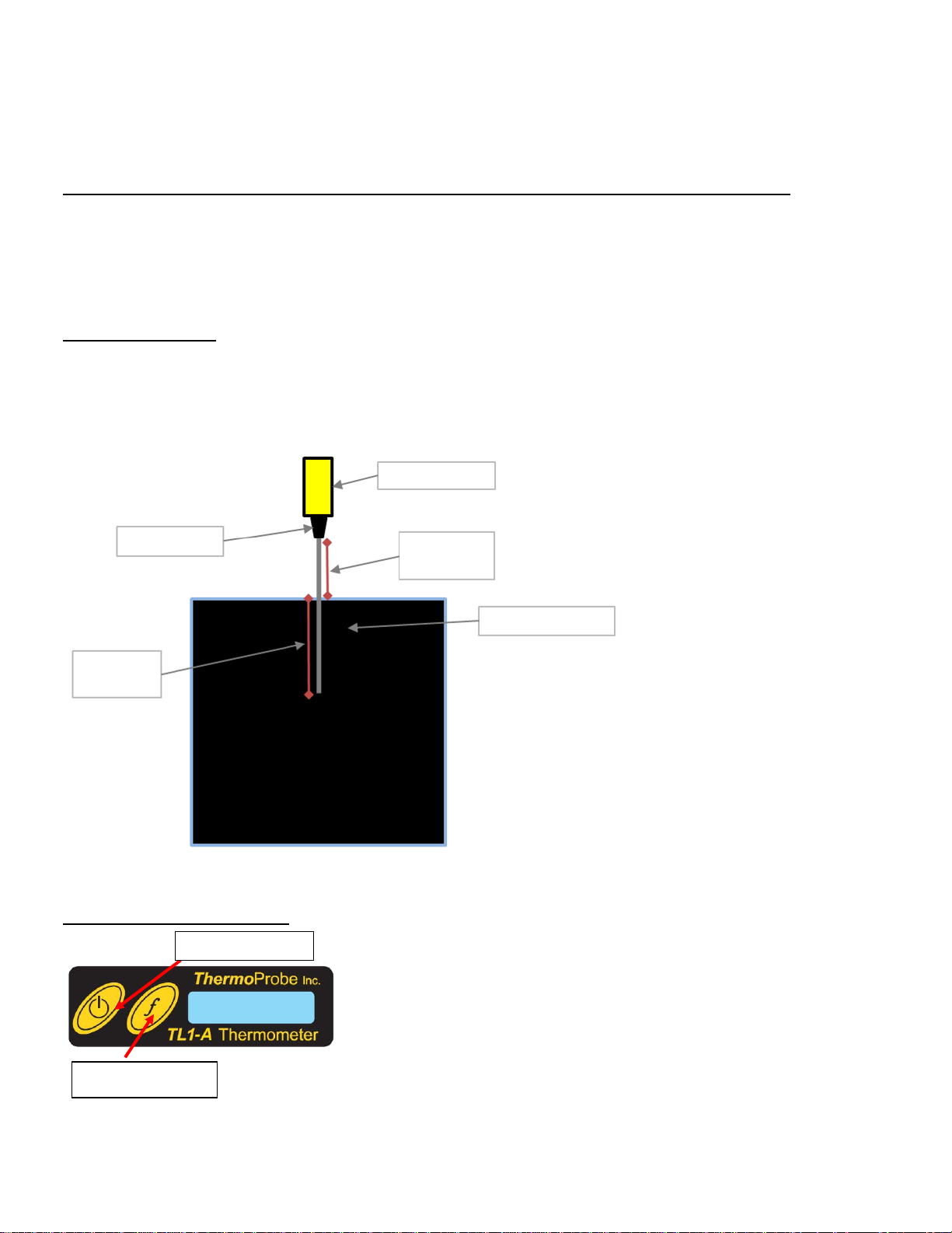
d) Bei Modellen mit Batterien vom Typ „AAA“ (Micro) muss der Benutzer darauf achten, dass der Gummi-Abstandshalter nac h de m
Funktionstaste
TL-Thermometer
Sensorhalterung
5-cmMindestabstand
Temperaturquelle
Eintauchtiefe
Batteriewechsel nic ht entfernt wird. Auf diese Weise können sich die Ba t terien während des Gebrauchs nicht verschieben.
e) Die hintere Abdeckung wieder anbringen und mit den 2 Schrauben befe s t igen.
Die folgenden Batterien wurden für den Gebrauch mit diesem Instrument ZERTIFIZIERT:
Modell Hersteller Typ Bestell-Nr.
TL1-W, TL1-R Duracell AAA (LR03) Alkali MN2400
TL1-W, TL1-R Panasonic AAA (LR03) Alkali LR03XWA
TL1-W, TL1-R Gold Peak AAA (LR03) Alkali GP24A
TL1-A Duracell CR2032 LiMnO
2
DL2032
EINTAUCHTIEFE
Für optimale Messergebnisse wird eine Mindesteintauchtiefe von 10 cm in die Temperaturquelle empfohlen.
Bei allen TL1-Modellen muss ein Mindestabstand zwischen der Sensorhalterung und der Temperaturquelle aufrechterhalten werden,
damit das Thermometergehäuse nicht wärmer als 40 °C wird.
Abb. 1: TL1-Eintauchtiefe
BENUTZEROBERFLÄCHE
09/2012, JK
Page 35

Einmal kurz drücken
Gerät ein
4 Sekunden halten
Aktivierung des
Dauerbetriebs
*Drücken und loslassen
Einschalten der
Hintergrundbeleuc htung für
10 Sek.
Drücken und loslassen
„Fn“
Zeigt niedrigsten, gemittelten und höchsten
Messwert an
„C-F“
2
Ändert die Anzeigeauflösung (0,1, 0,01 oder
0,001)
„ZERo“
3
Zeigt Nullabgleich an
„0.005“
Betriebstaste
Durch einmaliges Drücken der Betriebstaste wird das Gerät eingeschaltet. Binnen 20 Minuten schaltet sich das Instrument
automatisch wieder aus.
Wenn die Betriebstaste gedrückt und 4 Sekunden lang gehalten wird, wird die automatische Ausschaltfunktion deaktiviert. (Als
Hinweis auf den Dauerbetrieb blinkt kurz das Wort „Conn“ auf dem Display.)
Durch Gedrückthalten der Betriebstaste wird das Instrument ausgeschaltet; alle gespeicherten und gemittelten Messergebnisse
werden gelöscht.
Betriebstaste
bei Anzeige von „LigHt“
bei Anzeige von „oFF“
Funktion Anzeige
Gerät aus
(Setzt Messungen zurück)
„Conn“
„LigHt“
“oFF”
* Nur Modell TL1-W
Funktionstaste „f“
Durch Gedrückthalten der Funktionstaste f werden die Optionen im Menü-Format angezeigt. Bei Anzeige der gewünschten Funktion
„dEC“
Funktion („f“) Beispiel auf Display
78.61 L, 78.70 A, 78.93 H
Wechselt zur jeweils anderen Maßeinheit „76.3 F“ oder „24.6 C“
„76.3 F“ oder „24.6 C“
die Taste loslassen.
Halten und loslassen bei
Anzeige von:
Anmerkungen:
1. Sobald das TL1 eingeschaltet wird, werden die Minimal-, Maximal- und Durchschnittsdaten laufend aktualisiert. Nach dem
Einschalten und vor dem Anzeigen des minimalen, gemittelten und maximalen Werts 20 Sekunden warten, damit das Gerät
die Daten erfassen kann.
2. Die Auflösung von 0,001 ist nur bei TL1-R-Modellen verfügbar.
3. Der Nullabgleich ist nur bei TL1-R-Modellen verfügbar.
Display-Pfeile
Die Pfeile auf der linken Seite des Displays zeigen Ihnen auf einen Blick, ob die gemessene Temperatur ansteigt, sinkt oder sich
stabilisiert hat. Dabei steht der Aufwärtspfeil für einen Anstieg der Temperatur, der Abwärtspfeil für eine Abnahme der Temperatur
und das Fehlen des Pfeils für eine Stabilisierung.
Batterieprüfung
Bei einer niedrigen Batteriespannung erscheint auf dem Display der Hinweis „Lo bAtt“, bevor die normale Anzeigefunktion wieder
aufgenommen wird. Wenn „Lo bAtt“ angezeigt wurde, darf kein Versuch zur Kalibrierung des Instruments unternommen werden,
da die neuen Kalibrierungswerte evtl. nicht korrekt gespeichert werden.
09/2012, JK
Page 36

Fehlercodes
ThermoProbe, Inc.
ErrHI verweist auf eine Messung über dem Messbereich, d. h. die Temperatur am Sensor übersteigt den spezifizierten Grenzwert des
Geräts. Dieser Code kann auch auf einen offenen Stromkreis hinweisen, der evtl. eine Reparatur des Geräts erforderlich macht.
ErrLO verweist auf eine Messung unter dem Messbereich, d. h. die Temperatur am Sensor liegt unter dem spezifizierten Grenzwert
des Geräts. Dieser Code kann auch auf einen Kurzschluss hinweisen, der evtl. eine Reparatur des Geräts erforderlich macht.
NULLABGLEICHMODUS: (Nur Modell TL1-R)
Hinweis: Die hier durchgeführten Korrekturen wirken sich auf den gesamten Temperaturbereich des Geräts aus.
1. Gleichzeitig die Funktions- und Betriebstaste drücken. Beide Tasten loslassen, wenn „AdJ“ angezeigt wird. Damit wird der
Nullabgleichmodus a u f gerufen.
2. Im Nullabgleichmodus die Betriebstaste drücken und gedrückt halten und „UP“, „dn“, „SAVE“, „no SAVE“ oder „CAnC“
wählen.
3. Durch Auswahl von „UP“ und Drücken der Funktionstaste kann die Temperatur nach oben korrigiert werden.
4. Durch Auswahl von „dn“ und Drücken der Funktionstaste kann die Temperatur nach unten korrigiert werden.
5. Bei Auswahl von „CAnC“ („Cancel“ – Abbrechen) bleibt das Gerät im Nullabgleichmodus, sodass weitere Korrekturen
vorgenommen werde n können.
6. Zum Speichern der vorgenommenen Korrekturen und Beenden des Nullabgleichmodus die Betriebstaste gedrückt halten, bis
„SAVE“ (Speichern) angezeigt wird.
7. Zum Beenden des Nullabglei c hmodus, ohne Veränder u ngen vorgenommen zu haben, die Betriebstaste ge d rückt halten, bis
„no SAVE“ (nicht speichern) angezeigt wird.
8. Das Instrument schaltet wieder auf den Normalbetrie b um.
9. Um den Nullabgleich kurz im Normalmenü anzuzeigen, die Funktionstaste gedrückt halten und loslassen, sobald „ZERo“
(Null) angezeigt wird.
KALIBRIERUNG
Kalibrierungen werden von ThermoProbe, I nc . u nd seinen Vertragshändl ern durchgeführt. Falls eine Kalibrierung vor Ort gewünscht
wird, wenden Sie sich bzgl. der dafür zu beachtenden Anforderungen bitte an ThermoProbe, Inc.
AUTORISIERTE REPARATUREN
Es wird empfohlen, Wartungs- und Reparaturmaßnahmen, die über den in dieser Anleitung besch r i e benen Umfang hinausge hen, von
ThermoProbe, Inc. oder einem der Vertragshändler des Unternehmens durchführen zu lassen.
112A JETPORT DR.
PEARL, MS 39208
Tel.: +1 601.939.1831
Fax: +1 601.355.1831
sales@thermoprobe.net
www.thermoprobe.net
09/2012, JK
Page 37

KONFORMITÄTSERKLÄRUNG
Gerätebezeichnung ThermoProbe Inc. Modelle TP7-C, TP9, TL1-A, TL1-W und TL1-R
Portable Digitalthermometer
Geräteklassifizierung
Konformitätserklärung
Auf der Grundlage von Musterprodukt-Testergebnissen unter Anwendung der entsprechenden
Normen (Industrieumgebung) und gemäß den folgenden EG-Richtlinien erklärt ThermoProbe Inc.
hiermit, dass die Modelle TP7-C, TP9, TL1-A, TL1-W und TL1-R konform sind mit:
EG ATEX-Richtlinie 94/9/EG, Geräte und Schutzsysteme
zur Verwendung in explosionsgefährdeten Bereichen.
Musterprodukttest für ATEX
Geprüft von
Angewandte Normen
EN 60079-11: 2007
Bericht-ID
Hersteller
112A Jeport Dr.
Pearl, MS 39208 USA
Luke Bartkiewicz
President
DEMKO
11K04891
ThermoProbe Inc.
Messgerät
EN 60079-0: 2009
5. 10. 2012 JK
 Loading...