

Thermo Pride OL5-85RDBP, OT11-105FBP, OL16-125FDBE, OT16-125FBP, OL11-105FDBP Installation And Operation Manual
...
OIL FIRED FURNACE
INSTALLATION AND OPERATION MANUAL
WITH USERS INFORMATION SECTION
MODELS:
OT11-105FBP OL5-85FDBP OL16-125FDBP
OT11-105RBP OL5-85RDBP OL16-125FDBE
OT16-125FBP OL11-105FDBP OL16-125RDBP
OT16-125RBP OL11-105FDBE OL16-125RDBE
OL11-105RDBP
OL11-105RDBE
c WARNING
OR EXPLOSION MAY RESULT CAUSING PROPERTY DAMAGE, PERSONAL INJURY, OR LOSS OF LIFE.
DO NOT STORE OR USE GASOLINE OR OTHER FLAMMABLE VAPORS AND LIQUIDS IN THE VICINITY OF
THIS OR ANY OTHER APPLIANCE.
c WARNING:
CAN CAUSE INJURY OR PROPERTY DAMAGE. REFER TO THIS MANUAL. FOR ASSISTANCE OR
ADDITIONAL INFORMATION CONSULT A QUALIFIED INSTALLER, OR SERVICE AGENCY.
PLEASE READ THESE INSTRUCTIONS PRIOR TO INSTALLATION, INITIAL FIRING, AND BEFORE
PERFORMING ANY SERVICE OR MAINTENANCE. THESE INSTRUCTIONS MUST BE LEFT WITH THE
USER AND SHOULD BE RETAINED FOR FUTURE REFERENCE BY QUALIFIED SERVICE PERSONNEL.
THERMO PRODUCTS, LLC.
PO BOX 217
NORTH JUDSON, IN 46366
PHONE: (574) 896-2133
MO-506
ECN 5397-MA 150105
: IF THE INFORMATION IN THESE INSTRUCTIONS IS NOT FOLLOWED EXACTLY, A FIRE
IMPROPER INSTALLATION, ADJUSTMENT, ALTERATION, SERVICE, OR MAINTENANCE
MADE IN USA

I. SAFETY SECTION
This page contains various warnings and cautions found throughout the Oil Furnace
Manual. Please read and comply with the statements below.
cWARNING AND CAUTIONS:
cWARNING: This furnace is not to be used as a construction heater. See Page 2.
c CAUTION MUST BE TAKEN NOT TO EXCEED 90° ROTATION (OF THE FLUE
ELBOW) COUNTERCLOCKWISE FROM THE VERTICAL POSITION. See Page 3.
cWARNING: The predetermined limit locations on all of the Thermo Pride oil fired furnaces
have been tested and approved by Thermo Products, LLC. In conjunction with Underwriters
Laboratories, Inc. Any attempt to relocate these safety controls or replace these safety controls
with a control that is not approved, or is incompatible, may result in personal injury, substantial
property damage or death. See Page 4.
cWARNING: THE HEAT EXCHANGER MUST BE CLEANED BY A QUALIFIED
SERVICE PERSON. See Page 9.
cCAUTION: DO NOT ATTEMPT TO MAKE REPAIRS YOURSELF! See Page 11.
cWARNING: The area around the furnace should be kept free and clear of combustible
liquids and material, especially papers and rags. See Page 11.
cWARNING: NEVER burn garbage or refuse in your furnace. Never try to ignite oil by
tossing burning papers or other material into your furnace. See Page 11.
cWARNING: Thermo Products oil furnaces are designed to burn No. 1 or No. 2 distillate
fuel oil. NEVER USE GASOLINE OR A MIXTURE OF OIL AND GASOLINE. See Page
11.
cCAUTION: DO NOT ATTEMPT TO START THE BURNER WHEN:
1. Excess oil has accumulated,
2. The furnace is full of vapors
3. The combustion chamber is very hot.
IF ONE OR MORE OF THESE CONDITIONS EXIST, CONTACT A QUALIFIED
SERVICE PERSON. See Page 11.
i
All installations and services must be performed by qualified service personnel.
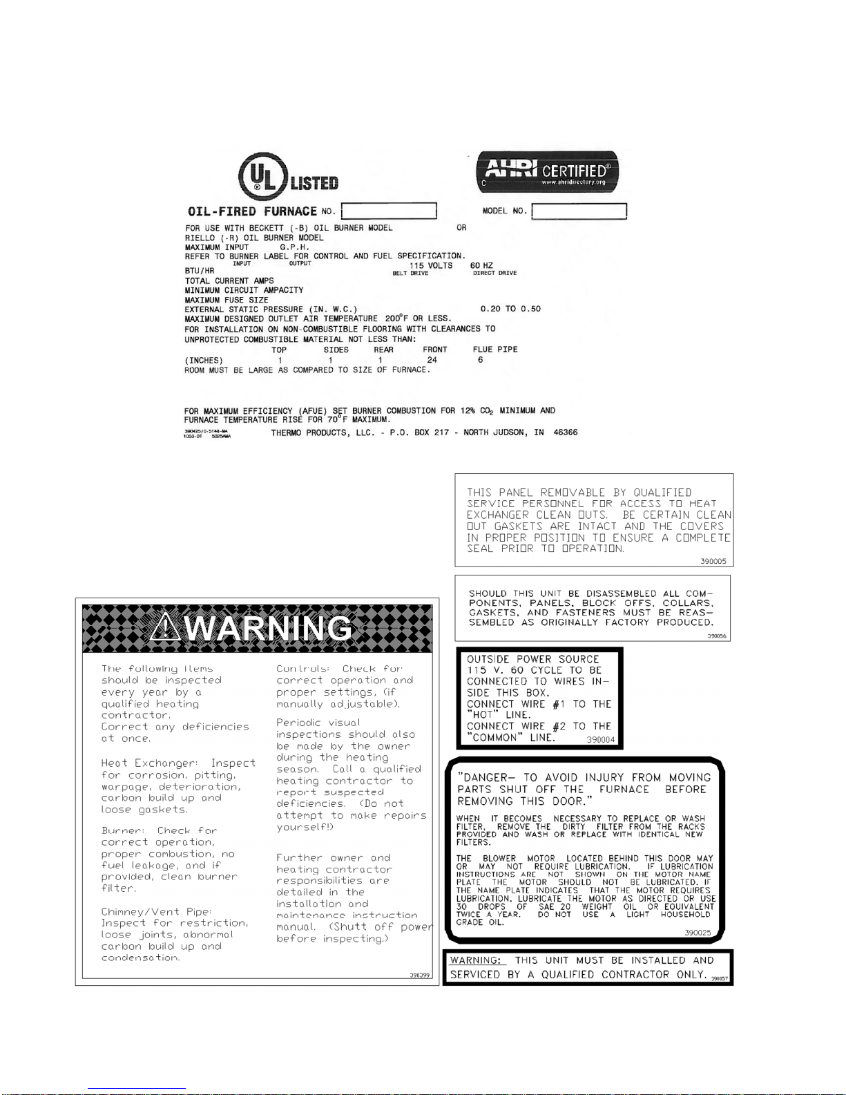
This page contains reproductions of the various instruction and warning labels placed on
the Thermo Pride Oil Furnaces. Please read and comply with the contents of these labels.
ii

All installations and services must be performed by qualified service personnel.
TABLE OF CONTENTS
SECTION BEGINNING PAGE
I. SAFETY SECTION i
II. GENERAL INSTRUCTIONS 2
A. DRAFT REGULATORS 3
B. DUCT WORK/AIR CONDITIONING 4
C. HORIZONTAL FURNACE POSITIONS 5
D. LIMIT POSITION AND LOCATION 5
E. BURNER INSTALLATION 6
F. EXTERNAL WIRE HARNESS LOCATIONS 8
G. BURNER SPECIFICATIONS AND APPLICATIONS 8
H. HEAT EXCHANGER CLEANING INSTRUCTIONS 9
III. USERS INFORMATION SECTION 11
A. OIL SUPPLY 11
B. COMBUSTION AIR SUPPLY 11
C. INSPECTION AREAS 11
D. STARTING THE BURNER 11
E. FILTER CLEANING AND LOCATION 12
APPENDIX – A REPLACEMENT PARTS LIST 14
APPENDIX – B WIRING DIAGRAMS 23
iii

All installations and services must be performed by qualified service personnel.
.75X80
°A
.90X80
°A
1.10X80
°A
.90X80
°A
.90X80
°A
1.10X80
°A
1.10X80
°A
Packing List
This Thermo Pride furnace was shipped from the factory with the below listed items for the final
installation. Please contact Thermo Pride Customer Service if you are missing any of the items.
LOWBOY UNITS: OL5 OL11 OL16
ROCKWOOL INSULATION 1 BAG 1 BAG 1 BAG
DOOR HANDLE 2 SETS 2 SETS 2 SETS
DRAFT REGULATOR 6" 6" 7"
OIL NOZZLE
WIRE NUTS 74B 2 2 2
BUSHING UB-875 1 1 1
BUSHING 34-2 1 1 1
LITERATURE PACKAGE 1 1 1
HORIZONTAL UNITS: OT11F OT11R OT16F OT16R
ROCKWOOL INSULATION 1 BAG 1 BAG 1 BAG 1 BAG
DOOR HANDLE 1 SET 1 SET 1 SET 1 SET
DRAFT REGULATOR 6" 6" 7" 7"
OIL NOZZLE
WIRE NUTS 74 B 2 2 2 2
BUSHING UB-875 1 1 1 1
LITERATURE PACKAGE 1 1 1 1
THERMO PRIDE EMBLEM 1 1 1 1
LIMIT COVER w\ LABEL 1 - 1 COVER PLATE 1 - 1 SCREWS, 8X1/2 3 - 3 -
1
All installations and services must be performed by qualified service personnel.
II. GENERAL INSTRUCTIONS - READ BEFORE START OF INSTALLATION
1. The heating output capacity of the furnace proposed for installation should be based on a heat loss calculation
made according to the manuals provided by the Air Conditioning Contractors of America (ACCA) or the American
Society of Heating, Refrigeration and Air Conditioning Engineers, Inc. (ASHRAE).
2. All local codes and/or regulations take precedence over the instructions in this manual and should be followed
accordingly. In the absence of local codes, installation must conform with these instructions and regulations of the
National Fire Protection Association, and to the provisions of the National Electrical Code (ANSI/NFPA 70-1999 or
latest edition).
3. The installed furnace must be level and positioned in a central location with respect to outlet registers. It should
be located near the chimney to minimize any horizontal run of flue pipe, which may be required.
4. A furnace installed in a residential garage must be installed so the burner and ignition source are located higher
than 18 inches above the floor, unless the required combustion air is taken from the exterior of the garage. Also, the
furnace must be located or protected to avoid physical damage by vehicles.
cWARNING: This furnace is not to be used as a construction heater.
5. Listed below are definitions of "COMBUSTIBLE MATERIAL" and "NON-COMBUSTIBLE MATERIAL."
COMBUSTIBLE MATERIAL:
Material made of or surfaced with wood, compressed paper, plant fibers, plastics, or other material that will ignite
and burn, whether flame resistant or not.
NON-COMBUSTIBLE MATERIAL:
Material that is not capable of being ignited and burned. Such materials consist entirely of, or a combination of,
steel, iron, brick, tile, concrete, slate, or glass.
TYPE OF UNIT
LOWBOYS
TYPE OF UNIT
HORIZONTALS2
Notes:
The minimum clearances listed in the preceding table are for fire protection. Clearance for servicing the front of the
furnace and the rear of the lowboy models should be at least 24 inches. A clearance of 24 inches is recommended
for passage to all points on the furnace requiring service access.
NOTE: When power venting a Thermo Pride oil fired furnace with a power venting system other than the system
supplied by Thermo Pride, a fiber chamber and an isolated combustion air kit (PVB or Beckett boot) is to be used
with the other manufacturers power venting system.
MINIMUM CLEARANCES TO COMBUSTIBLE MATERIALS
MODEL
NO.1
FROM SIDES
OF FURNACE
FRONT
TOP &
SIDES OF
PLENUM
FROM THE
FLUE/VENT
OL5,11,16 1” 24” 1” 6” 1”
MODEL
NO.1
FRONT TOP REAR BOTTOM FROM THE
FLUE/VENT
ANY SIDE
PLENUM
OT11,16 24” 1” 1” 1” 9” 1”
1
The above are abbreviated model numbers.
2
Horizontal units are not approved for attic installation.
REAR
OF
2
All installations and services must be performed by qualified service personnel.
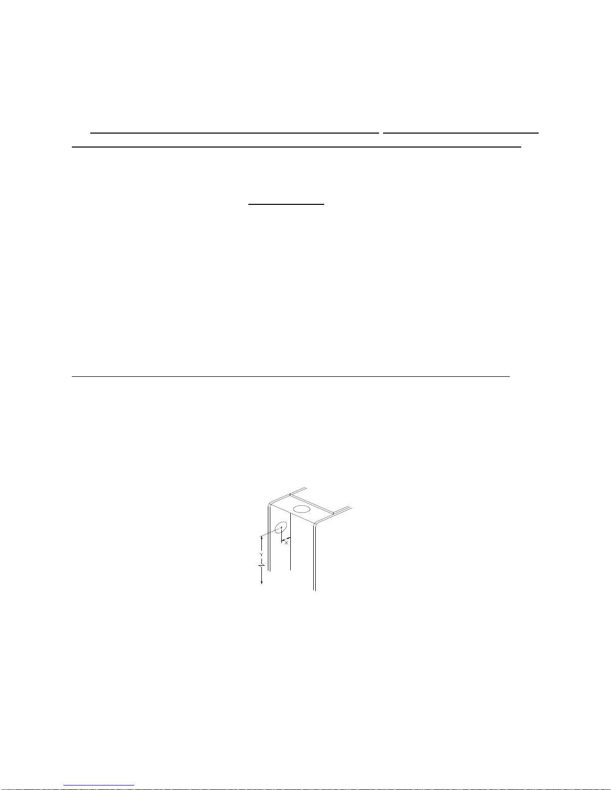
NOTE: On the front flue, lowboy, it is possible to rotate the flue elbow (which is factory installed for vertical
discharge) 90° counterclockwise from the vertical position to adapt to various venting systems. (See following page
for details)
c CAUTION MUST BE TAKEN NOT TO EXCEED 90° ROTATION (OF THE FLUE
ELBOW) COUNTERCLOCKWISE OR RIGHT FROM THE VERTICAL POSITION.
ROTATION OF FRONT FLUE ELBOW
When an installation requires that the flue exit out the left hand side casing on a front flue unit, remove screw
securing the 90 deg. elbow and rotate it 90° counterclockwise. Then, by following dimensions in Table 1, locate the
center point for the exit of the flue for the particular size furnace. Once the center has been located, use a scribe to
mark the hole size, listed in the chart, which corresponds with the furnace being used. Cut hole out and extend flue
through side casing.
A trim collar may be ordered from Thermo Products to hide the gap around the flue pipe. This trim collar, however,
is not required for operation.
NOTE: ROTATION OF FLUE PIPE IS ONLY ALLOWED FOR LEFT HAND SIDE VENTING
APPLICATIONS.
TABLE 1: Suggested sizes and positions of flue pipe opening on left hand side of casing.
TRIM COLLAR/
UNIT DIA. HOLE “X” DIM. “Y” DIM. FLUE DIA. GASKET PART #
OL5* 6-1/2” 4-5/8” 34-15/16” 6” 14131/330005
OL11* 6-1/2” 4-1/2” 37-5/8” 6” 14131/330005
OL16* 7-1/2” 4-1/2” 39-1/8” 7” 14132/330006
* FRONT FLUE MODELS ONLY
“X” DIMENSION IS MEASURED FROM SEPARATOR PANEL.
“Y” DIMENSION IS MEASURED FROM THE BASE ON “L” MODELS.
Fig 1: Recommended location for drilling hole to connect
vent pipe to the furnace through the left hand side casing.
A. DRAFT REGULATORS:
A draft regulator is supplied with the furnace and should be installed according to the regulator manufacturers
recommendations. With the burner operating, use a draft gauge to adjust the regulator to the proper setting. (refer to
the instructions enclosed with draft regulator to adjust to the proper setting). When the burner air supply and draft
are properly adjusted, the overfire draft should be a negative (-).01" to (-).02" WC, as measured at the 5/16" overfire
3
All installations and services must be performed by qualified service personnel.
air tap (See Fig. 8). This tap is provided in the upper burner mounting plate. To measure the flue draft, punch a small
hole in the vent connector pipe as close to the furnace as possible and always before the draft regulator.
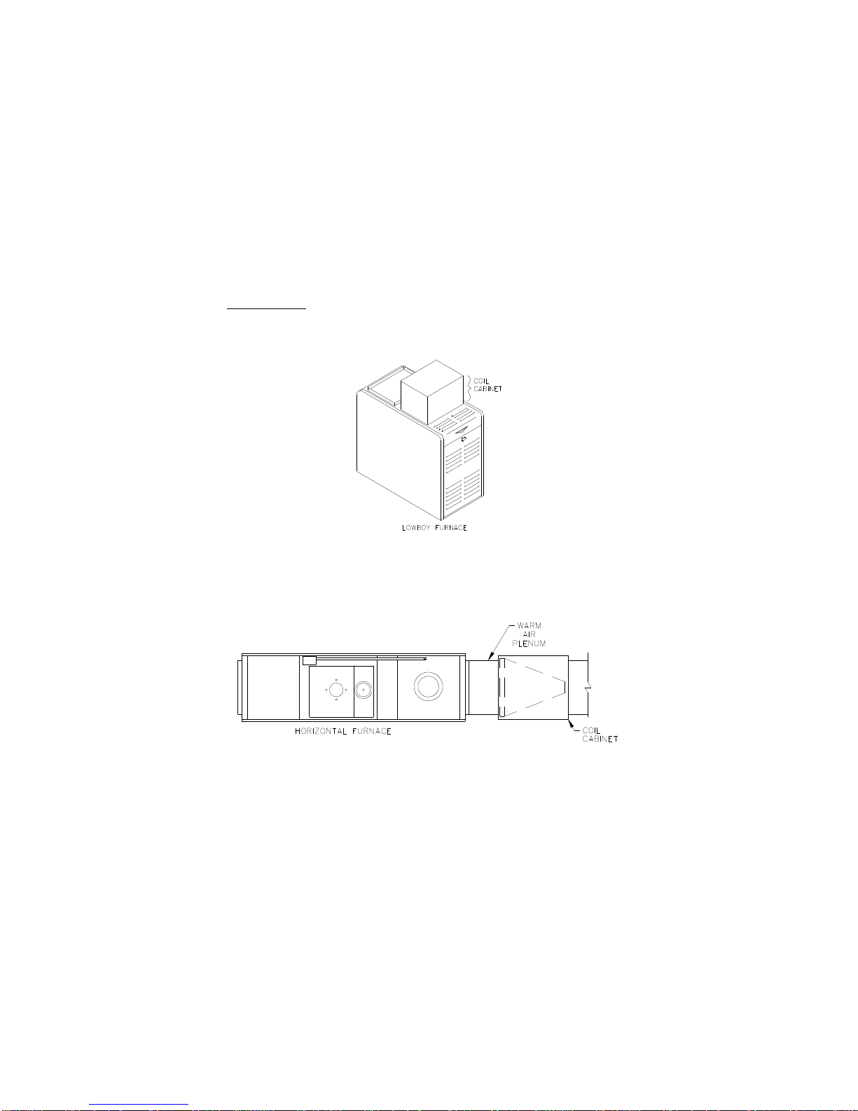
B. DUCT WORK/AIR CONDITIONING:
If the furnace is used in connection with summer air conditioning (cooling), the furnace should be installed parallel
with or on the upstream side of the evaporator coil to avoid condensation in the furnace heat exchanger. If the
cooling unit is installed with a parallel flow arrangement, dampers or other means used to control flow of air should
be provided to prevent chilled air from entering the furnace. If such a damper is manually operated, it must be
equipped with a means to prevent operation of either unit, unless the damper is in the full heat or cool position.
The duct system should again follow the current design standard of Air Conditioning Contractors of America
(ACCA) or ASHRAE Fundamentals volume.
The most common location for the A-shaped coil (A style) is shown in Fig. 2.
Fig 2: Acceptable locations for the air conditioner evaporator coil.
NOTICE: The minimum coil pan clearance for a sectional or drum type heat exchanger is three inches unless
specified otherwise by the individual coil manufacturer.
Fig. 3: An acceptable location for the air conditioner evaporator coil when used with a horizontal furnace.
To obtain proper airflow with an air conditioning coil installed on a direct drive unit the blower motor speed may
need to be changed depending upon the size of the air conditioning system installed and the airflow resistance of the
duct system.
Refer to wiring diagrams for blower motor speed selection tables. Nominal temperature rise range is 55° F to 85° F.
4
All installations and services must be performed by qualified service personnel.
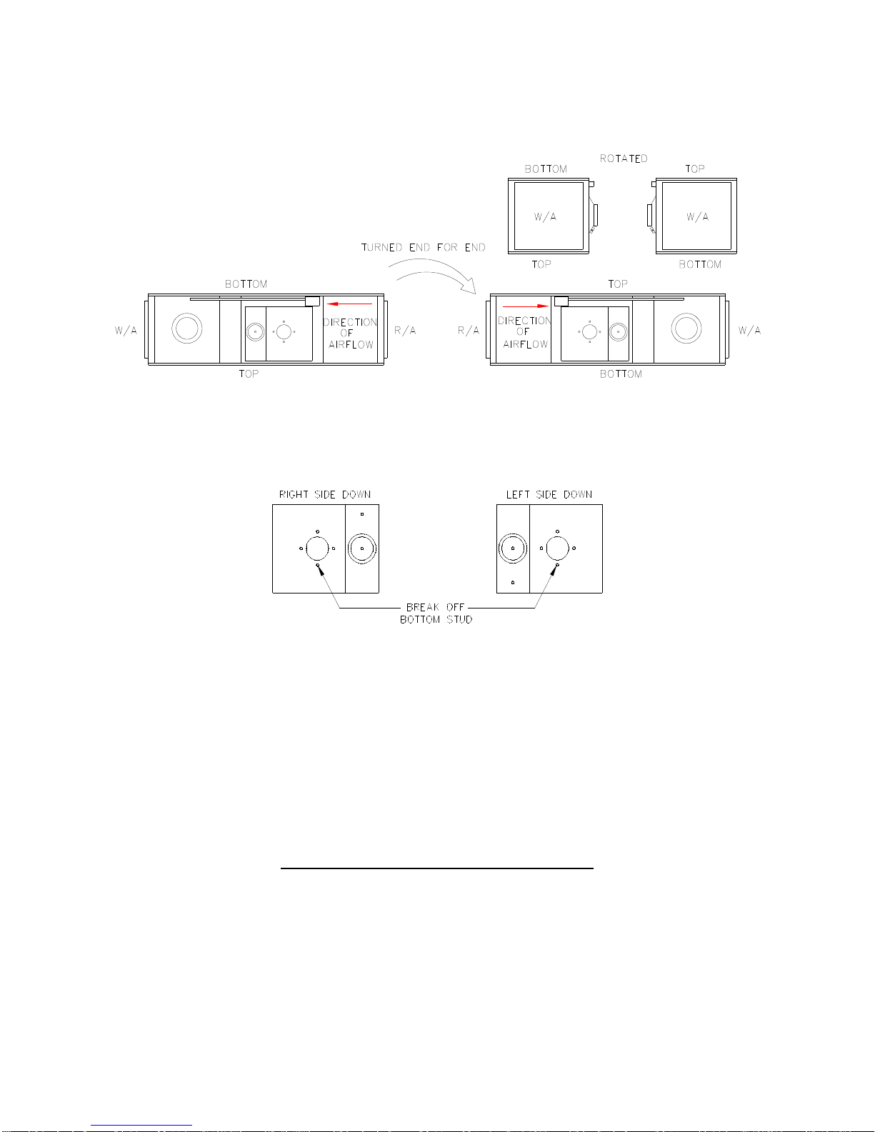
C. HORIZONTAL FURNACE POSITIONS:
The horizontal furnace may be turned end for end, or rotated, making the top into the bottom, as shown in Fig. 11.
After the furnace has been positioned, the bottom burner mounting stud must be broken off before mounting the
burner (See Fig. 12).
D. LIMIT POSITION AND LOCATION
cWARNING: The predetermined limit locations on all of the Thermo Pride oil fired furnaces have been tested
and approved by Thermo Products, LLC. in conjunction with Underwriters Laboratories, Inc. Any attempt to
relocate these safety controls or replace these safety controls with a control that is not approved, or is incompatible,
may result in personal injury, substantial property damage or death.
The T11 & T16 Front Flue furnaces only are shipped with two limits installed in the discharge air end of the
furnace. After it has been determined in what direction the furnace will be installed, the correct limit will be
connected to the limit harness.
For the T11 or T16 Front Flue installed with the discharge air to the left (when facing burner, See fig 7A) The limit
at the upper left of the furnace is to be used (T11=350264 160oF, T16=350817 150oF) Attach the harness to the
limit cover from parts bag. Then connect the limit leads to the limit terminals. At this time the cover can be
mounted to the cover the limit. The unused limit must now be removed. The opening that is left should be covered
with the provided cover plate found in the parts bag.
Fig. 11: A horizontal furnace rotated 180° (or flipped end for end) to reverse airflow direction
Fig. 12: Required modification to burner mounting studs before burner installation
Limit connection for T11 & T16 Front Flue Models
5
 Loading...