


OUTDOOR COMBINATION OIL-FIRED FURNACE AND AIR CONDITIONING UNIT MODEL OPA
INSTALLATION AND SERVICE MANUAL


 : If the information in this manual is not followed exactly, a fire or explosion may result causing property damage, personal injury, or loss of life.
−Do not store or use gasoline or other flammable vapors and liquids in the vicinity of this or any other appliance.
−WHAT TO DO IF YOU FIND AN OIL LEAK:
•Do not try to light any appliance.
•Immediately call your oil supplier.
•If you cannot reach your oil supplier, call the fire department.
−Installation and service must be performed by a qualified installer, service agency or the oil supplier. (These entities are referred to in these instructions as a qualified heating contractor).
Please read these instructions prior to installation, initial firing, and before performing any service or maintenance.
These instructions must be retained by the homeowner for future reference by qualified heating contractor.
|
Thermo Products, LLC |
|
|
PO Box 217 |
|
MO-424 |
North Judson, IN 46366 |
|
ECN 4650-MA |
Phone: (574) 896-2133 |
Made In USA |
All installations and services must be performed by qualified service personnel.
Contents
SECTION |
PAGE |
I.SAFETY INFORMATION .............................…………………………………….3
II.GENERAL INSTRUCTIONS ...........................................………………….…..9
III.GENERAL INSTALLATION .....................................................………………. 9
A.Codes and Clearances .......................................................……………. 10
B.Selection of Installation Location .........................................…………… 11
C.Venting Of Combustion Products ............................................………….13
D.Condensate Drain ....................................................................…………14
E. Oil Tank and Piping ..................................................................... |
……... 15 |
F.Oil Filter .......................................................................................……… 17
G.Burner Specifications and Performance .......................................…….. 17
H.Airflow Requirements and Sizing of Ductwork ..............................…….. 19
I.Air Filters ......................................................................................…….. 23
1.Filter Installation ......................................................................…….. 23
2.Use of non-Thermo Pride Filters or Retention Means ..............……. 23
J.Electrical Wiring .............................................................................……. 24
1.Electronic Air Cleaner (EAC) and Humidifier Installation ..........…… 26
2.Thermostat Anticipator Setting.................................................…….. 28
3.Blower Motor Speed Selection .................................................……. 30
IV. STARTUP PROCEDURES.........................................................................…….32
A.HEATING SYSTEM
1.Initial Startup .............................................................................…….32
2.Adjustment of Burner Combustion .............................................…… 34
3.Adjustment of Heat Input Rate ...................................................……37
4.Setting Supply Air Temperature Rise .....................................……... 38
5.Checkout Procedure ................................................................…….. 39
B.COOLING SYSTEM
1. Initial Startup ......................................................................….……... 41
2. Definition of Superheat .......................................................... |
……... 42 |
3.Evaporator Superheat ...........................................................………. 43
4.Definition of Subcooling ..........................................................…….. 44
5.Condenser Subcooling ...........................................................…….. 44
6. Recommendations for Operation at Low Temperatures ............… 45
V.INSTALLER'S INSTRUCTIONS TO USER ..........................................….. 46
1
All installations and services must be performed by qualified service personnel.
|
Contents |
SECTION |
PAGE |
VI. DEALER MAINTENANCE |
................................................................ ……... 47 |
A. General Inspection ...................................................................... |
……... 47 |
B.Heat Exchanger ........................................................................………. 48
1.Disassembly to Access Heat Exchanger ...............................……… 48
2.Reassembly of Unit ................................................................……… 50
3.Operational Check ..................................................................…….. 51
C.Electrical System ...........................................................................……. 51
D.Supply/Return Air Blower .............................................................……... 52
E. Supply/Return Air Filter ................................................................…….. 52
1.Filter Maintenance ...................................................................…….. 52
2.Filter Replacement ...................................................................……. 52 F. Extended Appliance Shutdown ....................................................……... 53
VII. HOMEOWNER/USER INFORMATION AND ROUTINE MAINTENANCE ..55
VIII. TROUBLESHOOTING .........................................................................…… 59
A.Heating System ................................................................................….. 59
B.Cooling System .................................................................................…. 60
IX. |
REFERENCES .......................................................................................…. 62 |
X.APPENDIX A: SOURCES FOR REFERENCED STANDARDS .............…. 63
XI. |
APPENDIX B: CALCULATIONS ...........................................................….. 64 |
XII. |
APPENDIX C: ELECTRICAL SCHEMATIC AND CONNECTION DIAGRAM |
|
.................................................................................................................….75 |
XIII. |
APPENDIX D: SEQUENCE OF OPERATIONS ....................................….. 76 |
XIV. |
APPENDIX E: TROUBLESHOOTING FLOWCHARTS .........................….. 78 |
XV. |
APPENDIX F: SPECIFICATION SHEETS .............................................…. 86 |
XVI. |
APPENDIX G: REPLACEMENT PARTS ...............................................….. 87 |
XVII. |
APPENDIX H: OPA HEATING AND COOLING TEST FORM ...............…. 89 |
|
WARRANTY …………………………………………………………………….. 90 |
2

All installations and services must be performed by qualified service personnel.
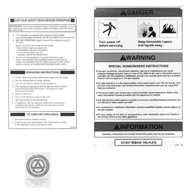
I. SAFETY INFORMATION
This page and the following page contain reproductions of the various instructions and warning labels placed on the Thermo Pride gas-fired appliances. Please read and comply with the contents of these labels.
3
All installations and services must be performed by qualified service personnel.
4

All installations and services must be performed by qualified service personnel.
The following warnings and cautions are found throughout the Thermo Pride Model OPA Installation and Service Manual. Please read and comply with the statements below.


 : IF YOU DO NOT FOLLOW THESE INSTRUCTIONS EXACTLY, A FIRE OR EXPLOSION MAY RESULT CAUSING PROPERTY DAMAGE, PERSONAL INJURY, OR LOSS OF LIFE.


 : Carefully read and thoroughly understand the following guidelines and warnings before continuing with the installation of this unit. Failure to follow these guidelines can cause improper and unsafe operation of this appliance. Unsafe operation can result in substantial property damage, severe personal injury, or death.


 : This unit is not to be used for temporary heating of buildings, or structures, under construction.


 : Maximum gross stack temperature must not exceed 550°F (288°C) under any circumstances.


 : Failure to comply with minimum filter installation requirements may effect the performance and/or void the warranty on this unit.


 : This appliance must be grounded in accordance with local codes or in the absence of local codes with the National Electrical Code, ANSI/NFPA 70 –1999, or the latest edition.


 : Turn off the electrical power to the appliance before attempting to change supply air blower speed wiring.


 : Personal injury or property damage could result from repair, or service, of this appliance by anyone other than a qualified heating contractor. The end user may only perform the service described under the Homeowner/User Routine Maintenance section of this manual.


 : To avoid injury from moving parts or electrical shock, shut off the power to the appliance before removing supply air blower compartment door and servicing this appliance.


 : When servicing controls, label all wires prior to disconnecting. Reconnect any wires removed correctly. Wiring errors can cause improper and dangerous operation. Dangerous operation can result in injury or damage.


 : Disconnect electrical power before servicing this unit.
5

All installations and services must be performed by qualified service personnel.


 : Waterproof type connectors must be used when connecting electrical power and control wiring to the unit to prevent moisture from being drawn into the unit during operation.


 : Refrigerant is under pressure. Guard against refrigerant spraying into the face or on skin. Always wear protective equipment, i.e. safety glasses or goggles and gloves when working with refrigerant.


 : Do not under any circumstances heat the refrigerant cylinder with a torch or by any other means other than warm water. Excessive pressures generated in this manner may weaken the refrigerant container and result in an explosion!


 : To avoid injury from moving parts, or electrical shock, shut off the power to the appliance before removing blower compartment door and servicing this appliance.


 : When servicing controls, label all wires prior to disconnecting. Reconnect any removed wires correctly. Wiring errors can cause improper and dangerous operation. Dangerous operation can result in injury or damage.


 : Do not use this appliance if any part has been under water. Immediately call a qualified service technician to inspect the furnace and to replace any part of the control system and any gas control that has been under water.


 : The area around the appliance, including the top of the unit, must be kept clear and free of combustible materials, gasoline, and other flammable vapors and liquids.


 : The appliance vent terminal may be hot. If the terminal is hot, allow it to cool before touching it.


 : Shut off unit and disconnect the power source before disassembling the unit.


 : Never operate the appliance without clean air filters in place.


 : This appliance requires air for combustion, ventilation, and cooling. Do not block or obstruct air openings in the unit and the air space around the perimeter of the unit.


 : All local codes and ordinances take precedence with regard to selection and installation of oil storage tank and oil supply (and return) lines. In the absence of local codes, all tanks and lines must be selected and installed according to the instructions in this manual and the Standard for the Installation of Oil-Burning Equipment, NFPA 311997, or the latest edition.


 : Turn off power to furnace. Before the oil piping system is placed into service, it must have been leak tested by a qualified heating contractor.
6

All installations and services must be performed by qualified service personnel.


 : For initial start-up of the appliance after installation, it may be necessary to purge the air out of the oil line. A qualified heating contractor should do this.


 : If you do not follow these instructions exactly, a fire or explosion may result causing property damage, personal injury or loss of life.


 : Do not run the oil pump dry for more than five minutes, as irreparable damage may result.


 : Before troubleshooting, familiarize yourself with the start up and check out procedures.


 : Never burn garbage or refuse in this appliance. Never try to ignite oil by tossing burning papers or other material into the combustion chamber.


 : Oil-fired appliances produced by Thermo Products are designed for burning
No. 2 distillate (domestic heating) fuel oil. Never use gasoline or a mixture of oil and gasoline.
I


 : Do not attempt to make repairs yourself. Contact your local qualified heating contractor.


 : This appliance is designed to directly vent combustion products into the atmosphere through, and using only, the supplied vent terminal. Do not attempt to attach a vent connector or a vent system to, or in place of, the supplied vent terminal.


 : Do not attempt to operate the cooling section on a day when outdoor temperatures are 45°F or cooler.
7

All installations and services must be performed by qualified service personnel.


 : Carefully read and thoroughly understand the following guidelines and warnings before continuing with the installation of this appliance. Failure to follow these guidelines can cause improper and unsafe operation of this appliance. Unsafe operation can result in substantial property damage, severe personal injury, or death.
1.This appliance shall be used with only the type of fuel oil for which it is approved.
Refer to the appliance-rating label for the required type of fuel.
2.This appliance is a single, packaged, oil-fired furnace with air conditioner designed for outdoor installation on either combustible or non-combustible materials. This appliance is also approved for rooftop installation on combustible or non-combustible roofing materials.
3.Ensure that adequate combustion and ventilation air is available to the unit.
4.The airflow resistance of the duct system attached to this appliance must fall within the allowable external static pressure range for this unit. Refer to the Airflow Requirements and Sizing of Ductwork section of this manual.
5.Make sure supply and return air ducts are completely sealed to the appliance casing. Refer to the Airflow Requirements and Sizing of Ductwork section of this manual.
8

All installations and services must be performed by qualified service personnel.
II. GENERAL INSTRUCTIONS
The entire text of these instructions must be read and understood, before installing the appliance. It is the installer's responsibility to do the following:
1.Inform and demonstrate to the user, the correct operation and maintenance of the appliance, as explained in the Homeowner/User Information and Routine Maintenance section of this manual.
2.Inform the user of the hazards of flammable liquids and vapors and to remove such liquids and vapors from the vicinity of the appliance.
3.Inform the user of all pertinent warnings and precautions concerning this appliance.
III.GENERAL INSTALLATION


 : This unit is not to be used for temporary heating of buildings, or structures, under construction. Construction dust may enter the appliance or the duct system and cause a fire hazard. Certain chemicals used during construction when burned, form corrosive condensate that can substantially reduce the life of the heating system heat exchanger.
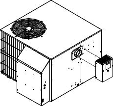
With exception of the vent terminal, this appliance is shipped completely assembled and internally wired. All fuel oil and refrigerant piping, refrigerant charge, and electrical wiring have been factory installed and inspected. At the time of installation, the unit will require connection to electric power, fuel oil supply, condensate drain, and supply and return air ductwork. In addition, the vent termination kit will need assembly. In the event of a shortage of parts or damage, refer to the Dealer Receiving and Freight Claim Procedure section of the Price Guide.
This unit uses a fan-assisted combustion system, consisting of a pressure atomizing, oil burner and combustion air blower, used to push the products of combustion through the heat exchanger system. After installation, the furnace and duct system must be adjusted to obtain a temperature rise of 50°F to 80°F through the unit. (Refer to the rating label located on side panel inside the burner compartment). The installation must conform with local codes or, in the absence of local codes, with the Standard for the Installation of Oil-Burning Equipment, NFPA 31-1997, or the latest edition, and to these instructions.
9
All installations and services must be performed by qualified service personnel.
A. Codes and Clearances:
The following items must be considered when choosing the size and location of the unit.
1.All local codes and/or regulations take precedence over the instructions in this manual and should be followed accordingly. In the absence of local codes, installation must conform to these instructions and the guidelines of the National Fire Protection Association (NFPA). Two applicable NFPA installation codes are the National Electrical Code, ANSI/NFPA 70-1999, and Standard for the Installation of Oil-Burning Equipment, NFPA 31-1997. The latest editions of these codes should be consulted.
2.The selection of a heating unit should be based on a rate of heat loss calculation for the residence according to the manuals provided by the Air Conditioning Contractors of America (ACCA) or the American Society of
Heating, Refrigeration, and Air Conditioning Engineers (ASHRAE). The heating capacity of the unit proposed for installation should meet or slightly exceed the rate of heat loss for the residence. Oversizing should not exceed 125% of the heat loss calculation.
3.When installed, this unit should be level. If possible, it should be installed in a central location, with respect to outlet registers of the supply air ductwork.
4.Definitions of "combustible" and "non-combustible" materials as presented in the 1996 version of the National Fuel Gas Code, ANSI Z223.1-1996/NFPA 70-
1996, are as follows:
a.Combustible material:
“...materials made of or surfaced with wood, compressed paper, plant fibers, or other materials that are capable of being ignited and burned. Such materials shall be considered combustible even though flameproofed, fire-retardant treated, or plastered.”
b.Non-combustible material:
“...material that is not capable of being ignited and burned; such as material consisting entirely of, or a combination of, steel, iron, brick, concrete, slate, asbestos, glass, and plaster.”
10
All installations and services must be performed by qualified service personnel.
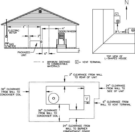
5. Table 1 lists the required minimum clearances to combustible surfaces from the outer surfaces of the appliance.
Table 1: Minimum Clearances to Combustible Materials
Model |
Top |
Side |
Rear |
Front |
Bottom |
Vent Terminal |
No. |
(in.) |
(in.) |
(in.) |
(in.) |
(in.) |
(in.) |
|
|
|
|
|
|
|
OPA |
- |
3 |
3 |
3 |
0 |
3 |
|
|
|
|
|
|
|
The minimum clearances listed in Table 1 are for fire protection purposes only. Adequate operational and service clearances must be maintained under all circumstances. A minimum of 36 inches clearance around the condenser coil should be maintained for adequate airflow to the unit. Any overhanging material or construction must not block from above the condenser fan and the vent terminal. The suggested minimum clearances for servicing the front of the unit and to all points requiring access are at least 24 inches.
Notice: Access panels for the return air filter and the blower motor are located on the rear left-hand and right-hand sides of the unit, respectively.
6.Install this unit outdoors only.
7.This appliance is approved for use as a forced air furnace with cooling unit.
8.This appliance has been designed for use with no. 2 distillate fuel (domestic heating) oil.
B.Selection of Installation Location
1.The unit should not be placed in a position where it is directly exposed to sunlight during the majority of the day. Inside corners on the southeast and southwest sides of the structure should be avoided. Heat build-up due to solar radiation in such corners would place an increased cooling load on the unit. Shaded areas on the north side of the structure are preferred.
2.The unit must be located on a level, dry surface in an area, which is free and protected from excessive drafts or wind. Mount the unit on a sturdy base at least one inch above the ground or roof surface. A poured concrete slab, or equivalent, is ideal. If concrete blocks or bricks are used, be sure to use welltamped gravel fill beneath the blocks or bricks to prevent settling.
The unit is manufactured with runner supports that raise the unit, about 1.25 inches above the mounting base, allowing air circulation beneath the metal
11
All installations and services must be performed by qualified service personnel.
surfaces. This clearance helps to promote air circulation under the base that allows the unit to be mounted on combustible materials. This clearance also helps to reduce metal corrosion caused by a buildup of moisture under the appliance.
3.The cooling system condenser must have an unrestricted supply of air for efficient cooling.
4.The cooling system fan discharges air, upward through the top grill. For this reason, this appliance should not be located under an overhang or any other obstruction to airflow that would redirect the heated discharge air back into the condenser. The appliance should be located as illustrated in Figure 1, below.
Figure 1: Selection of Appliance Installation Location
For proper and safe operation of this appliance, ensure that adequate clearances around air openings into the burner compartment and the
12

All installations and services must be performed by qualified service personnel.
condenser coil area are maintained. These openings are not to be blocked, or restricted, in any manner.
5.Measures should be taken to prevent the entry of corrosive chemicals or vapors to the combustion and ventilation air supply. Such chemicals include, but are not limited to, chlorinated and/or fluorinated hydrocarbons. These substances are found in refrigerants, aerosol propellants, dry cleaning fluids, degreasers, and removers. Other harmful compounds may come from acids, salts, bleaches, air fresheners, cements, and glues. Do not store or use these chemicals for long periods of time in close proximity to this appliance.
Vapors from such products can form corrosive compounds when burned in a flame. These compounds promote rapid corrosion of the burner, combustion chamber, heat exchanger, and the vent terminal. Rapid or excessive corrosion will significantly reduce the useful life of the appliance.
6.Refer to the following section, Venting of Combustion Products, for additional installation location restrictions.
C.Venting of Combustion Products


 : This appliance is designed to directly vent combustion products into the atmosphere through, and using only, the supplied vent terminal. Do not attempt to attach a vent connector or a vent system to, or in place of, the supplied vent terminal.
The appliance should be installed in a location such that heavy snow accumulation will not excessively restrict the flow of flue (combustion) products from the unit. The vent terminal should not be located in a position where ice buildup could block the discharge of flue products. If these conditions occur, the performance of the heating system will be adversely affected.
Choose an installation location where the vent terminal does not discharge over sidewalks, walkways, and patios. These areas may become slippery when wetted by water vapor in the flue products.
Combustion products must not be allowed to accumulate within a confined space and recirculate back into the combustion system. Recirculation of combustion products promotes poor combustion. In severe cases, it may lead to sooting of the combustion chamber and heat exchanger, or to nuisance shutdowns of the heating system.
13
All installations and services must be performed by qualified service personnel.
In addition, long term exposure of building materials to combustion products may cause discoloration of material surfaces and corrosion or degradation of materials. The preferred installation location will allow combustion products to freely escape the immediate area of the appliance and rapidly disperse into the atmosphere, without being drawn back into the appliance or a nearby structure.
To prevent combustion products from entering a structure, the vent terminal must expel combustion products away from any point of entry. The minimum acceptable distances from the vent terminal to points of entry to a building are 4 feet horizontally from, and 1 foot above, or at least 4 feet below, any window, door, or gravity air inlet into the building. And, 3 feet or more above any forced air inlet to the building located within 10 feet of the terminal.
Once the unit is installed in a suitable location, the installer must mount the vent terminal to the appliance. Two sheet metal screws are installed in the unit for this purpose. Refer to Figure 2 for a sketch of the correctly assembled vent terminal.
FIGURE 2: Vent Terminal Mounting Position
D. Condensate Drain
This appliance is equipped with a ¾ inch, female, NPT coupling for connection of a condensate line to the evaporator drain pan. A condensate removal line should be fabricated and attached to the coupling, refer to Figure 3. The condensate drain line must be pitched downward to drain properly. The drain line can also be trapped and the condensate pumped to a suitable drain. If the drain line clogs, when the air conditioner is operating, the condensate tray under the evaporator coil will fill with water. As a result, water may enter the appliance housing and the supply air ductwork to the structure.
14

All installations and services must be performed by qualified service personnel.
Figure 3: Installation of a Condensate Drainage Line on the Evaporator Coil
Condensate from the evaporator is non-corrosive and may be disposed of in any appropriate manner. The drain connection should be sealed at the appliance housing to prevent air leakage from the supply air system. Pipe sealant should be used sparingly on all male pipe threads. Always consult and conform to the requirements of local plumbing codes.
E. Oil Tank and Piping


 : All local codes and ordinances take precedence with regard to selection and installation of oil storage tank and oil supply (and return) lines. In the absence of local codes, all tanks and lines must be selected and installed according to the instructions in this manual and the Standard for the Installation of Oil-Burning Equipment, NFPA 31-1997, or the latest edition.
1.The use of black steel pipe and malleable iron fittings is recommended for all fuel oil service lines. Never use galvanized steel piping or fittings for any fuel oil lines.
2.Where practical, provide rigid supports for the piping.
3.If the piping size in a run must be reduced, use reducing couplings only. Avoid the use of reducing bushings.
4.Remove all pipe thread burrs and inspect the pipe for dirt or other foreign material prior to connecting. If present, remove any deposits in the piping and discard any excessively corroded piping.
15
All installations and services must be performed by qualified service personnel.
5.A readily accessible, design-certified, manual oil shutoff valve, with a nondisplaceable rotor member, shall be installed in the fuel oil supply piping within 6 feet of the appliance.
6.A pipe union, or flanged connection, shall be provided downstream from the manual oil shutoff valve to permit removal of the appliance oil pump. Pipe unions must be the ground joint type or flanged-jointed using a gasket resistant to the corrosive action of fuel oils.
7.Pipe dope or thread sealant design-certified to be resistant to the action of fuel oils should be used on all threaded joints. Thread sealant should only be applied to the male member of a joint. The first two threads on the end of the male member of each pipe joint should be clean and free from thread sealant.
8.Connection of the oil supply piping to the appliance should be made from the left-hand side of the burner, facing the burner compartment cover.
9.When tubing is to be used for fuel oil supply lines, use of continuous runs of heavy wall copper tubing is recommended. Avoid running tubing against any type of heating unit and across ceiling or floor joists. If possible, install the tubing under the floor.
10.Where tubing is used for fuel oil supply lines, insure the tubing contains no kinks, sharp bends, or collapsed regions where the inside cross-sectional area of the tube is greatly reduced. These will excessively reduce the flow of oil.
11.Flared fittings should be used at all tube joints, when tubing is used for fuel supply lines. Do not use compression fittings. Avoid the use of tube fittings in inaccessible locations.
Burners are equipped with a single-stage, fuel pump. This type of fuel pump, when connected with a supply line only, is satisfactory where the fuel supply is level with, or above the burner thus permitting gravity flow of oil to the burner. If the tank is above the burner, and gravity oil feed to the burner is permitted, a single line system may be used. The line should have a gradual slope downward of approximately 1/2 inch per foot, or more, from the tank to a point directly below where it is connected to the pump. Pitching the line upward toward the tank will help prevent the formation of air pockets in the line.
NOTICE: An oil safety valve or a delayed-action, solenoid valve should be installed in the oil supply line of all gravity-fed systems.
When the oil tank is located below the level of the burner, it is necessary to “lift” the oil to the burner. A return line should be connected between the fuel pump
16
All installations and services must be performed by qualified service personnel.
and tank. This requires insertion of the "by-pass" plug into the fuel pump. If the lift (vertical distance between the supply line inlet and the burner) exceeds approximately 10 feet, a two-stage pump should be installed with a return line. When a return line is used with either single or two-stage pumps, in-line air is automatically returned to the tank, making the oil pump and lines self-purging.
Underground tanks should be located outside the building. Installation of above ground tanks is permitted inside buildings, under certain conditions, as well as outside. Consult the Standard for Installation of Oil-Burning Equipment for restrictions. If permitted, connect the burner oil supply line near the base of the tank, opposite of the fill end. Connection at this point tends to flush older oil through and out of the tank. This helps to prevent the accumulation of rainwater and condensed water vapor in the tank, which can cause the tank to corrode.
If the oil supplier does not already use oil additives, it is recommended that additives be used to emulsify any water accumulation in the oil.
F. Oil Filter
It is strongly recommended that an oil filter assembly be installed in the oil supply line to the unit. Use an oil filter with the capacity to trap a 40-50 micron particle for all installations. Install the filter between the oil manual shutoff valve and the burner.
The filter cartridge should be replaced at least once a year. The filter body should be thoroughly cleaned before installing a new cartridge.
G. Burner Specifications And Performance
The appliance is supplied with two oil burner nozzles, one for the high-fire and one for the low-fire heat input rate. The model OPA has the low-fire, oil nozzle already installed in the burner by the factory. Table 2 gives the burner specifications and the estimated performance of the appliance operating under high and low fire conditions.
17
All installations and services must be performed by qualified service personnel.
Table 2: Burner Specifications and High and Low Fire Heating Performance
Heating |
Oil Pump |
Oil Flowrate |
Heat Input |
Heat Output |
Burner Model |
Air Tube |
Nozzle |
|
Mode |
Pressure |
@ Nozzle |
Rate* |
Rate** |
Number |
Combination |
Type |
|
(PSIG) |
(GPH) |
(BTUH) |
(BTUH) |
|||||
|
|
|
|
|||||
|
|
|
|
|
|
|
|
|
High Fire |
130 |
0.75 |
105,000 |
85,000 |
|
|
Simplex, 80 |
|
|
|
|
|
|
AFG-TP1501 |
AF35 BOSS |
deg., hollow |
|
|
|
|
|
|
||||
Low Fire |
120 |
0.6 |
85,000 |
67,000 |
|
|
cone |
|
|
|
|
|
|
|
|
|
*Based on #2 fuel (domestic heating) oil having higher heating value of 140,000 BTU per gallon.
**Based on an assumed steady state, thermal efficiency of 80%.
For more specific burner information, consult the Model AFG Oil Burner Instruction Manual or contact Thermo Products, LLC. P.O. Box 217, North
Judson, IN 46366. Phone no. 574-896-2133.
18
All installations and services must be performed by qualified service personnel.
H. Airflow Requirements and Sizing of Duct Work
The duct system must be sized and installed by a qualified installer or service person, following the design standards of the Air Conditioning Contractors of
America (ACCA) or the American Society of Heating, Refrigeration, and Air
Conditioning Engineers (ASHRAE). This furnace has been designed to operate against a maximum external static pressure of 0.4 in. W.G. This is equivalent to .2 in. W.G. supply and .2 in. W.G. return pressure drops.
1.Supply and return air ducts have to be furnished by the installer and run between the appliance, which must be installed outdoors, and the interior of the structure the appliance serves. These ducts must be sealed to the casing of the appliance.
2.To reduce the transmission of vibration and noise to the duct system and to reduce flexure of the duct system due to thermal expansion and contraction, it is recommended that flexible joints be installed at the supply and return duct connections to the unit.
3.The return air duct system must equal the supply air duct system in the flow capacity (CFM) for a given pressure drop. Use a supplier's catalog for proper sizing of outlet and return air registers and grills to ensure that they meet the flow requirements of the run to which they are connected.
4.The duct system shall be sized to provide the maximum air flowrate (CFM) required of the installation. Two common rules for determining minimum airflow in heating and cooling systems follow:
a.For heating, 14 CFM of airflow are required per 1000 BTU/hr of heat output, based on steady state operation and a 50° to 80° temperature rise.
b.For cooling, 400 CFM of airflow are required per ton of air conditioning.
(For reference, a ton of A/C = 12,000 BTU/hr removed from the space.)
Refer to Example 1, in Appendix B: Calculations of this manual, for a sample calculation of how to determine the required minimum air flowrate.
5.Duct sizing is based upon both air velocity and pressure drop considerations.
When possible, current practice favors designing ductwork for lower air velocities. (For residences, a maximum air velocity of 800 FPM is suggested.) This results in quieter duct systems, systems which require less fan power
(reduced operating costs), and less carefully constructed ductwork (lower initial costs).
However, lower air velocities also result in larger duct sizes than necessary at higher velocities. In some cases, space restrictions may limit the ductwork to smaller than optimal sizes.
19
All installations and services must be performed by qualified service personnel.
6. The following method can be used to size ductwork when air velocities are low to moderate.
a.Using a floor view of the residence, determine, or layout, the locations of the supply registers and the return air grills. (Generally, supply registers should be located close to sources of heat loss, i.e. windows and doors, around the perimeter of the building. Return grills should be located in central positions as far away from the supply registers as practical.)
b.Find a location for the appliance outside the building that minimizes the amount of ducting required to connect the appliance to the supply and return air duct systems. Consider issues of access to the oil supply and electrical service, required service and venting clearances, exposure to sunlight, and operating noise when selecting this location.
c.Plan an efficient layout for the ductwork connecting each of the supply air registers in the supply system to the unit. Plan and layout ductwork connecting each of the return air grills in the return system to the unit.
Measure or estimate the length of duct between each register and grill.
d.Select values for the airflow through each register and grill.
e.Select values for the pressure drops of both the supply and return air systems. Each branch of the supply (or the return) air system will have this pressure drop. The total pressure drop of the supply and return air systems added together cannot exceed the maximum external static pressure that can be supplied by the appliance blower.
f.Determine the required flowrate for each branch of the supply and return air systems. The total air flowrate, by adding the air flowrate of each branch of the supply system, must equal the minimum required air flowrate (refer to part 3, above). Likewise, the air flowrate of each of the branches of the return air system must sum to the required minimum flowrate.
g.Using the selected air flowrates for each component of the duct system and manufacturer’s literature, or published literature on duct system pressure drops, the pressure drop for each component in the duct system can be estimated.
(Chapter 32 of the ASHRAE Handbook – Fundamentals is an excellent source of duct system design principles and pressure drop data.)
Conversely, for a specified type of fitting, it is also possible to determine the required size or diameter of the component for a specified pressure drop and flowrate.
20
All installations and services must be performed by qualified service personnel.
h.The resistance of the take-off and the outlet register (or return grill) should then be summed together to determine the total pressure drop for each branch. This value should be close to the assumed value for the pressure drop of the system. If it is not close, then flowrates for each branch must be adjusted, or the design of the duct system must be altered, to give the proper pressure drops. Usually, the cross-sectional area of the ductwork should be changed in order to adjust the pressure drop to a suitable value.
Refer to Example 2, in Appendix B: Calculations of this manual, for a sample calculation of how to use this method for sizing the supply side ductwork for a residence.
Table 3 shows the air handling capacities of 100-ft. lengths of circular and rectangular ductwork based on a 0.1 in. W.G. static pressure drop. The first column to the right is the air flowrate and the second is the required diameter for a circular duct. The third column is the required cross-sectional area of the duct and the other columns to the left are rectangular ducts with sufficient cross-sectional area to handle the flow at the specified pressure drop. [For lengths of ductwork less than 100 ft., simply multiply 0.1 in. W.G. by the ratio of the actual duct length (in feet) over 100 ft. for the approximate pressure drop.] Use the supplier’s catalog for proper sizing of outlet air registers and return air grills to insure that they provide the required flowrate at the desired pressure drop.
21

All installations and services must be performed by qualified service personnel.
Table 3: Suggested Duct Sizes for Homes, Quiet Offices, Or Similar Installations
(Based on a 0.1 in. W.G. static pressure drop per 100 ft. of duct.)
7.The supply and return air ducts, or flexible joints, should be carefully secured and sealed to the appliance housing to prevent air leakage from, or into, the duct system. For best performance, insulate the outside surfaces of the ducts to reduce heat loss from, or heat gain to, the ducts. The insulation system should be carefully selected and installed to minimize water and moisture absorption by the insulation.
22

All installations and services must be performed by qualified service personnel.
8.As a final step in the installation, the appliance must be adjusted to deliver a temperature rise within the range of 50° to 80°F. Adjust the blower motor speed to obtain a temperature rise within the acceptable range. The required blower speed will depend on the airflow resistance of a supply and return air duct systems.
I.Air Filters
1.Filter Installation
This OPA unit has been factory supplied with a high quality, re-usable filter rated for air velocities up to 600 ft/min.
2.Use of non-Thermo Pride Filters or Retention Means


 : Failure to comply with minimum filter installation requirements may affect the performance and/or void the warranty on this unit.
If a method other than Thermo Pride filter racks is selected for retention of the filter and/or use of a different filter type is desired, refer to Table 4 for minimum sizing guidelines for selecting filter for the unit.
Table 4: Minimum Required Filter Area (in square inches)
|
Maximum |
|
Model Number |
|
|
Filter Type |
Air Velocity |
|
|
||
|
(ft/min) |
OPA24 |
OPA30 |
OPA36 |
OPA42 |
*Thermo Products |
|
|
|
|
|
Supplied |
600 |
192 |
240 |
288 |
336 |
Permanent |
|
|
|
|
|
Standard |
500 |
230 |
288 |
346 |
403 |
Permanent |
|
|
|
|
|
Disposable |
300 |
384 |
480 |
576 |
672 |
The Thermo Products supplied filter can be cut to size to fit other filter retention systems as long as the minimum size requirement is met.
NOTICE: Any internal stiffeners used in the filter must not be removed, although they can be cut to size as needed.
23

All installations and services must be performed by qualified service personnel.
J. Electrical Wiring


 : This appliance must be grounded in accordance with local codes, or in the absence of local codes, with the National Electrical Code, ANSI/NFPA 70-1999, or the latest edition.


 : Waterproof type connectors must be used when connecting electrical power and control wiring to the unit to prevent moisture from being drawn into the unit during operation.
All wiring must conform to the provisions of local codes or, in the absence of local codes, with the provisions of the National Electrical Code, ANSI/NFPA 70-1999, or the latest edition, and this instruction manual.
This appliance requires 208-240 VAC, 60 Hz, single-phase power. Refer to Table 5 for typical electrical current draws of the individual appliance motors, recommended sizes for over-current and short circuit devices, and minimum recommended field wiring sizes. Electrical service must be brought to the unit from a circuit breaker, or fused disconnect switch, in accordance with local codes. The disconnecting switch must be located reasonably close to and within sight of the unit.
Three-wire service, two “hot” leads (L1 and L2) and a neutral (N), plus a ground conductor, is required. Connect power to the appliance control system at the junction box in the burner compartment. (A knockout fitting is provided on the exterior of the burner compartment for this purpose.) A ground wire must be connected to the grounding lug, or screw, marked “Equipment Ground”, in the junction box.
Field wiring of power circuits to the appliance should consist of copper conductors rated for at least 240 VAC with an insulation temperature rating of at least 75°C temperature rise. Depending upon code requirements, rigid or flexible conduit is recommended, and may be required. Connect the electric power supply as shown in the wiring diagram located on the inside of the burner compartment cover, or in this manual. The cooling system operates on 208-240
VAC electric power, from supply wires L1 and L2. The heating system operates on 120 VAC electric power, from supply wires L1 and N.
24

All installations and services must be performed by qualified service personnel.
Typically, control wiring between the outdoor appliance and the indoor thermostat, and if used, electronic air cleaner or humidifier, will be required. Field wiring of control circuits should consist of copper conductors rated for at least
240 VAC with an insulation temperature rating conforming to Type T wire, 35°C temperature rise. Depending upon code requirements, rigid or flexible conduit is recommended, and may be required. Make connections between the thermostat, and electronic air cleaner or humidifier (if used), and the fan control module, inside the burner compartment. Consult the wiring diagram for the appropriate connection points on the thermostat and the fan control module.
Table 5: Typical Electrical Requirements for Various OPA Models
|
|
Compressor |
Compressor |
Condenser |
Supply/Return |
Oil Burner |
Maximum |
Recommended |
Minimum |
|
|
Potential/Frequency |
Running |
Locked |
Fan Full |
Assembly |
Time Delay |
Time Delay |
Recommended |
||
Model |
Load |
Rotor |
Load |
Air Blower Full |
Full Load |
Type Fuse |
Type Fuse or |
75 deg. C. |
||
/No. of Phases |
Current |
Current |
Current |
Load Current |
Current |
or Inverse |
Inverse Time |
Copper Power |
||
|
(V/Hz/Ph) |
(Amps) @ 115 |
Time Circuit |
|||||||
|
|
(Amps) @ |
(Amps) @ |
(Amps) @ |
VAC |
(Amps) @ |
Breaker Size |
Circuit Breaker |
Wiring Size |
|
|
|
200 VAC |
200 VAC |
200 VAC |
115 VAC |
Size (Amps) |
(AWG) |
|||
|
|
|
|
|
|
|
(Amps) |
|
|
|
OPA24 |
|
9.3 |
47 |
|
|
|
25 |
25 |
12 |
|
OPA30 |
208-240/60/1 |
13.6 |
61 |
2.1 |
11 |
5.8 |
35 |
30 |
10 |
|
OPA36 |
15 |
73 |
40 |
35 |
8 |
|||||
|
|
|
|
|||||||
OPA42 |
|
18.4 |
95 |
|
|
|
50 |
35 |
8 |
Wire size selections in Table 5 are based upon Table 310-16 of the National Electrical Code for three copper conductors, with insulation rated for 75 degrees Celsius, contained in raceway at 30 degrees Celsius. For other wire insulation temperature ratings and ambient conditions, refer to the National Electrical Code for the minimum wire sizing requirements.
NOTICE: Before the unit is started, the installer and/or electrician must check the following items.
1.Check every electrical connection of “push-on” or “screw-on” type terminals to ensure that all wires and wire connectors are firmly secured. A loose terminal can cause poor flow of electrical power to motors and to the refrigeration compressor. This may result in very high current draws by these components.
If great enough, high current draw will cause blown fuses, burned wires and contactor points, and pre-mature motor or compressor failure. Each electrical connection has been factory checked, however, connections may loosen, due
to vibration, while the appliance is in transit. Please be certain that all electrical connections remain tight.
2. Review wiring diagram for proper routing and connection of all field wiring.
25
All installations and services must be performed by qualified service personnel.
3.All wiring sizes must comply with local codes or the National Electrical Code. To minimize voltage drop to the appliance, the next larger size wire should be used when long wiring runs, in excess of 100 ft., are employed. Refer to the wiring diagrams when wiring or servicing.
NOTICE: Proper operation of the heating section of this unit depends upon correctly connecting the electrical power source. The hot leg, L1, of the supply circuit must be connected to the black line lead and the neutral leg, N, to the white line lead in the burner compartment junction box. All ungrounded circuit conductors must be broken by the disconnecting switch to prevent the hazard of electrical shock when servicing this appliance.
In the event a circuit breaker trips or a fuse blows as a result of the operation of this appliance, investigate the appliance electrical system to determine the cause. Correct any electrical faults and abnormal conditions before putting the unit back into operation. Do not put in a larger fuse and do not exceed maximum fuse size listed on the rating label in order to temporarily “fix” the problem. The rating label is located on the inside of the burner compartment cover.
The appliance control system contains a 15 amp. time-delay type fuse to protect the heating system control circuitry. The control fuse is located within the junction box, which is located in the burner compartment. In the event the fuse blows, replace the fuse with one of equivalent type and rating.
1.Electronic Air Cleaner (EAC) and Humidifier Installation
The standard control system for the appliance does not have the ability to directly control the operation of an electronic air cleaner or a humidifier. If these devices are used, a means to initiate and discontinue their operation must be provided external to the accessory if such means is not provided internally. Typically, an airflow sensing control is installed in the duct system to determine operation of the furnace and automatically activate (and also deactivate) the EAC or humidifier.
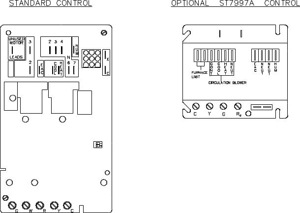
If the control system contains the Honeywell brand model ST7997 electronic fan timer, this unit has designated terminals to control the operation of an electronic air cleaner and/or humidifier. These terminals provide line voltage for the control of these accessories, refer to Figure 4.
26
All installations and services must be performed by qualified service personnel.
Figure 4: The Fan Control Module
NOTICE: It is important to confirm that the operating voltage of the humidifier or EAC being installed matches the output of this control. If not, a field supplied relay or transformer may be necessary to provide the proper control and supply voltage for the accessory being installed. Refer to the manufacturer’s instructions for the humidifier or EAC for additional information.
27
 Loading...