

Page 1
ALL INSTALLATIONS AND SERVICE MUST BE PERFORMED BY QUALIFIED SERVICE PERSONNEL.
INSTALLATION INSTRUCTIONS FOR
CONCENTRIC VENT KIT AOPS7483 & DUAL PIPE FLASHING KIT AOPS7484
ELECTRIC SHOCK HAZARD/FIRE AND/OR EXPLOSION HAZARD.
Failure to carefully read and follow all instructions in these instructions could result in death,
personal injury, property damage and/or furnace malfunction.
Installation or repairs made by unqualified persons could result in hazards to you and others.
Installation MUST conform with local codes or, in the absence of local codes, with codes of the
country having jurisdiction.
The information contained in these instructions is intended for use by a qualified service
technician familiar with safety procedures and equipped with the proper tools and test
instruments.
ELECTRIC SHOCK HAZARD/FIRE AND/OR EXPLOSION HAZARD.
Failure to follow this warning could result in death, personal injury, property damage and/or
equipment damage.
Turn OFF gas supply at manual gas valve before turning OFF electric power supply and
starting installation.
Turn OFF electric power supply at disconnect switch or service panel before starting
installation.
CARBON MONOXIDE POISONING, AND PROPERTY DAMAGE HAZARD.
Failure to follow this warning could result in death, personal injury, property damage and/or
equipment damage.
This kit is to be used for terminating condensing Category IV vent furnaces. DO NOT use kit
to terminate Category I, II, or III vent furnaces.
MG-507
ECN 5059-MA
- 1 -
Page 2
ALL INSTALLATIONS AND SERVICE MUST BE PERFORMED BY QUALIFIED SERVICE PERSONNEL.
AOPS7483 Kit contents:
Item Qty
Concentric Vent 1
Flashing, single pipe 2
Hose clamp 2
Fitting 4x3 (Fernco) 1
Instructions 1
CONNCENTRIC VENT
AOPS7484 Kit contents:
Item Qty
Flashing, dual pipe pipe 2
Hose clamp 4
Instructions 1
MG-507
ECN 5059-MA
- 2 -
Page 3
ALL INSTALLATIONS AND SERVICE MUST BE PERFORMED BY QUALIFIED SERVICE PERSONNEL.
INSTALLING CONCENTRIC VENT UTILIZING EXISTING ROOF JACK AS A CHASE.
1. Required kit: AOPS7483
2. Type installation: Vertical through the roof
3. Remove top cap and bird screen from roof jack. If present, remove 4” diameter inner
pipe shield and fold over vertical tabs inside flue pipe.
4. Determine vertical height dimension (DIM-A) of current roof jack, see FIG-2. THIS
DIMENSION IS IMPORTANT. If this dimension is less than 14-7/8”, skip to step 6. If
dimension is greater than 14-7/8”, the 3” and 2” PVC pipes in the concentric vent
assembly will need to be replaced with longer pipes to ensure proper installation.
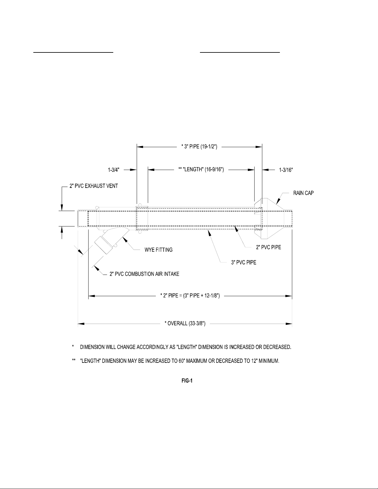
5. To extend the concentric vent assembly, the two pipes supplied in the kit will need to be
replaced with single piece (no coupling connections allowed) same diameter solid core,
field supplied SDR-26 PVC (ASTM D2241) pipe. See FIG-1, FIG-3 & FIG-4 for
calculating new pipe cut lengths.
UNIT OPERATION HAZARD.
Failure to follow this caution may result in intermittent unit operation.
Do not use field supplied couplings to extend the pipes. Airflow restriction will occur and the
furnace pressure switch may cause intermittent operation.
6. Place Fernco Fitting on end of 3” pipe leaving 1 ¼” of pipe exposed above fitting for rain
cap, see FIG-3. Tighten clamp.
7. Affix rain cap to 2” pipe with either PVC cement or a field supplied stainless steel screw,
see FIG-4.
CARBON MONOXIDE POISONING, FIRE AND EXPLOSION HAZARD.
Failure to follow this warning could result in death, personal injury and/or property damage.
When using the alternate screw assembly method, drill a clearance hole in the rain cap and a
pilot hole in the vent pipe for screw size being used. Failure to drill adequate holes cause
cracking o the PVC components, allowing flue gasses to be recirculated.
- 3 -
Page 4
ALL INSTALLATIONS AND SERVICE MUST BE PERFORMED BY QUALIFIED SERVICE PERSONNEL.
8. Drop 3” pipe assembly (FIG-3) thru 4” flue opening of roof jack, seat Fernco fitting firmly
on roof jack flue pipe and tighten clamp.
9. Drop 2” pipe assembly (FIG-4) thru 3” pvc pipe, seat rain cap tightly on end of 3” pvc
pipe.
CARBON MONOXIDE POISONING, FIRE AND EXPLOSION HAZARD.
Failure to follow this warning could result in death, personal injury and/or property damage.
Do not operate the furnace with the rain cap removed as recirculation of the flue gases may
occur. Water may also collect inside the larger combustion air pipe and flow to the burner
enclosure.
10. At this point the WYE fitting can be applied using PVC cement to affix it to the 3”
diameter pipe, see FIG-5.
11. Using field supplied PVC pipe and elbows connect the center vent pipe on the WYE
fitting to the exhaust vent pipe on the furnace and the 45° air intake pipe on the WYE
fitting to the combustion air intake pipe on the furnace. PVC cement all joints except for
the final connection to the furnace. Use radiator hose fittings and clamps included with
furnace to make final connection, see FIG-5.
- 4 -
Page 5

ALL INSTALLATIONS AND SERVICE MUST BE PERFORMED BY QUALIFIED SERVICE PERSONNEL.
- 5 -
Page 6

ALL INSTALLATIONS AND SERVICE MUST BE PERFORMED BY QUALIFIED SERVICE PERSONNEL.
INSTALLING CONCENTRIC VENT THRU THE ROOF USING 3” FLASHING PLATES.
1. Required kit: AOPS7473
2. Type installation: Thru the roof.
3. If a roof jack is in place it will need to be removed.
4. Install one of the 3” flashing plates on the roof covering the existing opening of the
previous roof jack or if no roof jack was in place previously, a 3 ½” to 4” diameter hole
will need cut in roof. Then place flashing plate over hole. Plate should be secured with
some type of roofing fasteners and an appropriate type of roof caulk or sealant to
ensure no leakage after installation.
5. Determine vertical height dimension (DIM-D) of ceiling surface to rain cap, see FIG-8. If
this dimension is less than 16-9/16” skip to step 7. If dimension is greater than 16-9/16”
the 3” and 2” PVC pipes in the concentric vent assembly will need to be replaced with
longer pipes to ensure proper installation.
6. To extend the concentric vent assembly, the two pipes supplied in the kit will need to be
replaced with single piece (no coupling connections allowed) same diameter solid core,
field supplied SDR-26 PVC (ASTM D2241) pipe. See FIG-1, FIG-6 & FIG-7 for
calculating new pipe cut lengths.
UNIT OPERATION HAZARD.
Failure to follow this caution may result in intermittent unit operation.
Do not use field supplied couplings to extend the pipes. Airflow restriction will occur and the
furnace pressure switch may cause intermittent operation.
7. Drop 3” pipe (FIG-6) thru hole leaving the required length of pipe above roofline for
snow level clearance. Seal with RTV sealant where pipe and flashing meet and clamp
tightly with factory supplied clamp, see FIG-8.
8. Affix rain cap to 2” pipe with either PVC cement of a field supplied stainless steel screw,
see FIG-7.
- 6 -
Page 7

ALL INSTALLATIONS AND SERVICE MUST BE PERFORMED BY QUALIFIED SERVICE PERSONNEL.
CARBON MONOXIDE POISONING, FIRE AND EXPLOSION HAZARD.
Failure to follow this warning could result in death, personal injury and/or property damage.
When using the alternate screw assembly method, drill a clearance hole in the rain cap and a
pilot hole in the vent pipe for screw size being used. Failure to drill adequate holes cause
cracking o the PVC components, allowing flue gasses to be recirculated.
9. Drop the 2” pipe assembly (FIG-7) thru the 3” pipe, seat rain cap tightly on end of 3” pvc
pipe.
CARBON MONOXIDE POISONING, FIRE AND EXPLOSION HAZARD.
Failure to follow this warning could result in death, personal injury and/or property damage.
Do not operate the furnace with the rain cap removed as recirculation of the flue gases may
occur. Water may also collect inside the larger combustion air pipe and flow to the burner
enclosure.
10. Install ceiling flashing plate over the protruding vent assembly in ceiling. Secure with
screws or an appropriate fastener, see FIG-8.
11. Clamp and seal 3” pipe to flashing plate with factory supplied clamp, see Fig-8.
12. At this point the WYE fitting can be applied using PVC cement to affix it to the 3”
diameter pipe, see FIG-8.
13. Using field supplied PVC pipe and elbows connect the center vent pipe on the WYE
fitting to the exhaust vent pipe on the furnace and the 45° air intake pipe on the WYE
fitting to the combustion air intake pipe on the furnace. PVC cement all joints except for
the final connection to the furnace. Use radiator hose fittings and clamps included with
furnace to make final connection, see FIG-8.
- 7 -
Page 8

ALL INSTALLATIONS AND SERVICE MUST BE PERFORMED BY QUALIFIED SERVICE PERSONNEL. ALL INSTALLATIONS AND SERVICE MUST BE PERFORMED BY QUALIFIED SERVICE PERSONNEL.
- 8 -
- 8 -
Page 9

ALL INSTALLATIONS AND SERVICE MUST BE PERFORMED BY QUALIFIED SERVICE PERSONNEL.
INSTALLING CONCENTRIC VENT KIT OUT SIDE WALL.
1. Determine best location for horizontal (sidewall) termination kit. Be sure to consider
possible damage from vapor to plants shrubs, other equipment and building materials.
Also possible damage to the terminal from foreign objects and the possible wind effect
of re-circulated flue gas.
2. Cut one 3-1/2” to 4” diameter hole for the concentric vent kit through the structure.
3. Determine horizontal length dimension (DIM-G) of WYE fitting to rain cap, see FIG-11.
This dimension may decreased to a minimum of 12” or increased to a maximum of 60”.
4. To extend the concentric vent assembly, the two pipes supplied in the kit will need to be
replaced with single piece (no coupling connections allowed) same diameter solid core,
field supplied SDR-26 PVC (ASTM D2241) pipe. See FIG-1 for calculating new pipe cut
lengths.
UNIT OPERATION HAZARD.
Failure to follow this caution may result in intermittent unit operation.
Do not use field supplied couplings to extend the pipes. Airflow restriction will occur and the
furnace pressure switch may cause intermittent operation.
5. Affix the WYE fitting to the large 3” diameter pipe with PVC cement, see FIG-9.
6. Affix rain cap to 2” pipe with either PVC cement or a field supplied stainless steel screw,
see FIG-10.
CARBON MONOXIDE POISONING, FIRE AND EXPLOSION HAZARD.
Failure to follow this warning could result in death, personal injury and/or property damage.
When using the alternate screw assembly method, drill a clearance hole in the rain cap and a
pilot hole in the vent pipe for screw size being used. Failure to drill adequate holes cause
cracking o the PVC components, allowing flue gasses to be recirculated.
7. Install the 3” pipe assembly (FIG-9) through the structure’s hole leaving the required
length of pipe outside of wall to ensure installation clearances are maintained. Secure
with field supplied strap to prevent movement in sidewall, use appropriate caulk or
sealant to ensure no leakage around 3” pipe after installation, see FIG-11.
- 9 -
Page 10

ALL INSTALLATIONS AND SERVICE MUST BE PERFORMED BY QUALIFIED SERVICE PERSONNEL.
8. Apply PVC cement to pipe end of the 2” pipe assembly (FIG-10) and slide thru 3” pipe,
seating 2” pipe in WYE fitting internal socket and rain cap tightly on end of 3” pvc pipe,
see FIG-11.
CARBON MONOXIDE POISONING, FIRE AND EXPLOSION HAZARD.
Failure to follow this warning could result in death, personal injury and/or property damage.
Do not operate the furnace with the rain cap removed as recirculation of the flue gases may
occur. Water may also collect inside the larger combustion air pipe and flow to the burner
enclosure.
9. Using field supplied PVC pipe and elbows connect the center vent pipe on the WYE
fitting to the exhaust vent pipe on the furnace and the 45° air intake pipe on the WYE
fitting to the combustion air intake pipe on the furnace. PVC cement all joints except for
the final connection to the furnace. Use radiator hose fittings and clamps included with
furnace to make final connection, see FIG-11.
- 10 -
Page 11

ALL INSTALLATIONS AND SERVICE MUST BE PERFORMED BY QUALIFIED SERVICE PERSONNEL.
- 11 -
Page 12

ALL INSTALLATIONS AND SERVICE MUST BE PERFORMED BY QUALIFIED SERVICE PERSONNEL.
INSTALLING TWIN 2” DIAMETER PVC PIPES THRU THE ROOF WITH 2” HOLE
FLASHING PLATES.
1. Required kit: AOPS7484
2. Type installation: Thru the roof
3. The inlet of the combustion air intake shall be a minimum of 12” above highest
anticipated snow level, see FIG-12.
4. The exhaust vent outlet must be installed a minimum of 12” above the air intake
inlet, see FIG-12.
5. Where exposed to prevailing winds, the combustion air intake shall be installed
upwind of the vent outlet, see FIG-12.
6. The 2” flashing plates are to be used to cover both the opening in roof and ceiling.
7. Remove existing roof jack to run the 2” PVC pipes thru the roof or a hole of
diameter needs to be cut in roof and ceiling to run the PVC pipes.
8. Affix one of the flashing plates to the roof covering the existing opening or the newly
cut opening. Plate should be secured with roofing fasteners and an appropriate type
of roof caulk or sealant to ensure no leakage after installation.
9. Drop the field supplied 2” PVC pipes thru the flashing holes. Seal with RTV type
sealant and clamp securely with factory supplied clamps, see FIG-12.
10. Place ceiling flashing plate over the ceiling opening and the two 2” PVC pipes.
Secure with screws or an appropriate fastener, clamp securely with factory supplied
clamps, see FIG-12.
11. Using field supplied PVC pipe and elbows connect the 2” PVC vent pipe to the
exhaust vent pipe on the furnace and the 2” PVC air intake pipe to the combustion
air intake pipe on the furnace. PVC cement all joints except for the final connection
to the furnace. Use radiator hose fittings and clamps included with furnace to make
final connection, see FIG-12.
- 12 -
Page 13

ALL INSTALLATIONS AND SERVICE MUST BE PERFORMED BY QUALIFIED SERVICE PERSONNEL.
- 13 -
 Loading...