

Thermo Pride CLHS1-050P36N, CLHS1-075T42N, CLHS1-075P42N, CLHX1-050E36N, CLHX1-075E42N Installation And Operation Manual
...Page 1
CONDENSING GAS FURNACE
INSTALLATION AND OPERATION MANUAL
SINGLE STAGE TWO STAGE
CLHS1-050P36N CLHS1-050T36N CLHX1-050E36N
CLHS1-075P42N CLHS1-075T42N CLHX1-075E42N
CLHS1-100P48N CLHS1-100T48N CLHX1-100E48N
CLHS1-125P60N CLHS1-125T60N CLHX1-125E60N
PLEASE READ THESE INSTRUCTIONS PRIOR TO INSTALLATION, INITIAL FIRING, AND BEFORE
PERFORMING ANY SERVICE OR MAINTENANCE. THESE INSTRUCTIONS MUST BE LEFT WITH THE
HOMEOWNER AND SHOULD BE RETAINED FOR FUTURE REFERENCE BY QUALIFIED SERVICE
PERSONNEL.
BOX 217
NORTH JUDSON, IN 46366
PHONE: (574) 896-2133
MG-1041
ECN 5441-MA 160425
THERMO PRODUCTS, LLC.
MADE IN USA
Page 2

All installations and services must be performed by qualified service personnel.
INDEX
SECTION BEGINNING PAGE
I. SAFETY INFORMATION 3
II. FURNACE SPECIFICATIONS 8
A. CLHS1 SERIES (SINGLE STAGE, PSC BLOWER MOTOR) 8
B. CLHS1 SERIES (SINGLE STAGE, CONSTANT TORQUE MOTOR) 9
C. CLHX1 SERIES (TWO STAGE, ECM BLOWER MOTOR) 10
D. INSTALLATION PARTS PACKAGES - CLHS1 11
E. INSTALLATION PARTS PACKAGES - CLHX1 11
III. GENERAL INSTALLATION 12
A. CODES AND CLEARANCES 12
B. FURNACE LOCATION 13
C. REPLACING EXISTING FURNACE FROM A COMMON VENT 14
D. GENERAL REQUIREMENTS FOR VENTING 14
E. SIDEWALL VENTING 16
F. CONNECTING FURNACE TO ROOF VENT / INTAKE TERMS. 20
G. CONNECTING FURNACE TO VENT / INTAKE TERMS. 21
H. CONDENSATE DRAIN LINE & TRAP ASSY. 23
I. GENERAL GAS PIPING 27
J. REQUIREMENTS & SIZING OF DUCTWORK 28
K. FILTERS 30
L. WIRING 31
M. ADDITIONAL FEATURES 35
IV. STARTING THE UNIT 36
A. SEQUENCE OF OPERATIONS 36
B. INITIAL START-UP 37
C. ADJUSTMENT OF BTU INPUT RATE 38
D. BURNER ADJUSTMENT 40
E. FURNACE CHECKOUT PROCEDURE 40
V. INSTALLER’S INSTRUCTIONS TO USER 41
VI. TROUBLESHOOTING 41
APPENDIX
A. REPLACEMENT PARTS LIST 47
B. WIRING DIAGRAMS 51
C. SPEED SPECIFICATIONS 54
2
Page 3
All installations and services must be performed by qualified service personnel.
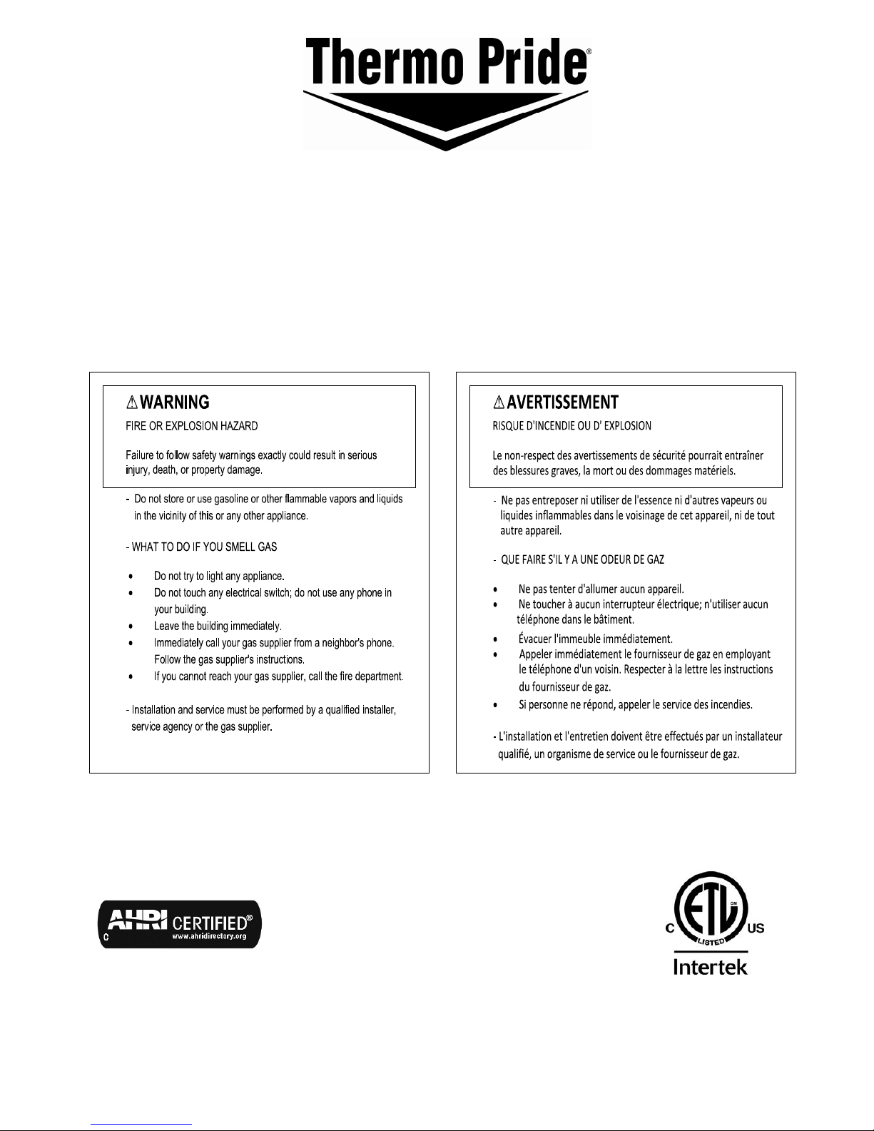
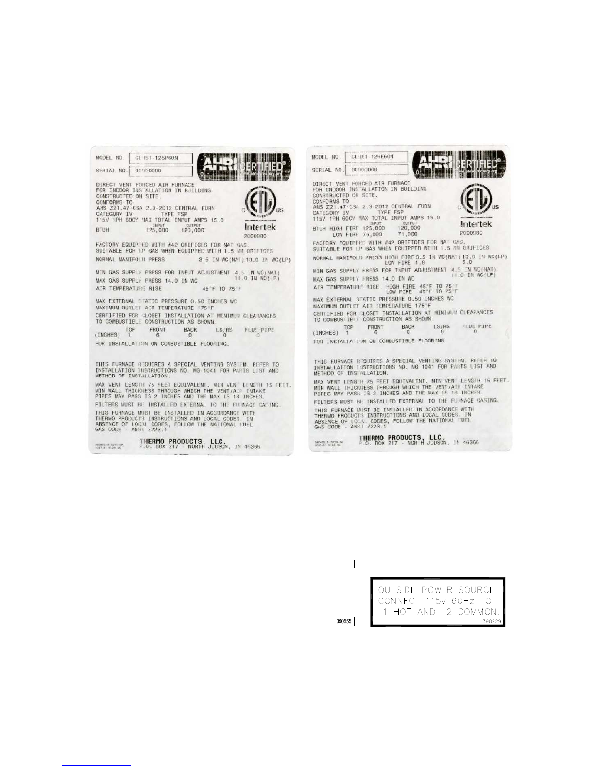
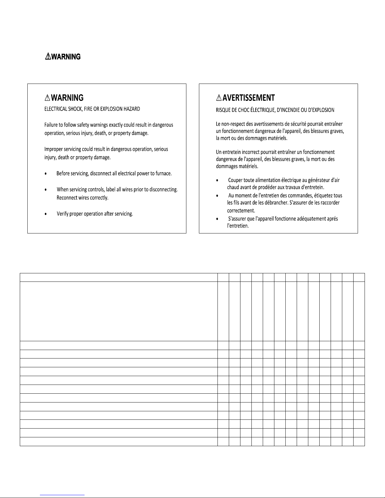
I. SAFETY INFORMATION
This and the following page contain reproductions of the various warning and instruction labels placed on the
Thermo Pride Condensing Gas Furnaces. Please read and comply with the contents of these labels.
THIS FURNACE MUST BE INSTALLED SO THERE
ARE PROVISIONS FOR VENTILATING AIR.
CETTE CHAUDIÈRE DOIT ÊTRE INSTALLÉE DE
MANIÈRE À ASSURER UN AIR DE VENTILATION.
3
Page 4
All installations and services must be performed by qualified service personnel.
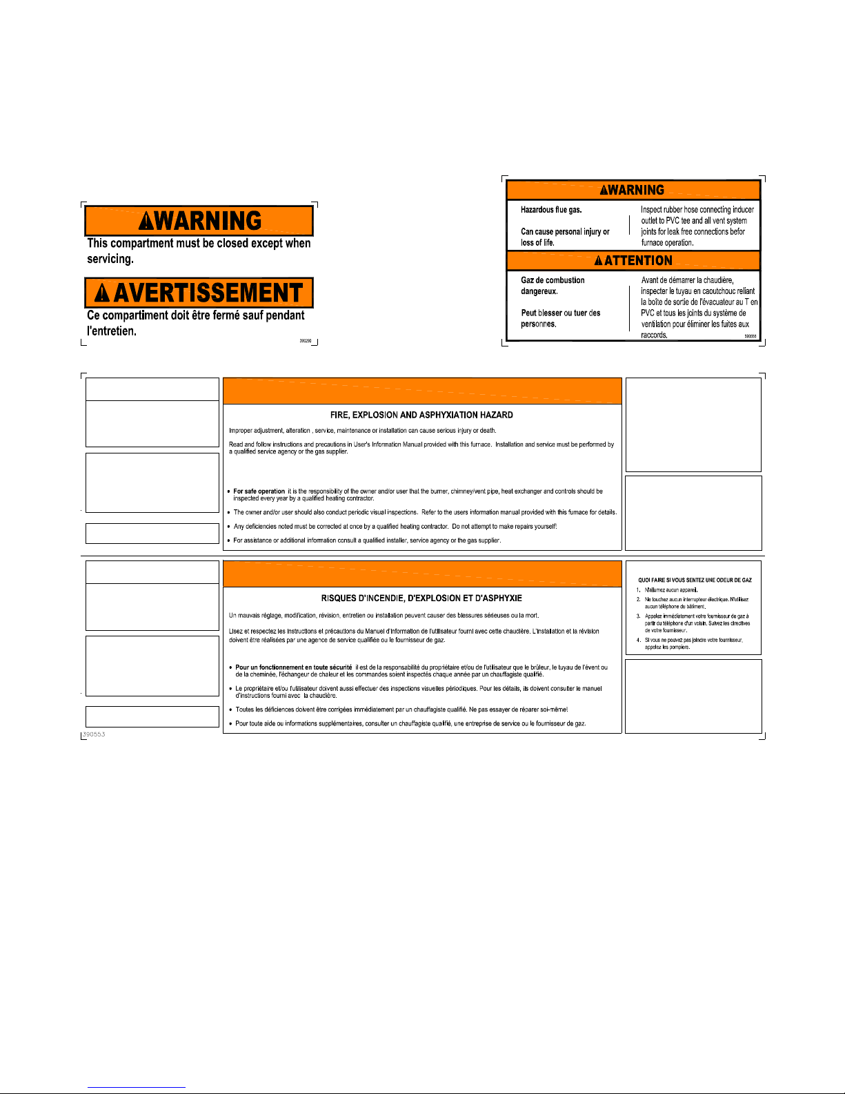
This and the previous page contain reproductions of the various warning and instruction labels placed on the Thermo
Pride Condensing Gas Furnaces. Please read and comply with the contents of these labels.
CAUTION
Moving parts.
Can cause severe personal injury.
Shut off furnace before removing this panel.
Filter maintenance: When it becomes
necessary to replace or wash filter remove
the dirty filter from the racks provided and
wash or replace with identical new filters.
Do not remove this label
b
WARNING
SPECIAL HOMEOWNERS INSTRUCTIONS
FOR YOUR SAFETY
WHAT TO DO IF YOU SMELL GAS:
1. Do not try to light any app liance.
2. Do not touch any electrical switch; do not use any
phone in your building.
3. I mmediately call your gas supplier from a
neighbor's phone. Follow the gas supplier's
instructions.
4. If you c annot reach your gas supp lier; call the fire
department.
b
WARNING
FIRE AND E XPLOSION HAZARD
Can result in serious injury or death.
Do not store or use g asoline or other flammable vapors
and liquids in the vicini ty of this or any other appliance.
Storage of or use o f gasoline or other flammable vapors
or liquids in the vicinity of this or any appliance can result
in serious injury or death.
AVERTISSEMENT
Les pièces mobiles peu vent blesser gravement des
personnes.
Arrêter la chaudière avant d'enlever ce panneau.
Maintenance des filtres : Quand il le faut,
retirer les filtres encrassés de leurs boîtiers,
les laver ou les remplacer par des filtres
neufs identiques.
Ne pas enlever cette étiquette
b
ATTENTION
INSTRUCTIONS SPÉCIALES POUR LES PROPRIÉTAIRES
POUR VOTRE SÉCURITÉ
b
AVERTISSEMENT
RISQUES D'INCENDIE ET D'E XPLOSION
Peuvent entraîn er des blessures sérieuses ou la mort.
Ne pas stocker ou u tiliser d'essence ni autres vapeurs ou
liquides inflammables à proximité de cet appareil ou tout
autre dispositif.
Le stockage ou l'utilisation d'essence ou autres vapeurs
ou liquides inflammab les à proximité de cet appareil ou
tout autre dispositif peu t entraîner des blessures
sérieuses ou la mort.
4
Page 5
All installations and services must be performed by qualified service personnel.
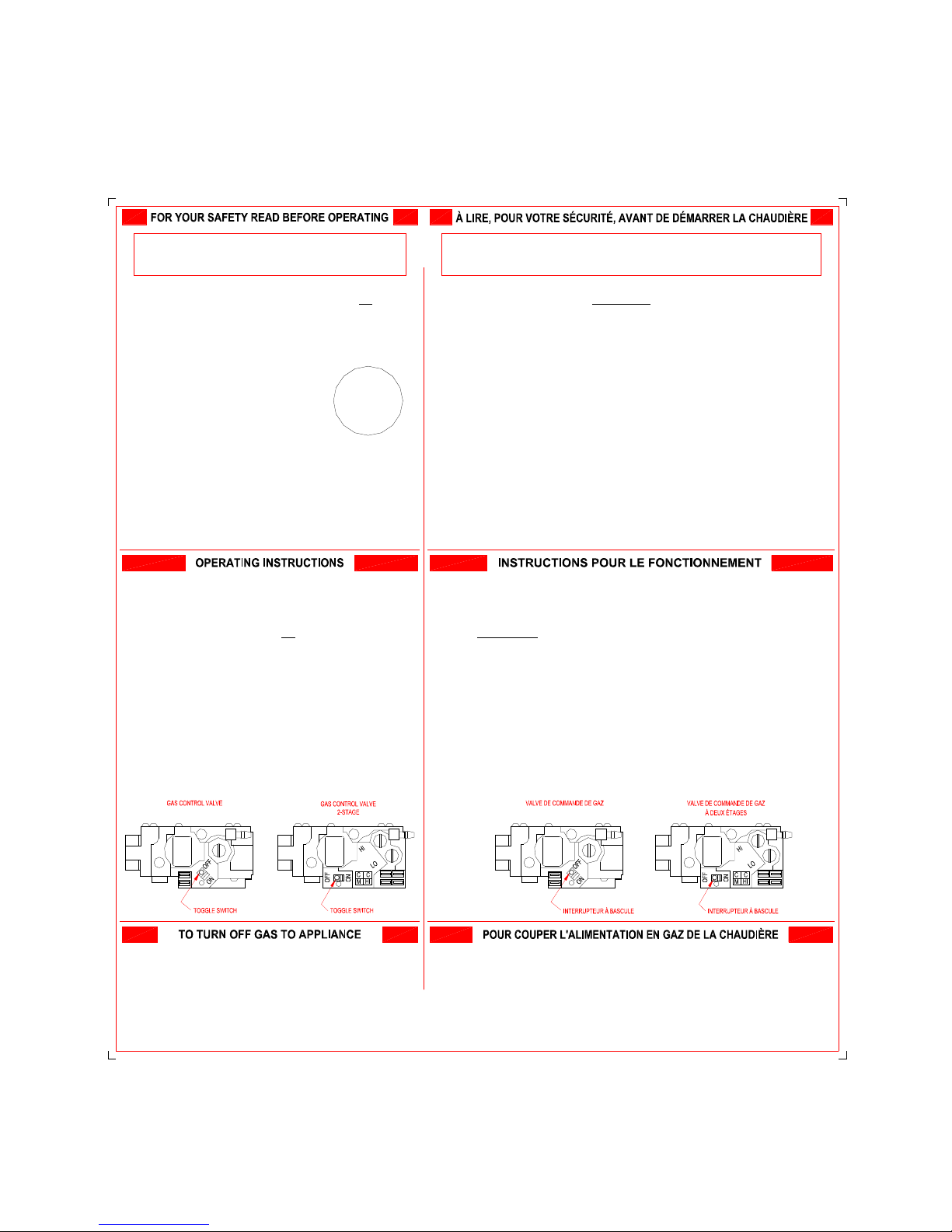
This and the previous page contain reproductions of the various warning and instruction labels placed on the Thermo
Pride Condensing Gas Furnaces. Please read and comply with the contents of these labels.
WARNING:
fire or explosion may result causing property damage,
personal injury or loss of life.
A. This appliance does not have a pilot. It is equipped with a hot
surface igniter that automatically lights the burner. Do not try to
light the burner by hand.
B. BEFORE OPERATING smell all around the appliance area for gas.
Be sure to smell next to the base of unit because some gas is
heavier than air and will settle on the floor or ground.
WHAT TO DO IF YOU SMELL GAS
?
Do not try to light any appliance.
?
Do not touch any electric switch; do not use
any phone in your building.
?
Immediately call your gas supplier from a
neighbor's phone. Follow the gas supplier's
instructions.
?
If you cannot reach your gas supplier, call the fire department.
C. Use only your hand to move the gas control switch. Never use tools.
If the switch will not move by hand, don't try to repair it, call a
qualified service technician. Force or attempted repair may result in
a fire or explosion.
D. Do not use this appliance if any part has been underwater.
Immediately call a qualified service technician to inspect the
appliance and to replace any part of the control system and any gas
control which has been underwater.
1. STOP! Read the safety information above on this label.
2. Set the thermostat to the lowest setting.
3. Turn off all electric power to the appliance.
4. This appliance is equipped with a hot surface igniter that
automatically lights the burner. Do not try to light the burner by
hand.
5. Move the gas control switch to the "OFF" position.
6. Wait five (5) minutes to clear out any gas. Then smell for gas,
including near the floor or ground. If you smell gas, STOP! Follow
"B" in the safety information above on this label. If you don't smell
gas, go to the next step.
7. Move the gas control switch to the "ON" position.
8. Turn on all electric power to the appliance.
9. Set thermostat to desired setting, and, if equipped, set the operating
mode to "HEAT".
10.If appliance will not operate, follow the instructions "To Turn Off
Gas To Appliance" and call your service technician or gas supplier.
1. Set thermostat to lowest setting, and, if equipped, set the operating
mode to "COOL" or "OFF".
2. If service is to be performed, turn off all electric power to the
appliance.
3. To turn off gas control valve, remove the burner compartment cover.
4. Move the gas control switch to the "OFF" position.
5. Replace the burner compartment cover.
If you do not follow these instructions exactly, a
ATTENTION ! Si vous ne respectez pas exactement les instructions ci-dessous, un
incendie ou une explosion pourraient endommager la propriété, blesser ou tuer des
personnes.
A. Cet appareil n'a pas de veilleuse. Il comporte une surface d'allumage chaude qui
allume automatiquement le brûleur. N'essayez pas d'allumer le brûleur manuellement.
B. AVANT DE DÉMARRER la chaudière, humez l'air autour de l'appareil pour détecter une
éventuelle odeur de gaz. Humez aussi l'air près de la base de la chaudière puisque le
gaz étant plus lourd que l'air, il pourrait s'accumuler près du sol ou du plancher.
QUOI FAIRE SI VOUS SENTEZ UNE ODEUR DE GAZ
?
N'allumez aucun appareil.
?
Ne touchez aucun interrupteur électrique; n'utilisez aucun téléphone dans
l'immeuble.
?
Appelez immédiatement votre fournisseur de gaz à partir du téléphone d'un voisin.
Suivez ses instructions.
?
Si vous ne pouvez pas joindre votre fournisseur de gaz, appelez les pompiers.
C. Manipulez l'interrupteur de commande de gaz seulement à la main. N'utilisez jamais
des outils pour cela. Si vous ne pouvez pas manipuler cet interrupteur manuellement,
n'essayez pas de le réparer, appelez un technicien de service qualifié. Forcer
l'interrupteur ou tenter de le réparer, pourraient provoquer un incendie ou une
explosion.
D. N'utilisez pas la chaudière si l'une de ses pièces a été sous de l'eau. Appelez
immédiatement un technicien de service qualifié pour qu'il inspecte la chaudière et
remplace toute pièce du système de commande et tout interrupteur de commande de
gaz qui ont été sous de l'eau.
1. STOP ! Lisez l'information sur la sécurité au haut de cette étiquette.
2. Réglez le thermostat à sa position la plus basse.
3. Coupez toute l'alimentation électrique la chaudière.
4. Cette chaudière est équipée d'une surface d'allumage chaude qui allume automatiquement le
brûleur. N'essayez pas d'allumer le brûleur manuellement.
5. Placez l'interrupteur de commande de gaz à la position «OFF».
6. Attendez cinq (5) minutes pour que tout le gaz soit évacué. Humez l'air pour détecter une
éventuelle odeur de gaz, sans oublier de l'humer aussi près du sol ou du plancher. Si vous
sentez une odeur de gaz, STOP ! Suivez le point «B» de l'information sur la sécurité au haut de
cette étiquette. Si vous ne sentez aucune odeur de gaz, passez à l'étape suivante.Move the gas
control switch to the "ON" position.
7. Placez l'interrupteur de commande de gaz à la position «ON».
8. Appliquez toute l'alimentation électrique à la chaudière.
9. Réglez le thermostat à la position désirée et, le cas échéant, mettez le mode de
fonctionnement à la position «HEAT».
10.Si la chaudière ne fonctionne pas, suivez les instructions de « POUR COUPER
L'ALIMENTATION EN GAZ DE LA CHAUDIÈRE» et appelez votre technicien de service ou votre
fournisseur de gaz.
1. Réglez le thermostat à sa position la plus basse et, le cas échéant, réglez le mode de
fonctionnement à la position «COOL» ou «OFF».
2. S'il faut accomplir une certaine tâche, coupez toute alimentation en électricité de la
chaudière.
3. Pour fermer la valve de commande de gaz, enlevez le couvercle du compartiment du brûleur.
4. Mettez l'interrupteur de commande de gaz à la position «OFF».
5. Replacez le couvercle du compartiment du brûleur.
390568
5
Page 6

All installations and services must be performed by qualified service personnel.
This page contains various warnings and cautions found throughout this Furnace Manual. Please read and comply
with the statements below.
The following safety information should be read, understood, and followed by the installer.
1. Use only with type of gas approved for this furnace. Refer to furnace rating plate.
2. Connect this furnace to an approved vent system only. Combustion products must be discharged
outdoors. Connect this furnace to an approved vent system only, as specified in section III parts D though
H of these instructions.
: This furnace is not to be used for temporary heating of buildings or structures under construction.
: These high efficiency condensing furnaces are not certified for and shall not be vented into a
standard or any type of chimney.
: These furnaces may not be common vented with any other appliance.
: The vent and air intake elbows must be kept away from bushes, shrubs or any vegetation that may
restrict the flow of flue products. It must also be kept clear of any leaves, weeds or other combustible materials.
Keep the vent hood clear of snow. Avoid locating the terminals in areas where standing water or condensate
drippage may be a problem.
: Outside combustion air must not come from an area that is directly adjacent to a pool, hot tub or
spa. Measures should be taken to prevent the entry of corrosive chemicals or vapors to the combustion and
ventilation air supply. Such chemicals include but are not limited to chlorinated and/or fluorinated hydrocarbons
such as found in refrigerants, aerosol propellants, dry cleaning fluids, degreasers , bleaches, air fresheners or
solvents. Vapors from such products can form acid compounds when burned in a gas flame. Should acid
compounds form in your furnace; it may reduce the life of the furnace.
: Because of the potential of odorant fade, a gas leak may not be detected by smell. If this furnace
is installed below grade, contact your gas supplier for a gas detector.
: Turn off power to furnace before it is placed into service. The gas piping system must have been
leak tested by a qualified heating contractor.
: It may be necessary to purge the air out of the gas line for initial start-up of the furnace after
installation. This should be done by a qualified heating contractor. If excessive gas escapes when purging the gas
supply at the union, allow the area to ventilate for at least 15 minutes before attempting to start the furnace. LP
gas is especially dangerous because the specific gravity of LP gas allows it to accumulate at floor level at a
dangerous concentration. For remainder of operating instructions, reference Users Information Manual.
: Heat exchanger oil will burn off on initial firing creating an unpleasant odor. To prevent this
odor from occurring more than once, it is suggested that:
1. A window(s) be opened.
2. The thermostat set at highest setting.
3. The furnace remain running at conditions 1&2 for 30 minutes or until odor has dissipated
: These furnace models are a sealed combustion design, which does not require an air shutter
adjustment (air shutters are not used) for proper flame characteristics. Burner door must always be closed before
operating furnace.
6
Page 7
All installations and services must be performed by qualified service personnel.
13
Category
irflow Cap
: Personal injury or property damage could result from repair or service of this furnace by anyone
other than a qualified heating contractor. Only the homeowner/user routine maintenance described in the Users
Information Manual may be performed by the user.
FURNACE MODEL NO. NOMENCLATURE
Model Number Digit 1 2 3 4 5 6 7 8 9 10 11 12
Input Input
Profile
Gas Furnace Model Nomenclature Example Model Numbers C L H S 1 - 0 5 0 P 3
C = Condensing C
L = Low-profile L
H = Highboy H
Stage: S = Single, X = 2-Stage S
Version (Rev) 1
Input Capacity in MBTUH (1000) - 0 5 0
Motor Type: P = PSC, T = CTM, E = ECM P
Cooling Airflow Capacity in MBTUH (1000) 3 6
Gas Type: N = Natural, P = Liquid Propane
7
C L H X 1 - 1 2 5 E 6
Staging
Version
Configuration
Input
Motor Type
Clg Airflow Cap Clg A
Gas Type
6 N
0 N
N
Page 8
All installations and services must be performed by qualified service personnel.
II. FURNACE SPECIFICATIONS
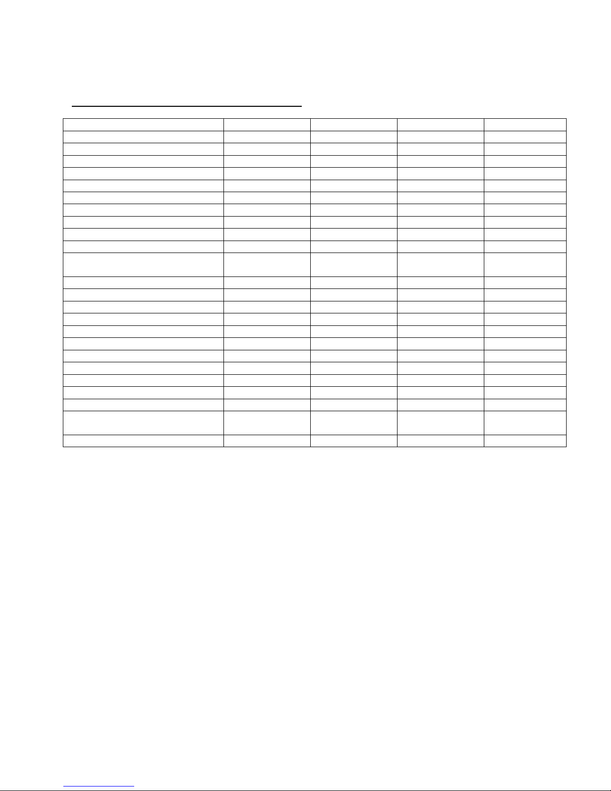
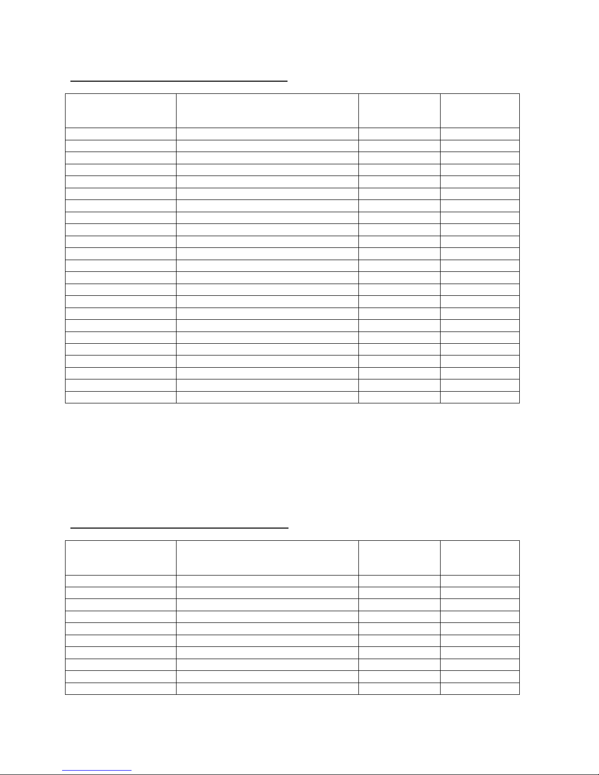
A. CLHS1 SERIES (Single Stage, PSC Blower Motor)
MODEL NO. CLHS1-050P CLHS1-075P CLHS1-100P CLHS1-125P
BTU/Hr INPUT
BTU/Hr OUTPUT
HT. OF CASING
WIDTH OF CASING
DEPTH OF CASING
WARM AIR OUTLET
RETURN AIR INLET
DIA. OF FLUE
DIA. OF COMBUSTION
AIR INTAKE
CFM @ 0.2” & 0.5” w.c. STATIC
@HI SPEED (BLACK)
@MH SPEED (YELLOW)
@ML SPEED (BLUE)
@LO SPEED (RED, HEATING)
TEMPERATURE RISE
BLOWER MOTOR HP
NO. OF SPEEDS
RUN CAPACITOR
LARGEST RECOMMENDED
AIR CONDITIONER
SIZE OF FILTERS
NOTES:
1. BTU output based on annual fuel utilization efficiency rated by manufacturer.
2. On all outlet and inlet dimensions, the first dimension is width.
3. Electrical characteristics at 120 volts, 60 Hz., 1 phase (less than 15 amps. for all models).
4. All specifications are subject to change without notice.
50,000 75,000 100,000 125,000
48,000 73,000 96,000 120,000
34-1/2” 34-1/2” 34-1/2” 34-1/2”
17-1/2” 21” 21” 24-1/2”
28-1/2” 28-1/2” 28-1/2” 28-1/2”
16-1/2 x 20 20 x 20 20 x 20 23-1/2 x 20
25 x 16 25 x 16 25 x 16 25 x 16
2” 2” 3” 3”
2” 2” 3” 3”
0.2” - 0.5” 0.2” - 0.5” 0.2” - 0.5” 0.2” - 0.5”
1507 - 1150 1647 - 1318 1844 – 1442 2267 - 1920
1145 - 943 1428 - 1193 1654 – 1325 2011 - 1755
901 - 733 954 - 890 1294 – 1145 1767 - 1542
633 - 452 697 - 656 904 – 852 1527 - 1337
60 60 60 60
1/2 1/2 3/4 3/4
4 4 4 4
10 mfd 15 mfd 15 mfd 15 mfd
3 Ton 3.5 Ton 4 Ton 5 Ton
24-3/4” x 15-3/4” 24-3/4” x 15-3/4” 24-3/4” x 15-3/4” 24-3/4” x 19-3/4”
8
Page 9
All installations and services must be performed by qualified service personnel.
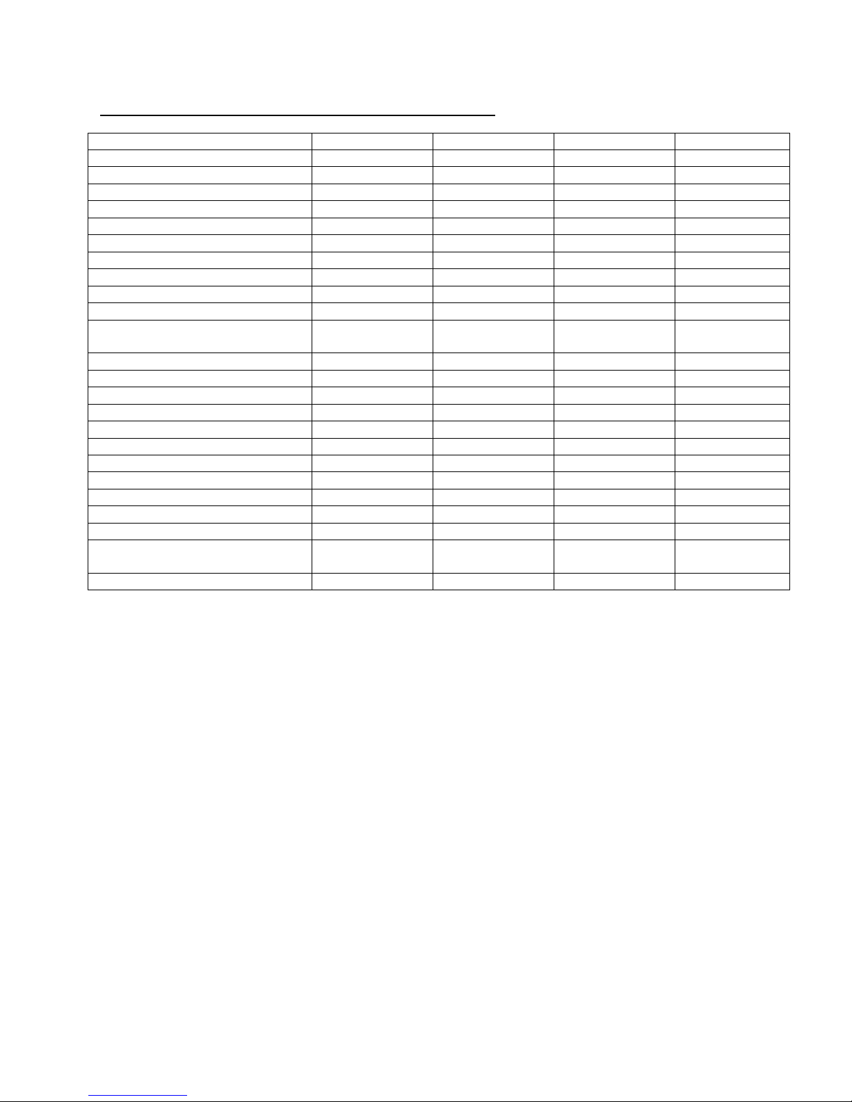
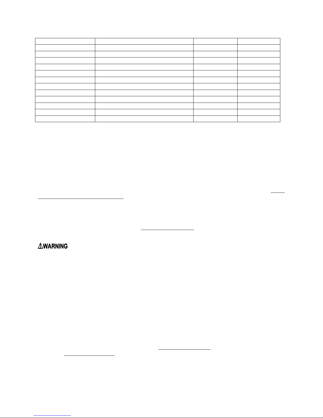
B. CLHS1 SERIES (Single Stage, Constant Torque Blower Motor)
MODEL NO. CLHS1-050T CLHS1-075T CLHS1-100T CLHS1-125T
BTU/Hr INPUT
BTU/Hr OUTPUT
HT. OF CASING
WIDTH OF CASING
DEPTH OF CASING
WARM AIR OUTLET
RETURN AIR INLET
DIA. OF FLUE
DIA. OF COMBUSTION
AIR INTAKE
CFM @ 0.2” & 0.5” w.c. STATIC
@HI SPEED (BLACK)
@MH SPEED (YELLOW)
@MED SPEED (BLUE)
@ML SPEED (PURPLE)
@LO SPEED (RED, HEATING)
TEMPERATURE RISE
BLOWER MOTOR HP
NO. OF SPEEDS
LARGEST RECOMMENDED
AIR CONDITIONER
SIZE OF FILTERS
NOTES:
1. BTU output based on annual fuel utilization efficiency rated by manufacturer.
2. On all outlet and inlet dimensions, the first dimension is width.
3. Electrical characteristics at 120 volts, 60 Hz., 1 phase (less than 15 amps. for all models).
4. All specifications are subject to change without notice.
50,000 75,000 100,000 125,000
48,000 73,000 96,000 120,000
34-1/2” 34-1/2” 34-1/2” 34-1/2”
17-1/2” 21” 21” 24-1/2”
28-1/2” 28-1/2” 28-1/2” 28-1/2”
16-1/2 x 20 20 x 20 20 x 20 23-1/2 x 20
25 x 16 25 x 16 25 x 16 25 x 16
2” 2” 3” 3”
2” 2” 3” 3”
0.2” - 0.5” 0.2” - 0.5” 0.2” - 0.5” 0.2” - 0.5”
1360 - 1193 1531 – 1368 1762 – 1547 2047 – 1882
1167 - 1000 1379 – 1210 1558 – 1391 1813 – 1617
987 - 797 1189 – 982 1416 – 1229 1710 – 1513
827 - 610 1133 – 933 1357 – 1186 1553 – 1330
672 - 420 1025 – 800 1178 – 976 1444 – 1180
60 60 60 60
1/2 1/2 3/4 3/4
5 5 5 5
3 Ton 3.5 Ton 4 Ton 5 Ton
24-3/4” x 15-3/4” 24-3/4” x 15-3/4” 24-3/4” x 15-3/4” 24-3/4” x 19-3/4”
9
Page 10
All installations and services must be performed by qualified service personnel.
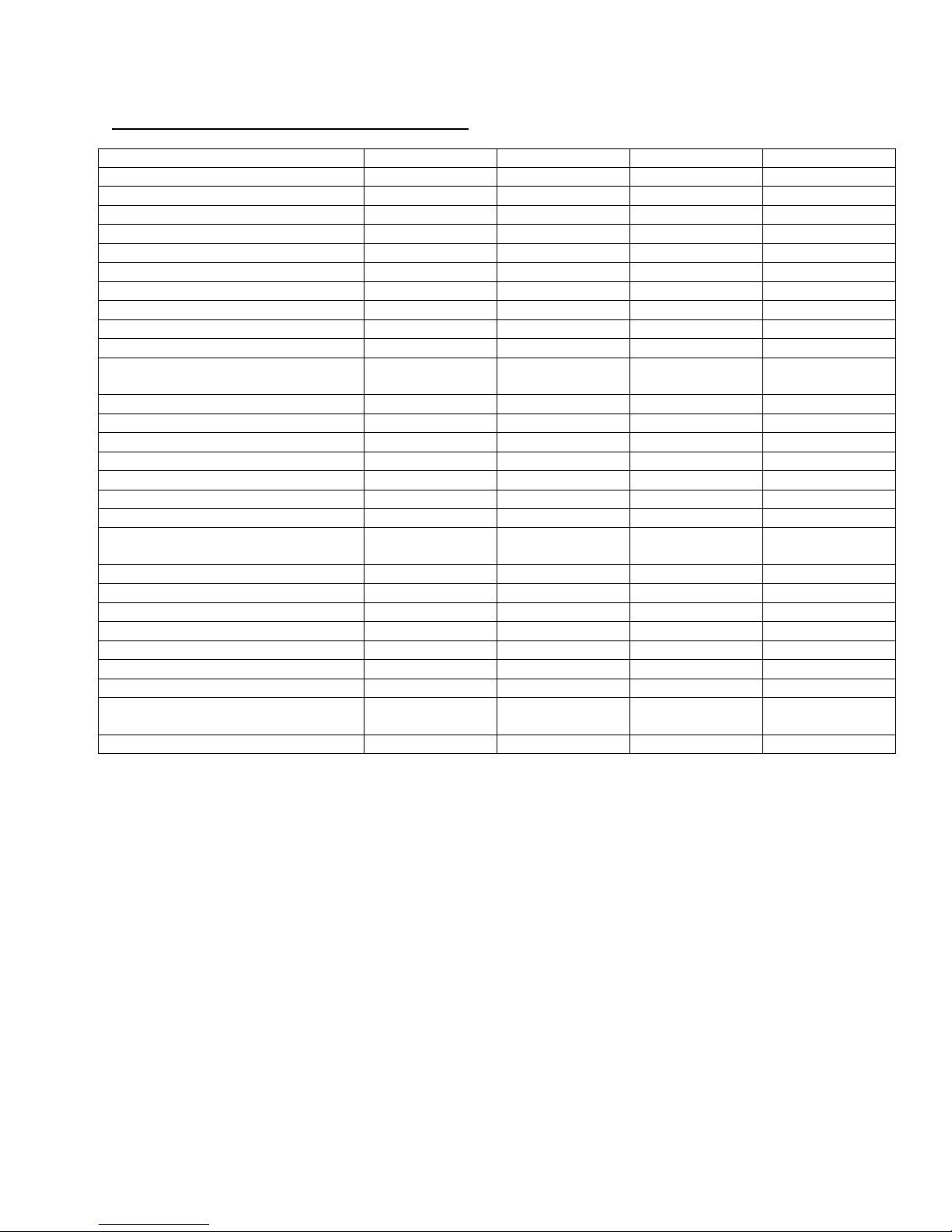
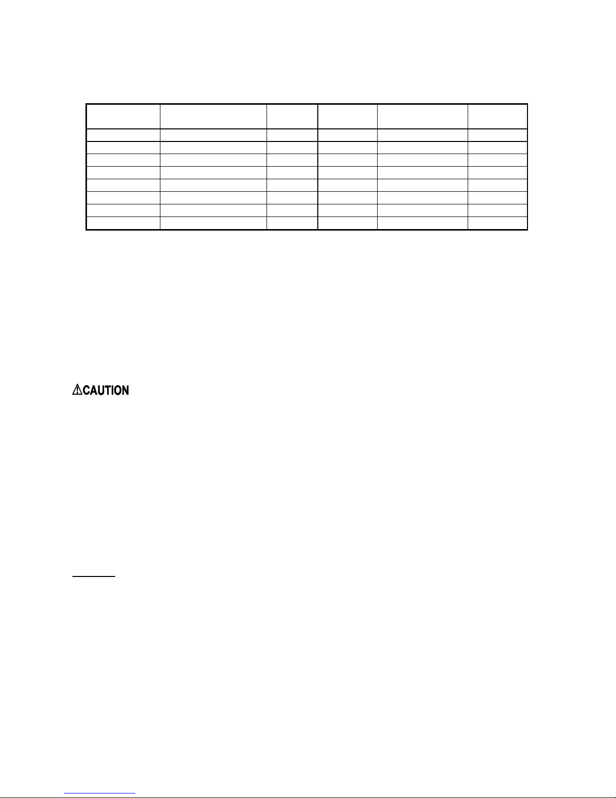
C. CLHX1 SERIES (Two Stage, ECM Blower Motor)
MODEL NO. (High fire/Low fire) CLHX1-050E CLHX1-075E CLHX1-100E CLHX1-125E
BTU/Hr INPUT
BTU/Hr OUTPUT
HEIGHT OF CASING
WIDTH OF CASING
DEPTH OF CASING
WARM AIR OUTLET
RETURN AIR INLET
DIA. OF FLUE
DIA. OF COMBUSTION
AIR INTAKE
CFM
@ COOLING TAP A
@ COOLING TAP B
@ COOLING TAP C
@ COOLING TAP D
CFM
(High fire/Low fire)
@ HEATING TAP A
@ HEATING TAP B
@ HEATING TAP C
@ HEATING TAP D
TEMPERATURE RISE
BLOWER MOTOR HP
LARGEST RECOMMENDED
AIR CONDITIONER
SIZE OF FILTERS
NOTES:
1. BTU output based on annual fuel utilization efficiency rated by manufacturer.
2. On all outlet and inlet dimensions, the first dimension is width.
3. Electrical characteristics at 120 volts, 60 Hz., 1 phase (less than 15 amps. for all models).
4. All specifications are subject to change without notice.
50,000 / 35,000 75,000 / 53,000 100,000 / 70,00 125,000 / 75,000
48,000 / 34,000 73,000 / 51,000 97,000 / 68,000 120,000 / 71,000
34-1/2” 34-1/2” 34-1/2” 34-1/2”
17-1/2” 21” 21” 24-1/2”
28-1/2” 28-1/2” 28-1/2” 28-1/2”
16-1/2 x 20 20 x 20 20 x 20 23-1/2 x 20
25 x 16 25 x 16 25 x 16 25 x 16
2” 2” 3” 3”
2” 2” 3” 3”
711 850 1031 1246
870 1055 1236 1420
1061 1257 1428 1617
1241 1386 1621 2000
432 / 617 648 / 926 841 / 1201 869 / 1448
489 / 698 722 / 1031 921 / 1315 963 / 1605
534 / 762 791 / 1130 1039 / 1484 1080 / 1800
589 / 841 909 / 1298 1207 / 1724 1210 / 2017
60 60 60 60
1/2 1/2 3/4 3/4
3 Ton 3.5 Ton 4 Ton 5 Ton
24-3/4” x 15-3/4” 24-3/4” x 15-3/4” 24-3/4” x 15-3/4” 24-3/4” x 19-3/4”
10
Page 11
All installations and services must be performed by qualified service personnel.
D. INSTALLATION PARTS PACKAGES - CLHS1
PARTS PACKAGE
#S00S4541/4542/
4543/4544
S00S4541 LP Gas Conversion Kit (050) AOPS7746 1
S00S4542 LP Gas Conversion Kit (075) AOPS7747 1
S00S4543 LP Gas Conversion Kit (100) AOPS7748 1
S00S4544 LP Gas Conversion Kit (125) AOPS7749 1
Installation notice MG-966 1
E. INSTALLATION PARTS PACKAGES - CLHX1
PARTS PACKAGE
#S00S4545/4546/
4547/4548
#10-32 x ½ green ground screw 300109 1
#10-32 hex nut 300110 1
Wire nut 300132 2
#8 x ½ TEK screws for mounting J-box 300208 6
3/16” dia. star washer 300270 1
#8 x ¾ TEK screws for mounting trap 300283 2
Spring clamp, 11/16” 300299 2
Adapter, ½" CPVC X PVC 320833 1
Trap Assembly 320928 1
Grommet for 2” PVC flue pipe 350007 1
Grommet for ½” gas pipe 350009 1
J-box wire bushing 350016 1
2 x 4 electrical J-box cover 350020 1
2 x 4 electrical J-box 350024 1
Grommet for 11/16” drain tubing 350210 2
Thermostat wire busing 350750 1
5/16” tubing, 13” long 410061 1
Flange for 2” PVC air intake 614524 1
#10-32 x ½ green ground screw 300109 1
#10-32 hex nut 300110 1
Wire nut 300132 2
#8 x ½ TEK screws for mounting J-box 300208 6
3/16” dia. star washer 300270 1
#8 x ¾ TEK screws for mounting trap 300283 2
Spring clamp, 11/16” 300299 2
Adapter, ½" CPVC X PVC 320833 1
Trap Assembly 320928 1
Grommet for 2” PVC flue pipe 350007 1
DESCRIPTION PART # QUANTITY
DESCRIPTION PART # QUANTITY
11
Page 12
All installations and services must be performed by qualified service personnel.
S00S4545 LP Gas Conversion Kit (050) AOPS7751 1
S00S4546 LP Gas Conversion Kit (075) AOPS7752 1
S00S4547 LP Gas Conversion Kit (100) AOPS7753 1
S00S4548 LP Gas Conversion Kit (125) AOPS7754 1
Installation notice MG-966 1
III. GENERAL INSTALLATION
Install this furnace only in a location and position as specified in Section III of these instructions.
This furnace is equipped with orifices size for operation with natural gas. For conversion to Propane Gas see
instruction in Gas Conversion Section of this manual.
These Category Type IV furnaces are shipped completely assembled and wired (internally). See the Dealer
Receiving and Freight Claim Procedure Section of the price guide for parts shortage or damage. The furnace and
duct system must be adjusted to obtain a temperature rise of 45°F to 75°F through the furnace after installation. The
recommended minimum return air temperature is 55°F. Always install furnace to operate within the furnace’s
intended temperature rise range with a duct system which has an external static pressure within the allowable range,
as specified in Section III of these instructions. See furnace rating plate. The installation must conform with local
codes, or in the absence of local codes, with the National Fuel Gas Codes (ANSI Z223.1 or latest edition), and these
instructions.
: This furnace is not to be used for temporary heating of buildings or structures under construction.
Many of the chemicals used during construction, when burned, form acid bearing condensate that can substantially
reduce the life of the heat exchanger.
It is recommended that a commercially available CO alarm be installed in conjunction with any fossil fuel burning
appliance. The CO alarm shall be installed according to the alarm manufacturer’s installation instructions and be
listed in accordance with the latest edition of the UL Standard for Single and Multiple Station Carbon Monoxide
Alarms, UL 2034, or the CSA International Standard, Residential Carbon Monoxide Alarming Devises, CSA 6.19.
A. CODES AND CLEARANCES
The following items must be considered when choosing the size and location of the furnace.
Grommet for ½” gas pipe 350009 1
J-box wire bushing 350016 1
2 x 4 electrical J-box cover 350020 1
2 x 4 electrical J-box 350024 1
Grommet for 11/16” drain tubing 350210 2
Thermostat wire busing 350750 1
5/16” tubing, 13” long 410061 1
Flange for 2” PVC air intake 614524 1
1. All local codes and/or regulations take precedence over the instructions in this manual and should be followed
accordingly. In the absence of local codes, installation must conform with these instructions, regulations of the
National Fire Protection Association, provisions of National Electrical Code (ANSI/NFPA70 or latest edition),
and the National Fuel Gas Code (ANSI Z223.1 or latest edition).
2.
The BTU output capacity of the furnace proposed for installation should be based on a heat loss calculation
made according to the manuals provided by the Air Conditioning Contractors of America (ACCA) or ASHRAE.
12
Page 13
All installations and services must be performed by qualified service personnel.
3. MINIMUM CLEARANCES TO COMBUSTIBLE MATERIALS
MODEL NO.
CLHS1-050
CLHS1-075
CLHS1-100
CLHS1-125
CLHX1-050
CLHX1-075
CLHX1-100
CLHX1-125
FROM SIDES OF
FURNACE & REAR
0 IN. 6 IN. 0 IN. 0 IN. 1 IN.
0 IN. 6 IN. 0 IN. 0 IN. 1 IN.
0 IN. 6 IN. 0 IN. 0 IN. 1 IN.
0 IN. 6 IN. 0 IN. 0 IN. 1 IN.
0 IN. 6 IN. 0 IN. 0 IN. 1 IN.
0 IN. 6 IN. 0 IN. 0 IN. 1 IN.
0 IN. 6 IN. 0 IN. 0 IN. 1 IN.
0 IN. 6 IN. 0 IN. 0 IN. 1 IN.
FRONT
TABLE 1
TOP OF
PLENUM
FROM THE
FLUE OR VENT
SIDE OF
PLENUM
The CLHS1 & CLHX1 furnaces may be installed on combustible flooring. The furnace shall not be installed directly
on carpeting or other combustible material other than wood flooring. These furnaces may be installed in an alcove or
in a closet if the minimum clearances to combustible construction (listed previously) are met. The minimum
clearances are listed for fire protection. Clearance for servicing the front of the furnaces and to all points on the
furnace requiring access must be 24”.
Equipment must be installed in accordance with regulations of the National Board of Fire Underwriters.
Authorities having jurisdiction should be consulted before installations are made.
B. FURNACE LOCATION
: These high efficiency condensing furnaces are not certified for and shall not be vented into a
standard or any type of chimney.
The following shall be considered for locating the furnace:
1. For best performance locate the furnace so that it is centralized with respect to the duct system and as near as
possible to a floor drain since condensate drainage must be provided.
2. Place the unit so that proper venting can be achieved, with a minimum number of elbows, in accord with the
instructions in this manual.
3. The furnace must be located on a level, dry surface. The furnace must be installed so that the electrical
components are protected from water. If the area becomes wet or damp at times, the furnace should be raised
above the floor using a concrete base, bricks, patio blocks, etc.
NOTICE: Ensure furnace is level after installation to ensure proper drainage and operation.
4. This furnace must be connected to a drain in accordance with these instructions. If it is not practical to connect
the unit to a drain, a condensate pump must be used and can be ordered as an accessory, part number 350224. If
an acid neutralizer kit is required by local code or the customer, it is available under part number 320095.
5. A Furnace installed in a residential garage must be installed so the burner and ignition source are located higher
than 18 inches above the floor. Also, the furnace must be located or protected to avoid physical damage by
vehicles.
6. A gas fired furnace for installation in a residential garage must be installed as specified in Section III of these
instructions.
13
Page 14

All installations and services must be performed by qualified service personnel.
C. REPLACING EXISTING FURNACE FROM A COMMON VENT
: These furnaces may NOT be common vented with any other appliance.
D. GENERAL REQUIREMENTS FOR VENTING
The furnace venting system must be installed by a qualified service person in accordance with local installation
codes and these instructions. In the absence of applicable local codes, conform to the National Fuel Gas Code, NFPA
54 /ANSI Z223.1-2002, or latest edition thereof.
Provide adequate combustion and ventilation air to the furnace space as specified in Section III parts D through H.
Installation shall, at least, conform to the following requirements.
1. The exhaust vent / combustion air intake terminations specified by Thermo Products, in this manual, shall
be used.
2. All plastic pipe and pipefittings sourced to complete the exhaust vent and air intake systems shall be
constructed of rigid PVC (polyvinyl chloride) thermoplastic. All components shall have a wall thickness
equivalent to Schedule 40 series materials.
In addition, all sourced PVC components shall be listed by a nationally recognized testing agency (e.g.
NSF, UL, etc.) as conforming to one (1) or more of the following design standards.
PVC Pipe Designation Design Standard
Cellular Core ASTM-F891
DWV (Drain-Waste-Vent) ASTM-D2665
Schedule 40 ASTM-D1785
3. The exhaust vent pipe and combustion air pipe shall be at least as large as the exhaust vent / air intake pipe
specified by Thermo Products. Size reduction is never permissible. The required exhaust vent / air intake
pipe sizes are:
•
2-inch PVC thermoplastic pipe, for models CLHS1–050/075 & CLHX1-050/075
•
3-inch PVC thermoplastic pipe, for models CLHS1–100/125 & CLHX1–100/125
4. All horizontal runs of exhaust vent pipe shall slope upward at least ¼ inch per foot from the outlet of the
furnace to the vent termination, beyond the outside wall. This slope will permit proper drainage of the
condensate.
Horizontal runs of air intake pipe shall slope downward at least ¼ inch per foot from the outlet of the last
elbow or last horizontal run, before exiting the wall, to the intake termination beyond the outside wall. This
slope will permit proper drainage of any precipitation that enters the intake pipe.
5. The exhaust vent pipe shall be supported at every joint (no more than 4-feet between supports) to prevent
pipe blockage due to condensate trapped at a local low point, or sag, in the vent system.
14
Page 15
All installations and services must be performed by qualified service personnel.
6. The maximum permissible length of piping (consisting of a combination of straight pipe and a
corresponding number of elbows) permitted is:
• 75 equivalent feet, for the exhaust vent system, and
• 75 equivalent feet, for the combustion air intake system
7. The maximum quantity of Schedule 40 series, type DWV thermoplastic pipe elbows allowed in each system
is listed in Table 2. When counting pipe elbows, this excludes all elbows, or equivalent pipefittings, used
inside the furnace jacket in addition to those used to construct the termination. Furthermore, a credit of 5feet of straight pipe may be taken for each elbow, up to maximum of three (3) elbows, which is dropped
from the maximum permissible number for each system.
Thermoplastic Pipe
Vent Size (Nominal)
Furnace Model
Exhaust or
Pipe Len.
2 in. Diameter IPS
Intake
(ft.)
CLHS1 / CLHX1-50 35 8 8 - - CLHS1 / CLHX1-75
CLHS1 / CLHX1-100
Not Permitted
CLHS1 / CLHX1-125
Superscripts:
1
Two (2) 45° elbows can be substituted for one (1) 90° elbow.
Care should be taken to design the shortest possible intake and exhaust systems. Each system should contain
as few elbows as possible to insure the satisfactory operation of the furnace. However, system length should
never be less than 5 ft of pipe with two (2) 90 deg. elbows. This is separate from the elbows used at the
termination and those inside the furnace cabinet. For best overall operation of the combustion system, we
recommend the actual equivalent lengths for both the constructed intake and the exhaust systems have
approximately the same value.
8. Use a saw designed to cut thermoplastic pipe. All cuts should be made at right angles to the pipe wall.
Smooth jagged edges and remove all burrs and strings. All pipe joints must utilize standard PVC
Schedule 40 series, DWV type elbows, couplings, and fittings. Clean all pipe surfaces at connections
using a fine abrasive material or approved PVC cleaner (primer). Secure all pipe joints using suitable
permanent PVC pipe solvent cement. Joints are NOT to be made by simply gluing raw edges of butted
together vent pipe.
Piping joints inside the furnace vestibule should be sealed with silicone caulk, rather than pipe cement, to
allow for disassembly and removal of piping, if necessary, during maintenance.
Seal the vent installation by caulking the gap around the two (2) holes where the thermoplastic pipes pass
through the wall.
NOTICE: Use silicone caulk to seal the Combustion Air pipe as it passes through the 2” Intake Air
Flange.
9. Vent connections shall be checked for leakage with the furnace running. Use a mild soap and water solution
to check for leaks.
Maximum
Qty. of
Exhaust
Elbows
1
TABLE 2
Maximum
Qty. of
Intake
Elbows 1
Exhaust or
Intake
Pipe Len.
(ft.)
35
3 in. Diameter IPS
Maximum
Qty. of
Exhaust
Elbows 1
8
Maximum
Qty. of
Intake
Elbows 1
8
15
Page 16
All installations and services must be performed by qualified service personnel.
10. Vent pipe passing through an unheated space shall be insulated with 1-inch thick, foil-faced fiberglass
insulation, or equivalent, to prevent freezing of condensate within the pipe.
11. No clearance is required from the outer surface of the thermoplastic piping to combustible materials for fire
hazard prevention.
12. Thermo Products does not require screens be installed in the exhaust vent and air intake piping. However,
optional stainless steel screens are available from Thermo Products, under part no. 320226 for 3” vent and
320219 for 2” vent.
NOTICE: The furnace may be vented either through the sidewall or the roof. For sidewall instructions,
continue to the following section. For roof venting, refer to Section III G, of this manual
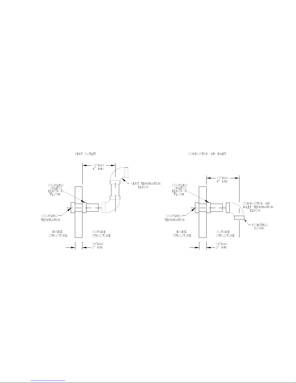
E. SIDEWALL VENTING
1. Vent and combustion air pipes may pass through a maximum wall thickness of 18 inches. The minimum
wall thickness is 2 inches. Referring to Figure 1, the maximum distance from the outer wall to the center of
the elbow is 12 inches.
NOTICE: If exterior sidewall building materials are subject to degradation from contact with flue gases or
moisture, a minimum 24-inch diameter shield shall be fabricated from stainless steel or UV-resistant plastic
sheet. The protective shield shall be installed around the vent pipe on the outside wall.
2. The exhaust vent termination elbow shall be installed in accordance with these instructions and any
applicable local codes. Refer to Figures 1 and 2 for typical examples of proper terminations.
a. The exhaust vent termination must be installed in the same atmospheric pressure zone (i.e. on the same
wall) as the air intake termination.
b. The bottom edge of the vent termination elbow must be installed at least 12-inches above the outlet of
intake termination elbow.
Figure 1: Proper Direct Vent Terminations
16
Page 17
All installations and services must be performed by qualified service personnel.
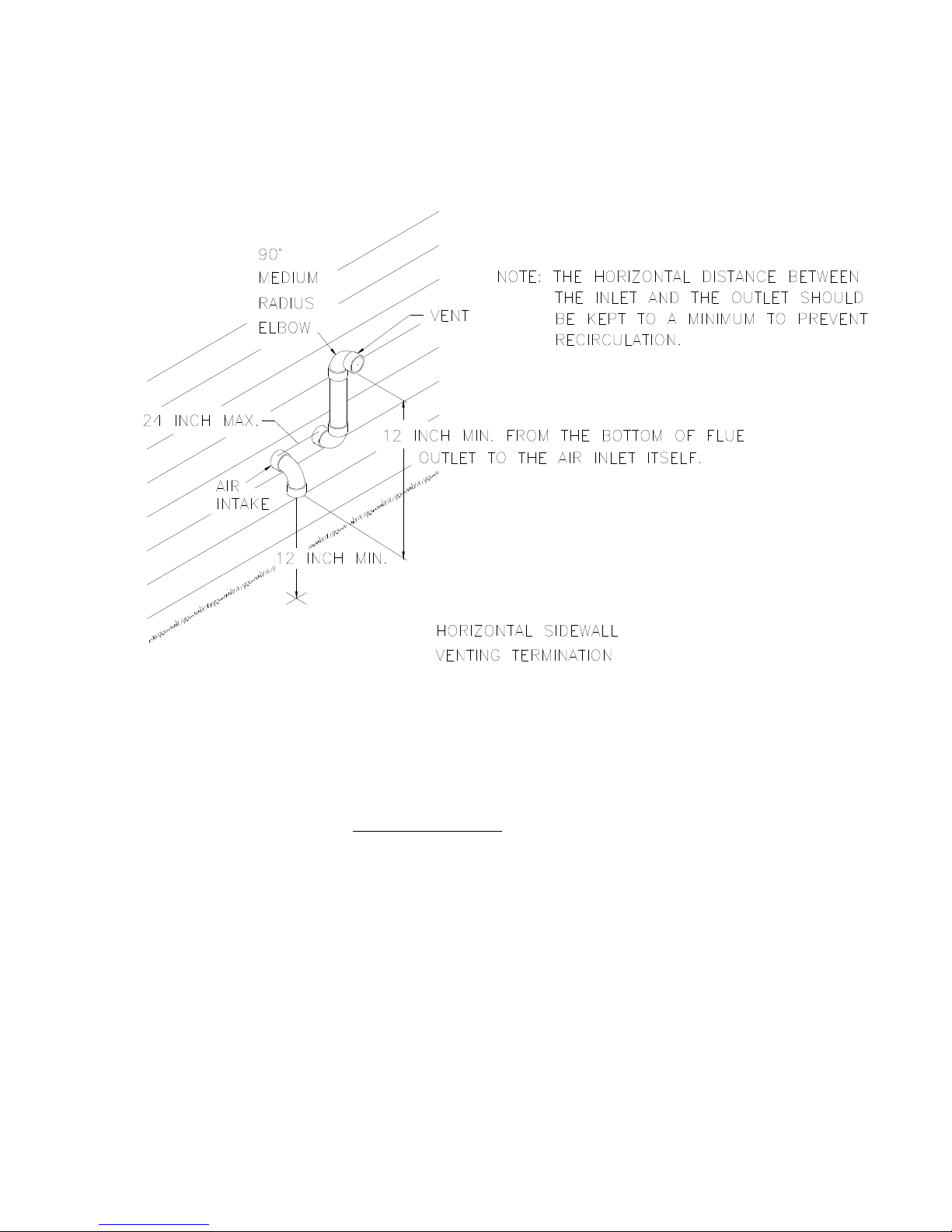
c. The horizontal distance between the inlet and exhaust terminations should be minimized, when
possible, and should never exceed 24-inches.
d. The vent and intake systems should utilize the same numbers of elbows and approximately the same
length of straight pipe to reach the outside termination.
Figure 2: Typical Relative Locations of Direct Vent Terminations When Sidewall Venting
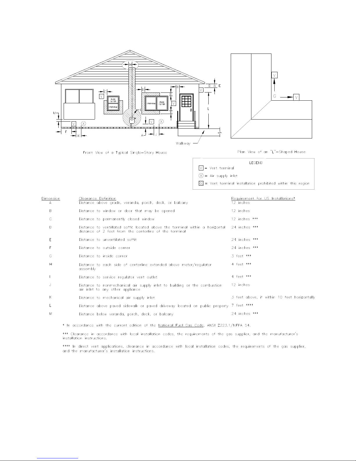
3. Exhaust Vent Terminal Location Clearance Requirements
a. The vent terminal shall be located at least 3-feet above any forced air inlet located within 10-feet. Refer
to Figure 3 for a depiction of the minimum required clearances between vent terminations and building
features according to the National Fuel Gas Code (NFGC).
b. The vent terminal shall be at least 12-inches below, 12-inches horizontally from, or 12-inches above,
any door, window, or gravity air inlet into a building. The bottom of the vent terminal shall be located
at least 12-inches above grade.
c. The vent terminal shall not be located:
• over public walkways or over an area where wetting of surfaces by condensate, or water vapor,
could create a nuisance or hazard,
• near soffit vents, crawl space vents, or other areas where condensate or water vapor could create a
nuisance, hazard, or cause property damage,
• where wetting of components by condensate, or water vapor, could be detrimental to the operation
of pressure regulators, relief valves, or any other equipment.
d. The vent terminal shall be installed a minimum of 14-inches from any obstruction and 3-feet from an
inside corner of an L-shaped structure.
17
Page 18
All installations and services must be performed by qualified service personnel.
Figure 3: NFGC Minimum Clearances Between the Vent Terminal and Various Building Features
18
Page 19
All installations and services must be performed by qualified service personnel.
4. Vent Terminal Location Guidelines
: Bushes, shrubs, or any vegetation that may restrict the flow of flue products must be kept
away from vent and air intake terminations. Terminations must also be kept clear of any leaves, weeds,
combustible materials, snow, and ice build-up. Avoid locating the vent terminal over areas where
dripping of condensate, or small pools of acidic condensate, could create a problem.
In addition to following any local code requirements, when possible, utilize the guidelines below in locating
the vent terminal to help insure trouble-free operation of a sidewall vented furnace:
• Avoid locating the vent terminal on a wall facing prevailing winds and wide-open areas. When
impractical, choose a location that protects the vent from strong winds, such as behind a fence or
hedge.
• In geographical areas with considerable snowfall, it is advisable to locate the vent terminal much higher
than the minimum 12-inches above ground to prevent blockage by snow accumulation or drifting.
• The vent and combustion air terminations shall be checked periodically, at least at the start of each
heating season, for restriction or blockage from foreign material in the exhaust vent or in the air intake
piping. Clean the air intake and vent terminations when necessary.
NOTICE: When using this termination method the furnace is susceptible to a nuisance shut off
due to high winds blowing directly into the vent and changing the internal pressure enough to activate a
safety pressure switch. It is best practice to locate the vent so that prevailing winds do not blow directly into
the open vent termination.
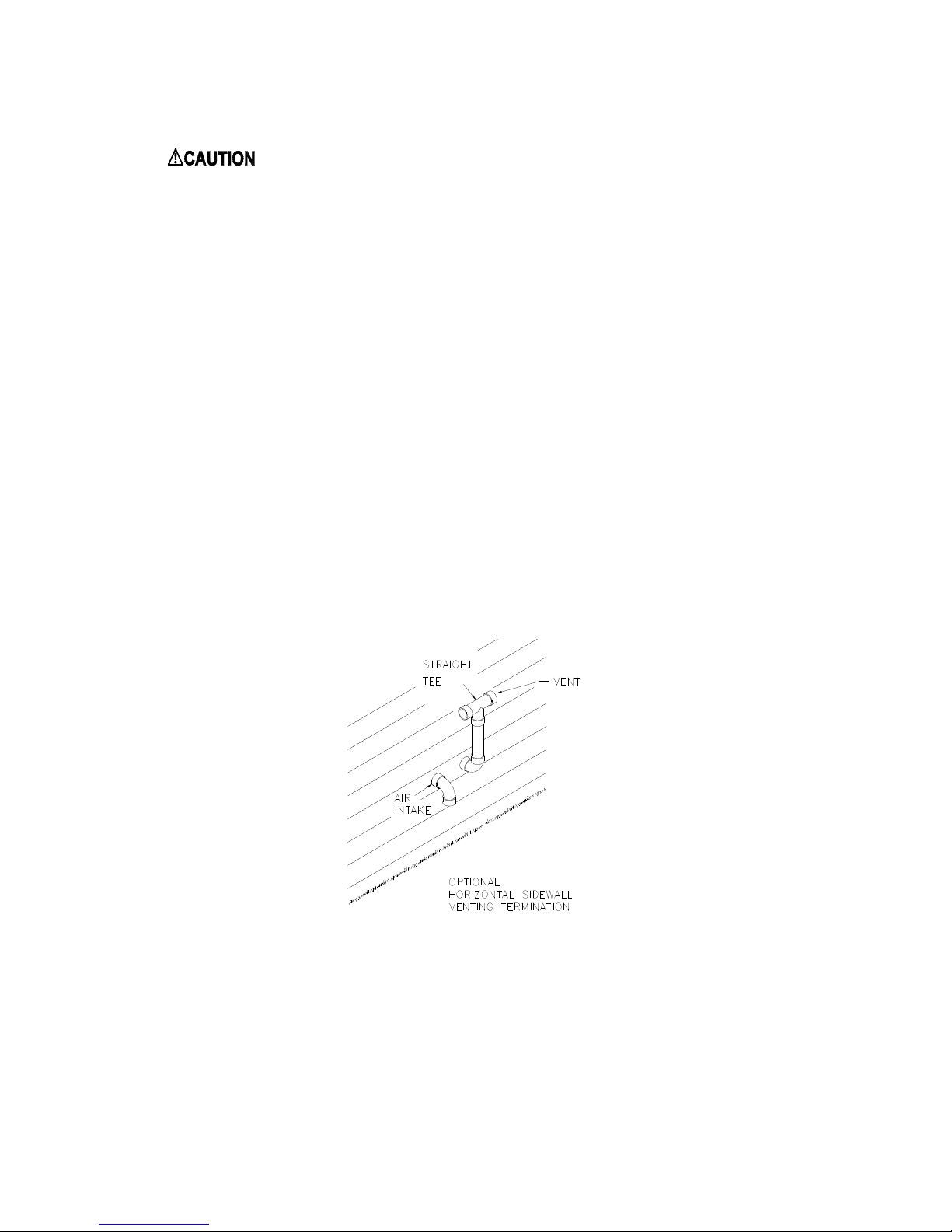
5. Alternate Vent Termination for Wind Gusts in Excess of 25 MPH
Figure 4: Optional Termination
If the exhaust vent is to be installed in a location which may be exposed to winds blowing directly at the
vent termination, this alternate configuration should be used. All previous venting instructions still apply,
with the exception that the elbow on the exhaust vent termination is replaced with a straight tee. A sanitary
tee may be used if a straight tee is unavailable, but optimal performance is achieved with a straight tee. The
air intake remains unchanged.
19
Page 20

All installations and services must be performed by qualified service personnel.
6. Optional Direct Vent Terminations
Three optional vent kits are available for direct vent terminations, refer to Figure 5.
•
The concentric vent kits (Thermo Products p/n AOPS7488 & AOPS7489) provide a means for the vent
and intake to be installed through a single opening in the roof or exterior wall. Kit p/n AOPS7488 is
used on furnace models CLHS1/CLHX1-50 & 75. Kit p/n AOPS7489 is used on furnace models
CLHS1/CLHX1-100 &125.
•
The sidewall vent cap (Thermo Products part no. 370191) is a cover installed over the exhaust vent and
air intake pipes on the exterior of the building. For horizontal sidewall vent applications only. This kit
may be used on any size furnace in the CLHS1/CLHX1 family.
370191
SIDE WALL VENT KIT
HORIZONTAL
AOPS7488 / AOPS7489
CONENTRIC VENT KIT
VERTICAL
Figure 5: Optional Direct Vent Kits for the CLHS1 / CLHX1 Model Series of Furnaces
Install these optional kits according to the instructions provided with each kit. In horizontal or side wall
installations. The location and clearance requirements are identical to those of the standard vent
terminations described in this manual.
NOTICE: When using these alternate termination kits the furnace is more susceptible to a nuisance shut off
due to high winds blowing directly into the vent and changing the internal pressure enough to activate a
safety pressure switch. It is best practice to locate the vent so that prevailing winds do not blow directly into
the open vent termination.
F. CONNECTING FURNACE TO ROOF VENT / INTAKE TERMINATIONS
If it is not desirable, or feasible, to vent the furnace through a sidewall, it may be vertically vented through the
roof. Installation shall conform to the following guidelines, which are illustrated in Figure 6, below.
1. The outlet of the exhaust vent and the inlet of the combustion air intake, i.e. the terminations, shall be a
minimum of 12-inches above highest anticipated snow level.
2. The exhaust vent outlet must be installed a minimum of 12-inches above the air intake inlet.
3. Where exposed to prevailing winds, the combustion air intake shall be installed upwind of the vent outlet.
20
Page 21

All installations and services must be performed by qualified service personnel.
4. The exhaust vent and combustion air intake shall be a minimum of 3-inches and a maximum of 24 inches
apart.
NOTICE: When the vent termination is installed correctly, a draft should NOT be present in the system
during the furnace off-cycle.
Figure 6: Typical Rooftop Vent and Air Intake Termination Construction Details
G. CONNECTING FURNACE TO VENT / INTAKE TERMINATIONS
1. Figure 7 depict typical exhaust vent and air intake connections for the furnace model series CLHS1 /
CLHX1, as well as a list of required parts to correctly install each system.
For the -100 & -125 models, which require 3-inch PVC pipe, there will still be a short section of 2-inch
PVC pipe & fittings at the furnace, as the grommet and intake flange are both sized for 2-inch. The length
of 2-inch PVC pipe between the furnace cabinet and the 2-inch x 3-inch reducer fitting must be kept to a
minimum. The maximum length of that 2-inch PVC pipe should be 12 inches.
21
Page 22

All installations and services must be performed by qualified service personnel.
Figure 7: Required Exhaust Vent and Air Intake Piping
2. Connecting The Exhaust Vent To The Inducer
a. The Exhaust Vent piping may exit the furnace thru either the top, left or right side as depicted in Figure
7. Upon selection of the location to exit the furnace, cut out the appropriate knock-out and install the
rubber grommet provided. The grommet should be installed from the inside so that the insulation is
captured between the flange of the grommet and the metal panel. All PVC connections inside the
cabinet should be sealed with silicone caulk to enable easy disassembly for future repairs.
b. If the Vent is going through the Top panel, connect a 2-inch 90° PVC street elbow to the flexible drain
adapter already installed on the inducer blower. Tilt the street elbow so it is installed at a 45° angle
from the vertical. Tighten the worm clamp on the flexible drain adapter to seal and hold the elbow in
place. Then connect a 2-inch 45° PVC street elbow to the previously installed elbow so that it points up
toward the top panel. Now a section of 2-inch PVC pipe can be installed through the rubber grommet in
the top panel into the 45° street elbow.
22
Page 23

All installations and services must be performed by qualified service personnel.
c. If the Vent is going thru the Left side panel, remove the Door Latch Channel and its 4 screws. Then
remove the Inducer Blower and the 4 nuts & washers which attach it. The Inducer Blower should then
be rotated 180° and re-installed. Do not over-tighten the 4 nuts which attach the inducer, as that may
cause the inducer’s internal blower wheel to rub. Replace the 5/16” ID tubing which ran from the
inducer to the pressure switch with the longer piece of tubing provided in the parts kit. Now re-install
the Door Latch Channel and its mounting screws. The flexible drain adapter that was factory installed
on the exit of the inducer must be retained at the exit of the inducer. Now a section of 2-inch PVC pipe
can be installed through the rubber grommet in the left panel into the flexible drain adapter. Tighten the
worm clamp on the flexible drain adapter to seal and hold the PVC pipe in place.
d. If the Vent is going thru the Right side panel, merely install a section of 2-inch PVC pipe through the
rubber grommet in the right panel into the flexible drain adapter. Tighten the worm clamp on the
flexible drain adapter to seal and hold the PVC pipe in place.
3. Connecting The Combustion Air Intake Piping
: Outside combustion air must NOT be drawn from an area directly adjacent to a pool, hot
tub or spa. Measures should be taken to prevent the entry of corrosive chemicals or vapors into the
combustion air supply. Such chemicals include but are not limited to chlorinated and/or fluorinated
hydrocarbons such as found in refrigerants, aerosol propellants, dry cleaning fluids, degreasers ,
bleaches, air fresheners or solvents. Vapors from such products can form reactive acid producing
chemical species when burned in a gas flame. Should acidic compounds form in the furnace they may
significantly reduce the useful life of the furnace.
a. The Combustion Air Intake piping may enter the furnace thru either the top, left or right side as
depicted in Figure 7. Upon selection of the location to exit the furnace, cut out the appropriate knockout and install the Intake Air Flange provided using 4 self-tapping screws.
b. A section of 2-inch PVC pipe should then be inserted into the Intake Air Flange, using silicone caulk to
seal the pipe to the flange. The pipe may protrude into the furnace up to 1 inch past the flange. For
increased rigidity, a self-tapping screw may be installed thru the flange into the PVC pipe.
H. CONDENSATE DRAIN LINE & TRAP ASSEMBLY
1. The following diagrams depict typical condensate drain and trap connections for the furnace models series
CLHS1 and CLHX1, refer to the illustrations in Figures 8a-8b and 9.
NOTICE: If the 11/16 inch tubing is difficult to slide through the rubber grommet, spray some mild soap or
light oil (such as WD-40) on the tube prior to pushing through the grommet to serve as a lubricant. Wipe off
excess after installation.
23
Page 24

All installations and services must be performed by qualified service personnel.
Figure 8a. Condensate Trap Assembly, Left Side
Figure 8b. Condensate Trap Assembly, Right Side
24
Page 25

All installations and services must be performed by qualified service personnel.
Figure 9. Condensate Trap Assembly, Left Side with Tubing Installed
2. Determine from which side of the furnace the condensate disposal lines will be run.
NOTICE: On the model series CLHS1 / CLHX1 the condensate disposal line must be on the opposite side
as the return air inlet. The return air cutout is sufficiently large to block normal placement of the condensate
trap and condensate lines.
Drive two (2) #8 x 3/4 inch sheet metal screws with black protective coating (supplied with furnace) to
attach the condensate trap to the furnace casing. Pilot holes are provided on both sides of the casing for
mounting the trap. After attaching the trap, rotate the black barb tee clockwise 90° so that the barbs are
horizontal.
3. Attach one (1) drain hose (a length of 11/16 inch O.D. clear, colorless tubing) from the drain port of the
Coil Front Cover plate through the rubber grommet (“E” in Figures 8a & 8b) in the side panel and connect
to one of the barbs of the condensate trap. Tubing should create a gentle bend with no kinks. Cut to length
as necessary and discard excess. Use the spring-type hose clamp(s) provided in the parts package to secure
all connections.
If the condensate trap is on the Left Side of the furnace, as in Figure 8a, the tubing from the Coil Front
Cover must be snapped into this bracket to hold it in place as shown in Figure 9. The tubing support
bracket may be temporarily removed to allow easier assembly of the tubing into the bracket, but it must be
reinstalled properly.
25
Page 26

All installations and services must be performed by qualified service personnel.
NOTICE: For condensate traps on the Left Side, failure to attach the support bracket or insert the tubing
properly may create a water trap in the tubing, leading to furnace shut-off as a result of a blocked
condensate drain.
4. Attach the second drain hose (a length of 11/16 inch O.D. clear, colorless tubing) from the lower port of the
Flexible Drain Adapter (“A” in Figures 8a & 8b) to the plastic hose barb tee provided in the condensate trap
assembly. Cut to length as necessary and discard excess. Attach the drain hose to the hose barb on the other
side of the condensate trap tee. Use the spring-type hose clamp(s) provided in the parts package to secure
all connections.
5. Plan, source, and install a condensate drain line using ½ inch diameter CPVC (chlorinated polyvinyl
chloride) thermoplastic pipe and pipefittings. In the event ½ inch PVC is preferred, a CPVC to PVC adapter
is included in the parts kit provided with the furnace. Route the line in the shortest possible manner to reach
a nearby drain. Secure all joints using cement. For gravity drainage, the condensate drain line must maintain
a minimum ¼ inch per foot downward slope toward the drain. The drain line must be watertight, supported,
and secured such that it cannot be easily moved.
NOTICE: If an air conditioning condensate drain line is combined with the furnace condensate drain line,
the air conditioning evaporator coil must have a separate trap installed ahead of the connection joint.
6. A condensate pump may be required when,
•
a suitable drain is not present,
•
the drain is above the trap outlet level on the furnace, or
•
the drain line cannot be sloped downward its full length to the drain.
7. CAUTION: Continual exposure to condensate may injure plants and damage certain building
materials, including many metals, wood, stone, and concrete.
Flue gas condensate is slightly acidic with a pH of about 3.5. (A pH level of 7.0 is considered neutral.
Carbonated cola drinks with a pH of 3.1 are actually slightly more acidic than condensate.) If local codes
require an acid neutralizing kit, a kit is available from Thermo Products under part no. 320095. Follow the
instructions enclosed with the neutralizing kit for proper installation.
8. The condensate piping in the furnace and the drain system should be flushed out at the start of every heating
season. This will ensure trouble free operation and will keep the acidity level well above a pH of 3.4, i.e.
more towards neutral.
To flush the condensate drain system, follow these steps.
a. Turn off electrical power to the furnace at the disconnecting switch and adjust the room thermostat to
“OFF”, or to the lowest temperature setting.
b. Flush the drain system by removing the drain hose from the Coil Front Cover of the secondary heat
exchanger and running tap water into the open end of the tubing. Run at least a quart of water through
the drain system, until the water leaving the drain system is clear and colorless in color and free of any
particulate matter.
c. Replace the drain tubing by pushing it firmly onto the nipple. Make sure the spring-type hose clamp is
returned to the original position to prevent leaks.
d. If any of the electrical controls are inadvertently wetted during the flushing process, dry them with a
soft cloth and wait 24 hours before operating the furnace.
26
Page 27

All installations and services must be performed by qualified service personnel.
e. Adjust the room thermostat to the “HEAT” position, or to the desired temperature, and restore
electrical power to the furnace.
9. If the condensate trap is not primed at the time the furnace is powered up, the furnace will run and
eventually produce enough condensate to cause the furnace to shut off. At that time the condensate will flow
out of the heat exchanger into the trap and the furnace will restart, resuming normal operation.
I. GENERAL GAS PIPING
: Because of the potential of odorant fade, a gas leak may not be detected by smell. If this
furnace is installed below grade, contact your gas supplier for a gas detector.
1. Left and right gas supply piping - These furnaces are set-up to be gas piped through either the left or right
side by using a nipple, elbow and a straight pipe.
2. A drip leg must be used on both LP and natural gas installations prior to the furnace in order to trap oil,
condensate and other impurities which might otherwise lodge in the gas valve or plug the burner orifice. Failure
to install a drip leg may void the limited warranty on the furnace.
3. A 1/8 inch NPT plugged tapping, accessible for test gage connection, must be installed immediately upstream of
the gas supply connection to the furnace.
4. If local codes allow the use of a flexible gas appliance connector, always use a new listed connector. Do not use
a connector which has previously serviced another gas appliance.
5. The furnace and its equipment shutoff valve must be disconnected from the gas supply piping system during any
pressure testing of that system at test pressures in excess of 1/2 psi (3.5 kPa).
Figure 10
27
Page 28

All installations and services must be performed by qualified service personnel.
: Care must be taken not to wet electronic components during leak test. Wetting the electronic
components may damage their circuitry and cause a hazardous situation. Dry moisture from all leads and
terminals if wetting occurs. Wait at least 24 hours for the circuit to fully dry before energizing the burner circuit.
J. REQUIREMENTS AND SIZING OF DUCT WORK
The duct system must be sized and installed by a qualified installer or service person, following the design standards
of the Air Conditioning Contractors of America (ACCA) or ASHRAE.
1. When it is located in the same room as the furnace, a return air register must be installed a minimum of 20 feet
away from the furnace.
2. When a furnace is installed so that supply ducts carry air circulated by the furnace to arears outside the space
containing the furnace, the return air shall also be handled by ducts(s) sealed to the furnace casing and terminating
outside the space containing the furnace.
3. The return air duct system must equal the supply air duct system in its capabilities. Use a supplier's catalog for
proper sizing of outlet and return air registers and grills to ensure that they meet the CFM requirements of the run to
which they are connected.
4. If the furnace is used in connection with an air conditioning evaporator coil, the furnace must be installed parallel
with or on the upstream side of the coil, to prevent condensation in the heat exchanger. If the evaporator coil is
installed with a parallel flow arrangement, dampers or other means to control flow of air should be installed to
prevent chilled air from entering the furnace. If such a device is manually operated, it must be equipped with a means
to prevent operation of either the furnace or air conditioner unless it is in the full heat or cool position.
We recommend that the outlet duct be equipped with a removable access panel to allow for visual inspection of the
heat exchanger to check for leakage or to allow for insertion of a probe sampler in the air stream. This removable
access cover should be attached to ensure there is no air leakage.
28
Page 29

All installations and services must be performed by qualified service personnel.
5. The duct system shall be sized for the maximum CFM requirement of the installation whether it is for heating or
cooling. Two common rules for heating and cooling follow:
A. COOLING: 400 CFM (1200 BTU's) per ton of cooling is typically required.
B. HEATING: 14 CFM of heating per 1,000 BTU's of furnace output based on a nominal temperature rise.
EXAMPLE:
Heating output of a furnace is 100,000 BTU: 100 x 14 CFM = 1400 CFM
Air conditioning installed is 4 tons: 4 x 400 CFM = 1600 CFM
NOTE: The duct system must be sized for the larger CFM requirement for cooling. If only 3 tons of cooling were
installed: 3 x 400 CFM = 1200 CFM. The duct would then have to be sized for the 1400 CFM heating requirement.
Figure 11
All trunk lines, take-offs, registers and grill-free areas must be figured when determining the air handling capacity of
a duct system. One can obtain the necessary duct system size by utilizing the chart below. (For example, see Figure
11.) Use a supplier’s catalog for proper sizing of outlet and return air registers to insure that the register will meet the
CFM requirements of the run to which it is connected.
The main trunk lines, take offs, registers and grills of the supply return air duct system must have an adequate square
inch area to move the desired CFM in order to achieve proper movement.
Each of the system components (trunk lines, take offs, runs and register and grill-free areas) must be properly sized
and matched together to ensure the necessary air handling capacity of a duct system. A 12" x 8" duct with a 400
CFM capacity for example will not flow 400 CFM if the register(s) to which it connects only flows a total of 200
CFM.
The speed of the blower motor may have to be changed to obtain the proper 45°F to 75°F temperature rise for
heating when an air conditioning coil is installed. This depends on the static resistance of an individual duct system
and the size of the air conditioner.
29
Page 30

All installations and services must be performed by qualified service personnel.
K. FILTERS
It is necessary to cut the return air opening in the casing depending upon the needs of the specific installation. It is
possible to cut the return air opening in either the left, right, back or bottom of the cabinet.
NOTICE: If your furnace will require air delivery above 1800 CFM it is advisable that both sides, or a combination
of 1 side and the back, be used.
This furnace has been factory supplied with a high quality re-usable filter rated for air velocities up to 600 ft/min. An
optional Thermo Pride filter rack assembly (part no. AOPS7547 for -050, -075 & -100 and AOPS7375 for -125)
is available which is sized for the filter provided. See Figure 12.
This filter should be inspected monthly. When dirty, the filter must be cleaned or replaced, if necessary, to assure
proper furnace operation. Follow the cleaning, removal and replacement procedure below.
NOTICE: If the furnace is installed in a home or structure being remodeled, dust levels may be much higher than
normal. The filter must be inspected daily and cleaned as needed until dusty conditions have been eliminated.
: This furnace is not to be used for temporary heating of buildings or structures under construction.
The filter rack or drop chute will be located between the return air plenum and the return air opening of the furnace.
Slide dirty filter out of the filter rack. Clean the filter by vacuuming, rinsing with tap water, hosing or dipping in an
ordinary detergent solution. Replace the completely dry filter in the rack.
If an optional Thermo Pride filter rack is used with the furnace, it will serve as a template to scribe a mark for the
return air opening on the casing. Place the filter rack on the casing 1 inch up from the bottom of the furnace on either
the Left or Right side of the cabinet. Align the back of the filter rack with the back of the cabinet, and place the
securing flange against the casing for locating the return air opening.
NOTICE: While scribing the return air opening, the filter rack can be held into position by tape or similar means.
Position the open end of the filter rack so that it is accessible for filter replacement. Once the filter rack is positioned
correctly, scribe a line along the inside of the securing flange of the filter rack on three of the sides. To scribe a line
on the fourth side, on the open end, use the open end support for a guide. Remove the filter rack and cut the return
air opening in the casing.
Now the filter rack can be permanently attached to the furnace with screws or pop-rivets along the securing flange.
Connect the return plenum to the filter rack and slide the filter into place.
Figure 12
30
Page 31

All installations and services must be performed by qualified service personnel.
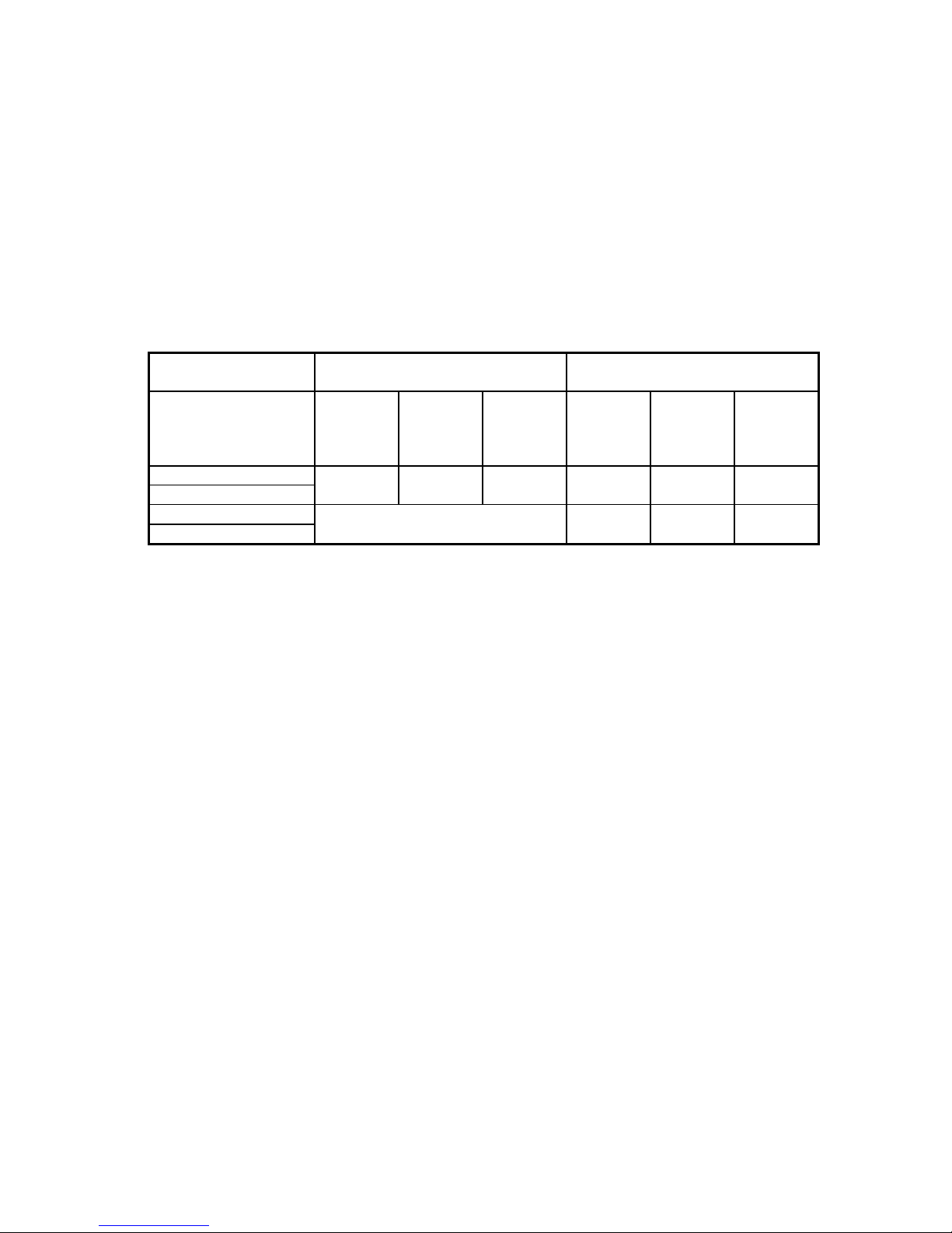
Use of Non Thermo Pride Filter Retention Means
If a method other than the Thermo Pride filter rack is selected for retention of the filter and/or use of a different filter
type is desired, see Table 3 for minimum size guidelines for selecting a filter system for the CLHS1 or CLHX1
furnaces.
MINIMUM FILTER AREA REQUIRED (LENGTH X WIDTH)
FILTER TYPE MAX.
RATED
VELOCITY
-050 -075 -100 -125
THERMO PRIDE *
SUPPLIED
PERMANENT FILTER
STANDARD
PERMANENT FILTER
DISPOSABLE TYPE
FILTER
* The Thermo Pride supplied filter can be cut to size to fit other filter retention systems as long as the minimum size
requirement is met. NOTICE: Any internal stiffeners used in the filter must not be removed, although they can be cut
to size as needed.
NOTICE: The filter areas in Table 3 are the minimum areas required based on the CFM generated by the furnace
for standard heating speeds only. The following formula can be used to determine the minimum filter area required
for cooling if the unit is equipped with cooling. This value should then be compared to the value shown in Table 3
and the larger of the two should then be used for determining the minimum filter area required for that installation.
FORMULA:
(tons of cooling) x (400 CFM per ton) x (144 square inches per foot) = filter area in sq.inches
(max. rated velocity of filter from Table 3 for the filter type)
EXAMPLE:
If you have a CLHS1-100 furnace with 4 tons of cooling and a standard permanent filter.
4 tons x 400 CFM x 144 = 460 square inches for cooling
500 fpm
For heating, a CLHS1-100 needs 422 square inches of filter. The filter system must be designed for the larger CFM
requirement determined for cooling of 460 square inches. A filter would have to be sized so that the area (length X
width) was at least 460 sq. in.
L. WIRING
All wiring shall be performed by a qualified electrician or service person. The wiring must comply with local codes,
the instructions in this manual, and in the absence of codes with the National Electrical Code (ANSI/NFPA-70 or
latest edition).
1. The following items are guidelines to complete the wiring portion of the installations.
600 FT/MIN 176 IN2 264 IN2 352 IN2 440 IN2
500 FT/MIN 211 IN2 317 IN2 422 IN2 528 IN2
300 FT/MIN
EQUATION: REQUIRED CFM / MAX. RATED VELOCITY X
144 = FILTER AREA (IN2)
HEATING VALUES PROVIDED IN CHART BELOW
352 IN2
TABLE 3
528 IN2 704 IN2 880 IN2
31
Page 32

All installations and services must be performed by qualified service personnel.
a. A separate power supply circuit with over current protection and a disconnect switch must be provided. See
furnace specifications or furnace rating label for maximum fuse size.
b. All CLHS1 and CLHX1 Series furnaces are supplied with a fuse disconnect switch box to be mounted on the
outside surface of the right or left side casing so a fuse disconnect can be mounted on the furnace. Make the 120
volt supply connection in this junction box. A green screw and a strain relief are provided in order to connect the
power supply ground wire and provide strain relief for the 120 volt power leads from the furnace in the fuse
disconnect box. A disconnect switch can be field mounted on the 2x4 box provided. If not, the disconnect switch
must be located reasonably close to and within sight of the furnace.
NOTICE: The hot surface igniter and operation of this furnace depends on correct polarity. The hot leg of the
supply circuit must be connected to the black line lead and the common leg to the white line lead in the field
mounted junction box. The hot leg must pass through the disconnect switch in all cases to prevent the hazard of
electrical shock when servicing.
IMPORTANT: The furnace must be grounded in accordance with local codes and with the National Electrical Code
(ANSI/NFPA NO. 70 or latest edition).
2. Electronica Air Cleaner (EAC) and Humidifier Installation
The ignition module on this furnace has designated terminals to control the operation of an electronic air cleaner
and/or humidifier. These terminals provide line voltage (1.0 Amp @ 120VAC) for the control of these accessories
(See Figures 13 & 14). The Humidifier is energized whenever the combustion inducer motor is energized. The EAC
is energized whenever the circulation blower motor is energized for heating or cooling, but not for continuous fan.
NOTICE: It is important to confirm that the operating voltage of the humidifier or EAC being installed matches the
output of this control. If not, a field supplied relay or transformer may be necessary to provide the proper control and
supply voltage for the accessory being installed. See the manufacturer’s instructions for the humidifier or EAC for
additional instructions.
3. Thermostat Anticipator Setting
When using an analog thermostat, proper control of the indoor temperature can only be achieved if the thermostat is
calibrated to the heating and/or cooling cycle. A vital consideration of this calibration is related to the thermostat
heat anticipator. Newer digital thermostats do not have an Anticipator Setting and do not require calibration.
The proper thermostat heat anticipator setting is 0.4 Amps for furnace operation only. To increase length of cycle,
increase setting of heat scale; to decrease length of cycle, decrease setting of heat scale. Anticipators for the cooling
operation are generally pre-set by the thermostat manufacturer and require no adjustment. Anticipators for the
heating operation are of two types, pre-set and adjustable. Those that are pre-set will not have an adjustment scale
and are generally marked accordingly.
32
Page 33

All installations and services must be performed by qualified service personnel.
4. CLHS1 (Single Stage) Blower Motor Speed Wiring
Figure 13
: TURN OFF THE ELECTRICAL POWER to the furnace before attempting to change blower
speed wiring.
A. The furnace is factory wired to the ignition control with standard heating and cooling speeds. When changing
motor speeds, simply switch the needed speed to either the heating or cooling terminal as applicable on the
module to obtain the desired CFM. The unused speeds should then be reconnected to the module in the “park”
positions.
B. The optional blower delay jumpers on the integrated control (Figure 13) are used to determine the length of the
heat delay–to-fan-off periods. The delay-to-fan-on period is preset and non-adjustable. The available options for
the delay-to-fan-off are as follows: 60, 90, 120 & 180 sec.
The factory default for optimum performance of the delay-to-fan-off period is 90 seconds.
33
Page 34

All installations and services must be performed by qualified service personnel.
5. CLHX1 (Two Stage) Blower Motor Speeds
Figure 14
: TURN OFF THE ELECTRICAL POWER to the furnace before attempting to change blower
speed wiring.
A. The selection of blower motor speeds for the CLHX1 is made through the use of jumpers on the integrated
control (Figure 14). There are jumpers for each of the following functions: Heat, Delay, Cool and Adjust. Each
function has 4 selections: A, B, C and D. The default setting for each function is as follows:
Function Default
Heat C
Delay A
Cool D (125k unit default setting C)
Adjust A
B. The 4 Heat & 4 Cool functions are the predefined blower speeds listed in the specifications Section II, B.
C. The Adjust function is a slight increase or decrease in all blower speeds, as follows:
Jumper Adjustment
A None
B +10%
C -10%
34
Page 35

All installations and services must be performed by qualified service personnel.
D Do Not Use (Test Mode)
D. The Delay function is for the Blower-Off delay during cooling only. Once the thermostat has satisfied the call
for cooling, the blower will continue to run at 82% of the selected speed for the delay period. The selections are
follows:
Jumper Delay-Off
A 30 sec.
B 45 sec.
C 60 sec.
D None
There is a predefined Blower-On ramp function for cooling only. Upon the thermostat call for cooling, the
blower will run at 50% for 30 sec. after which it will run at 82% for the next 30 sec. Then the blower will run at
100% of the selected cooling speed until the thermostat is satisfied.
E. The optional blower delay jumpers on the integrated control (Figure 14) are used to determine the length of the
heat delay–to-fan-off periods. The delay-to-fan-on period is preset and non-adjustable. The available options for
the delay-to-fan-off are as follows: 60, 90, 120 & 180 sec.
6. Field Wiring and Replacement Wiring
Field wiring between the furnace and devices not attached to the furnace shall conform with the temperature
limitation for Type T wire [63°F rise (35°C)] when installed with the manufacturer’s instructions. If any of the
original factory supplied furnace wiring is replaced, or a separate device other than the thermostat is wired internal to
the unit, 105°C thermoplastic or equivalent wire must be used.
M. ADDITIONAL FEATURES
1. Heat Staging
The CLHX1 furnace control board has the option of selecting the preferred method for the activation of the second
stage of heating. Selections are made with a jumper at the P5 terminal strip (see Figure 14). The selections available
are as follows: OFF, 10, 15 & 20. The default selection is OFF.
Selecting 10, 15 or 20 will enable the furnace to activate second stage heating once it has run for 10, 15 or 20
minutes at the low stage. Selecting the OFF position will require that the furnace received a call for W2 heat from the
thermostat to enable the second stage of heating.
2. Thermostat Call for Fan
When the thermostat calls for continuous fan (G) without a call for heat or cooling, the indoor fan is immediately
energized according to the jumper setting on P17 (see Figure 14). The jumper selection offers 5 speeds for
continuous fan (VS G, High Cool, Low Cool, High Heat and Low Heat). VS G indicates that the control should use
the pre-programmed Variable Speed for G, which is 50% of the selected High Cool speed.
3. Dehumidifier (Dehum) and Heat Pump
The CLHX1 furnace control board has jumpers which should be used to indicate the presence of a dehumidifier, or
operation with a heat pump. A jumper is provided for each option, and available selections are marked YES and NO.
35
Page 36

All installations and services must be performed by qualified service personnel.
IV. STARTING THE UNIT
A. SEQUENCE OF OPERATIONS
36
Page 37

All installations and services must be performed by qualified service personnel.
B. INITIAL START UP
This furnace does not have a pilot. It is equipped with a hot surface igniter, which automatically lights the burner. Do
not attempt to light the burner by hand. Check the following items before the initial start-up.
1. Check all wiring for loose connections and proper hook up.
2. Leak test gas piping connections.
37
Page 38

All installations and services must be performed by qualified service personnel.
3. Check all tubing to the pressure switch and drain, making sure they are connected firmly at all connection
points.
4. Check flue pipe, combustion air inlet and all PVC connections for tightness and to ensure there is no blockage.
5. Make sure air filter is in place.
6. Make sure the outside vent and air intakes are installed according to instructions and are free from blockage.
7. Make sure that the drain trap is properly connected to the furnace and to the buildings drain system.
8. Make sure that the combustion door is properly installed.
9. Prime the condensate trap by adding water through a drain hose to expedite the setup & startup process.
: Turn off power to furnace before it is placed into service. The gas piping system must have been
leak tested by a qualified heating contractor. (See Section III, J, of these instructions on the installation of gas
piping).
: It may be necessary to purge the air out of the gas line for initial start-up of the furnace after
installation. This should be done by a qualified heating contractor. If excessive gas escapes when purging the gas
supply at the union, allow the area to ventilate for at least 15 minutes before attempting to start the furnace. LP
gas is especially dangerous because the specific gravity of LP gas allows it to accumulate at floor level at a
dangerous concentration. For remainder of operating instructions, reference Users Information Manual.
: Heat exchanger oil will burn off on initial firing creating an unpleasant odor. To prevent this
odor from occurring more than once, it is suggested that:
1. A window(s) be opened.
2. The thermostat be set at highest setting.
3. The furnace remain running at conditions 1&2 for 30 minutes or until odor has dissipated.
C. ADJUSTMENT OF BTU INPUT RATE
The Orifice for this furnace was sized: 1) for natural gas having a heating value of 1025 BTU per cubic foot and a
specific gravity of 0.65, or 2) for liquefied propane gas with a heating value of 2,500 BTU per cubic foot and a
specific gravity of 1.55. The information plate inside the furnace vestibule will specify which gas your furnace is
setup to use. If the furnace is installed at an altitude that is more than 2,000 feet above sea level, it is mandatory that
the input to the burner be reduced 4.0% for every 1,000 feet that it is above sea level. If the furnace is installed at an
elevation of 5,000 feet, its input must be reduced 20.0%. Example: a furnace rated at 100,000 BTU at sea level must
be reduced to a firing rate of 80,000 (100,000 x 0.80 = 80,000) at an elevation of 5,000 feet. If the furnace is
installed at an elevation of 2,000 feet or less, no reduction in input is required. If installed above 2,000 feet, the
furnace installer should contact Thermo-Products for replacement orifices.
To check the input of your natural gas furnace, allow the unit to operate for 10 to 15 minutes and proceed as follows:
a. Call your gas supplier and ask for the BTU content (heating value) of one cubic foot of the gas, supplied to
the installation area. An alternate approach is to assume a value of 1025 BTU/Cu Ft, which is the national
average.
b. With all other gas appliances turned off and using a stopwatch, clock the time required for the dial on the
gas meter to make one full revolution. The meter will state how many cubic feet has flowed for one
revolution; usually one, two or five. The unit must have been in operation at least 10 minutes before
clocking.
FORMULA: BTU Content x Number of CU FT x 3600 / Time Required for Revolution = Input BTU/Hr
EXAMPLE:
The gas meter reads 2 CU FT per revolution, and it takes 74.8 sec. to complete 1 revolution.
1025 BTU/CU FT x 2 CU FT x 3600 / 74.8 sec. = 98,663 BTU/Hr
38
Page 39

All installations and services must be performed by qualified service personnel.
Check for the model number of this furnace, its input, the type of gas and the manifold pressure on the
information plate located on the vestibule panel behind the upper front panel. In the example above, if the
furnace was a CLHS1-100 model, then the 98,663 BTU input would be acceptable because it was within 2% of
the listed input of 100,000 BTU.
Make sure that the gas supply pressure to the furnace falls within the maximum range of 4.5” to 14.0” w.c.
pressure on natural gas and 11.0” to 14.0” w.c. on Propane gas. The pressure to the furnace must be checked
while the furnace burner and any other gas appliances on the same supply system are operating.
GAS PRESSURE CHART FOR ALL CHLS1 & CLHX1 MODEL FURNACES
Fuel Gas Type Propane Natural
Operating Mode and
Model Series
Normal Manifold
Pressure (in. W.G.)
Maximum Gas Supply
Pressure (in. W.G.)
Minimum Gas Supply
Pressure (in. W.G.)
This gas furnace is equipped with a fixed orifice sized for the manifold pressure shown on the information plate. The
input should only be increased or decreased by adjusting the manifold pressure. Remove the 1/8" threaded pipe plug
located on the manifold and connect a U-Tube manometer or pressure gage to measure the pressure.
High Fire
10.0 ± 0.3 5.0 ± 0.3 3.5 ± 0.3 1.8 ± 0.3
TABLE 4
CLHX1
Low Fire
14 14
11 4.5
High Fire
CLHX1
Low Fire
To adjust the pressure, remove the brass regulator screw cover from the regulator on the outlet side of the gas valve
and using the adjustment screw. Refer to Figure 15, Two stage regulator shown. Decrease the pressure by turning the
screw counterclockwise or increase it by turning the screw clockwise. ADJUSTMENTS TO THE LISTED
PRESSURE MUST NOT EXCEED THE VALUES IN TABLE 4. Replace screw cover when adjustment is
complete. The correct input can be assumed if the furnace manifold pressure is the same as that shown on the
information label if a gas meter is not available for natural gas, or the unit is installed on liquefied petroleum gases
which are not metered.
Shut off the gas supply to the furnace. Remove the pressure gage and re-install the pipe plug using a thread
compound resistant to the action of Liquefied Petroleum gases. If the rated input cannot be obtained with the present
orifice at the correct pressure, your installer should contact Thermo Products to assist in sizing the proper orifice.
Figure 15
39
Page 40

All installations and services must be performed by qualified service personnel.
Our Engineering Department will gladly assist in sizing the orifice if you provide them with the heating value in
BTU per cubic foot and the specific gravity of the gas.
D. BURNER ADJUSTMENT
This unit is designed to require no burner adjustment. Flames should be visually examined at the start of the heating
season and monthly during the heating season. The flames should be checked by looking through the sight glass in
the combustion door and observing the flames inside the burner box. Burner flames should be clear, blue and almost
transparent in color. (See Figure 16). Burner flames should not impinge or fire against the side of the tube opening.
NOTE: It is not unusual to have orange tipped flames visible in the tube for Propane gas.
Figure 16
: These furnace models are an in-shot burner design, which does not require an air shutter
adjustment (air shutters are not used) for proper flame characteristics. Combustion door should always be in
place when operating furnace.
E. FURNACE CHECKOUT PROCEDURE
Before any system of gas piping is finally put into service, it shall be carefully tested to assure that it is gas tight as
indicated in the manual.
NOTICE: All controls on the unit should be checked for proper functioning prior to the qualified service personnel
leaving the job site. Specifically the following should be checked:
With furnace in normal heating operation, check to make certain blower will start and stop automatically under
control of integrated fan control.
1. Check safety limit control as follows:
a. Shut off incoming power.
b. Block return air opening or disconnect blower motor leads.
c. Restore power to furnace.
d. Set thermostat above room temperature calling for heat.
e. When temperatures are reached in furnace at limit control setting with blower out of operation, burner
should shut off.
f. Shut off electrical power.
IMPORTANT: Remove blockage or reconnect blower motor and restore power.
2. Make certain thermostat will automatically start and stop furnace.
3. Block the PVC flue outlet gradually with a flat piece of metal, until the pressure switch functions shutting off the
main burners.
40
Page 41

All installations and services must be performed by qualified service personnel.
4. Block the PVC air inlet gradually with a flat piece of metal until pressure switch functions shutting off the main
burners.
IMPORTANT: Remove flue & air inlet blockage when done.
5. Remove the blower door with the house air blower operating. The door interrupt switch is in the 120 volt circuit
and will shut down the entire system. Replace the blower door and the blower will resume operation.
V. INSTALLER'S INSTRUCTIONS TO USER:
After completing the installation, the installer shall inform and/or demonstrate to the homeowner:
1. The location of all the instructions in the furnace and that these instructions and the users information manual
must be kept along with instructions for any accessories in the plastic pouch on the outside of the furnace.
2. The location and use of the manual gas shut off valve and furnace electrical disconnect switch. Instruct user to
always shut off gas before shutting off electric power.
3. The sequence of operation of the furnace.
4. The correct operation and maintenance of the appliance as outlined in the users information manual.
5. That failure to maintain and operate this furnace in accordance with these instructions could result in hazardous
conditions, bodily injury, property damage and may void the limited warranty on the furnace.
6. Review with and encourage the user to read the label reproductions and all warnings and instructions outlined on
the front cover and in sections I, II and III of this manual and in the Users Information Manual.
7. Recommend that the user have a qualified heating contractor inspect the furnace at the start of each heating
season. Inform the user of the frequency of inspection required for each item in Section III of the User’s Manual.
VI. TROUBLESHOOTING
NOTICE: Before troubleshooting, familiarize yourself with the startup and checkout procedures.
To assist you in troubleshooting this furnace, it is equipped with an integrated ignition control with diagnostics.
These diagnostics evaluate what control system has experienced a failure and will activate a flashing light on the
control in different sequences to help pinpoint the failure which has occurred.
IMPORTANT: For your convenience, Thermo Products has installed a sight glass in the blower door of this
furnace. The number of flashes in groups should be observed through this sight glass and recorded before turning off
power to the furnace. Pressing the “Last Error” button on the control board will initiate the display of the last 5
failure codes, even if the furnace power has been shut off.
DIAGNOSTIC FEATURES
The integrated control continuously monitors its own operation and the operation of the system. If a failure occurs,
the LED will indicate a failure code as shown below. If the failure is internal to the control, the light will stay on
continuously. In this case, the entire control should be replaced, as the control is not field-repairable.
41
Page 42

All installations and services must be performed by qualified service personnel.
If the sensed failure is in the system (external to the control), the LED will flash in the following flash-pause
sequences to indicate failure status (each flash will last approximately 0.25 seconds, and each pause will last
approximately 1 second).
CLHS1 (Single Stage Furnaces)
LED Off - No power to control, pushbutton switch pressed, or control fault
LED steady ON (Any color) - Control hardware fault detected
Slow Green flash - No call for heat, no active errors
Slow Orange flash - Call for heat present, no active errors
1 RED flash - High limit switch open
2 RED flashes - Pressure switch open with inducer on
3 RED flashes - Pressure switch closed with inducer off
4 RED flashes - 1 hour lockout code
5 RED flashes - Incorrect line voltage polarity or incorrect polarity on 24 VAC line from transformer
6 RED flashes – Too many limit trips in one call for heat
7 RED flashes – Pressure switch cycle lockout
8 RED flashes - Too many flame dropouts detected
9 RED flashes – Not Used
10 RED flashes – Flame present with gas valve off
Rapid flash – Incorrect 24 VAC phasing/twinning error
CLHX1 (Two Stage Furnaces)
LED Off - No power to control, pushbutton switch pressed, or control fault
LED steady ON (RED) - Control hardware fault detected
Slow GREEN flash - No call for heat, no active errors
Slow ORANGE flash - Call for heat present, no active errors
Fast ORANGE flash - Call for heat present, Low Flame Current (below 1.5uA)
1 RED flash - Flame present with gas valve off
2 RED flashes - Pressure switch closed with inducer off
3 RED flashes – 1st stage pressure switch open with inducer on
4 RED flashes – Limit/Rollout switch open
5 RED flashes – Limit/Rollout open more than 15 minutes
6 RED flashes - Pressure switch cycle lockout
7 RED flashes – 1-hour Lockout code
8 RED flashes - Lockout due to too many flame dropouts
9 RED flashes - Incorrect line voltage polarity or incorrect polarity on 24 VAC line from transformer
10 RED flashes – Gas valve fault code
11 RED flashes – Limit/Rollout switch open from 5 to 15 minutes
12 RED flashes – Opened/damaged HSI (not available on 1171-121 model)
13 RED flashes – 2nd stage pressure switch open with high speed inducer on
4 ORANGE flashes – Y thermostat demand without G thermostat demand
: Power must be disconnected before servicing.
42
Page 43

All installations and services must be performed by qualified service personnel.
TROUBLESHOOTING GUIDE
THE SYSTEM IS STARTED BY SETTING THE THERMOSTAT TO CALL FOR
HEAT. THE FOLLOWING SHOULD HELP ESTABLISH THE TYPE OF
MALFUNCTION OR DEVIATION FROM THE NORMAL OPERATION.
TO USE THIS DIAGRAM, YOU JUST NEED TO FOLLOW THE INSTRUCTIONS IN THE BOXES.
TURN THERMOSTAT TO CALL FOR HEAT
DOES THERMOSTAT MAKE CONTACT?
No
Yes
Yes
IS ROOM TEMPERATURE
BELOW THERMOSTAT
SETTING?
Yes
IS THE TRANSFORMER
SUPPLYING 24 VOLTS
TO THE THERMOSTAT?
Yes
REPLACE
THERMOSTAT
No No
ABOVE 90 DEGREES F?
COOL THE THERMOSTAT
No
ARE WIRES CONNECTED
IS INTERNAL DAMAGE
REPLACE TRANSFORMER
IS ROOM
TEMPERATURE
Yes
PROPERLY?
Yes
PRESENT ON THE
TRANSFORMER?
Yes
No
TURN T'STAT
SETTING ABOVE
ROOM TEMP.
CORRECT WIRE
No
CONNECTIONS
CHECK INPUT
POWER, DOOR
INTERLOCK,
SERVICE SWITCH
AND FUSES.
IS THE INDUCER
BLOWER OPERATING?
Yes
No CHECK FOR
IS THERE 24 VOLTS
ACROSS "TH" & "TR"
AT THE INTEGRATED
CONTROL MODEL?
Yes
No
CONTINUITY
& PROPER
CONNECTIONS
43
Page 44

All installations and services must be performed by qualified service personnel.
44
Page 45

All installations and services must be performed by qualified service personnel.
45
Page 46

All installations and services must be performed by qualified service personnel.
46
Page 47

All installations and services must be performed by qualified service personnel.
Appendix –A Replacement Parts List``
47
Page 48

All installations and services must be performed by qualified service personnel.
48
Page 49

All installations and services must be performed by qualified service personnel.
49
Page 50

All installations and services must be performed by qualified service personnel.
50
Page 51

All installations and services must be performed by qualified service personnel.
Appendix – B Wiring Diagrams
1. CLHS1-050, -075, -100 and -125 with PSC Blower Motor
51
Page 52

All installations and services must be performed by qualified service personnel.
2. CLHS1-050, -075, -100 and -125 with Constant Torque Blower Motor
52
Page 53

All installations and services must be performed by qualified service personnel.
3. CLHS1-050, -075, -100 and -125 with ECM Blower Motor
53
Page 54

All installations and services must be performed by qualified service personnel.
Appendix C – Speed Specifications
CLHS1-050P (Single Stage with PSC blower motor)
Alterations Req'd For A/C @ Design External Static Pressure
Cooling Unit HTG Speed Recommended CLG Speed
18,000 Med Low (Blue) Low (Red)
24,000 Low (Red) Med Low (Blue)
30,000 Low (Red) Med High (Yellow)
36,000 Low (Red) High (Black)
Temperature Rise (°F)
Speed Tap 0.1 0.2 0.3 0.4 0.5 0.6 0.7
Low (Red) 67 69 75 83 97 119 146
Med Low (Blue) 47 49 51 54 60 66 73
Med High (Yellow) 37 38 40 43 47 51 58
High (Black) 28 29 31 34 38 42 48
External Static Pressure (in WC)
Airflow (CFM)
External Static Pressure (in WC)
Speed Tap 0.1 0.2 0.3 0.4 0.5 0.6 0.7
Low (Red) 653 633 583 528 452 370 301
Med Low (Blue) 926 901 855 812 733 669 599
Med High (Yellow) 1176 1145 1097 1012 943 866 761
High (Black) 1593 1507 1405 1293 1150 1044 915
Current (A)
External Static Pressure (in WC)
Speed Tap 0.1 0.2 0.3 0.4 0.5 0.6 0.7
Low (Red) 3.7 3.6 3.5 3.4 3.3 3.3 3.3
Med Low (Blue) 4.7 4.5 4.3 4.2 4.1 3.9 3.8
Med High (Yellow) 5.6 5.3 5.1 4.9 4.7 4.5 4.3
High (Black) 7.2 6.9 6.6 6.2 6.0 5.8 5.6
Power (W)
External Static Pressure (in WC)
Speed Tap 0.1 0.2 0.3 0.4 0.5 0.6 0.7
Low (Red) 362 358 350 343 337 332 326
Med Low (Blue) 473 461 446 436 418 403 394
Med High (Yellow) 588 563 537 514 498 477 453
High (Black) 777 739 705 668 640 613 586
Note: Shading indicates recommended operating range for heating.
54
Page 55

All installations and services must be performed by qualified service personnel.
CLHS1-075P (Single Stage with PSC blower motor)
Alterations Req'd For A/C @ Design External Static Pressure
Cooling Unit HTG Speed Recommended CLG Speed
24,000 Med Low (Blue) Low (Red)
30,000 Med High (Yellow) Med Low (Blue)
36,000 Med Low (Blue) Med High (Yellow)
42,000 Med Low (Blue) * High (Black)
* This speed not recommended at static pressures of 0.3 in WC or less
Temperature Rise (°F)
External Static Pressure (in WC)
Speed Tap 0.1 0.2 0.3 0.4 0.5 0.6 0.7
Low (Red) 95 95 95 97 101 104 113
Med (Blue) 69 69 69 70 74 80 87
Med High (Yellow) 44 46 49 51 55 64 70
High (Black) 38 40 44 47 50 57 64
Airflow (CFM)
External Static Pressure (in WC)
Speed Tap 0.1 0.2 0.3 0.4 0.5 0.6 0.7
Low (Red) 696 697 694 680 656 635 582
Med (Blue) 952 954 958 941 890 828 757
Med High (Yellow) 1509 1428 1344 1281 1193 1034 941
High (Black) 1743 1647 1516 1405 1318 1165 1024
Current (A)
External Static Pressure (in WC)
Speed Tap 0.1 0.2 0.3 0.4 0.5 0.6 0.7
Low (Red) 7.0 6.9 6.7 6.5 6.3 6.1 5.9
Med (Blue) 7.8 7.5 7.3 7.0 6.5 6.2 6.0
Med High (Yellow) 8.8 8.3 7.8 7.5 7.1 6.6 6.4
High (Black) 10.2 9.9 9.7 9.5 9.4 9.2 9.0
Power (W)
Speed Tap 0.1 0.2 0.3 0.4 0.5 0.6 0.7
Low (Red) 530 528 524 518 509 498 484
Med (Blue) 635 625 612 594 558 536 517
Med High (Yellow) 793 749 709 682 648 596 575
High (Black) 892 856 820 793 770 731 705
Note: Shading indicates recommended operating range for heating.
External Static Pressure (in WC)
55
Page 56

All installations and services must be performed by qualified service personnel.
CLHS1-100P (Single Stage with PSC blower motor)
Alterations Req'd For A/C @ Design External Static Pressure
Cooling Unit HTG Speed Recommended CLG Speed
30,000 Med Low (Blue) Low (Red)
36,000 Med High (Yellow) Med Low (Blue)
42,000 Med Low (Blue) Med High (Yellow)
48,000 Med Low (Blue) High (Black)
Temperature Rise (°F)
External Static Pressure (in WC)
Speed Tap 0.1 0.2 0.3 0.4 0.5 0.6 0.7
Low (Red) 89 88 85 88 93 103 111
Med (Blue) 62 61 62 65 69 78 92
Med High (Yellow) 47 48 50 56 60 66 77
High (Black) 40 43 46 50 55 60 67
Airflow (CFM)
External Static Pressure (in WC)
Speed Tap 0.1 0.2 0.3 0.4 0.5 0.6 0.7
Low (Red) 889 904 926 898 852 772 710
Med (Blue) 1270 1294 1282 1212 1145 1017 857
Med High (Yellow) 1702 1654 1575 1420 1325 1205 1028
High (Black) 1958 1844 1733 1572 1442 1319 1182
Current (A)
External Static Pressure (in WC)
Speed Tap 0.1 0.2 0.3 0.4 0.5 0.6 0.7
Low (Red) 7.9 7.6 7.3 6.9 6.4 6.1 5.8
Med (Blue) 9.1 8.5 8.1 7.6 7.3 6.7 6.2
Med High (Yellow) 10.2 9.5 8.8 8.1 7.8 7.5 7.0
High (Black) 11.1 10.6 10.1 9.6 9.3 9.0 8.8
Power (W)
External Static Pressure (in WC)
Speed Tap 0.1 0.2 0.3 0.4 0.5 0.6 0.7
Low (Red) 643 633 620 595 565 540 525
Med (Blue) 795 765 733 688 659 609 567
Med High (Yellow) 954 889 826 760 727 688 633
High (Black) 1049 987 929 862 830 792 756
Note: Shading indicates recommended operating range for heating.
56
Page 57

All installations and services must be performed by qualified service personnel.
CLHS1-125P (Single Stage with PSC blower motor)
Alterations Req'd For A/C @ Design External Static Pressure
Cooling Unit HTG Speed Recommended CLG Speed
36,000 Med High (Yellow) Low (Red)
42,000 Med High (Yellow) Med Low (Blue)
48,000 Med Low (Blue) Med High (Yellow)
60,000 Med High (Yellow) * High (Black)
* This speed not recommended at static pressures of 0.3 in WC or less
Temperature Rise (°F)
External Static Pressure (in WC)
Speed Tap 0.1 0.2 0.3 0.4 0.5 0.6 0.7
Low (Red) 70 72 75 78 82 87 94
Med Low (Blue) 61 62 64 67 71 76 82
Med High (Yellow) 53 55 56 59 63 67 74
High (Black) 48 49 51 54 57 61 68
Airflow (CFM)
External Static Pressure (in WC)
Speed Tap 0.1 0.2 0.3 0.4 0.5 0.6 0.7
Low (Red) 1562 1527 1469 1414 1337 1264 1170
Med Low (Blue) 1809 1769 1710 1635 1542 1442 1338
Med High (Yellow) 2088 2011 1947 1857 1755 1644 1487
High (Black) 2311 2267 2135 2030 1920 1807 1620
Current (A)
External Static Pressure (in WC)
Speed Tap 0.1 0.2 0.3 0.4 0.5 0.6 0.7
Low (Red) 8.7 8.4 8.1 7.8 7.5 7.3 7.0
Med Low (Blue) 9.7 9.2 8.9 8.6 8.2 7.9 7.7
Med High (Yellow) 10.8 10.2 9.9 9.5 9.1 8.7 8.4
High (Black) 12.0 11.7 11.3 10.8 10.5 10.1 9.7
Power (W)
External Static Pressure (in WC)
Speed Tap 0.1 0.2 0.3 0.4 0.5 0.6 0.7
Low (Red) 860 828 800 777 752 735 708
Med Low (Blue) 963 931 899 868 834 811 786
Med High (Yellow) 1100 1050 1017 982 939 908 858
High (Black) 1154 1153 1146 1107 1068 1024 972
Note: Shading indicates recommended operating range for heating.
57
Page 58

All installations and services must be performed by qualified service personnel.
CLHS1-050T (Single Stage with Constant Torque blower motor)
Alterations Req'd For A/C @ Design External Static Pressure
Cooling Unit HTG Speed Recommended CLG Speed
18,000 Low (Red) Med Low (Purple)
24,000 Low (Red) Med (Blue)
30,000 Low (Red) Med High (Yellow)
36,000 Low (Red) High (Black)
Temperature Rise (°F)
Speed Tap 0.1 0.2 0.3 0.4 0.5 0.6 0.7
Low (Red) 59 62 69 75 86 94 103
Med Low (Purple) 52 56 58 67 73 82 91
Med (Blue) 42 46 45 51 58 62 67
Med High (Yellow) 39 38 41 43 44 49 53
High (Black) 30 33 35 34 37 38 40
External Static Pressure (in WC)
Airflow (CFM)
External Static Pressure (in WC)
Speed Tap 0.1 0.2 0.3 0.4 0.5 0.6 0.7
Low (Red) 758 672 598 511 420 322 213
Med Low (Purple) 905 827 761 698 610 546 461
Med (Blue) 1046 987 908 851 797 716 644
Med High (Yellow) 1216 1167 1124 1048 1000 945 889
High (Black) 1404 1360 1322 1269 1193 1156 1110
Current (A)
External Static Pressure (in WC)
Speed Tap 0.1 0.2 0.3 0.4 0.5 0.6 0.7
Low (Red) 2.4 2.5 2.5 2.5 2.5 2.6 2.7
Med Low (Purple) 2.7 2.8 2.9 3.0 3.0 3.1 3.1
Med (Blue) 3.2 3.3 3.4 3.5 3.6 3.7 3.7
Med High (Yellow) 4.0 4.2 4.3 4.4 4.5 4.7 4.7
High (Black) 5.4 5.4 5.6 5.7 5.9 5.9 6.0
Power (W)
External Static Pressure (in WC)
Speed Tap 0.1 0.2 0.3 0.4 0.5 0.6 0.7
Low (Red) 199 207 210 212 216 220 225
Med Low (Purple) 235 243 249 257 262 267 272
Med (Blue) 279 291 297 307 313 321 325
Med High (Yellow) 354 366 377 387 395 407 416
High (Black) 466 474 489 501 514 521 530
Note: Shading indicates recommended operating range for heating.
58
Page 59

All installations and services must be performed by qualified service personnel.
CLHS1-075T (Single Stage with Constant Torque blower motor)
Alterations Req'd For A/C @ Design External Static Pressure
Cooling Unit HTG Speed Recommended CLG Speed
24,000 Med Low (Purple) Low (Red)
30,000 Med Low (Purple) Med Blue)
36,000 Med Low (Purple) Med High (Yellow)
42,000 Med Low (Purple) High (Black)
Temperature Rise (°F)
External Static Pressure (in WC)
Speed Tap 0.1 0.2 0.3 0.4 0.5 0.6 0.7
Low (Red) 63 67 71 79 86 94 103
Med Low (Purple) 57 61 64 69 74 79 86
Med (Blue) 55 58 61 65 70 75 80
Med High (Yellow) 48 50 52 55 57 61 64
High (Black) 44 45 46 48 50 57 63
Airflow (CFM)
External Static Pressure (in WC)
Speed Tap 0.1 0.2 0.3 0.4 0.5 0.6 0.7
Low (Red) 1089 1025 967 869 800 733 670
Med Low (Purple) 1197 1133 1078 990 933 865 803
Med (Blue) 1251 1189 1122 1064 982 914 856
Med High (Yellow) 1424 1379 1314 1254 1210 1132 1075
High (Black) 1577 1531 1480 1432 1368 1214 1086
Current (A)
External Static Pressure (in WC)
Speed Tap 0.1 0.2 0.3 0.4 0.5 0.6 0.7
Low (Red) 3.6 3.6 3.7 3.8 3.9 3.9 4.0
Med Low (Purple) 4.1 4.2 4.3 4.4 4.5 4.5 4.6
Med (Blue) 4.3 4.4 4.5 4.6 4.7 4.8 4.8
Med High (Yellow) 5.4 5.5 5.6 5.7 5.8 6.0 6.0
High (Black) 6.7 6.7 6.9 7.0 7.1 6.5 6.0
Power (W)
External Static Pressure (in WC)
Speed Tap 0.1 0.2 0.3 0.4 0.5 0.6 0.7
Low (Red) 317 324 331 342 347 353 358
Med Low (Purple) 364 374 381 393 400 406 412
Med (Blue) 387 397 405 415 425 432 438
Med High (Yellow) 496 507 516 526 536 549 557
High (Black) 621 632 645 655 660 606 568
Note: Shading indicates recommended operating range for heating.
59
Page 60

All installations and services must be performed by qualified service personnel.
CLHS1-100T (Single Stage with Constant Torque blower motor)
Alterations Req'd For A/C @ Design External Static Pressure
Cooling Unit HTG Speed Recommended CLG Speed
30,000 Med (Blue) Low (Red)
36,000 Med (Blue) Med Low (Purple)
42,000 Med (Blue) Med High (Yellow)
48,000 Med (Blue) High (Black)
Temperature Rise (°F)
External Static Pressure (in WC)
Speed Tap 0.1 0.2 0.3 0.4 0.5 0.6 0.7
Low (Red) 71 75 79 84 90 100 109
Med Low (Purple) 62 65 68 72 74 79 83
Med (Blue) 60 62 66 69 72 75 79
Med High (Yellow) 55 56 58 61 63 66 68
High (Black) 49 50 51 53 57 61 67
Airflow (CFM)
External Static Pressure (in WC)
Speed Tap 0.1 0.2 0.3 0.4 0.5 0.6 0.7
Low (Red) 1239 1178 1107 1046 976 883 806
Med Low (Purple) 1414 1357 1295 1224 1186 1120 1062
Med (Blue) 1467 1416 1341 1276 1229 1177 1119
Med High (Yellow) 1601 1558 1505 1448 1391 1340 1301
High (Black) 1799 1762 1716 1646 1547 1438 1322
Current (A)
External Static Pressure (in WC)
Speed Tap 0.1 0.2 0.3 0.4 0.5 0.6 0.7
Low (Red) 3.9 4.1 4.2 4.3 4.4 4.5 4.5
Med Low (Purple) 4.8 4.9 5.1 5.2 5.2 5.3 5.5
Med (Blue) 5.1 5.2 5.4 5.5 5.6 5.6 5.8
Med High (Yellow) 6.0 6.1 6.3 6.4 6.5 6.6 6.7
High (Black) 7.3 7.5 7.7 7.9 7.6 7.3 6.9
Power (W)
External Static Pressure (in WC)
Speed Tap 0.1 0.2 0.3 0.4 0.5 0.6 0.7
Low (Red) 328 341 351 359 370 379 386
Med Low (Purple) 406 422 434 446 452 464 477
Med (Blue) 434 451 464 473 483 490 502
Med High (Yellow) 523 540 557 569 579 589 597
High (Black) 655 668 689 712 683 656 612
Note: Shading indicates recommended operating range for heating.
60
Page 61

All installations and services must be performed by qualified service personnel.
CLHS1-125T (Single Stage with Constant Torque blower motor)
Alterations Req'd For A/C @ Design External Static Pressure
Cooling Unit HTG Speed Recommended CLG Speed
36,000 Med High (Yellow) Low (Red)
42,000 Med High (Yellow) Med Low (Purple)
48,000 Med High (Yellow) Med (Blue)
60,000 Med High (Yellow) High (Black)
Temperature Rise (°F)
External Static Pressure (in WC)
Speed Tap 0.1 0.2 0.3 0.4 0.5 0.6 0.7
Low (Red) 73 76 81 86 93 99 106
Med Low (Purple) 68 71 74 78 83 87 93
Med (Blue) 62 64 67 70 73 77 81
Med High (Yellow) 59 61 63 65 68 71 75
High (Black) 53 54 55 57 58 60 63
Airflow (CFM)
External Static Pressure (in WC)
Speed Tap 0.1 0.2 0.3 0.4 0.5 0.6 0.7
Low (Red) 1512 1444 1365 1275 1180 1111 1038
Med Low (Purple) 1625 1553 1481 1414 1330 1263 1186
Med (Blue) 1767 1710 1649 1582 1513 1437 1359
Med High (Yellow) 1878 1813 1753 1685 1617 1544 1463
High (Black) 2093 2047 1988 1938 1882 1819 1745
Current (A)
External Static Pressure (in WC)
Speed Tap 0.1 0.2 0.3 0.4 0.5 0.6 0.7
Low (Red) 4.4 4.6 4.7 4.8 4.9 5.0 5.1
Med Low (Purple) 5.2 5.4 5.5 5.6 5.7 5.9 6.0
Med (Blue) 6.0 6.3 6.4 6.5 6.7 6.8 7.0
Med High (Yellow) 6.3 6.6 6.7 6.8 7.0 7.1 7.3
High (Black) 8.7 8.9 9.0 9.3 9.5 9.7 9.7
Power (W)
External Static Pressure (in WC)
Speed Tap 0.1 0.2 0.3 0.4 0.5 0.6 0.7
Low (Red) 386 402 412 427 439 447 457
Med Low (Purple) 464 480 493 506 517 529 540
Med (Blue) 543 566 580 592 607 622 636
Med High (Yellow) 578 600 611 626 642 656 670
High (Black) 810 830 843 866 886 901 919
Note: Shading indicates recommended operating range for heating.
61
Page 62

All installations and services must be performed by qualified service personnel.
CLHX1-050E (Two Stage with ECM blower motor)
Alterations Req'd For A/C @ Design External Static Pressure
Cooling Unit HTG Speed Recommended CLG Speed
18,000 C
24,000 C
30,000 C
36,000 C
A
B
C
D
HEATING SPEEDS
CLHX1-050E36N
Note: Shading indicates recommended operating range for heating
CLHX1-050E36N
Cooling
(BTUH)
18,000 A
24,000 B
30,000 C
36,000 D
Cooling
Tap
Airflow (CFM) High Fire Current (A) High Fire Power (W)
Low
Fire
High
Fire
0.2" Static 0.5" Static 0.2" Static 0.5" Static
Speed
Tap
Temp
Rise
(°F)
A 75 432 617 2.3 3.3 237 332
B 68 489 698 2.4 3.6 251 354
C 60 534 762 2.5 3.8 258 377
D 53 589 841 2.7 4.1 276 402
AIRFLOW (CFM)
Adjust
Tap
Cool Dehum Cont. Fan Cool Dehum Cont. Fan 0.2" Static 0.5" Static 0.2" Static 0.5" Static
A 711 604 355 498 423 249 1.0 2.2 75 171
B 782 665 391 547 465 274
C 640 544 320 448 381 224
A 870 739 435 609 517 304 1.4 2.8 110 241
B 957 813 478 670 569 335
C 783 665 391 548 466 274
A 1061 902 530 742 631 371 2.0 3.6 166 317
B 1167 992 583 817 694 408
C 955 811 477 668 568 334
A 1241 1055 621 869 738 434 2.9 4.9 249 442
B 1365 1160 683 956 812 478
C 1117 949 558 782 665 391
HIGH LOW High Current (A) High Power (W)
62
Page 63

All installations and services must be performed by qualified service personnel.
CLHX1-075E (Two Stage with ECM blower motor)
Cooling Unit HTG Speed Recommended CLG Speed
24,000 C
30,000 C
36,000 C
42,000 C
CLHX1-075E36N
Alterations Req'd For A/C @ Design External Static Pressure
HEATING SPEEDS
A
B
C
D
CLHX1-075E36N
Cooling
(BTUH)
24,000 A
30,000 B
36,000 C
42,000 D
Cooling
Tap
Airflow (CFM) High Fire Current (A) High Fire Power (W)
Low
Fire
High
Fire
0.2" Static 0.5" Static 0.2" Static 0.5" Static
Speed
Tap
Temp
Rise
(°F)
A 75 648 926 3.1 4.9 314 483
B 68 722 1031 3.5 5.3 357 528
C 60 791 1130 3.8 6.0 383 595
D 53 909 1298 4.8 7.2 489 708
Note: Shading indicates recommended operating range for heating
AIRFLOW (CFM)
Adjust
Tap
Cool Dehum Cont. Fan Cool Dehum Cont. Fan 0.2" Static 0.5" Static 0.2" Static 0.5" Static
A 850 722 425 595 506 297 1.2 3.0 96 254
B 935 795 467 654 556 327
C 765 650 382 535 455 268
A 1055 897 528 739 628 369 2.1 3.9 173 343
B 1161 987 580 813 691 406
C 950 807 475 665 565 332
A 1257 1068 628 880 748 440 3.1 5.2 363 469
B 1382 1175 691 968 822 484
C 1131 961 565 792 673 396
A 1386 1178 693 970 824 485 4.4 6.0 389 551
B 1524 1296 762 1067 907 533
C 1247 1060 624 873 742 436
HIGH LOW High Current (A) High Power (W)
63
Page 64

All installations and services must be performed by qualified service personnel.
CLHX1-100E (Two Stage with ECM blower motor)
Alterations Req'd For A/C @ Design External Static Pressure
Cooling Unit HTG Speed Recommended CLG Speed
30,000 C
36,000 C
42,000 C
48,000 C
A
B
C
D
HEATING SPEEDS
CLHX1-100E48N
CLHX1-100E48N
Cooling
(BTUH)
30,000 A
36,000 B
42,000 C
48,000 D
Cooling
Tap
Airflow (CFM) High Fire Current (A) High Fire Power (W)
Low
Fire
High
Fire
0.2" Static 0.5" Static 0.2" Static 0.5" Static
Speed
Tap
Temp
Rise
(°F)
A 75 841 1201 3.9 5.8 388 561
B 68 921 1315 4.4 6.5 434 634
C 60 1039 1484 5.2 7.6 510 745
D 53 1207 1724 6.6 9.6 647 946
Note: Shading indicates recommended operating range for heating
AIRFLOW (CFM)
Adjust
Tap
Cool Dehum Cont. Fan Cool Dehum Cont. Fan 0.2" Static 0.5" Static 0.2" Static 0.5" Static
A 1031 876 515 722 613 361 1.7 3.3 134 280
B 1134 964 567 794 675 397
C 928 789 464 650 552 325
A 1236 1051 618 865 735 433 2.2 4.2 205 372
B 1360 1156 680 952 809 476
C 1112 946 556 779 662 389
A 1428 1214 714 999 850 500 3.2 5.4 275 493
B 1571 1335 785 1099 934 550
C 1285 1092 643 900 765 450
A 1621 1378 810 1135 964 567 4.4 7.1 402 663
B 1783 1515 891 1248 1061 624
C 1459 1240 729 1021 868 511
HIGH LOW High Current (A) High Power (W)
64
Page 65

All installations and services must be performed by qualified service personnel.
C 1278 1087 639 895 761 447
CLHX1-125E (Two Stage with ECM blower motor)
Alterations Req'd For A/C @ Design External Static Pressure
Cooling Unit HTG Speed Recommended CLG Speed
36,000 C
42,000 C
48,000 C
60,000 C
A
B
C
D
HEATING SPEEDS
CLHX1-125E60N
CLHX1-125E60N
Cooling
(BTUH)
36,000 A
42,000 B
48,000 C
60,000 D
Cooling
Tap
Airflow (CFM) High Fire Current (A) High Fire Power (W)
Low
Fire
High
Fire
0.2" Static 0.5" Static 0.2" Static 0.5" Static
Speed
Tap
Temp
Rise
(°F)
A 75 869 1448 4.4 6.5 435 644
B 68 963 1605 5.2 7.3 508 717
C 60 1080 1800 6.1 8.5 603 828
D 53 1210 2017 7.8 10.0 768 992
Note: Shading indicates recommended operating range for heating.
AIRFLOW (CFM)
Adjust
Tap
Cool Dehum Cont. Fan Cool Dehum Cont. Fan 0.2" Static 0.5" Static 0.2" Static 0.5" Static
A 1246 1059 623 872 741 436 2.0 3.9 158 340
B 1370 1165 685 959 815 480
C 1121 953 561 785 667 392
A 1420 1207 710 994 845 497 2.5 4.5 213 398
B 1562 1328 781 1094 930 547
A 1617 1374 808 1132 962 566 3.3 5.4 286 494
B 1779 1512 889 1245 1058 623
C 1455 1237 728 1019 866 509
A 2000 1700 1000 1400 1190 700 5.7 8.2 517 761
B 2200 1870 1100 1540 1309 770
C 1800 1530 900 1260 1071 630
HIGH LOW High Current (A) High Power (W)
65
 Loading...