

Page 1
Operator’s Manual
V-Series Units with
Direct Smart Reefer
V-100, V-200, V-200s, V-300, V-500, V-600, V-800 and
Spectrum units
December 2018
Revision A
TTKK 6611665511--1188--OOPP--EENN
Page 2

Introduction
This manual is published for informational purposes only and the
information furnished herein should not be considered as all-inclusive or
meant to cover all contingencies. If more information is required, consult
your Thermo King Service Directory for the location and telephone number
of the local dealer.
TThheerrmmoo KKiinngg’’ss wwaarrrraannttyy sshhaallll nnoott aappppllyy ttoo aannyy eeqquuiippmmeenntt wwhhiicchh hhaass
bbeeeenn ““ssoo iinnssttaalllleedd,, mmaaiinnttaaiinneedd,, rreeppaaiirreedd oorr aalltteerreedd aass,, iinn tthhee
mmaannuuffaaccttuurreerr’’ss jjuuddggmmeenntt,, ttoo aaffffeecctt iittss iinntteeggrriittyy..””
MMaannuuffaaccttuurreerr sshhaallll hhaavvee nnoo lliiaabbiilliittyy ttoo aannyy ppeerrssoonn oorr eennttiittyy ffoorr aannyy
ppeerrssoonnaall iinnjjuurryy,, pprrooppeerrttyy ddaammaaggee oorr aannyy ootthheerr ddiirreecctt,, iinnddiirreecctt,, ssppeecciiaall,,
oorr ccoonnsseeqquueennttiiaall ddaammaaggeess wwhhaattssooeevveerr,, aarriissiinngg oouutt ooff tthhee uussee ooff tthhiiss
mmaannuuaall oorr aannyy iinnffoorrmmaattiioonn,, rreeccoommmmeennddaattiioonnss oorr ddeessccrriippttiioonnss
ccoonnttaaiinneedd hheerreeiinn.. TThhee pprroocceedduurreess ddeessccrriibbeedd hheerreeiinn sshhoouulldd oonnllyy bbee
uunnddeerrttaakkeenn bbyy ssuuiittaabbllyy qquuaalliiffiieedd ppeerrssoonnnneell.. FFaaiilluurree ttoo iimmpplleemmeenntt tthheessee
pprroocceedduurreess ccoorrrreeccttllyy mmaayy ccaauussee ddaammaaggee ttoo tthhee TThheerrmmoo KKiinngg uunniitt oorr
ootthheerr pprrooppeerrttyy oorr ppeerrssoonnaall iinnjjuurryy..
There is nothing complicated about operating and maintaining your Thermo
King unit, but a few minutes studying this manual will be time well spent.
Performing pre-trip checks and enroute inspections on a regular basis will
minimize operating problems. A regular maintenance program will also help
to keep your unit in top operating condition. If factory recommended
procedures are followed, you will find that you have purchased the most
efficient and dependable temperature control system available.
All service requirements, major and minor, should be handled by a Thermo
King dealer for four very important reasons:
• They are equipped with the factory recommended tools to perform all
service functions
• They have factory trained and certified technicians
• They have genuine Thermo King replacement parts
• The warranty on your new unit is valid only when the repair and
replacement of component parts is performed by an authorized Thermo
King dealer
Software License
The product includes software that is licensed under a non-exclusive, nonsublicensable, terminable and limited license to use the software as installed
2
TK 61651-18-OP-EN
Page 3

IInnttrroodduuccttiioonn
on the product for its intended purpose. Any removal, reproduction, reverse
engineering, or other unauthorized use of the software is strictly prohibited.
Hacking the product or installing unapproved software may void the
warranty. The owner or operator shall not reverse engineer, decompile, or
disassemble the software, except and only to the extent that such activity is
expressly permitted by applicable law notwithstanding this limitation. The
product may include third party software separately licensed as specified in
any documentation accompanying the product or in an about screen on a
mobile application or website that interfaces with the product.
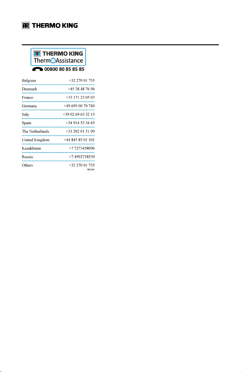
Emergency Assistance
Thermo Assistance is a multi-lingual communication tool designed to put
you in direct contact with an authorized Thermo King dealer.
TThheerrmmoo AAssssiissttaannccee sshhoouulldd oonnllyy bbee ccoonnttaacctteedd ffoorr bbrreeaakkddoowwnn aanndd rreeppaaiirr
aassssiissttaannccee..
To use this system, you need the following information before you call:
(phone charges will apply)
• Contact Phone Number
• Type of TK Unit
• Thermostat Setting
• Present Load Temperature
• Probable Cause of Fault
• Warranty Details of the Unit
• Payment Details for the Repair
Leave your name and contact number and a Thermo Assistance Operator
will call you back. At this point you can give details of the service required
and the repair will be organized.
Please note that Thermo Assistance cannot guarantee payments and the
service is designed for the exclusive use of refrigerated transporters with
products manufactured by Thermo King Corporation.
TK 61651-18-OP-EN
3
Page 4
IInnttrroodduuccttiioonn
General Inquires and Unit Maintenance
For general inquiries please contact your local Thermo King dealer.
Go to www.europe.thermoking.com and select dealer locator for your local
Thermo King dealer.
Or refer to the Thermo King Service Directory for contact information.
4
TK 61651-18-OP-EN
Page 5
IInnttrroodduuccttiioonn
Customer Satisfaction Survey
Let your voice be heard!
Your feedback will help improve our manuals. The survey is accessible
through any internet-connected device with a web browser.
Scan the Quick Response (QR) code or click or type the web address http://
irco.az1.qualtrics.com/SE/?SID=SV_2octfSHoUJxsk6x to complete the
survey.
TK 61651-18-OP-EN
5
Page 6

Table of Contents
Safety Precautions. . . . . . . . . . . . . . . . . . . . . . . . . . . . . . . . . . . . . . . . . . . . 9
Danger, Warning, Caution, and Notice . . . . . . . . . . . . . . . . . . . . . . . . 9
General Safety Practices . . . . . . . . . . . . . . . . . . . . . . . . . . . . . . . . . . . 10
Automatic Start/Stop Operation. . . . . . . . . . . . . . . . . . . . . . . . . . . . . 11
Battery Installation and Cable Routing . . . . . . . . . . . . . . . . . . . . . . . 11
Refrigerant . . . . . . . . . . . . . . . . . . . . . . . . . . . . . . . . . . . . . . . . . . . . . . . . 13
Refrigerant Oil. . . . . . . . . . . . . . . . . . . . . . . . . . . . . . . . . . . . . . . . . . . . . 14
First Aid. . . . . . . . . . . . . . . . . . . . . . . . . . . . . . . . . . . . . . . . . . . . . . . . . . . 14
Safety Decals. . . . . . . . . . . . . . . . . . . . . . . . . . . . . . . . . . . . . . . . . . . . . . 16
Service . . . . . . . . . . . . . . . . . . . . . . . . . . . . . . . . . . . . . . . . . . . . . . . . 16
Operation . . . . . . . . . . . . . . . . . . . . . . . . . . . . . . . . . . . . . . . . . . . . . 17
High Voltage. . . . . . . . . . . . . . . . . . . . . . . . . . . . . . . . . . . . . . . . . . . 17
Condenser and Evaporator Fans. . . . . . . . . . . . . . . . . . . . . . . . . 18
Remote Start of the Unit . . . . . . . . . . . . . . . . . . . . . . . . . . . . . . . . 18
Refrigerant . . . . . . . . . . . . . . . . . . . . . . . . . . . . . . . . . . . . . . . . . . . . 19
Type Certification . . . . . . . . . . . . . . . . . . . . . . . . . . . . . . . . . . . . . . 20
Unit Description . . . . . . . . . . . . . . . . . . . . . . . . . . . . . . . . . . . . . . . . . . . . . 21
Standard Unit Features. . . . . . . . . . . . . . . . . . . . . . . . . . . . . . . . . . . . . 22
Options . . . . . . . . . . . . . . . . . . . . . . . . . . . . . . . . . . . . . . . . . . . . . . . . . . . 22
System Components. . . . . . . . . . . . . . . . . . . . . . . . . . . . . . . . . . . . . . . 22
Compressor(s) . . . . . . . . . . . . . . . . . . . . . . . . . . . . . . . . . . . . . . . . . 22
Condenser. . . . . . . . . . . . . . . . . . . . . . . . . . . . . . . . . . . . . . . . . . . . . 23
Evaporator . . . . . . . . . . . . . . . . . . . . . . . . . . . . . . . . . . . . . . . . . . . . 23
Electronic Control System . . . . . . . . . . . . . . . . . . . . . . . . . . . . . . 24
Description . . . . . . . . . . . . . . . . . . . . . . . . . . . . . . . . . . . . . . . . . . . . 24
Unit Controls . . . . . . . . . . . . . . . . . . . . . . . . . . . . . . . . . . . . . . . . . . 26
Standby Operation (Models 20 and 50 Only) . . . . . . . . . . . . . . . . . 27
Electrical System . . . . . . . . . . . . . . . . . . . . . . . . . . . . . . . . . . . . . . . . . . 28
6
TK 61651-18-OP-EN
Page 7

TTaabbllee ooff CCoonntteennttss
Fuses . . . . . . . . . . . . . . . . . . . . . . . . . . . . . . . . . . . . . . . . . . . . . . . . . 28
Pharma . . . . . . . . . . . . . . . . . . . . . . . . . . . . . . . . . . . . . . . . . . . . . . . . . . . 29
Operating Instructions . . . . . . . . . . . . . . . . . . . . . . . . . . . . . . . . . . . . . . . 30
General Operation . . . . . . . . . . . . . . . . . . . . . . . . . . . . . . . . . . . . . . . . . 30
Starting the Unit . . . . . . . . . . . . . . . . . . . . . . . . . . . . . . . . . . . . . . . . . . . 31
Engine Operation . . . . . . . . . . . . . . . . . . . . . . . . . . . . . . . . . . . . . . 31
Electric Standby Operation. . . . . . . . . . . . . . . . . . . . . . . . . . . . . . 31
Standard Display . . . . . . . . . . . . . . . . . . . . . . . . . . . . . . . . . . . . . . . . . . 32
Single Temperature Units. . . . . . . . . . . . . . . . . . . . . . . . . . . . . . . 32
Multi-Temperature Units . . . . . . . . . . . . . . . . . . . . . . . . . . . . . . . 32
Entering Setpoint Temperature . . . . . . . . . . . . . . . . . . . . . . . . . . . . . 33
Single Temperature Units. . . . . . . . . . . . . . . . . . . . . . . . . . . . . . . 33
Multi-Temperature Units . . . . . . . . . . . . . . . . . . . . . . . . . . . . . . . 33
Compartment Selection . . . . . . . . . . . . . . . . . . . . . . . . . . . . . . . . 35
Initiating the Evaporator Manual Defrost Cycle . . . . . . . . . . . . . . . 37
Initiating the Condenser Manual Defrost Cycle (reverse cycle
units only) . . . . . . . . . . . . . . . . . . . . . . . . . . . . . . . . . . . . . . . . . . . . . . . . 38
Alarms. . . . . . . . . . . . . . . . . . . . . . . . . . . . . . . . . . . . . . . . . . . . . . . . . . . . 40
Manual Start. . . . . . . . . . . . . . . . . . . . . . . . . . . . . . . . . . . . . . . . . . . 40
Auto Start . . . . . . . . . . . . . . . . . . . . . . . . . . . . . . . . . . . . . . . . . . . . . 40
Buzzers. . . . . . . . . . . . . . . . . . . . . . . . . . . . . . . . . . . . . . . . . . . . . . . . 41
Alarm Code Descriptions DSR . . . . . . . . . . . . . . . . . . . . . . . . . . . . . . 42
Clearing Alarm Codes . . . . . . . . . . . . . . . . . . . . . . . . . . . . . . . . . . . . . . 43
Viewing Information Screens . . . . . . . . . . . . . . . . . . . . . . . . . . . . . . . 43
Main Menu . . . . . . . . . . . . . . . . . . . . . . . . . . . . . . . . . . . . . . . . . . . . 43
Hourmeter Menu. . . . . . . . . . . . . . . . . . . . . . . . . . . . . . . . . . . . . . . 43
Loading and Inspection Procedures . . . . . . . . . . . . . . . . . . . . . . . . . 44
TK 61651-18-OP-EN
7
Page 8

TTaabbllee ooff CCoonntteennttss
Post-Start Inspection . . . . . . . . . . . . . . . . . . . . . . . . . . . . . . . . . . . . . . . 44
Loading Procedure. . . . . . . . . . . . . . . . . . . . . . . . . . . . . . . . . . . . . . . . . 44
Post Load Procedure . . . . . . . . . . . . . . . . . . . . . . . . . . . . . . . . . . . . . . . 44
Specifications . . . . . . . . . . . . . . . . . . . . . . . . . . . . . . . . . . . . . . . . . . . . . . . 46
Refrigeration System . . . . . . . . . . . . . . . . . . . . . . . . . . . . . . . . . . . . . . 46
Compressor . . . . . . . . . . . . . . . . . . . . . . . . . . . . . . . . . . . . . . . . . . . 46
Electrical Control System . . . . . . . . . . . . . . . . . . . . . . . . . . . . . . . . . . . 46
Electric Motor (Model 50). . . . . . . . . . . . . . . . . . . . . . . . . . . . . . . . . . . 50
TracKing . . . . . . . . . . . . . . . . . . . . . . . . . . . . . . . . . . . . . . . . . . . . . . . . . . 50
Warranty . . . . . . . . . . . . . . . . . . . . . . . . . . . . . . . . . . . . . . . . . . . . . . . . . . . . 52
Inspection and Service Intervals . . . . . . . . . . . . . . . . . . . . . . . . . . . . . 53
Weekly Pre-Trip Checks . . . . . . . . . . . . . . . . . . . . . . . . . . . . . . . . . . . . 53
Weekly Pretrip Inspection . . . . . . . . . . . . . . . . . . . . . . . . . . . . . . . 53
Weekly Post-Trip Checks . . . . . . . . . . . . . . . . . . . . . . . . . . . . . . . . . . . 54
Inspection and Service Schedules . . . . . . . . . . . . . . . . . . . . . . . . . . . 54
Service Record. . . . . . . . . . . . . . . . . . . . . . . . . . . . . . . . . . . . . . . . . 55
Warranty Inspection . . . . . . . . . . . . . . . . . . . . . . . . . . . . . . . . . . . . 55
Preventive Maintenance . . . . . . . . . . . . . . . . . . . . . . . . . . . . . . . . 55
Serial Number Locations . . . . . . . . . . . . . . . . . . . . . . . . . . . . . . . . . . . . 56
Recover Refrigerant . . . . . . . . . . . . . . . . . . . . . . . . . . . . . . . . . . . . . . . . . 57
8
TK 61651-18-OP-EN
Page 9
Safety Precautions
Danger, Warning, Caution, and Notice
Thermo King® recommends that all service be performed by a Thermo King
dealer and to be aware of several general safety practices.
Safety advisories appear throughout this manual as required. Your personal
safety and the proper operation of this unit depend upon the strict
observance of these precautions.
Indicates an imminently hazardous situation which, if not
avoided, will result in death or serious injury.
Indicates a potentially hazardous situation which, if not avoided,
could result in death or serious injury.
Indicates a potentially hazardous situation which, if not avoided,
could result in minor or moderate injury and unsafe practices.
Indicates a situation that could result in equipment or propertydamage only accidents.
TK 61651-18-OP-EN
9
Page 10
SSaaffeettyy PPrreeccaauuttiioonnss
General Safety Practices
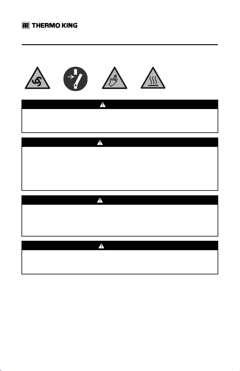
DDAANNGGEERR
RRiisskk ooff IInnjjuurryy!!
Keep hands and loose clothing clear of fans and belts at all times when the
unit is operating with the doors open.
WWAARRNNIINNGG
RRiisskk ooff IInnjjuurryy!!
Do not apply heat to a closed cooling system. Before applying heat to a
cooling system, drain it. Then flush it with water and drain the water.
Antifreeze contains water and ethylene glycol. The ethylene glycol is
flammable and can ignite if the antifreeze is heated enough to boil off the
water.
WWAARRNNIINNGG
RRiisskk ooff IInnjjuurryy!!
Temperatures above 120 degrees F (50 degrees C) can cause serious burns.
Use an infrared thermometer or other temperature measuring device
before touching any potentially hot surfaces.
CCAAUUTTIIOONN
SShhaarrpp EEddggeess!!
Exposed coil fins can cause lacerations. Service work on the evaporator or
condenser coils is best left to a certified Thermo King technician.
10
TK 61651-18-OP-EN
Page 11
SSaaffeettyy PPrreeccaauuttiioonnss
Automatic Start/Stop Operation
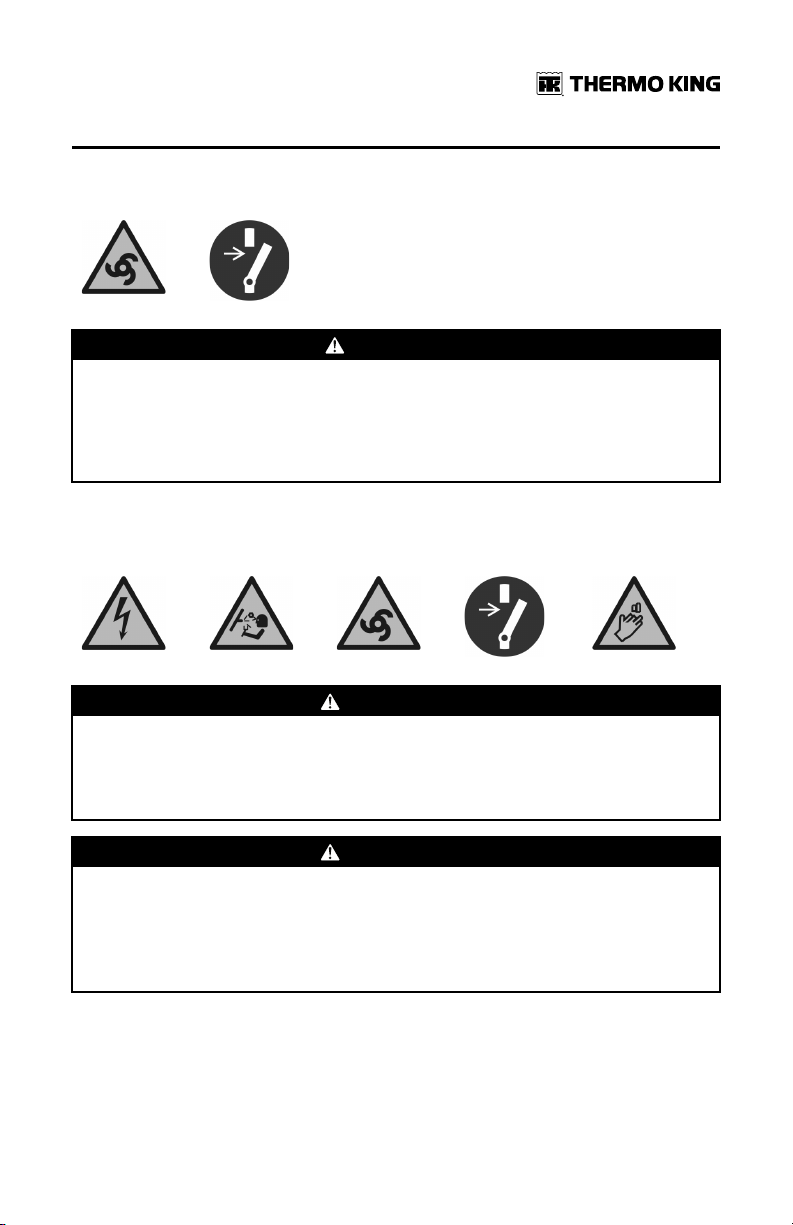
CCAAUUTTIIOONN
RRiisskk ooff IInnjjuurryy!!
The unit can start and run automatically any time the unit is turned on. Turn
the Microprocessor On/Off switch Off before doing inspections or working
on any part of the unit. Please note that only Qualified and Certified
personnel should attempt to service your Thermo King unit.
Battery Installation and Cable Routing
WWAARRNNIINNGG
HHaazzaarrdd ooff EExxpplloossiioonn!!
An improperly installed battery could result in a fire, explosion, or injury. A
Thermo King approved battery must be installed and properly secured to
the battery tray.
WWAARRNNIINNGG
HHaazzaarrdd ooff EExxpplloossiioonn!!
Improperly installed battery cables could result in a fire, explosion, or
injury. Battery cables must be installed, routed, and secured properly to
prevent them from rubbing, chaffing, or making contact with hot, sharp, or
rotating components.
TK 61651-18-OP-EN
11
Page 12
SSaaffeettyy PPrreeccaauuttiioonnss
WWAARRNNIINNGG
FFiirree HHaazzaarrdd!!
Do not attach fuel lines to battery cables or electrical harnesses. This has
the potential to cause a fire and could cause serious injury or death.
WWAARRNNIINNGG
PPeerrssoonnaall PPrrootteeccttiivvee EEqquuiippmmeenntt ((PPPPEE)) RReeqquuiirreedd!!
A battery can be dangerous. A battery contains a flammable gas that can
ignite or explode. A battery stores enough electricity to burn you if it
discharges quickly. A battery contains battery acid that can burn you.
Always wear goggles or safety glasses and personal protective equipment
when working with a battery. If you get battery acid on you, immediately
flush it with water and get medical attention.
WWAARRNNIINNGG
HHaazzaarrdd ooff EExxpplloossiioonn!!
Always cover battery terminals to prevent them from making contact with
metal components during battery installation. Battery terminals grounding
against metal could cause the battery to explode.
CCAAUUTTIIOONN
HHaazzaarrddoouuss SSeerrvviiccee PPrroocceedduurreess!!
Set all unit electrical controls to the OFF position before connecting battery
cables to the battery to prevent unit from starting unexpectedly and causing
personal injury.
NNOOTTIICCEE
EEqquuiippmmeenntt DDaammaaggee!!
Do not connect other manufacturer’s equipment or accessories to the unit
unless approved by Thermo King. Failure to do so can result in severe
damage to equipment and void the warranty.
12
TK 61651-18-OP-EN
Page 13
SSaaffeettyy PPrreeccaauuttiioonnss
Refrigerant
Although fluorocarbon refrigerants are classified as safe, use caution when
working with refrigerants or in areas where they are being used.
DDAANNGGEERR
HHaazzaarrddoouuss GGaasseess!!
Refrigerant in the presence of an open flame, spark, or electrical short
produces toxic gases that are severe respiratory irritants which can cause
serious injury or possible death.
DDAANNGGEERR
RReeffrriiggeerraanntt VVaappoorr HHaazzaarrdd!!
Do not inhale refrigerant. Use caution when working with refrigerant or a
refrigeration system in any confined area with a limited air supply.
Refrigerant displaces air and can cause oxygen depletion, resulting in
suffocation and possible death.
WWAARRNNIINNGG
PPeerrssoonnaall PPrrootteeccttiivvee EEqquuiippmmeenntt ((PPPPEE)) RReeqquuiirreedd!!
Refrigerant in a liquid state evaporates rapidly when exposed to the
atmosphere, freezing anything it contacts. Wear butyl lined gloves and
other clothing and eye wear when handling refrigerant to help prevent
frostbite.
TK 61651-18-OP-EN
13
Page 14
SSaaffeettyy PPrreeccaauuttiioonnss
Refrigerant Oil
Observe the following precautions when working with or around refrigerant
oil:
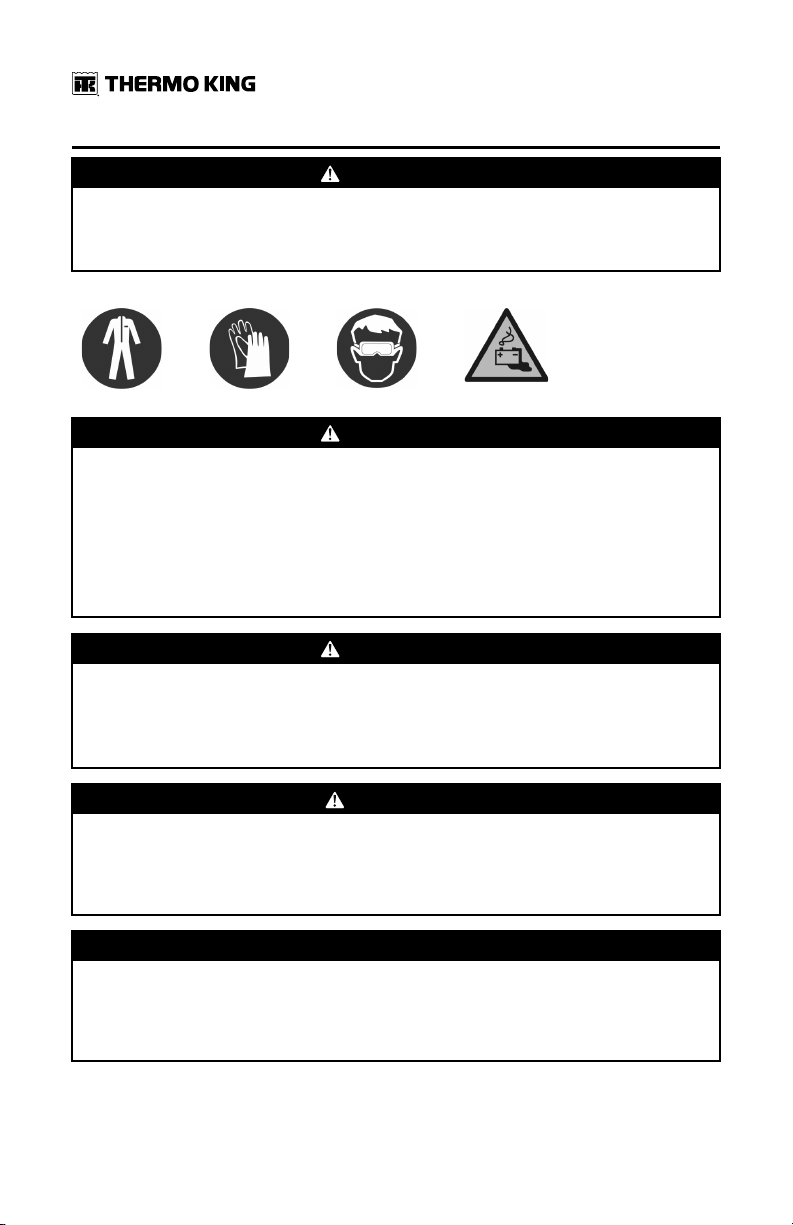
WWAARRNNIINNGG
PPeerrssoonnaall PPrrootteeccttiivvee EEqquuiippmmeenntt ((PPPPEE)) RReeqquuiirreedd!!
Protect your eyes from contact with refrigerant oil. The oil can cause serious
eye injuries. Protect skin and clothing from prolonged or repeated contact
with refrigerant oil. To prevent irritation, wash your hands and clothing
thoroughly after handling the oil. Rubber gloves are recommended.
First Aid
RREEFFRRIIGGEERRAANNTT
• EEyyeess:: For contact with liquid, immediately flush eyes with large amounts
of water and get prompt medical attention.
• SSkkiinn:: Flush area with large amounts of warm water. Do not apply heat.
Remove contaminated clothing and shoes. Wrap burns with dry, sterile,
bulky dressing to protect from infection. Get prompt medical attention.
Wash contaminated clothing before reuse.
• IInnhhaallaattiioonn:: Move victim to fresh air and use Cardio Pulmonary
Resuscitation (CPR) or mouth-to-mouth resuscitation to restore
breathing, if necessary. Stay with victim until emergency personnel
arrive.
• FFrroosstt BBiittee:: In the event of frost bite , the objectives of First Aid are to
protect the frozen area from further injury, warm the affected area
rapidly, and to maintain respiration.
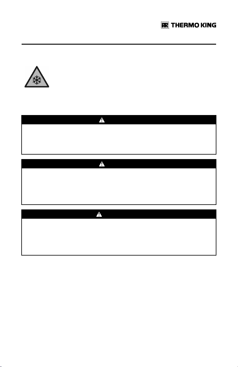
RREEFFRRIIGGEERRAANNTT OOIILL
• EEyyeess:: Immediately flush with large amounts of water for at least 15
minutes. Get prompt medical attention.
• SSkkiinn:: Remove contaminated clothing. Wash thoroughly with soap and
water. Get medical attention if irritation persists.
14
TK 61651-18-OP-EN
Page 15

SSaaffeettyy PPrreeccaauuttiioonnss
• IInnhhaallaattiioonn:: Move victim to fresh air and use Cardio Pulmonary
Resuscitation (CPR) or mouth-to-mouth resuscitation to restore
breathing, if necessary. Stay with victim until emergency personnel
arrive.
• IInnggeessttiioonn:: Do not induce vomiting. Immediately contact local poison
control center or physician.
EENNGGIINNEE CCOOOOLLAANNTT
• EEyyeess:: Immediately flush with large amounts of water for at least 15
minutes. Get prompt medical attention.
• SSkkiinn:: Remove contaminated clothing. Wash thoroughly with soap and
water. Get medical attention if irritation persists.
• IInnggeessttiioonn:: Do not induce vomiting. Immediately contact local poison
control center or physician.
BBAATTTTEERRYY AACCIIDD
• EEyyeess:: Immediately flush with large amounts of water for at least 15
minutes. Get prompt medical attention. Wash skin with soap and water.
EELLEECCTTRRIICCAALL SSHHOOCCKK
Take IMMEDIATE action after a person has received an electrical shock. Get
quick medical assistance, if possible.
The source of the shock must be quickly stopped, by either shutting off the
power or removing the victim. If the power cannot be shut off, the wire
should be cut with an non-conductive tool, such as a wood-handle axe or
thickly insulated cable cutters. Rescuers should wear insulated gloves and
safety glasses, and avoid looking at wires being cut. The ensuing flash can
cause burns and blindness.
If the victim must be removed from a live circuit, pull the victim away with a
non-conductive material. Use wood, rope, a belt or coat to pull or push the
victim away from the current. DO NOT TOUCH the victim. You will receive a
shock from current flowing through the victim’s body. After separating the
victim from power source, immediately check for signs of a pulse and
respiration. If no pulse is present, start Cardio Pulmonary Resuscitation
(CPR). If a pulse is present, respiration might be restored by using mouth-tomouth resuscitation. Call for emergency medical assistance.
AASSPPHHYYXXIIAATTIIOONN
Move victim to fresh air and use Cardio Pulmonary Resuscitation (CPR) or
mouth-to-mouth resuscitation to restore breathing, if necessary. Stay with
victim until emergency personnel arrive.
TK 61651-18-OP-EN
15
Page 16
SSaaffeettyy PPrreeccaauuttiioonnss
Safety Decals
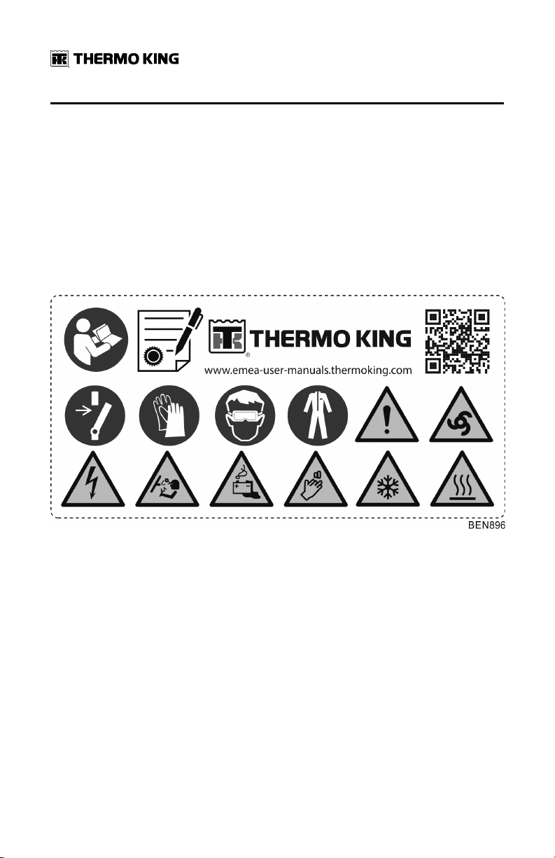
Service
The Service decal is located in an appropriate location internally. This decal
gives you the information to access/download your unit operator manual,
but also the safety icons associated with your unit. These safety icons are
directly associated with the information within this chapter. You can see the
explanations for these icons starting from the beginning of this chapter.
NNoottee:: This decal only contains symbols of warning for the service of the unit.
Figure 1. Service Decal
16
TK 61651-18-OP-EN
Page 17
SSaaffeettyy PPrreeccaauuttiioonnss
Operation
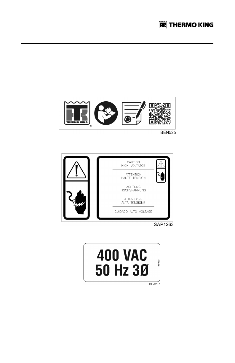
The Operation decal is located in an appropriate position near your in-cab
controller (HMI). This decal gives you the information to access/download
your unit operator manual and other supporting documentation and in many
supported languages.
Figure 2. Operation Decal
High Voltage
• In the control box.
TK 61651-18-OP-EN
17
Page 18
SSaaffeettyy PPrreeccaauuttiioonnss
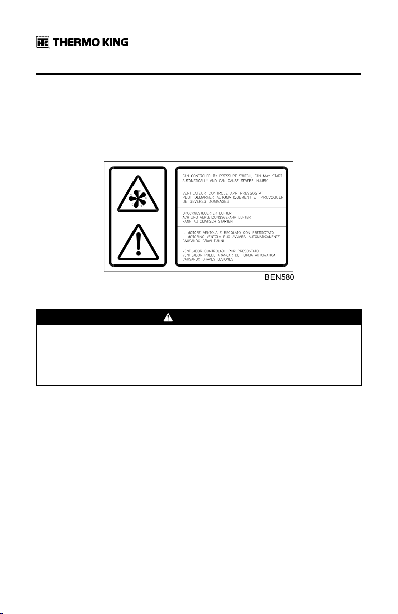
Condenser and Evaporator Fans
Be aware of the warning nameplates () in the following locations:
• On belt guard
• On rear of evaporator housing
Figure 3. Fan Warning
Remote Start of the Unit
CCAAUUTTIIOONN
RRiisskk ooff IInnjjuurryy!!
The unit can start and run automatically any time the unit is turned on. Turn
the Microprocessor On/Off switch Off before doing inspections or working
on any part of the unit. Please note that only Qualified and Certified
personnel should attempt to service your Thermo King unit.
Decals located behind service door.
18
TK 61651-18-OP-EN
Page 19

SSaaffeettyy PPrreeccaauuttiioonnss
Figure 4. Unit Auto-start Warning
Refrigerant
Refrigerant Decal is located adjacent to the service ports for charging or
recovering the gas, as per the F-Gas regulation.
F Gas decal indicates that this equipment Contains fluorinated greenhouse
gases.
TK 61651-18-OP-EN
19
Page 20

SSaaffeettyy PPrreeccaauuttiioonnss
Type Certification
UNECE R10 decal sample.
20
TK 61651-18-OP-EN
Page 21

Unit Description
Thermo King Vehicle Powered Truck Units are two-piece units comprised of
a condenser and evaporator designed for fresh, frozen, and deep frozen
applications on small trucks and vans.
A belt driven compressor running off the vehicle’s engine operates the
refrigeration system during mobile operation. Electric Standby models have
a second compressor located inside the condenser. This compressor is belt
driven off an electric motor when connected to an AC power source during
stationary operation.
The user friendly Direct Smart Reefer (DSR) controller makes operating your
unit simple, while its modular design allows for ease of service.
V-Series Units Include:
• VV--110000,, VV--220000,, VV--330000,, VV--550000,, VV--660000,, VV--880000:: for fresh temperature
applications above 0°C.
• VV--110000,, VV--220000,, VV--330000,, VV--550000,, VV--660000,, VV--880000 MMAAXX:: for frozen temperature
applications below 0°C and down to -32°C.
There are four basic models:
• MMooddeell 1100:: Cool and Defrost with only vehicle powered engine driven
compressor operation.
• MMooddeell 2200:: Cool and Defrost with both vehicle powered engine driven
compressor operation and electric standby compressor operation.
• MMooddeell 3300:: Hot gas heat, Cool, and Defrost with only vehicle powered
engine driven compressor operation.
• MMooddeell 5500:: Hot gas heat, Cool, and Defrost on both vehicle powered
engine driven operation and electric standby compressor operation.
Two add-on heat options are available:
• Coolant Heat (Models 10 and 20 only).
• Coolant and Electric Heat (Model 20 only).
TK 61651-18-OP-EN
21
Page 22

UUnniitt DDeessccrriippttiioonn
Standard Unit Features
• CCoonnddeennsseerr - Lightweight design of aluminium construction, easy to
service with automotive grade polypropylene cover.
• EEvvaappoorraattoorr - Ultra slim design, aluminum construction automotive
grade polypropylene cover.
• CCoonnttrroollss - User friendly Direct Smart Reefer (DSR) In-Cab controller.
• RReeffrriiggeerraanntt - R-134a, R-452A or R-404a (depending on unit model).
Options
• Electric Standby
• Hot Gas, Electric or Coolant Heating
• Door Switch Kit
• Discharge Muffler Kit
• Snow Covers
• Refrigeration Hose / Harness Covers
• Roof Top Mounting Kit
• Electric Standby Plug (115 Vac, 230 Vac 1 phase, 230 Vac 3 phase)
NNoottee:: Some options are available factory installed or as a retro-fit option to
suit individual customer needs.
System Components
The system consists of four main components: compressor, condenser,
evaporator, and In-cab control panel (HMI).
Compressor(s)
All vehicle-powered systems utilize an engine driven compressor, either a
swash plate or reciprocating depending on your particular model. Electric
standby models also have an electric motor that operates a second
compressor located inside the condenser.
22
TK 61651-18-OP-EN
Page 23

UUnniitt DDeessccrriippttiioonn
Figure 5. Compressors
1. Swash Plate
2. Reciprocating
Condenser
The condenser is located on the roof of the vehicle or on the front of the
cargo box. The cover can easily be removed to access the fuses or service
the unit.
Figure 6. Condenser
Evaporator
The evaporator is mounted on the ceiling inside the cargo box. The cover
can easily be removed for service.
Figure 7. Evaporator
TK 61651-18-OP-EN
23
Page 24

UUnniitt DDeessccrriippttiioonn
Electronic Control System
The Electronic Control System is composed of an Electronic Control Module
(located inside the condenser unit) and the HMI. This HMI allows the truck
driver to operate the Thermo King refrigeration unit.
Figure 8. HMI
Description
The Electronic Control System has the following characteristics:
• Auto Start
• Soft Start
• Active Display
• Lit Keypad
• Total Hourmeter
• Vehicle Compressor Hourmeter
• Electric Standby Compressor Hourmeter
• Low Battery Voltage Alarm
• Buzzer
• Unit Control without HMI
• Manual or Automatic Defrost
• Maintenance Warning
• Return Air Temperature Sensor
• Setpoint Temperature Reading
• Electric Power Warning
• Independent connection/disconnection of compartments in multitemperature units
24
TK 61651-18-OP-EN
Page 25

UUnniitt DDeessccrriippttiioonn
AAuuttoo SSttaarrtt:: Should the unit stop due to a failure in the power supply,
whether during on-the-road or electric standby operation, it will start up
again as soon as the power supply is re-established.
SSoofftt SSttaarrtt:: All operation modes remain inactive for a few seconds after an
Auto Start.
AAccttiivvee DDiissppllaayy:: The HMI display is always active and backlit except when
the unit is disconnected (no power) or when the unit is connected but has
been manually switched off from the HMI (when there is no active alarm).
LLiitt KKeeyyppaadd:: The HMI keys are always lit except when the unit is
disconnected (no power) or when the unit is connected but has been
manually switched off from the HMI (when there is no active alarm). The On/
Off key is always lit except when the unit is disconnected (no power), and
thus indicates the presence of power in the unit.
TToottaall HHoouurrmmeetteerr:: Total number of hours the unit is in operation.
VVeehhiiccllee CCoommpprreessssoorr HHoouurrmmeetteerr:: Number of hours the unit has been
operating on-the-road.
EElleeccttrriicc SSttaannddbbyy CCoommpprreessssoorr HHoouurrmmeetteerr:: Number of hours the unit has
been operating in electric standby.
LLooww BBaatttteerryy VVoollttaaggee AAllaarrmm:: Disconnects the unit when the battery voltage
falls below 10.5V in 12VDC systems or below 21V in 24VDC systems.
BBuuzzzzeerr:: It is energised when the vehicle battery and the electric power
supply are connected at the same time. It is also energised if the doors are
opened while the refrigeration unit is running.
UUnniitt CCoonnttrrooll wwiitthhoouutt HHMMII:: The unit can also be operated by the Electronic
Control System without the HMI, under conditions selected by the HMI
before it is disconnected.
MMaannuuaall oorr AAuuttoommaattiicc DDeeffrroosstt:: It is possible to choose between manual or
automatic defrost.
MMaaiinntteennaannccee WWaarrnniinngg:: On-screen warning of the need to carry out
maintenance on the unit.
RReettuurrnn AAiirr TTeemmppeerraattuurree SSeennssoorr:: On-screen reading of the temperature in
the load compartment. In bi-temperature units, the temperature in both
compartments can be read on the same screen.
SSeettppooiinntt TTeemmppeerraattuurree RReeaaddiinngg:: On-Screen Setpoint Temperature
Reading. In bi-temperature units, the setpoint temperature of both
compartments can be read on the same screen.
EElleeccttrriicc PPoowweerr WWaarrnniinngg:: On-screen warning that the unit is connected to an
electric power supply.
TK 61651-18-OP-EN
25
Page 26

UUnniitt DDeessccrriippttiioonn
Unit Controls
WWAARRNNIINNGG
RRiisskk ooff IInnjjuurryy!!
Never operate the unit unless you completely understand the controls;
otherwise serious injury may occur.
Figure 9. In-cab Control Panel (HMI) Display, Keys, Symbols
1. Display It is always active and backlit except when the unit is disconnected
2. On/Off Key This key is used to start/stop the unit. It is always lit except when the
3. Select Key Selects prompt screens and information screens.
4. Up Key Is used to increase the setpoint temperature.
5. Down Key Is used to reduce the setpoint temperature.
6. Enter Key
7. Buzzer It is energised when the vehicle battery and the electric power supply
8. Cool Symbol (Thermometer with an arrow pointing downward). The unit is cooling.
9. Heat Symbol (Thermometer with an arrow pointing upward). The unit is heating.
10. °C/°F Symbol Indicates whether the on-screen temperature reading is in degrees
11. Alarm Symbol Indicates that there is an alarm in the system.
26
(no power) or when the unit is connected but has been manually
switched off from the HMI. It normally displays the return air
temperature (of both load compartments in bi-temperature units).
unit is disconnected (no power), and thus acts as an indicator of the
presence of power in the unit.
Is used to enter a new command such as manual defrost, etc.
are connected simultaneously. It is also energized if the doors are
opened while the refrigeration unit is running.
Celsius (C) or degrees Fahrenheit (F).
TK 61651-18-OP-EN
Page 27

UUnniitt DDeessccrriippttiioonn
12. Maintenance
Symbol
13. Defrost
Symbol
14. Electrical
Symbol
15. Condenser
Defrost Symbol
16. Combined
Compartment
Symbol
Warns of the need to carry out maintenance to the unit.
Indicates the unit is in Defrost Mode.
Indicates that the unit is in Electric Standby.
Indicates the condenser unit is in defrost mode (turns on at the same
time as defrost symbol 13).
Indicates that the bi-temperature unit is working as a single
temperature unit.
Standby Operation (Models 20 and 50 Only)
WWAARRNNIINNGG
HHaazzaarrddoouuss VVoollttaaggee!!
A certified electrician should verify that the proper standby power
requirements are being supplied before connecting to a new power source.
These units may be operated in electric standby mode by connecting the
proper voltage power cable to the unit’s power receptacle mounted on the
vehicle. Standby operation is used while the vehicle is stationary with the
engine shut off.
Figure 10. Standby Power Receptacle
TK 61651-18-OP-EN
27
Page 28

UUnniitt DDeessccrriippttiioonn
Electrical System
The unit’s controls and refrigeration components operate on 12 Vdc.
Electric Standby units have a standby motor that operates on 115 or 230 Vac
when connected to a remote power source. A transformer in the condenser
unit converts the 115 or 230 Vac to 12 Vdc to operate the unit’s controls and
refrigeration components.
Fuses
The electrical components are protected by various fuses.
MMaaiinn PPoowweerr FFuussee - The main power fuse is located in the vehicle’s engine
compartment and is connected directly to the vehicle’s battery.
This 60 amp in-line fuse is non-serviceable and must only be replaced by an
authorized Thermo King Dealer.
IIggnniittiioonn PPoowweerr FFuussee - The ignition power fuse is connected to the vehicle’s
fused ignition system. Depending on the vehicle, the location of the fuse
panel could be located inside the cab or under the hood of the vehicle.
UUnniitt CCoommppoonneenntt FFuusseess - These fuses are located in the condenser unit.
Remove the condenser cover to access them. Depending on your model,
some fuses may not be used. Refer to ()Refer to (“Electrical Control
System,” p. 46).
Figure 11. Fuse Location (condenser cover removed)
28
TK 61651-18-OP-EN
Page 29

UUnniitt DDeessccrriippttiioonn
Pharma
Single and Multi-temperatures temperature Units qualified for
pharmaceutical applications under Thermo King protocol are configured
with specific Pharma configuration file and parameters loaded during
commissioning by your local dealer. Evaporators fans have to run during the
Null Cycle.
ThermoKing recommends to run the unit with the recommended Setpoints
below:
Table 1. Single Temperature units:
Temperature Range
Temperature between +15°
C and +25°C
Temperature between 15°C
and 25°C
Table 2. Multi-Temperature units:
Temperature Range
Temperature between +15°
C and +25°C
Temperature between 15°C
and 25°C
Recommended
Setpoint
+20°C
+5°C +/- 2°C of setpoint
Recommended
Setpoint
+20°C
+6°C +/- 2°C of setpoint
Max Deviation Setpoint
+1/- 2°C of setpoint
Max Deviation Setpoint
+/- 2°C of setpoint
Efficient loading practices and operating procedures have to be followed to
ensure optimum air circulation and temperature management.
TK 61651-18-OP-EN
29
Page 30

Operating Instructions
General Operation
In truck-driven units, temperature control is based on two values: The setting
(Setpoint) of the electronic thermostat and the evaporator return
temperature. The difference between these two temperatures will determine
the mode of operation: cool, heat, or null.
• CCooooll:: When the temperature in the load compartment is higher than the
setpoint, the unit runs in cool mode to reduce the evaporator return
temperature.
• HHeeaatt:: When the temperature in the load compartment is lower than the
setpoint, the unit changes to heat mode to raise the evaporator return
temperature.
• NNuullll:: Once the Setpoint Temperature has been reached, and while the
temperature remains between XºC/F above or below the setpoint, there is
no demand for transfer of heat or cold, and the unit runs in null mode.
• DDeeffrroosstt:: After a scheduled period of time in cool mode, between 1 and 8
hours, the unit runs in this fourth mode of operation to eliminate ice that
has accumulated in the evaporator or condenser coil. Defrost can be
initiated automatically or manually.
Factory setting for X is 3ºC (5ºF). During unit installation, this value can be
adjusted by between 1 and 5ºC (2 and 9ºF) in increments of 1ºC/F.
UUnniittss wwiitthh RR--113344aa rreeffrriiggeerraanntt:: Temperatures can be controlled from -20ºC
to +22ºC (-4ºF to +71ºF).
30
TK 61651-18-OP-EN
Page 31

OOppeerraattiinngg IInnssttrruuccttiioonnss
UUnniittss wwiitthh RR--440044AA //RR--445522AA rreeffrriiggeerraanntt:: Temperatures can be controlled
from -32ºC to +22ºC (-26ºF to +71ºF).
Address:
Sant Josep, 140-142 P.I. “El Pla”,
Sant Feliu de Llobregat,
Barcelona, Spain.
YYeeaarr ooff mmaannuuffaaccttuurree:: Reference Serial Plate.
Installation and commissioning are to be carried out by an authorised
Thermo King Dealer in accordance with Thermo King procedures and
drawings. Exceptions to this with the written authorisation of the
manufacturer only.
Starting the Unit
Engine Operation
1. Start the vehicle.
2. Press the On/Off Key located in the HMI. The HMI display will be
activated.
3. Check the setpoint, and adjust if necessary.
Electric Standby Operation
1. Connect the external power supply to the electric power receptacle.
Verify the power supply is of the correct voltage and phase for the unit.
WWAARRNNIINNGG
HHaazzaarrddoouuss VVoollttaaggee!!
In case of outdoor conditions, ensure that the connection is made under
safe conditions.
2. Press the On/Off Key located in the HMI. The HMI display will be
activated. The electric symbol will appear on the screen.
3. Check the setpoint, and adjust if necessary.
TK 61651-18-OP-EN
31
Page 32

OOppeerraattiinngg IInnssttrruuccttiioonnss
NNootteess::
1. Regular monitoring of the unit is recommended, the frequency of
this monitoring will depend on the type of cargo.
2. The operating mode, whether engine-driven or electric standby, is
selected automatically. When the unit is connected to an electric
power source, engine-driven operation is automatically blocked.
If the truck engine is started up while the power cable is still
connected to the electrical power source, the unit will continue to
operate in electric standby mode and the buzzer will be activated.
Standard Display
This is the display that appears when the On/Off key is pressed and the unit
started. It normally displays the return air temperature (of both load
compartments in bi-temperature units) and the current operating mode with
the appropriate symbol.
Should there be an alarm, the alarm symbol will also appear on screen.
Single Temperature Units
The example below shows 10.8ºC temperature, cool mode, and standby
operation.
Multi-Temperature Units
The example below shows -10ºC temperature and cool mode in the main
compartment, and 2ºC temperature and heat mode in the remote
compartment. Unit running in on-the-road mode.
32
TK 61651-18-OP-EN
Page 33

OOppeerraattiinngg IInnssttrruuccttiioonnss
Entering Setpoint Temperature
The Setpoint Temperature can be quickly and easily changed.
Single Temperature Units
1. Press and release the Select key twice (three times for reverse cycle
units), and the current Setpoint Temperature and the letters SP will
appear on screen.
2. Press the Up or Down arrow keys to select the desired Setpoint
Temperature. Each time either of these buttons is pressed and released,
the Setpoint Temperature will change one degree.
3. Press and release the Enter key to set the setpoint or press and release
the Select key to set the setpoint and return to the Standard Display.
IImmppoorrttaanntt:: If the Select key or the Enter key is not pressed within 20
seconds to select the new Setpoint Temperature, the unit will
continue to run at the original Setpoint Temperature.
Multi-Temperature Units
NNoottee:: Since software MSK 544.03, Thermo King has introduced a Zone
Priority function which allows Spectrum units to provide cooling or
heating priority for a specific zone to satisfy setpoint as soon as
possible. Contact your local dealer for detailed information.
TK 61651-18-OP-EN
33
Page 34

OOppeerraattiinngg IInnssttrruuccttiioonnss
1. MMaaiinn LLooaadd CCoommppaarrttmmeenntt:: Press and release the SELECT key twice, and
the current Setpoint Temperature in the main compartment and the
letters SP will appear on screen.
2. Press the UP or DOWN arrow keys to select the desired Setpoint
Temperature. Each time either of these buttons is pressed and released,
the Setpoint Temperature will change one degree.
3. Press and release the ENTER key to set the setpoint or press and release
the SELECT key to set the setpoint and to change to the RReemmoottee
CCoommppaarrttmmeenntt Setpoint Temperature Setting Screen.
IImmppoorrttaanntt:: If the Select key or the Enter key is not pressed within 20
seconds to select the new Setpoint Temperature, the unit will
continue to run at the original Setpoint Temperature.
4. RReemmoottee LLooaadd CCoommppaarrttmmeenntt:: The present Setpoint Temperature in the
remote compartment and the letters SP2 will appear on screen.
5. Press the UP or DOWN arrow keys to select the desired Setpoint
Temperature. Each time either of these buttons is pressed and released,
the Setpoint Temperature will change one degree.
6. Press and release the Enter key to set the set point value or press and
release the SELECTION key to set the set point and move to the CCSSEE
((CCoommppaarrttmmeenntt SSeelleeccttiioonn)) screen.
IImmppoorrttaanntt:: If the Select key or the Enter key is not pressed within 20
seconds to select the new Setpoint Temperature, the unit will
continue to run at the original Setpoint Temperature.
34
TK 61651-18-OP-EN
Page 35

OOppeerraattiinngg IInnssttrruuccttiioonnss
Compartment Selection
1. Press the key UP or DOWN to change option between the four different
options available:
• 11--22:: This is the standard multi-temperature setting where both
compartments (zones) are active.
– The screen shows the temperature in both compartments (zones).
• CC11:: Compartment 1 is active while Compartment 2 is disabled.
– Only the temperature for compartment 1 appears on the screen,
while no reading is shown for compartment 2.
TK 61651-18-OP-EN
35
Page 36

OOppeerraattiinngg IInnssttrruuccttiioonnss
• CC22:: Compartment 2 is active while Compartment 1 is disabled.
– Only the temperature for compartment 2 appears on the screen,
while no reading is shown for compartment 1.
• 11--11:: Compartments 1 and 2 are combined to operate as a single-
temperature unit; only the temperature for Compartment 1 is
displayed.
36
TK 61651-18-OP-EN
Page 37

OOppeerraattiinngg IInnssttrruuccttiioonnss
– The screen shown as that of a single-temperature unit but with
the triangle symbol activated to indicate that it is actually a bitemperature unit operating as a single-temperature unit.
2. Press and release the ENTER key to select an option or press and release
the SELECTION key to select an option and return to the standard screen.
IImmppoorrttaanntt:: If the Select key or the Enter key is not pressed within 20
seconds to select the new Setpoint Temperature, the unit will
continue to run at the original Setpoint Temperature.
Initiating the Evaporator Manual Defrost Cycle
IImmppoorrttaanntt:: Before initiating a manual defrost, ensure that the unit is not
already in a defrost cycle. When the unit is in a defrost cycle the
defrost symbol appears on screen.
1. Press and release the Select key once, and the letters dEF will appear
(flashing) on screen along with the present defrost condition OFF.
2. To activate manual defrost, press the Enter key and then the Up or Down
key and the defrost condition will change to On.
TK 61651-18-OP-EN
37
Page 38

OOppeerraattiinngg IInnssttrruuccttiioonnss
3. Press the Select key twice to return to the Standard Display (three times
in bi-temperature units and in reverse cycle units), where the letters dEF
and the DEFROST symbol will appear when the defrost cycle starts (the
load compartment temperature must be lower than 0ºC).
NNoottee:: The letters dEF will remain on screen for a while after returning to cool
mode.
Initiating the Condenser Manual Defrost Cycle (reverse cycle units only)
IImmppoorrttaanntt:: Before initiating a manual defrost, ensure that the unit is not
already in a defrost cycle. When the unit is in a defrost cycle the
defrost symbol appears on screen.
1. Press and release the Select key twice, and the letters dFC will appear
(flashing) on screen along with the present defrost condition OFF.
38
TK 61651-18-OP-EN
Page 39

OOppeerraattiinngg IInnssttrruuccttiioonnss
2. To activate manual defrost, press the Enter key and then the Up or Down
key and the defrost condition will change to On.
3. Press the Select key twice to return to the Standard Display where the
letters dFC and the DEFROST symbol will appear when the defrost cycle
starts (the outside ambient temperature must be lower than 0ºC).
TK 61651-18-OP-EN
39
Page 40

OOppeerraattiinngg IInnssttrruuccttiioonnss
Alarms
When the unit is not operating properly, the microprocessor records the
alarm code, alerts the operator by displaying the Alarm symbol and,
depending on the type of alarm, shuts the unit down.
TThheerree aarree tthhrreeee aallaarrmm ccaatteeggoorriieess::
Manual Start
The alarm stops the unit, and only the Alarm symbol appears on screen.
Once the alarm condition has been rectified, the On/Off key must be pressed
to start up again.
Press and release the Select key to display the current alarm code on screen.
If there is more than one active alarm, all the alarm codes on the unit can be
viewed in sequence by pressing and releasing the Select key.
Auto Start
The alarm stops the unit, the Alarm symbol appears on screen and the unit
starts up automatically once the alarm condition has been rectified.
Should a PP11EE alarm occur (return air temperature read error alarm code)
appear, — will appear on screen together with the alarm symbol, instead of
the return air temperature reading.
40
TK 61651-18-OP-EN
Page 41

OOppeerraattiinngg IInnssttrruuccttiioonnss
If it is a multi-temperature unit, the — will appear on the screen together with
the alarm symbol, instead of the main compartment return air temperature
reading.
In multi-temperature units, should a PP22EE - return air temperature read error
in the remote compartment alarm code - appear, — will also appear on
screen together with the alarm symbol, instead of the remote compartment
return air temperature reading.
Press and release the Select key to display the current alarm code on screen.
If there is more than one active alarm, all the alarm codes on the unit can be
viewed in sequence by pressing and releasing the Select key.
Buzzers
The buzzers are energized when the vehicle battery and the electrical supply
are connected simultaneously (the unit continues running in Standby mode).
The buzzers are also energized if the doors open, if this option is selected.
TK 61651-18-OP-EN
41
Page 42

OOppeerraattiinngg IInnssttrruuccttiioonnss
Alarm Code Descriptions DSR
Alarm Description
Manual Start
OL Electric Motor Overload (Electric standby models only) - The
bAt Low Battery Voltage - Check vehicle battery.
Auto Start
HP High Pressure Alarm - The system has detected excessively high
LP Low Pressure Alarm - The system has detected excessively low suction
PSE High Pressure Sensor Failure - The high pressure sensor has become
dr1, dr2 Cargo Doors Are Open (Units with door switch option only) - Doors
tCO Control Module Overheating
SOF Software Failure
P1E Faulty Cargo Box Return Air Temperature Sensor - Faulty or
P2E
C Communications Failure
electric motor overload relay has tripped due to excessive current draw.
If the problem persists when the unit is restarted, contact your Thermo
King Dealer.
discharge pressure.
If the problem persists when the unit is restarted, contact your Thermo
King Dealer.
pressure.
If the problem persists when the unit is restarted, contact your Thermo
King Dealer.
faulty or disconnected.
Contact your Thermo King Dealer.
are open, faulty door switches, or improper door switch configuration.
Contact your Thermo King Dealer.
If the problem persists when the unit is restarted, contact your Thermo
King Dealer.
Contact your Thermo King Dealer.
disconnected return air temperature sensor.
Contact your Thermo King Dealer.
Remote Cargo Box Return Air Temperature Reading Error (open
circuit or short-circuit)
Contact your Thermo King Dealer.
Contact your Thermo King Dealer.
42
TK 61651-18-OP-EN
Page 43

OOppeerraattiinngg IInnssttrruuccttiioonnss
Clearing Alarm Codes
The alarm condition in the unit must first be corrected. See important note
below. After resolving the alarm condition, press and release the Select key
to remove existing Alarm codes. The Standard Display will appear once the
Alarm codes have been cleared.
TToo CClleeaarr AAllaarrmm CCooddeess::
• Correct the cause of the alarm code.
• Press the Select key to remove the alarm code.
• If more than one alarm code is present, press the Select key to clear each
alarm code individually.
IImmppoorrttaanntt:: Continually clearing alarm codes without resolving the problem
will result in damage to the unit and compressor.
Viewing Information Screens
Main Menu
From the Standard Display use the Select key to display:
1. Alarms (if any active).
2. Evaporator Manual Defrost.
3. Condenser Manual Defrost (reverse cycle units only).
4. Temperature Setpoint.
Hourmeter Menu
From the Standard Display press the Select key for three seconds to open
the Hourmeter Menu, then use the Select key to display:
NNoottee:: For units with firmware version 380.03 and earlier: The unit of
measurement is tens of hours (e.g., 150 = 1500 hours). For units with
firmware version 380.06 and later: The unit of measurement is hours.
1. HHCC:: Hours remaining to maintenance notice.
2. ttHH:: The total amount of time the unit has been switched on protecting the
load.
3. CCCC:: Engine driven compressor operating hours.
4. EECC:: Electric standby compressor operating hours.
5. Return to Main Menu.
TK 61651-18-OP-EN
43
Page 44

Loading and Inspection Procedures
This chapter describes pre-loading inspections, loading procedures, postloading procedures, post-loading inspections and enroute inspections.
Thermo King refrigeration units are designed to maintain the required
product load temperature during transit. Follow these recommended loading
and enroute procedures to help minimize temperature related problems.
Post-Start Inspection
TThheerrmmoossttaatt:: Adjust the thermostat setting to above and below the
compartment temperature to check thermostat operation (see Operating
Modes).
PPrree--ccoooolliinngg:: With the thermostat set at the desired temperature, run the
unit for half-an-hour to one hour (or longer if possible) before loading the
truck. Pre-cooling eliminates residual heat and acts as a good test of the
refrigeration system.
DDeeffrroosstt:: When the unit has finished pre-cooling the truck interior - the
evaporator temperature should have dropped below 2ºC (35.6ºF) - initiate a
defrost cycle with the manual defrost switch. The defrost cycle should stop
automatically.
Loading Procedure
1. To minimise frost accumulation in the evaporator coil and a heat
increase inside the load compartment, ensure that the unit is OFF before
opening the doors (The unit may continue to run when the truck is being
loaded in a warehouse with the doors closed).
2. Carefully check and record the load temperature when loading the truck.
Note whether any products are out of temperature range.
3. Load the product in such a way that there is sufficient space for the air to
circulate throughout the load. DO NOT block the evaporator inlet or
outlet.
4. Product should be pre-cooled before loading. Thermo King units are
designed to maintain the load at the temperature at which it is loaded.
Transport refrigeration units are not designed to reduce the load
temperature.
Post Load Procedure
1. Verify all doors are closed and locked.
44
TK 61651-18-OP-EN
Page 45

LLooaaddiinngg aanndd IInnssppeeccttiioonn PPrroocceedduurreess
2. Adjust the thermostat to the desired temperature setpoint.
3. Start the unit.
4. Half an hour after loading the truck, defrost the unit for a moment by
pressing the Manual Defrost switch. If the coil temperature drops to
below 2ºC (35.6ºF), the unit will defrost. The defrost cycle should stop
automatically.
TK 61651-18-OP-EN
45
Page 46

Specifications
Refrigeration System
Contact your Thermo King dealer for refrigeration system service or
maintenance.
Compressor
V-100/
V-200s
Compressor Model QP08N QP13 QP15 QP16 QP21
Displacement (cc) 82 131 146.7 163 215
Number of cylinders
6 6 6 6 10
V-200 V-300 V-500/
V-600
V-800
Electrical Control System
12 Vdc 24 Vdc
Fuses
Common Fuses
Fuse 3: Evaporator Fan Motor (EFM1) 15 amps 10 amps
Fuse 4: Evaporator Fan Motor (EFM2) 15 amps 10 amps
Fuse 5: Roadside (Engine) Compressor Clutch
(CCL1), Liquid Injection Switch (LIS), Liquid
Injection Valve (LIV), EVAP1 Defrost Hot Gas
Solenoid Valve (PS1), Compressor Motor Contactor
(CMC), Heat Pilot Solenoid (PS5)
Fuse 14: Vehicle Ignition Switch 5 amps 5 amps
Fuse 30: Condenser Fan Motor (CFM) (located in
CF1 wire near terminal strip in condenser section)
20 amps 10 amps
16 amps 10 amps
V-100/V-200s
Fuse 6: Condenser Fan 1/2 2 amps 2 amps
Fuse 21: Battery Power Supply (located in 2 wire
near battery)
46
30 amps 30 amps
TK 61651-18-OP-EN
Page 47

SSppeecciiffiiccaattiioonnss
V-200/V-300 and Spectrum
Fuse 6: Condenser Fan 1/2 2 amps 2 amps
Fuse 8: (Spectrum Only) EVAP2 Liquid Solenoid
Valve (PS2), EVAP1 Liquid Solenoid Valve (PS3),
EVAP2 Defrost Hot Gas Solenoid Valve (PS4), Drain
Heaters 3 and 4 (HT3, HT4)
Fuse 9: (Spectrum Only) Evaporator Fan 3 15 amps 10 amps
Fuse 10: (Spectrum Only) Evaporator Fan 4 15 amps 10 amps
Fuse 11: Drain Heaters (H1 and H2) 2 amps 2 amps
Fuse 20: Transformer AC Power Supply (located at
compressor motor contactor in condenser section)
Fuse 21: Battery Power Supply (located in 2 wire
near battery)
V-500/V-600 and Spectrum
Fuse 6: Condenser Fan 1/2 10 amps 7.5 amps
Fuse 8: (Spectrum Only) EVAP2 Liquid Solenoid
Valve (PS2), EVAP1 Liquid Solenoid Valve (PS3),
EVAP2 Defrost Hot Gas Solenoid Valve (PS4), Drain
Heaters 3 and 4 (HT3, HT4)
Fuse 9: (Spectrum Only) Evaporator Fan 3 15 amps 10 amps
Fuse 10: (Spectrum Only) Evaporator Fan 4 15 amps 10 amps
Fuse 11: Drain Heaters (H1 and H2) 2 amps 2 amps
Fuse 17: Drain Heaters (H3 and H4) 2 amps 2 amps
Fuse 20: Transformer AC Power Supply (located at
compressor motor contactor in condenser section)
Fuse 21: Battery Power Supply (located in 2 wire
near battery)
Fuse 31: Condenser Fan Motor 2 (CFM2) (located in
CF2 wire near terminal strip in condenser section)
20 amps 10 amps
4 amps 4 amps
40 amps 40 amps
20 amps 10 amps
4 amps 4 amps
50 amps
(Single Temp)
16 amps 10 amps
60 amps (MultiTemp)
TK 61651-18-OP-EN
47
Page 48

SSppeecciiffiiccaattiioonnss
V-800 and Spectrum
Fuse 6: Drain Heaters 1/2 2 amps 2 amps
Fuse 8: (Spectrum Only) EVAP2 Liquid Solenoid
Valve (PS2), EVAP1 Liquid Solenoid Valve (PS3),
EVAP2 Defrost Hot Gas Solenoid Valve (PS4), Drain
Heaters 3 and 4 (HT3, HT4)
Fuse 9: (Spectrum Only) Evaporator Fan 3 15 amps 10 amps
Fuse 10: (Spectrum Only) Evaporator Fan 4 15 amps 10 amps*
Fuse 11: Drain Heaters (H3 and H4) 2 amps 2 amps
Fuse 15: TracKing 5 amps 5 amps
Fuse 16: TracKing 5 amps 5 amps
Fuse 17: TracKing 5 amps 5 amps
Fuse 20: Transformer AC Power Supply (located at
compressor motor contactor in condenser section)
Fuse 21: Battery Power Supply (located in 2 wire
near battery)
Fuse 31: Condenser Fan Motor 2 (CFM2) (located in
CF2 wire near terminal strip in condenser section)
Note: * 15 A in Spectrum Versions with Double Evaporator Fan 4
Condenser Fan Motor (All except V-800)
Voltage 13 Vdc 26 Vdc
Full Load Current 10 Amps 4.7 Amps
Power Rating 130 W 122 W
RPM with Full Load 2,800 2,800
20 amps 10 amps
2 x 2 amps 2 x 2 amps
2 x 30 amps 2 x 30 amps
16 amps 10 amps
Condenser Fan Motor (V-800)
Voltage 13 Vdc 26 Vdc
Full Load Current 11 Amps 9 Amps
Power Rating 145 W 230 W
RPM with Full Load
48
2,670 2,900
TK 61651-18-OP-EN
Page 49

SSppeecciiffiiccaattiioonnss
Evaporator Fan Motors (Each)
Voltage 13 Vdc 26 Vdc
Full Load Current 7.5 Amps 4 Amps
Power Rating 97.5 W 104 W
RPM with Full Load 2,800 2,800
Transformer
Power 500 VA
Frequency 50/60 Hz
Primary Inputs 115-208-230 Vac
Secondary Nominal Voltage 11.7 Vac (21.4 Amps)
TK 61651-18-OP-EN
49
Page 50

SSppeecciiffiiccaattiioonnss
Electric Motor (Model 50)
AC Electric Compressor Motors and Overload Relays
Voltage/
Phase/
Frequency
V-100/V-200s
230/1/50 2.0 1.5 1750 5.4 5.5
V-200/V-300
230/1/50 2.0 1.5 1750 8.6 8.6
230/1/60 2.0 1.5 1750 9 9
230/3/60 2.4 1.8 1750 6.9 6.9
400/3/50 2.4 1.8 1750 4 4
400/3/60
V-500/V-600
115/1/60 1.5 1.1 1710 14 14
208/1/60 2.0 1.5 1740 9.5 9.5
230/1/60
208/3/60 2.4 1.8 1730 7.2 7.2
230/3/60 2.4 1.8 1750 6.9 7
V-800 (ES600+2xES150)
230/3/50 2.4 1.8 1750 66.6/9.6
230/3/60 2.4 1.8 1750 19.9/11.5
Horse-
power
2.4 1.8 1750 4 4
2.0 1.5 1750 9 9
Kilowatts
RPM
Full Load
(amps)
amps
amps
Overload
Relay
Setting
(amps)
9.6
11.5
TracKing
Platform ARM Cortex-A8, 300MHz, 256MB RAM, 4GB Flash, Linux
GSM/GPRS 3G, Sierra HL8548
GPS u-blox NEO-7M
50
TK 61651-18-OP-EN
Page 51

SSppeecciiffiiccaattiioonnss
Bluetooth Version 4.0 Bluetooth Classic /Bluetooth Low Energy (BLE)
Serial Ports 2 External Serial Ports for TracKing extensions or Third-
Input Power 12V Nominal
Backup Battery Single cell Li-Ion 3.7V Nominal, > 2Ah
Environmental Storage
Temperature
Party Connect
-40 to +85 C
TK 61651-18-OP-EN
51
Page 52

Warranty
Please contact your nearest Thermo King dealer for terms of the Thermo
King North American Trailer Unit Limited Warranty.
Please also refer to TK 61654-18-WA Thermo King EMEA Unit Limited
Warranty for Vehicle Powered Truck Units.
52
TK 61651-18-OP-EN
Page 53

Inspection and Service Intervals
Weekly Pre-Trip Checks
1. Visually inspect belt.
2. Listen for unusual noises, vibrations, etc.
3. Visually inspect unit for fluid leaks (coolant, oil, refrigerant).
4. Visually inspect unit for damaged, loose or broken parts (including air
ducts and bulkheads, if so equipped).
5. In the event of excess of dirt or obstruction clean the unit, including
condenser and evaporator coils.
Weekly Pretrip Inspection
The following Weekly Pretrip Inspection should be completed before starting
the unit and loading the truck. While the weekly inspection in not a substitute
for regularly scheduled maintenance inspections, it is important part of the
preventive maintenance program designed to head off operating problems
before they happen.
LLeeaakkss:: Inspect for refrigerant leaks and worn refrigerant lines.
BBaatttteerryy:: Terminals should be properly tightened and show no signs of
corrosion.
BBeellttss:: Inspect for cracks, wear, and proper belt tension.
MMoouunnttiinngg BBoollttss:: Verify bolts are properly tightened.
EElleeccttrriiccaall:: Electrical connections should be securely fastened. Wires and
terminals should be free of corrosion, cracks, or moisture.
SSttrruuccttuurraall:: Visually check for physical damage.
CCooiillss:: The condenser and evaporator coils (evaporator coils in bitemperature units) should be clean and free of debris.
• Washing with clean water should be sufficient. The use of cleaning
agents or detergents is strongly discouraged due to the possibility of
degradation of the construction. If using a power washer, the nozzle
pressure should not exceed 600 psi (41 bar). For the best results, spray
the coil perpendicular to the face of the coil. The spray nozzle should be
kept between 1 inch and 3 inches (25 to 75 millimetres) from the coil
surface. If necessary to use a chemical cleaner or detergent use a cleaner
that does not contain any hydrofluoric acids and is between 7 and 8 on
the pH scale. Ensure dilution instructions provided by the detergent
supplier are followed. In case of doubt about the compatibility of the
TK 61651-18-OP-EN
53
Page 54

IInnssppeeccttiioonn aanndd SSeerrvviiccee IInntteerrvvaallss
detergent with the type of materials listed above, always ask the supplier
a written confirmation of the compatibility. Should a chemical cleaner be
required, it is MANDATORY that all components are thoroughly rinsed
with water even if the instructions of the cleaner specify that it is a “no
rinse” cleaner. Failure to comply with above mentioned guidelines will
lead to a shortened life of the equipment to an indeterminable degree.
The repeated transportation of meat and fish waste can cause extensive
corrosion to the evaporator coils and evaporator section tubing over time
due to ammonia formation and can reduce the lifespan of the coils.
Appropriate additional measures should be taken to protect the coils
against the aggressive corrosion that can result from transportation of
such products.
LLooaadd CCoommppaarrttmmeenntt:: Inspect the interior and exterior of the truck for any
damage. Any damage to the walls or insulation should be repaired.
DDeeffrroosstt DDrraaiinnss:: Check the defrost drain hoses and fittings to ensure they are
not blocked.
DDoooorrss:: Verify doors and weather seals are in good condition and seal
hermetically.
SSiigghhtt ggllaassss:: Check that the refrigerant charge sight glass on the running
unit is totally full (the cargo compartment temperature must be
approximately 0ºC).
Weekly Post-Trip Checks
NNOOTTIICCEE
EEqquuiippmmeenntt DDaammaaggee!!
Do not use pressurised water.
1. Clean the outside cover of the unit. Use a damp cloth and neutral
detergents. Do not use harsh cleaning products or solvents.
2. Check for leaks.
3. Check for loose or missing hardware.
4. Check for physical damage to the unit.
Inspection and Service Schedules
To ensure that your Thermo King unit operates reliably and economically
over its full life, and to avoid limiting its warranty cover, the appropriate
inspection and service schedule must be followed. Inspection and Service
intervals are determined by the number of unit operating hours and by the
54
TK 61651-18-OP-EN
Page 55

IInnssppeeccttiioonn aanndd SSeerrvviiccee IInntteerrvvaallss
age of the unit. Examples are shown in the table below. Your Dealer will
prepare a schedule to suit your specific needs.
Operating
Hours
per Year
Inspection 6 months/ 500 hours
Inspection 12 months/ 1000 hours
Inspection 18 months/ 1500 hours 12 months/ 2000 hours
Full
Service
1000 2000 3000
6 months/ 1000 hours 4 months/ 1000 hours
(+ warranty
Inspection)
8 months/ 2000 hours
(+ warranty
Inspection)
24 months/ 2000 hours 18 months/ 3000 hours 12 months/ 3000 hours
(+ warranty
Inspection)
(continue as above) (continue as above) (continue as above)
Service Record
Each inspection and service performed should be recorded on the Service
Record Sheet found at the back of this manual.
Warranty Inspection
The unit must be presented at the buyers expense at an authorised Thermo
King dealer or service provider for an inspection. The inspection will verify
that the unit has been correctly maintained and any upgrades or repairs
deemed necessary will be carried out. Subject to a satisfactory inspection,
the second twelve months warranty cover will be authorised. This is
illustrated in the table above.
Preventive Maintenance
Refer to the previous page for checks that should be carried out daily/weekly
on the unit. Please work with your Dealer in order to create a maintenance
schedule which fits your needs.
TK 61651-18-OP-EN
55
Page 56

Serial Number Locations
1. CCOONNDDEENNSSEERR:: Nameplate located on the front inside edge of condenser
frame (Cover needs to be removed).
2. SSTTAANNDDBBYY CCOOMMPPRREESSSSOORR:: 20 and 50 Models only. Nameplate located
on standby compressor body. Standby compressor is located inside the
Condenser.
3. EENNGGIINNEE DDRRIIVVEENN CCOOMMPPRREESSSSOORR:: Nameplate located on compressor
body. Engine driven compressor is located in the vehicle’s engine
compartment.
Figure 12. Condenser and Standby Compressor Serial Number Locations
Figure 13. Engine Driven Compressor Serial Number Location
56
TK 61651-18-OP-EN
Page 57

Recover Refrigerant
At Thermo King®, we recognize the need to preserve the environment and
limit the potential harm to the ozone layer that can result from allowing
refrigerant to escape into the atmosphere.
We strictly adhere to a policy that promotes the recovery and limits the loss
of refrigerant into the atmosphere.
In addition, service personnel must be aware of Federal regulations
concerning the use of refrigerants and the certification of technicians. For
additional information on regulations and technician certification programs,
contact your local THERMO KING dealer.
TK 61651-18-OP-EN
57
Page 58

NNootteess
58
TK 61651-18-OP-EN
Page 59

NNootteess
TK 61651-18-OP-EN
59
Page 60

Ingersoll Rand (NYSE: IR) advances the quality of life by creating comfortable,
sustainable and efficient environments. Our people and our family of brands —
including Club Car
®
, Ingersoll Rand®, Thermo King®and Trane®—work together
to enhance the quality and comfort of air in homes and buildings; transport and
protect food and perishables; and increase industrial productivity and efficiency.
We are a global business committed to a world of sustainable progress and
enduring results.
ingersollrand.com
Ingersoll Rand has a policy of continuous product and product data improvements and reserves the
right to change design and specifications without notice.
We are committed to using environmentally conscious print practices.
TK 61651-18-OP-EN 03 Dec 2018
Supersedes TK 51916-18-OP-EN (January 2016) ©2018 Ingersoll Rand
 Loading...