

Page 1

V250
TK 40839-1-MM (Rev. 2, 1/99)
©
Copyright
Printed in U.S.A.
1994 Thermo King Corp., Minneapolis, MN, U.S.A.
Page 2

The maintenance information in this manual covers unit models:
V250 10 (914500) Condenser 10 Plus (085067)
V250 20 Generic (085007) Condenser 10 Plus UK (085068)
V250 LOTEMP (715394) Kit - low temperature (715394)
Condenser 10 (085001) E1000 Evaporator (085031)
Evaporator - Thin Line (085003) E1000E Evaporator (085034)
V250 115/1/60 Standby (085009) V250/E1000E Evaporator (085041)
Evaporator (085005) V250 Converte (085066)
For further information, refer to…
V250 Parts Manual TK 40834
Diagnosing Thermo King Refrigeration Systems TK 5984
Tool Catalog TK 5955
V250 Operating Manual TK 40836
Installation Manual TK 41156
The information in this m anual is provided to as sist owners, operat ors and service peo ple in the proper upk eep
and maintenance of Thermo King units. For detailed descriptions of Thermo King engines, compressors, or
refrigeration systems , see the app ropria te Thermo King Over haul Man ual or Ref rigerat ion Syste ms Main tenanc e
Manual.
This manual is published for informational purposes only and the information so provided should not be considered
as all-inclusive or covering all c ont ing enc ie s. If fu rt her i nformation is required, T h er mo Ki ng C or por ation should be
consulted.
Sale of product shown in this manual is subject to Thermo King’s terms and conditions including, but not limited to,
the Thermo King Limited Express Warranty. Such terms and conditions are available upon request.
Thermo King’s warranty will not appl y to any equipm ent which has been “so r epaired or alter ed outside the manufacturer’s plants as, in the manufacturer’s judgment, to effect its stability.”
No warranties, express or implied, including warranties of fitness for a particular purpose or merchantability, or warr anties ar ising from c ourse o f dea ling or usage of trade, a re made rega rding the information , recommendations, and descriptions contained herein. Manufacturer is not responsible and will not be held
liable in contract or in tort (including negligence) for any special, indirect or consequential damages,
including injury or damage caused to vehicles, contents or persons, by reason of the installation of any
Thermo King product or its mechanical failure.
Page 3
Recover Refrigerant
At Thermo King, we recognize the need to pr eserve the
environment and limit the potential harm to the ozone
layer that can result from allowing refrigerant to escape
into the atmosphere.
We strictly adhere to a policy that promotes the recovery
and limits the loss of refrigerant into the atmosphere.
In addition, service personnel must be a ware of Federal
regulations concerning the use of refrigerants and the
certification of technicians. For additional informatio n on
regulations and technician certification programs, contact your local THERMO KING dealer.
R-404A R-134a
WARNING: Use ONLY Polyol Ester based refrigeration compressor oil (TK P/N 203-413) in
R-404A and R-134a units.
DO NOT use Polyol Ester based oil in standard Thermo King units.
DO NOT mix Polyol Ester and standard synthetic compressor oils.
Keep Polyol Ester compressor oil in tightly sealed containers. If Polyol Ester oil becomes
contaminated with moisture or standard oils, dispose of properly—DO NOT USE!
WARNING: When servicing Thermo King R-404A and R-134a units, use only those service
tools certified for and dedicated to R-404A or R-134a refrigerant and Polyol Ester
compressor oils. Residual non-HFC refrigerants or oils will contaminate R-404A and R-134a
systems.
Page 4

Table of Contents
Safety . . . . . . . . . . . . . . . . . . . . . . . . . . . . . . . . . . . . . . . . . . . . . . . . . . . . . . . . . . . . . . . . . . . . . . . . . . . . . . . . . . . . i
Specifications . . . . . . . . . . . . . . . . . . . . . . . . . . . . . . . . . . . . . . . . . . . . . . . . . . . . . . . . . . . . . . . . . . . . . . . . . . . . .1
Maintenance Inspection Schedule. . . . . . . . . . . . . . . . . . . . . . . . . . . . . . . . . . . . . . . . . . . . . . . . . . . . . . . . . . . . 5
Unit Description . . . . . . . . . . . . . . . . . . . . . . . . . . . . . . . . . . . . . . . . . . . . . . . . . . . . . . . . . . . . . . . . . . . . . . . . . . .7
Liquid Injection System . . . . . . . . . . . . . . . . . . . . . . . . . . . . . . . . . . . . . . . . . . . . . . . . . . . . . . . . . . . . . . . . . . . . 7
Oil Separator . . . . . . . . . . . . . . . . . . . . . . . . . . . . . . . . . . . . . . . . . . . . . . . . . . . . . . . . . . . . . . . . . . . . . . . . . . . .8
Unit Operation . . . . . . . . . . . . . . . . . . . . . . . . . . . . . . . . . . . . . . . . . . . . . . . . . . . . . . . . . . . . . . . . . . . . . . . . . . .8
Unit Features. . . . . . . . . . . . . . . . . . . . . . . . . . . . . . . . . . . . . . . . . . . . . . . . . . . . . . . . . . . . . . . . . . . . . . . . . . . . 9
Protection Features . . . . . . . . . . . . . . . . . . . . . . . . . . . . . . . . . . . . . . . . . . . . . . . . . . . . . . . . . . . . . . . . . . . . . .10
Optional Features . . . . . . . . . . . . . . . . . . . . . . . . . . . . . . . . . . . . . . . . . . . . . . . . . . . . . . . . . . . . . . . . . . . . . . . .10
Serial Number Locations . . . . . . . . . . . . . . . . . . . . . . . . . . . . . . . . . . . . . . . . . . . . . . . . . . . . . . . . . . . . . . . . . .10
Operating Instructions . . . . . . . . . . . . . . . . . . . . . . . . . . . . . . . . . . . . . . . . . . . . . . . . . . . . . . . . . . . . . . . . . . . . 23
Unit Controls . . . . . . . . . . . . . . . . . . . . . . . . . . . . . . . . . . . . . . . . . . . . . . . . . . . . . . . . . . . . . . . . . . . . . . . . . . . .23
Unit Protection Devices. . . . . . . . . . . . . . . . . . . . . . . . . . . . . . . . . . . . . . . . . . . . . . . . . . . . . . . . . . . . . . . . . . . 24
Unit Operation . . . . . . . . . . . . . . . . . . . . . . . . . . . . . . . . . . . . . . . . . . . . . . . . . . . . . . . . . . . . . . . . . . . . . . . . . . .25
Bi-monthly Pre-Trip Checks . . . . . . . . . . . . . . . . . . . . . . . . . . . . . . . . . . . . . . . . . . . . . . . . . . . . . . . . . . . . . . . .25
Starting the Unit. . . . . . . . . . . . . . . . . . . . . . . . . . . . . . . . . . . . . . . . . . . . . . . . . . . . . . . . . . . . . . . . . . . . . . . . . 25
Adjusting the Thermostat . . . . . . . . . . . . . . . . . . . . . . . . . . . . . . . . . . . . . . . . . . . . . . . . . . . . . . . . . . . . . . . . . .26
After Start Inspection. . . . . . . . . . . . . . . . . . . . . . . . . . . . . . . . . . . . . . . . . . . . . . . . . . . . . . . . . . . . . . . . . . . . . 26
Loading Procedure . . . . . . . . . . . . . . . . . . . . . . . . . . . . . . . . . . . . . . . . . . . . . . . . . . . . . . . . . . . . . . . . . . . . . . .26
Post Loading Procedure . . . . . . . . . . . . . . . . . . . . . . . . . . . . . . . . . . . . . . . . . . . . . . . . . . . . . . . . . . . . . . . . . . .27
Bi-monthly Post Trip Checks. . . . . . . . . . . . . . . . . . . . . . . . . . . . . . . . . . . . . . . . . . . . . . . . . . . . . . . . . . . . . . . 27
Electrical Maintenance . . . . . . . . . . . . . . . . . . . . . . . . . . . . . . . . . . . . . . . . . . . . . . . . . . . . . . . . . . . . . . . . . . . . .29
Unit Wiring. . . . . . . . . . . . . . . . . . . . . . . . . . . . . . . . . . . . . . . . . . . . . . . . . . . . . . . . . . . . . . . . . . . . . . . . . . . . . .29
Cab Control Box . . . . . . . . . . . . . . . . . . . . . . . . . . . . . . . . . . . . . . . . . . . . . . . . . . . . . . . . . . . . . . . . . . . . . . . . 29
Selecting the Temperature Scale . . . . . . . . . . . . . . . . . . . . . . . . . . . . . . . . . . . . . . . . . . . . . . . . . . . . . . . . . . . .29
Selecting the Setpoint Range . . . . . . . . . . . . . . . . . . . . . . . . . . . . . . . . . . . . . . . . . . . . . . . . . . . . . . . . . . . . . . 29
Setpoint Differential Adjustment . . . . . . . . . . . . . . . . . . . . . . . . . . . . . . . . . . . . . . . . . . . . . . . . . . . . . . . . . . . . 30
Testing the Cab Control Box . . . . . . . . . . . . . . . . . . . . . . . . . . . . . . . . . . . . . . . . . . . . . . . . . . . . . . . . . . . . . . . 31
Display Diagnosis Chart . . . . . . . . . . . . . . . . . . . . . . . . . . . . . . . . . . . . . . . . . . . . . . . . . . . . . . . . . . . . . . . . . . 31
Thermostat Switch Sequence Test . . . . . . . . . . . . . . . . . . . . . . . . . . . . . . . . . . . . . . . . . . . . . . . . . . . . . . . . . .33
Defrost System . . . . . . . . . . . . . . . . . . . . . . . . . . . . . . . . . . . . . . . . . . . . . . . . . . . . . . . . . . . . . . . . . . . . . . . . . .34
Engine Operation . . . . . . . . . . . . . . . . . . . . . . . . . . . . . . . . . . . . . . . . . . . . . . . . . . . . . . . . . . . . . . . . . . . . . . . .34
Electric Standby Operation (Model 20) . . . . . . . . . . . . . . . . . . . . . . . . . . . . . . . . . . . . . . . . . . . . . . . . . . . . . . . 35
Defrost Components . . . . . . . . . . . . . . . . . . . . . . . . . . . . . . . . . . . . . . . . . . . . . . . . . . . . . . . . . . . . . . . . . . . . .35
V250 Defrost System and P.C. Board Identification and Testing . . . . . . . . . . . . . . . . . . . . . . . . . . . . . . . . . . . 36
P.C. Board Identification . . . . . . . . . . . . . . . . . . . . . . . . . . . . . . . . . . . . . . . . . . . . . . . . . . . . . . . . . . . . . . . . . . 37
Troubleshooting the V250 Defrost System with P.C. Board P/N 41-776 . . . . . . . . . . . . . . . . . . . . . . . . . . . . . .41
Troubleshooting the V250 Defrost System with P.C. Boards P/N 41-1619 and P/N 41-1812 . . . . . . . . . . . . . .44
Page 5

Table of Contents (continued)
Electrical Maintenance (continued)
P.C. Board P/N 41-776 Test Procedure. . . . . . . . . . . . . . . . . . . . . . . . . . . . . . . . . . . . . . . . . . . . . . . . . . . . . . . 47
P.C. Board P/N 41-1812 and P/N 41-1619 . . . . . . . . . . . . . . . . . . . . . . . . . . . . . . . . . . . . . . . . . . . . . . . . . . . . 48
M10 (V250/V-090) Cab Control Box Test Procedure . . . . . . . . . . . . . . . . . . . . . . . . . . . . . . . . . . . . . . . . . . . . 49
Condenser Fan Pressure Switch (CFPS) . . . . . . . . . . . . . . . . . . . . . . . . . . . . . . . . . . . . . . . . . . . . . . . . . . . . . 51
AC Components (Model 20) . . . . . . . . . . . . . . . . . . . . . . . . . . . . . . . . . . . . . . . . . . . . . . . . . . . . . . . . . . . . . . . 51
Contactors . . . . . . . . . . . . . . . . . . . . . . . . . . . . . . . . . . . . . . . . . . . . . . . . . . . . . . . . . . . . . . . . . . . . . . . . . . . . . 51
Overload Relay . . . . . . . . . . . . . . . . . . . . . . . . . . . . . . . . . . . . . . . . . . . . . . . . . . . . . . . . . . . . . . . . . . . . . . . . . 51
Electric Standby Circuits (Model 20 Only) . . . . . . . . . . . . . . . . . . . . . . . . . . . . . . . . . . . . . . . . . . . . . . . . . . . . . 51
12 Volt System . . . . . . . . . . . . . . . . . . . . . . . . . . . . . . . . . . . . . . . . . . . . . . . . . . . . . . . . . . . . . . . . . . . . . . . . . 52
Evaporator Heaters (Optional) . . . . . . . . . . . . . . . . . . . . . . . . . . . . . . . . . . . . . . . . . . . . . . . . . . . . . . . . . . . . . . . 52
Refrigeration Maintenance . . . . . . . . . . . . . . . . . . . . . . . . . . . . . . . . . . . . . . . . . . . . . . . . . . . . . . . . . . . . . . . . . 53
Refrigerant Charge . . . . . . . . . . . . . . . . . . . . . . . . . . . . . . . . . . . . . . . . . . . . . . . . . . . . . . . . . . . . . . . . . . . . . . 53
Charging the Refrigeration System . . . . . . . . . . . . . . . . . . . . . . . . . . . . . . . . . . . . . . . . . . . . . . . . . . . . . . . . . . 53
Checking the Refrigerant Charge . . . . . . . . . . . . . . . . . . . . . . . . . . . . . . . . . . . . . . . . . . . . . . . . . . . . . . . . . . . 55
Checking Compressor Oil Charge . . . . . . . . . . . . . . . . . . . . . . . . . . . . . . . . . . . . . . . . . . . . . . . . . . . . . . . . . . . 56
High Pressure Cutout Switch (HPCO) . . . . . . . . . . . . . . . . . . . . . . . . . . . . . . . . . . . . . . . . . . . . . . . . . . . . . . . 56
Low Pressure Cutout Switch (LPCO). . . . . . . . . . . . . . . . . . . . . . . . . . . . . . . . . . . . . . . . . . . . . . . . . . . . . . . . . 57
Cleanup Procedure for Small Truck Units . . . . . . . . . . . . . . . . . . . . . . . . . . . . . . . . . . . . . . . . . . . . . . . . . . . . . . . 58
Refrigeration Service Operations . . . . . . . . . . . . . . . . . . . . . . . . . . . . . . . . . . . . . . . . . . . . . . . . . . . . . . . . . . . . 61
Compressor . . . . . . . . . . . . . . . . . . . . . . . . . . . . . . . . . . . . . . . . . . . . . . . . . . . . . . . . . . . . . . . . . . . . . . . . . . . 61
Condenser Coil . . . . . . . . . . . . . . . . . . . . . . . . . . . . . . . . . . . . . . . . . . . . . . . . . . . . . . . . . . . . . . . . . . . . . . . . . 62
Drier . . . . . . . . . . . . . . . . . . . . . . . . . . . . . . . . . . . . . . . . . . . . . . . . . . . . . . . . . . . . . . . . . . . . . . . . . . . . . . . . . . 62
Receiver Tank . . . . . . . . . . . . . . . . . . . . . . . . . . . . . . . . . . . . . . . . . . . . . . . . . . . . . . . . . . . . . . . . . . . . . . . . . . 63
High Pressure Cutout and Condenser Fan Pressure Switches. . . . . . . . . . . . . . . . . . . . . . . . . . . . . . . . . . . . . 63
Hot Gas Solenoid Valve. . . . . . . . . . . . . . . . . . . . . . . . . . . . . . . . . . . . . . . . . . . . . . . . . . . . . . . . . . . . . . . . . . . 63
Liquid Injection Solenoid Valve . . . . . . . . . . . . . . . . . . . . . . . . . . . . . . . . . . . . . . . . . . . . . . . . . . . . . . . . . . . . . 63
Oil Separator . . . . . . . . . . . . . . . . . . . . . . . . . . . . . . . . . . . . . . . . . . . . . . . . . . . . . . . . . . . . . . . . . . . . . . . . . . . 64
Liquid Injection Metering Orifice. . . . . . . . . . . . . . . . . . . . . . . . . . . . . . . . . . . . . . . . . . . . . . . . . . . . . . . . . . . . . 64
Testing the Liquid Injection Solenoid Valve and Metering Orifice . . . . . . . . . . . . . . . . . . . . . . . . . . . . . . . . . . . 65
Check Valve Repair (Model 20 Only). . . . . . . . . . . . . . . . . . . . . . . . . . . . . . . . . . . . . . . . . . . . . . . . . . . . . . . . . 65
Evaporator Coil . . . . . . . . . . . . . . . . . . . . . . . . . . . . . . . . . . . . . . . . . . . . . . . . . . . . . . . . . . . . . . . . . . . . . . . . . 68
Expansion Valve Assembly . . . . . . . . . . . . . . . . . . . . . . . . . . . . . . . . . . . . . . . . . . . . . . . . . . . . . . . . . . . . . . . . 69
Low Pressure Cutout Switch . . . . . . . . . . . . . . . . . . . . . . . . . . . . . . . . . . . . . . . . . . . . . . . . . . . . . . . . . . . . . . . 70
Suction Pressure Regulator Valve. . . . . . . . . . . . . . . . . . . . . . . . . . . . . . . . . . . . . . . . . . . . . . . . . . . . . . . . . . . 70
Replacing Refrigerant Hoses . . . . . . . . . . . . . . . . . . . . . . . . . . . . . . . . . . . . . . . . . . . . . . . . . . . . . . . . . . . . . . 70
Page 6

Table of Contents—(continued)
V-250 R-404A Conversion Instructions . . . . . . . . . . . . . . . . . . . . . . . . . . . . . . . . . . . . . . . . . . . . . . . . . . . . . . . .73
Structural Maintenance. . . . . . . . . . . . . . . . . . . . . . . . . . . . . . . . . . . . . . . . . . . . . . . . . . . . . . . . . . . . . . . . . . . . 75
Unit Inspection. . . . . . . . . . . . . . . . . . . . . . . . . . . . . . . . . . . . . . . . . . . . . . . . . . . . . . . . . . . . . . . . . . . . . . . . . . 75
Evaporator Coil . . . . . . . . . . . . . . . . . . . . . . . . . . . . . . . . . . . . . . . . . . . . . . . . . . . . . . . . . . . . . . . . . . . . . . . . . .75
Condenser Coil . . . . . . . . . . . . . . . . . . . . . . . . . . . . . . . . . . . . . . . . . . . . . . . . . . . . . . . . . . . . . . . . . . . . . . . . . .75
Condenser Fan Location. . . . . . . . . . . . . . . . . . . . . . . . . . . . . . . . . . . . . . . . . . . . . . . . . . . . . . . . . . . . . . . . . . 75
Unit Mounting Bolts . . . . . . . . . . . . . . . . . . . . . . . . . . . . . . . . . . . . . . . . . . . . . . . . . . . . . . . . . . . . . . . . . . . . . .75
Compressor and Clutch Maintenance . . . . . . . . . . . . . . . . . . . . . . . . . . . . . . . . . . . . . . . . . . . . . . . . . . . . . . . .77
Clutch Removal. . . . . . . . . . . . . . . . . . . . . . . . . . . . . . . . . . . . . . . . . . . . . . . . . . . . . . . . . . . . . . . . . . . . . . . . . .77
Clutch Installation . . . . . . . . . . . . . . . . . . . . . . . . . . . . . . . . . . . . . . . . . . . . . . . . . . . . . . . . . . . . . . . . . . . . . . . .79
Shaft Seal Cover and Shaft Seal: Removal and Installation . . . . . . . . . . . . . . . . . . . . . . . . . . . . . . . . . . . . . . . 81
Special Tools. . . . . . . . . . . . . . . . . . . . . . . . . . . . . . . . . . . . . . . . . . . . . . . . . . . . . . . . . . . . . . . . . . . . . . . . . . . 84
System Compressor and Oil . . . . . . . . . . . . . . . . . . . . . . . . . . . . . . . . . . . . . . . . . . . . . . . . . . . . . . . . . . . . . . .86
Checking the Oil Level . . . . . . . . . . . . . . . . . . . . . . . . . . . . . . . . . . . . . . . . . . . . . . . . . . . . . . . . . . . . . . . . . . . .87
Electrical Connection . . . . . . . . . . . . . . . . . . . . . . . . . . . . . . . . . . . . . . . . . . . . . . . . . . . . . . . . . . . . . . . . . . . . .87
Clutch Test . . . . . . . . . . . . . . . . . . . . . . . . . . . . . . . . . . . . . . . . . . . . . . . . . . . . . . . . . . . . . . . . . . . . . . . . . . . . 88
Belt Tensions . . . . . . . . . . . . . . . . . . . . . . . . . . . . . . . . . . . . . . . . . . . . . . . . . . . . . . . . . . . . . . . . . . . . . . . . . . .88
Engine/Compressor Belt and Pulleys . . . . . . . . . . . . . . . . . . . . . . . . . . . . . . . . . . . . . . . . . . . . . . . . . . . . . . . . .88
Electric Motor/Compressor Belt. . . . . . . . . . . . . . . . . . . . . . . . . . . . . . . . . . . . . . . . . . . . . . . . . . . . . . . . . . . . . 89
Over-the-Road Mechanical Diagnosis . . . . . . . . . . . . . . . . . . . . . . . . . . . . . . . . . . . . . . . . . . . . . . . . . . . . . . . . 91
Road Compressors . . . . . . . . . . . . . . . . . . . . . . . . . . . . . . . . . . . . . . . . . . . . . . . . . . . . . . . . . . . . . . . . . . . . . . 92
Electric Standby Mechanical Diagnosis . . . . . . . . . . . . . . . . . . . . . . . . . . . . . . . . . . . . . . . . . . . . . . . . . . . . . . .93
Condition . . . . . . . . . . . . . . . . . . . . . . . . . . . . . . . . . . . . . . . . . . . . . . . . . . . . . . . . . . . . . . . . . . . . . . . . . . . . . . 93
Possible Cause . . . . . . . . . . . . . . . . . . . . . . . . . . . . . . . . . . . . . . . . . . . . . . . . . . . . . . . . . . . . . . . . . . . . . . . . .93
Remedy . . . . . . . . . . . . . . . . . . . . . . . . . . . . . . . . . . . . . . . . . . . . . . . . . . . . . . . . . . . . . . . . . . . . . . . . . . . . . . .93
Electric Standby Service Checks. . . . . . . . . . . . . . . . . . . . . . . . . . . . . . . . . . . . . . . . . . . . . . . . . . . . . . . . . . . . . . 96
V250 Installation Checklist . . . . . . . . . . . . . . . . . . . . . . . . . . . . . . . . . . . . . . . . . . . . . . . . . . . . . . . . . . . . . . . . .103
Wiring Diagrams and Schematic Index . . . . . . . . . . . . . . . . . . . . . . . . . . . . . . . . . . . . . . . . . . . . . . . . . . . . . . 105
Page 7

Safety Precautions
GENERAL PRACTICES
1. ALWAYS WEAR GOGGLES OR SAFETY
GLASSES. Refrigerant liquid, refrigeration oil, and
battery acid can permanently damage the eyes (see First
Aid under Refrigeration Oil).
2. Never operate the unit with the compress or discharge
valve closed.
3. Keep your hands, clothing and tools clear of the fans
and belts when the unit is running. This sh ould also be
considered when opening and closing the compressor
service valves.
4. Make sure gauge manifold hoses are in good condition.
Never let them come in contact with a belt, fan motor
pulley, or any hot surface.
5. Never apply heat to a sealed refrigeration system or
container.
6. Fluorocarbon refrigerants, in the presence of an open
flame or electrical short, produce toxic gases that are
severe respiratory irritants capable of causing death.
REFRIGERANT
Although fluorocarbon refrigerants are classified as safe
refrigerants, certain precautions must be observed when
handling them or servicing a unit in which they are used.
When exposed to the atmosphere from the liquid state, fluorocarbon refrigerants evaporator rapidly, freezing anything
they contact.
First Aid
In the event of frost bite, the objectives of First Aid are to
protect the frozen area from further injury, to warm the
affected area rapidly and to maintain respiration.
• EYES: For contact with liquid, immediately flush eyes
with large amounts of water and get prompt medical
attention.
• SKIN: Flush area with large amounts of lukewarm
water. Do not apply heat. Remove contaminated clothing and shoes. Wrap burns with dry, sterile, bulky
dressing to protect from infection/injury. Get medical
attention. Wash contaminated clothing before reuse.
7. Make sure all mounting bo lts are tight an d are of correct length for their particular application.
8. Use extreme caution when drilling holes in the unit.
The holes may weaken structural components, and
holes drilled into electrical wiring can cause fire or
explosion.
9. Use caution when working around exposed coil fins.
The fins can cause painful lacerations.
10. Use caution when working with a refrigerant or refrigeration system in any closed or confined area with a
limited air supply (for example, a truck box or garage).
Refrigerant tends to displace air and can cause oxygen
depletion resulting in suffocation and possible death.
11. EPA Section 608 Certification is needed to work on
refrigeration systems.
• INHALATION: Move victim to fresh air an d use CPR
if necessary. Stay with victim until arrival of emergency medical personnel.
REFRIGERATION OIL
Avoid refrigeration oil contact with the eyes. Avoid prolonged or repeated contact of refrigeration oil with skin or
clothing. Wash thoroughly after handling refrigeration oil to
prevent irritation.
First Aid
In case of eye contact, immediately flush with plenty of
water for at least 15 minutes. Wash skin with soap and
water. CALL A PHYSICIAN.
i
Page 8

Safety Precautions (Rev 1/99)
ELECTRICAL HAZARDS
High Voltage
When servicing or repairing a refrigeration unit, the possibility of serious or even fatal injury from electrical shock
exists. Extreme care must be used when working with an
operating refrigeration unit. Lethal voltage potentials can
exist on connections in the high voltage tray of the control
box.
Precautions
1. When working on high v oltage circui ts on th e refrig eration unit, do not make any rapid moves. If a tool drops,
do not grab for it. People do not contact high voltage
wires on purpose. It occurs from an unplanned movement.
2. Use tools with insulated handles that are in good condition. Never hold metal tools in your hand if exposed,
energized conductors are within reach.
3. Treat all wires and connections as high voltage until a
meter and wiring diagram show otherwise.
4. Never work alone on high voltage circuits on the refrigeration unit, another person should always be standing
by in the event of an accident to shut off the refrigeration unit and to aid a victim.
5. Have electrically insulated gloves, cable cutters and
safety glasses available in the immediate vicinity in the
event of an accident.
First Aid
IMMEDIATE action must be initiated after a person has
received an electrical shock. Obtain immediate medical
assistance if available.
The source of shock must be immediately removed by
either shutting down the power or removing the victim from
the source. If it is not possible to shut off the power, the wire
should be cut with either an insulated instrument (e.g., a
wooden handled axe or cable cutters with heavy insulated
handles) or by a rescuer wearing electrically insulated
gloves and saf et y gl ass e s. Wh ic hev er me th od i s us ed do no t
look at the wire while it is being cut. The ensuing flash can
cause burns and blindness.
If the victim has to be removed from a live circuit, pull the
victim off with a non-conductive material. Use the victim’s
coat, a rope, wood, or loop your belt around the victim’s leg
or arm and pull the victim off. DO NOT TOUCH the victim.
You can receive a shock from current flowing through the
victim’s body. After separating the victim from power
source, check immediately for the presence of a pulse and
respiration. If a pulse is not present, start CPR (Car dio Pulmonary Resuscitation) and call for emergency medical
assistance. If a pulse is present, respiration may be restored
by using mouth-to-mouth resuscitation, but call for emergency medical assistance.
Low Voltage
Control circuits used in the refrigeration unit are lo w voltage (12 volts dc). This voltage potential is not considered
dangerous, but the large amount of current available (over
30 amperes) can cause severe burns if shorted or ground.
Do not wear jewelry, watch or rings. These items can short
out electrical circuits and cause severe burns to the wearer.
ii
Page 9

Specifications
General
Compressor Belt driven, multi cylind er, wobble plate type driven
by the truck engine (Model 10) and by the truck
engine or electric motor. (Model 20)
Engine Compressor Oil Charge 6 oz (177 ml) in compressor
Total system: 12 oz (355 ml)
Electric Standby Compressor Oil Charge 6 oz 177 ml) in each compressor
Total system: 24 oz (710 ml)
Compressor Oil Type Polyol Ester P/N 203-413
Defrost Method:
Truck Engine Operation Model 10 Hot gas
Model 20 Hot gas
Electric Standby Model 20 Hot gas
Defrost Timer: Initiation Interval Adjustable, 1 hour to 10 hours
Termination interval 45 minutes
R-134A REFRIGERATION SYSTEM
Refrigerant Charge and Type 5 lb (2.3 kg) R-134a
Defrost Termination Switch: Opens 52 F (11.1 C)
Closes 42 F (5.6 C)
Liquid Line Injection Switch: Opens 200 ± 5 F (93 ± 3 C)
Closes 230 ± 5 F (110 ± 3 C)
High Pressure Cutout Switch: Opens 350 + 25/-0 psi (2413 + 172/-0 kPa)
Closes 200 ± 20 psi (1379 ± 138 kPa)
Low Pressure Cutout: Opens 5 to 11 in. Hg vacuum (-17 to -34 kPa)
Closes 4 to 7 psi (28 to 48 kPa)
Condenser Fan Pressure Switch: Opens 130 ± 10 psi (896 ± 69 kPa)
Closes 180 ± 10 psi (1241 ± 69 kPa)
1
Page 10

Specifications (Rev 1/99)
R-404A REFRIGERATION SYSTEM
Refrigerant Charge and Type 5 lb (2.3 kg) R-404A
Defrost Termination Switch: Opens 52 F (11.1 C)
Closes 42 F (5.6 C)
Liquid Line Injection Switch: Opens 200 ± 5 F (93 ± 3 C)
Closes 230 ± 5 F (110 ± 3 C)
High Pressure Cutout Switch: Opens 470 ± 7 psi (3241 ± 48 kPa)
Closes 375 ± 38 psi (2585 ± 262 kPa)
Low Pressure Cutout: Opens 5 to 11 in. Hg vacuum (-17 to -34 kPa)
Closes 4 to 7 psi (28 to 48 kPa)
Condenser Fan Pressure Switch: Opens 130 ± 10 psi (896 ± 69 kPa)
Closes 180 ± 10 psi (1241 ± 69 kPa)
ELECTRICAL SYSTEM
Fuses
F1 Condenser Fan Fuse 15 amps
F2 Evaporator Fan Fuse 15 amps
F3 Power Fuse 10 amps
F4 Control Circuit Fuse 3 amps
Battery Circuit Breaker 40 amps
Transformer Fuse 4 amps (10 amps in 115/1/60 units)
F5 Defrost Circuit Fuse 1 amp
F7 Transformer Fuse 10 amps
Condenser and Evaporator Fan Motors
Voltage Horsepower
12 Vdc 0.17 0.12 1750-2000 6-9 amps
Hot Gas Solenoid and Liquid Injection Solenoid Coils
Voltage Current Resistance
Power Rating
in Kilowatts
rpm Full Load Current
12 Vdc 0.6-0.8 amps 15-19 ohms
2
Page 11

Electrical Standby Compressor Motors
Specifications (Rev 1/99)
Voltage Phase Frequency Horsepower Kilowatts
115 Vac 1 60 Hz 1.5 1.1 1750 15.0 16.0
230 Vac 1 60 Hz 2.0 1.5 1755 8.6 9.5
220 Vac 1 50 Hz 1.7 1.3 1460 10.0 11.0
230 Vac* 3 60 Hz 2.0 1.5 1695 6.8 3.5**
220 Vac* 3 50 Hz 1.6 1.2 1430 6.0 3.5**
400 Vac* 3 50 Hz 1.6 1.2 1405 3.2 3.5
* Motor can be wired for all three voltages.
**Overload relay monitors 1/2 motor windings on 220 and 230.
Optional Electri c Heaters
Voltage Power Rating Watts Current Resistance
230 Vac 1500 6.5 amps 35.3 ohms
400 Vac 1134 2.8 amps 141.1 ohms
BELT TENSION (Using Tool P/N 204-427)
Engine/Compressor 35
Electric Motor/Compressor 57
Field Reset
Full Load
rpm
Full Load
Current
(amps)
Overload
Relay Setting
(amps)
3
Page 12

4
Page 13

Maintenance Inspection Schedule
First Week Inspection and Maintenance
AFTER FIRST WEEK OF OPERATION:
• Check the belt tension
• Tighten the unit mounting bolts
• Check the refrigerant level
Bi-monthly Annually Inspect/Service These Items
ELECTRICAL
••
••
••
•
•
•
••
•
••
••
••
••
••
••
Check defrost initiation and termination.
Check thermostat cycle sequence.
Check operation of protection shutdown circuits.
Check thermostat and thermometer calibration in 32 F (0 C) ice-water bath.
Inspect wire harness for damaged wires or connections.
Inspect/replace DC fan motor brushes.
REFRIGERATION
Check refrigerant level.
Replace dehydrator.
STRUCTURAL
Visually inspect unit and refrigerant hoses for fluid leaks.
Visually inspect unit for damaged, loose or broken parts.
Clean defrost drains.
Inspect belts for condition and proper tension (belt tension tool P/N 204-427).
Clean entire unit including evaporator coil and condenser coil.
Check all unit mounting bolts, brackets, lines, hoses, etc.
5
Page 14

6
Page 15
Unit Description
The Thermo King V250 is a truck refrigeration system that
is designed for low and medium temperature applications
on medium-sized trucks. There are two basic models:
• Model 10: C o ol a nd de fr os t o n en gin e -dr iv e n c o mp re ssor operation.
• Model 20: Cool and defrost on both truck enginedriven and electric standby compressor operation.
The system consist of three separate assemblies: the condenser, the evaporator, and the compressor.
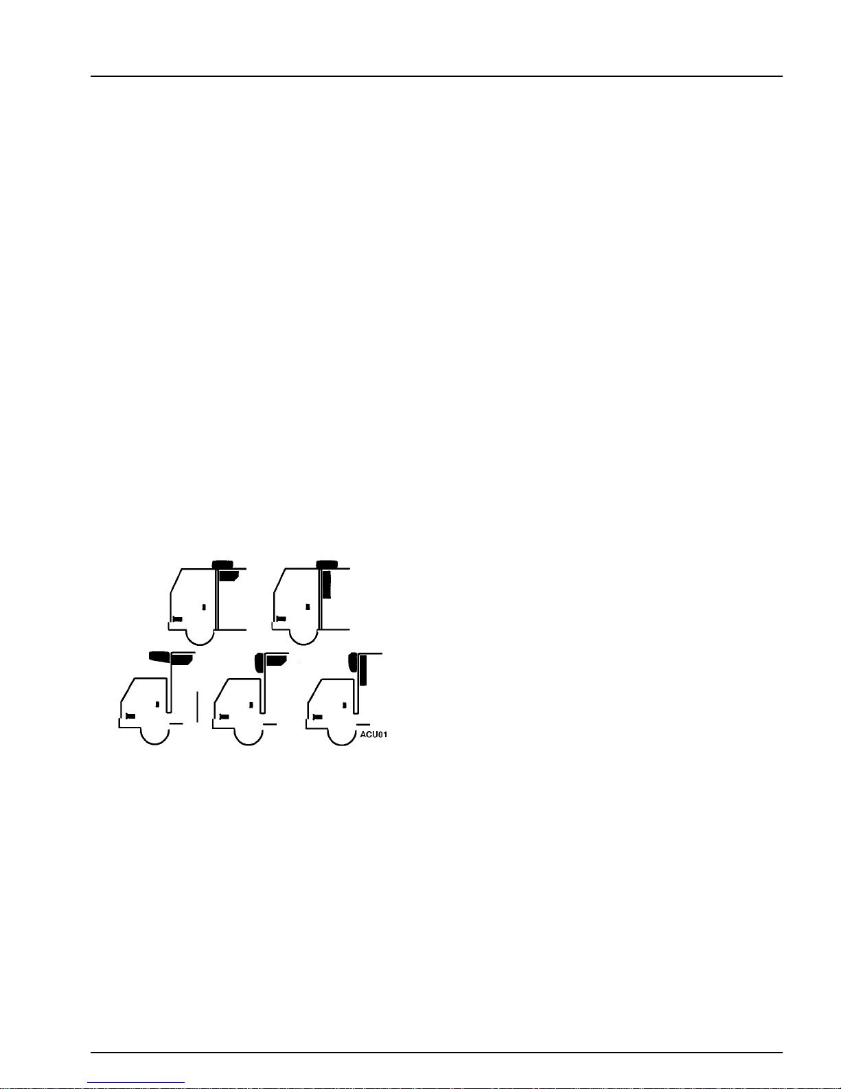
The condenser has a unique design that allows it to be
mounted horizontally or vertically, on the roof or on the
front of the truck box.
The evaporator is mounted inside the truck box. Funnel and
thin-line evaporators are available. The funnel evaporator
mounts on the ceiling or the front wall. The thin-line evaporator mounts on the front wall.
The electric standby compressor is connected in parallel
with the engine-driven compressor. The engine compressor
is driven by a belt from the engine. Th e standb y compres sor
is driven by a belt from the electric motor. Both compressors use the same refrigeration system circuit. Check valves
isolate one compressor from the other during operation.
Compressor operation is controlled by the thermostat,
which energizes the compressor clutch during engine operation or starts the electric motor and energizes the compressor clutch on electric standby operation. The refrigeration
system is protected by a high pressure cutout switch and a
low pressure cutout switch.
The control circuits operate on 12 volts dc supplied by the
truck battery for over-the-road operation. On standby operation, the power is rectified from an ac transformer.
The cab control box is mounted in the truck cab. It contai ns
the On-Off key, Manual Defrost key, thermometer, thermostat, and indicator lights.
Liquid Injection System
Condenser and Evaporator Configurations
The compressor is mounted on and driven by the truck
engine. Refrigeration hoses or lines are used to connect the
condenser, the evaporator and the compressor. Model 20
units have another compressor and an electric motor
mounted in the condenser section for electric standby
operation.
If the discharge gas leaving the engine driven compressor
reaches a temperature of 230 ± 5 F (110 ± 3 C), the liquid
injection switch closes, providing voltage to the liquid injection solenoid. The solenoid opens a valve, allowing liquid
refrigerant to flow from the liquid line near the receiver outlet valve to the metering orifice attached to the suction fitting at the compressor. As the refrigerant passes through the
metering orifice it expands and evaporates, cooling the suction gas entering the compressor. This cooling effect is
transferred to the dischar ge gas lea ving th e compresso r from
the adjacent cavity in the compressor head. When the discharge gas is cooled to 2 00 ± 5 F (9 3 ± 3 C), the liquid injection switch opens, the liquid injection solenoid v alve closes
and refrigerant no longer flows through the liquid injection
system.
7
Page 16

Unit Description (Rev 1/99)
Oil Separator
An oil separator is a standard feature. It separates compressor oil from refrigerant vapor and returns the oil to the compressor through the oil fill hole by using a special adapter.
The oil separator helps provide positive oil return at high
compressor speeds and low operating temperatures. This
feature enhances compressor lubrication and extends compressor life. Units built after November 1996 will be located
in the condenser section. Refer to photo on page 12 and
drawing on page 61.
UNIT OPERATION
These units shift between cool, null, and heat (optional) to
maintain the box temperature at the thermostat setpoint.
The operating modes are: cool, null, heat (optional), and
defrost.
Engine Operation
The thermostat controls the operation of the unit by energizing and de-energizing the power relay and the heat relay.
The thermostat places the unit in cool by energizing the
power relay. The thermostat places the unit in null by deenergizing all the relays. The thermostat places the unit in
heat by energizing the heat relay .
When the power relay is energized, power flows to energize
the fan relay and the compressor clutch through normally
closed contacts in ER2.
When the heat relay is energized, it closes contacts that
energize the fan relay, the water pump, and the water valve.
When the fan relay is energized, it closes contacts that energize the condenser and evaporator fans. The condenser fan
is also controlled by the condenser fan pressure switch.
This normally open switch monitors the compressor discharge pressure. When the discharg e pressure rises to 180 ±
10 psi (1241 ± 69 kPa), the switch closes and energizes the
condenser fan. When the discharge pressure drops to 130 ±
10 psi (896 ± 69 kPa), th e swit ch opens and de-ener gi zes the
condenser fan.
Electric Standby Operation
During electric standby operation, the thermostat controls
the operation of the unit by energizing and de-energizing the
power relay, the electric relays, and the heat contactor. The
thermostat places the unit in cool by energizing the power
relay and the electric relays.
The thermostat places the unit in null by de-energizing all
the relays and contactors. The thermostat places the unit in
heat by energizing the heat contactor.
When the power relay and the electric relays are energized,
they close contacts that energize the fan relay, the motor
contactor, and the electric standby compressor clutch.
When the heat contactor is energized, it energizes the electric evaporator heaters and the fan relay.
Cool
The thermostat shifts the unit to cool at temperatures more
than 5.4 F (3 C) above the thermostat setpoint. The thermostat keeps the unit running in cool until the temperature falls
to the thermostat setpoint.
During engine operation the engine compressor and the
evaporator fans operate while the unit is in co ol. During
electric operation, the electric motor, the electric standby
compressor, and the evaporator fans operate while the unit
is in cool.
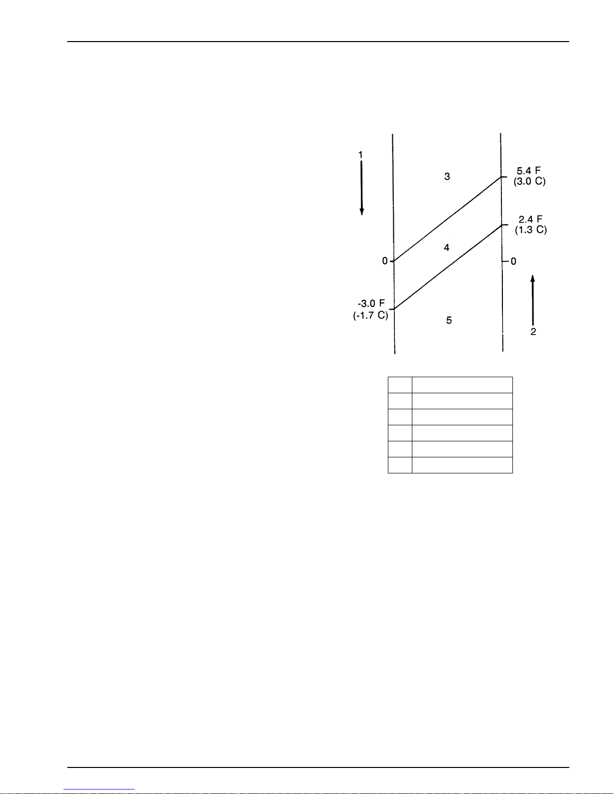
Null
The thermostat shifts the unit from cool to null at the thermostat setpoint. The thermostat shifts the unit from null to
heat at 3 F (1.7 C) below the thermostat setpoint. The thermostat shifts the unit from heat to null at 2.4 F (1.3 C) above
the thermostat setpoint. The thermostat shifts the unit from
null to cool at 5.4 F (3 C) above the thermostat setpoint.
8
Page 17
Heat (Optional)
The thermostat shifts the unit to heat at temperatures more
than 3 F (1.7 C) below the thermostat setpoint. Th e therm ostat keeps the unit running in heat un til the temp erature ris es
to 2.4 F (1.3 C) above the thermostat setpoint. During
engine operation, the water pump and the evaporator fans
operate while the unit is in heat.
During electric operation, the evaporator heaters and the
evaporator fans operate while the unit is in heat.
Defrost
The defrost cycle can be initiated any time the evaporator
coil temperature is below 42 F (5.6 C). Defrost is initiated
automatically by the defrost timer, or manually by pressing
the Manual Defrost switch.
Unit Description (Rev 1/99)
AGA329
Initiating defrost energizes the defrost relay. This energizes
the hot gas solenoid to route hot gas to the evaporator, and
de-energizes the fan relay to stop the evaporator and condenser fans.
The unit runs in defrost until the evaporator coil temperature rises to 52 F (11.1 C), causing the defrost termination
switch to open. This de-energizes the defrost relay and terminates defrost. If the defrost termination switch does not
open in less than 45 minutes, the defrost timer will terminate the defrost cycle 45 minutes after is was started.
0Setpoint
1 Temperature Drop
2 Temperature Rise
3Cool
4Null
5 Heat (Optional)
(1) Shifts from Null to Cool if not previously in Heat
(2) Shifts from Null to Heat if not previously in Cool
Thermostat Algorithm
UNIT FEATURES
• Digital Thermometer
• Electronic Thermostat
• Defrost Timer
• Hot Gas Defrost
• Defrost Termination Switch
• Liquid Injection System
9
Page 18

Unit Description (Rev 1/99)
• Manual Defrost Key
• Suction Pressure Regulator
• Oil Separator
• Six Cylinder Compressor
• R-134a
Unit Features (continued)
• Standby Electric Motor and Six Cylinder Standby
Compressor (Model 20 only)
• Refrigerant Flow Controlled Between Compressors by
Discharge Check Valve (Model 20 only)
PROTECTION FEATURES
• Control Circuit Fuses
• Refrigerant High Pressure Cutout
• Refrigerant Low Pressure Cuto ut
• Heat, Truck Engine and Electric Standby Heater St rips
(Model 20)
• Paint, Special Color
• 24 V dc Converter
• R-404A Dealer Installed
SERIAL NUMBER LOCATIONS
Condenser: Roadside.
Evaporator: Roadside panel.
Compressor: Nameplate on compressor body.
Standby Motor: Nameplate on motor.
• Refrigerant High Pressure Relief Valve
• Power Cord Warning Light (in Cab Control Box)
• Overload Relay Protection for Electric Standby Motor
(Model 20 o nl y)
• Transformer Fuses (Model 20 only)
OPTIONAL FEATURES
• Electric Motors (Model 20 only)
115 Volt/1 Phase/60 Hz
220 Volt/1 Phase/50 Hz
230 Volt/1 Phase/60 Hz
220 Volt/3 Phase/50 Hz
230 Volt/3 Phase/60 Hz
400 Volt/3 Phase/50 Hz
• Heat, Truck Engine (Model 10)
10
Page 19
Unit Description (Rev 1/99)
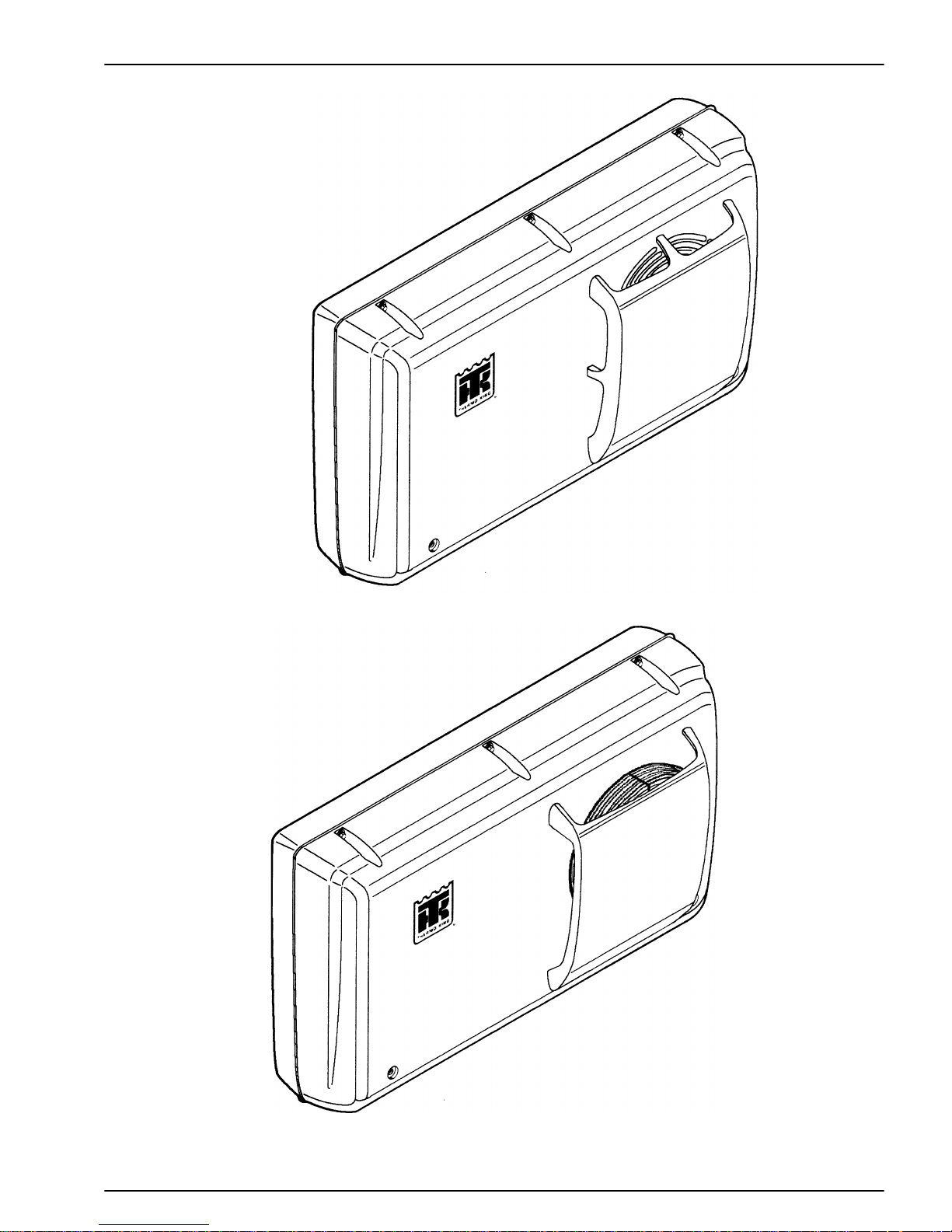
AGA339
Vertical Mounted Condenser (Early Model)
AGA673
Vertical Mounted Condenser (Later Model)
11
Page 20
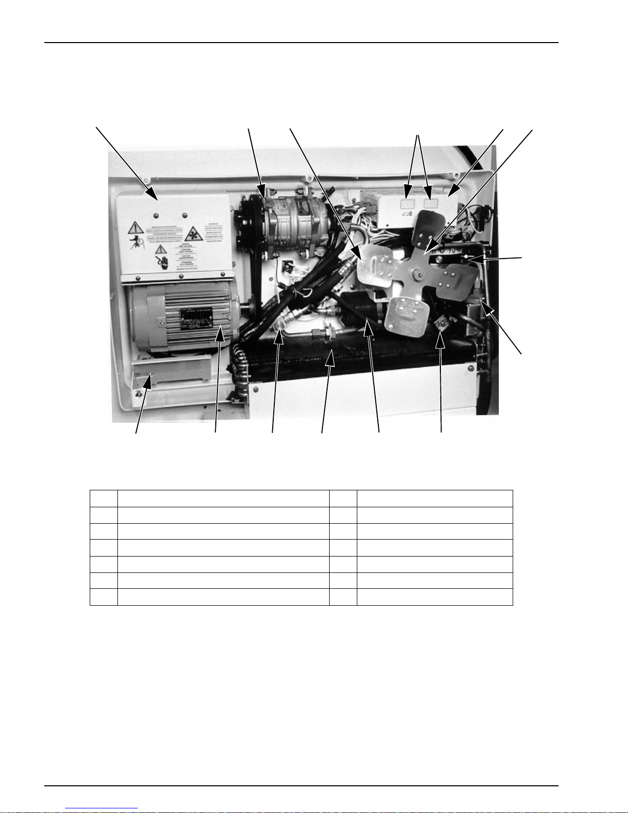
Unit Description (Rev 1/99)
12 4356
7
14
12
9101113
1. High Voltage Box 8. Oil Separator
2. Compressor 9. Liquid Injection Solenoi d
3. Hot Gas Solenoid (Behind Fan Blade ) 10. Drier
4. Hourmeters Location (Optional) 11. Condenser Coil
5. Low Voltage Box 12. Check Valve Assembly
6. Condenser Fan 13. Motor (Model 20 only)
7. Receiver Tank 14. 24 Volt Converter
Condenser Components—Front/Top View (Starting 1997)
8
AEA825
12
Page 21
Unit Description (Rev 1/99)
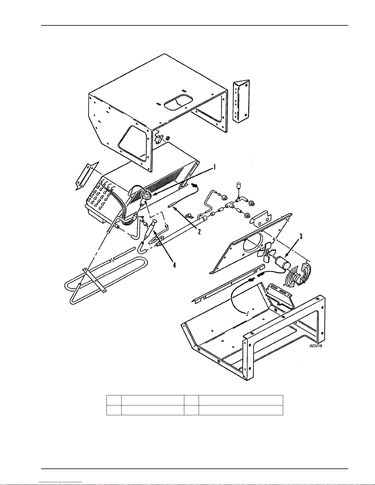
1. Expansion Valve 3. Fan Motor
2. Thermostat Sensor 4. Suction Pressure Regulator
Funnel Evaporator
13
Page 22
Unit Description (Rev 1/99)
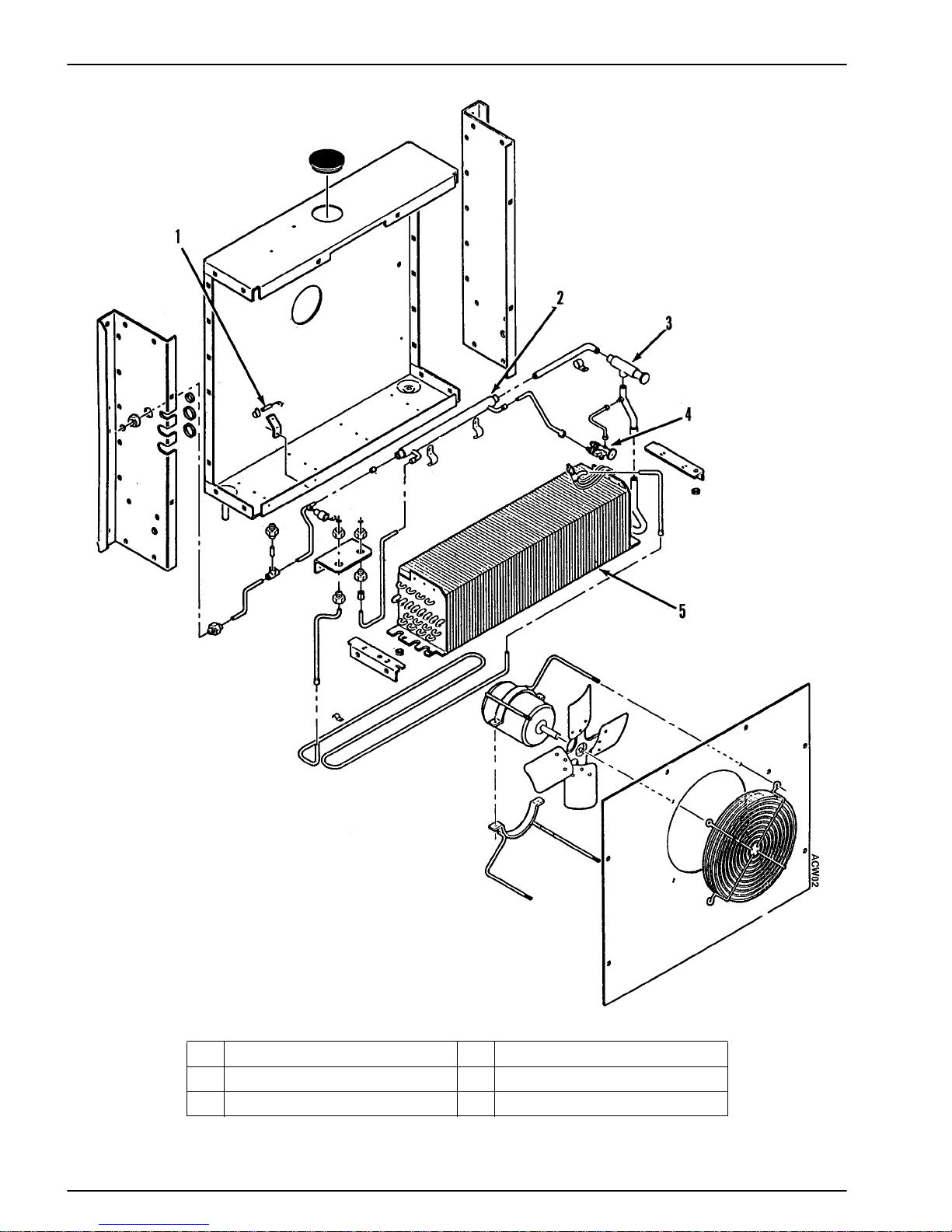
1. Thermostat Sensor 4. Expansion Valve
2. Heat Exchanger 5. Evaporator Coil
3. Suction Pressure Regulator
Thin-Line Evaporator
14
Page 23
Unit Description (Rev 1/99)
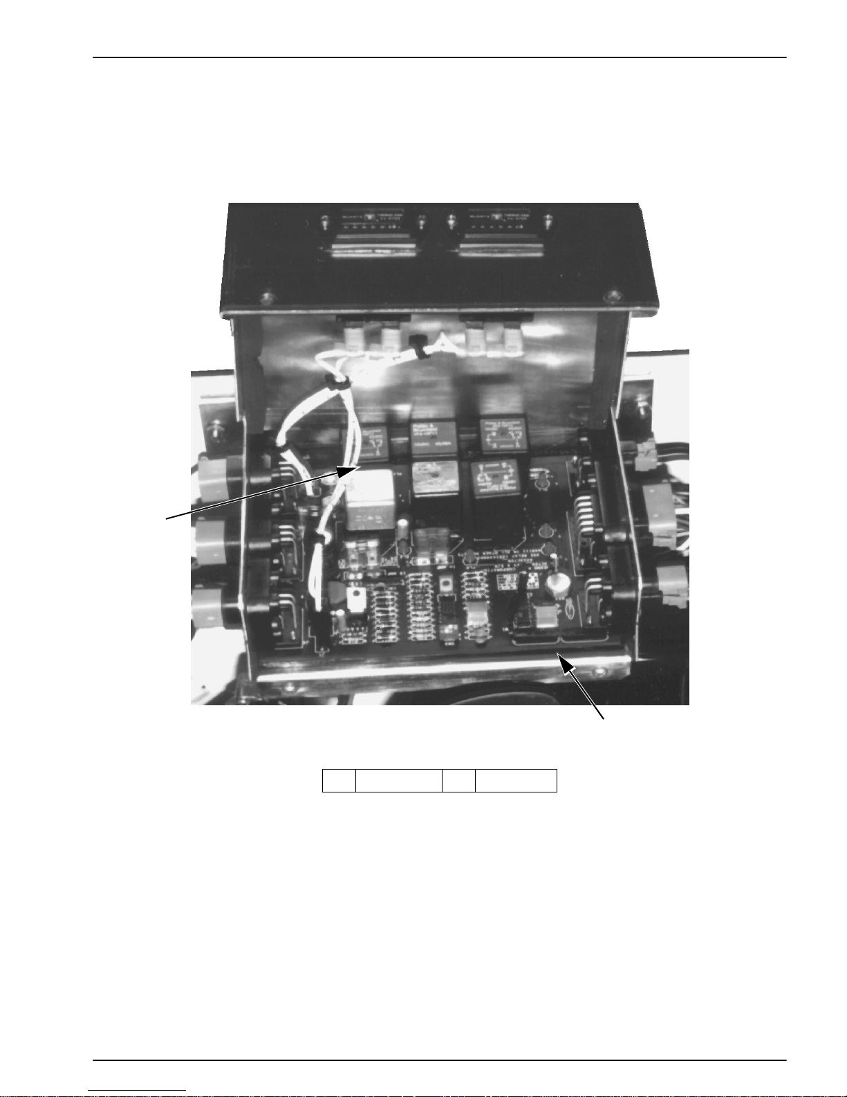
1
AEA667
2
1. Relays 2. PC Board
Low Voltage Box—Pre-1996
15
Page 24
Unit Description (Rev 1/99)
9
8
7
1
6
5
4
3
AEA660
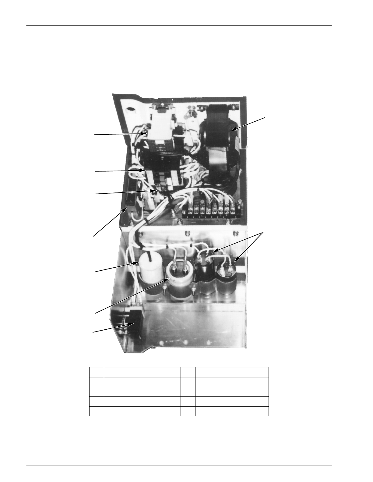
1. Transformer 6. Transformer Fuse
2. Motor Start Capacitors 7. Overload Relay
3. Motor Start Relay 8. Motor Contactor
4. DC Power Filter Capacitor 9. Heat Contactor (Optional)
5. Motor Run Capacitor
2
High Voltage Box—Pre-1997
16
Page 25
Unit Description (Rev 1/99)
1
9
8
7
6
AEA826
2345
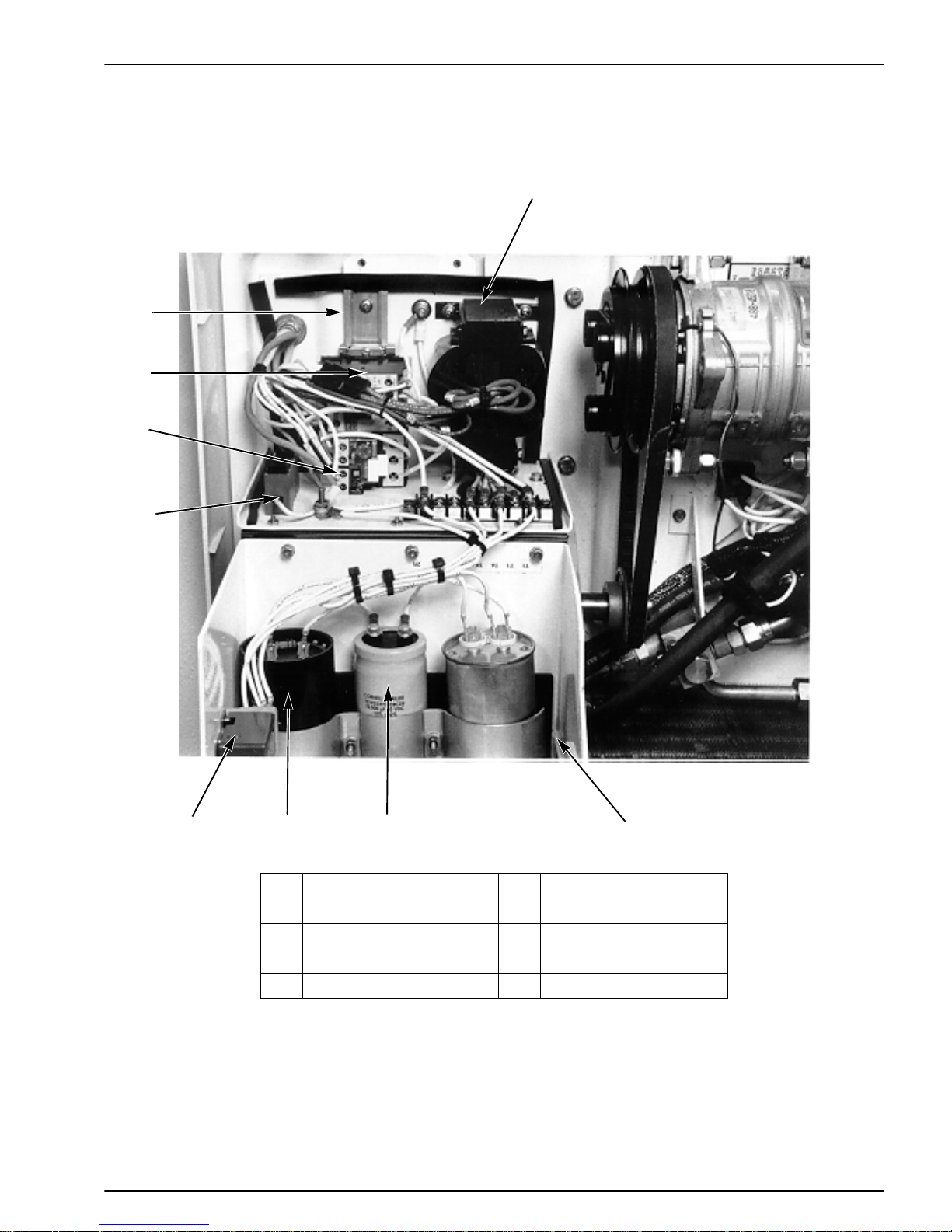
1. Transformer 6. Transformer Fuse
2. Motor Start Capacitors 7. Overload Relay
3. DC Power Filter Capacitor 8. Motor Contactor
4. Motor Run Capacitor 9. Heat Contactor (Optional)
5. Motor Start Relay
High Voltage Box—Starting 1997
17
Page 26
Unit Description (Rev 1/99)
1
2
3
8
4
5
7
6
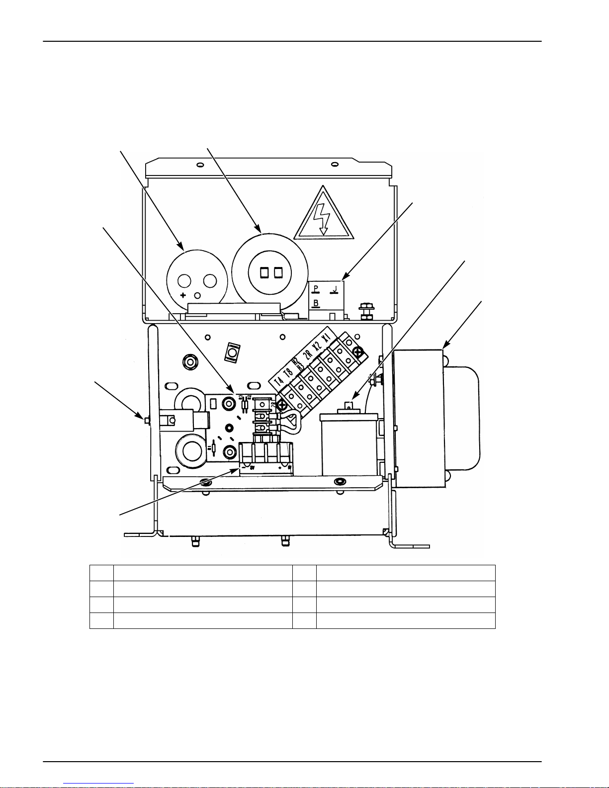
1. D.C. Power Filter Capacitor 5. Transformer
2. Motor Starting Capacitor 6. Motor Contactor
3. Motor Start Relay 7. Fuse and Fuseholder
4. Motor Run Capacitor 8. Motor Protector
High Voltage Box - Typical for Single Phase P97
AGA340
18
Page 27
Unit Description (Rev 1/99)
1
2
3
5
4
AGA345
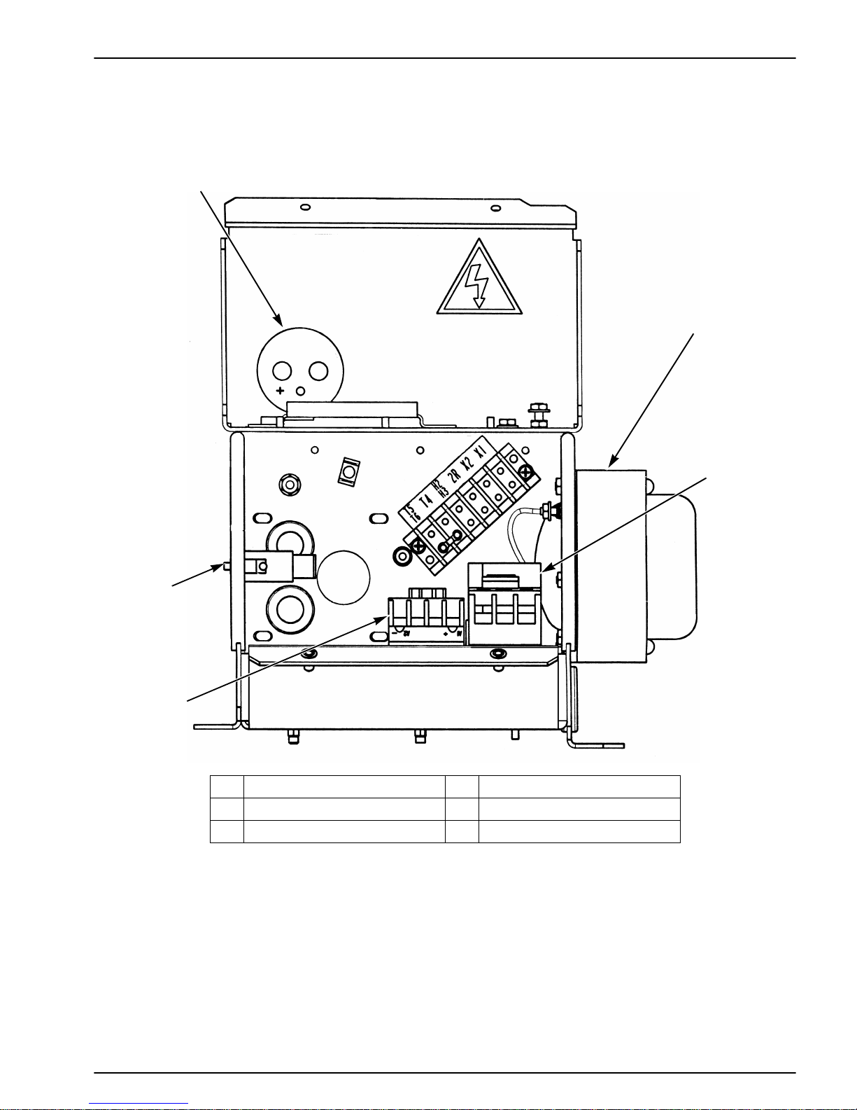
1. D.C. Power Filter Capacitor 4. Motor Contactor
2. Transformer 5. Fuse and Fuse Holder
3. Overload Relay
High Voltage Box - Typical fo r 3 Phase P97
19
Page 28
Unit Description (Rev 1/99)
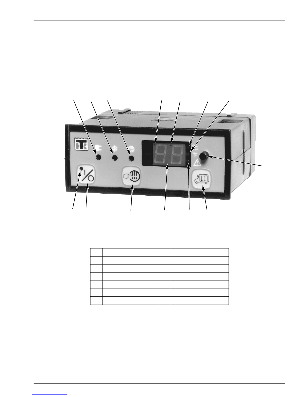
123 4 5 6 7
91011121314
1. Power Cord Indicator 8. Thermostat Dial
2. Running Indicator 9. Setpoint Key
3. Defrost Indicator 10. AC Overload Indicator
4. Heat Indicator 11. Digital Display
5. Cool Indicator 12. Manual Defrost Key
6. Celsius Indicator 13. On-Off Key
7. Fahrenheit Indicator 14. On Indicator
Cab Control Box—M10 Pre-1997
8
AEA661
20
Page 29
Unit Description (Rev 1/99)
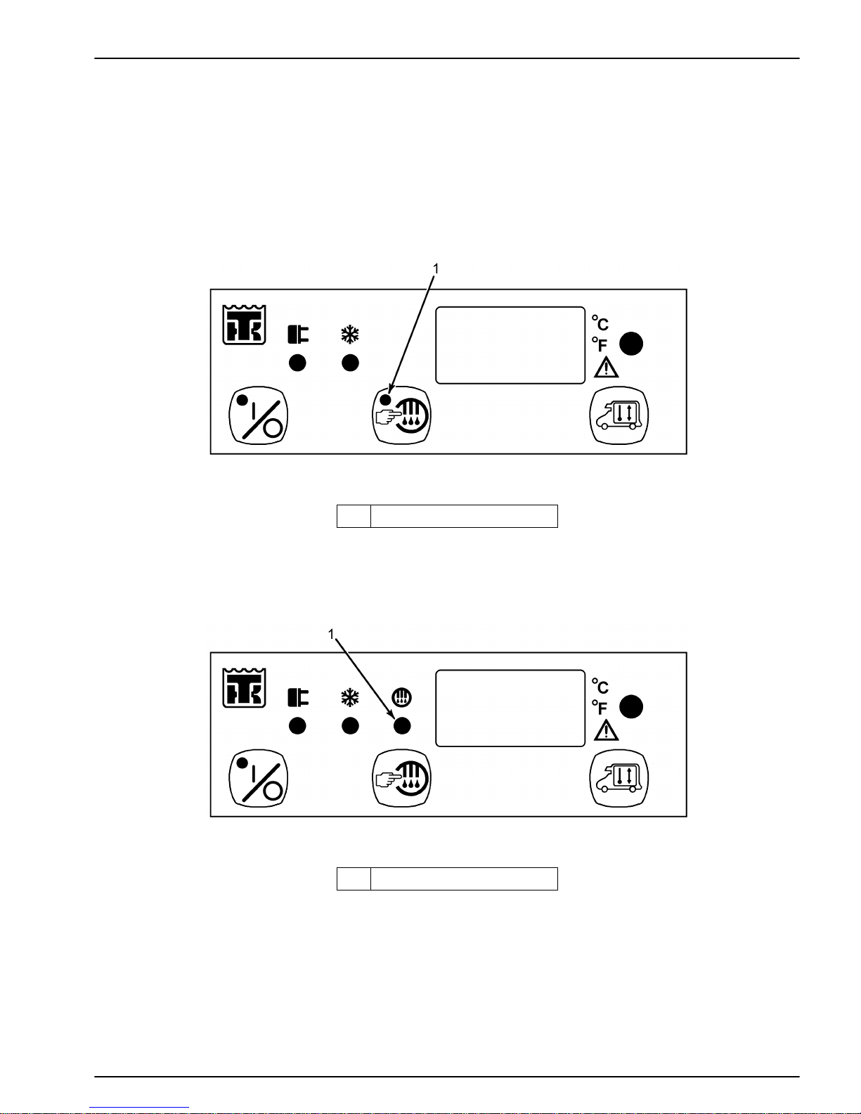
NOTE: The M13 and M10 cab boxes a re identified by th e position of the d efrost indicator li ght. On the M13 cab box the
defrost indicator light is po sitioned on the def rost key. On the M10 cab box t he defrost indica tor light is pos itioned left of
the digital display. Refer to the following illustrations. Refer to Service Bulletin 177.
AEA835
1. Defrost Indicator Light
M13 Cab Box—TK No. 45-1780
1. Defrost Indicator Light
M10 Cab Box—TK No. 45-1705
AEA836
21
Page 30

22
Page 31

Operating Instructions
UNIT CONTROLS
Cab Control Box
1. ON-OFF KEY. Press this key to turn the unit ON and
OFF.
2. ON INDICATOR. When this light is on, it indicates
that the unit is turned ON. When this light is off, it
indicates that the unit is turned OFF.
3. POWER CORD INDICAT OR. When this light is on, it
indicates that the unit is connected to an electric
standby power source.
4. RUNNING INDICATOR. When this light is on, it
indicates that the unit is running.
5. MANUAL DEFROST KEY. Press this key to start a
defrost cycle. The unit will not defrost unless the
defrost termination switch is closed (evaporator coil
temperature below 42 F [5.6 C]).
6. DEFROST INDICATOR. When this light is on, it indicates that the unit is in defrost.
7. DIGITAL DISPLAY. This display is active only when
the unit is turned on. The thermometer reading (return
air sensor temperature) normally appears on the display. Pressing the setpoint key causes the thermostat
setpoint to appear on the di splay for 10 t o 15 seconds.
12. AC OVERLOAD INDICATOR. When this light is on,
it indicates that the overload relay has opened. This
indicator must be reset by pressing the On-Off Key
after allowing time for the overload relay to cool.
13. SETPOINT KEY. Press this key to make the thermostat setpoint appear on the digital display. The thermostat setpoint will remain on the display for 10 to 15
seconds after the key is released. This gives the operator time to adjust the thermostat setpoint.
14. THERMOSTAT DIAL. Turn this dial to adjust the
thermostat setpoint.
NOTE: The Thermostat Dial will change the thermostat setpoint without pressing the Setpoint Key.
Low Voltage Box
1. DEFROST TIMER. The defrost timer is built-in to the
PC board. It can automatically initiat e or terminate a
defrost cycle if necessary. The initiation interval is
adjustable from 1 hour to 10 hours. The termination
interval is set at 45 minutes. Refer to the Electrical
Maintenance section for more information about the
defrost timer.
2. CONTROL RELAYS. Six control relays are located
on the PC board. These relays are used to control the
operation of the unit.
8. HEAT INDICATOR. When this light is on, it indicates
that the unit is running in heat.
9. COOL INDICATOR. When this light is on, it indicates
that the unit is running in cool.
10. CELSIUS INDICATOR. When t his light is on, it indicates that the temperature is being displayed in degrees
Celsius.
11. FAHRENHEIT INDICATOR. Wh en this light is o n, it
indicates that the temperature is being displayed in
degrees Fahrenheit.
3. ENGINE HOURMETER (Optional). This hourmeter
records the amount of time the unit runs on engine
operation.
4. ELECTRIC HOURMETER (Model 20) (Optional).
This hourmeter records the amo unt o f time the un it runs
on electric standby operation.
High Voltage Box (Model 20)
1. MOTOR CONTACTOR. The motor contactor is used
to control the operation of the electric motor that drives
the electric standby compressor .
23
Page 32

Operating Instructions (Rev 1/99)
2. HEATER CONTACTOR (Optional). The heater contactor is used to control the operation of the optional
electric evaporator heaters.
Other Controls
1. DEFROST TERMINATION SWITCH. This temperature sensitive switch is located on the evaporator coil.
It closes to enable defrost when the evaporator coil
temperature falls below 42 F (5.6 C).
The switch opens to terminate, or disable, defrost when
the evaporator coil temperature rises to 52 F (11.1 C).
2. CONDENSER FAN PRESSURE SWITCH. This pressure sensitive switch is located on the receiver tank.
When the pressure in the receiver tank rises above 180
psi (1241 kPa), the switch closes to energized the condenser fan. When the pressure in the receiver tank falls
below 130 psi (896 kPa), the switch opens to de-energize the condenser fan.
3. LIQUID INJECTION SWITCH. This temperature sensitive switch is located on the discharge fitting of the
truck engine compressor. When the discharge temperature rises above 230 F (110 C), the switch closes to
open the liquid injection solenoid. When the disch arge
temperature falls below 200 F (93 C), the switch opens
to close the liquid injection solenoid.
4. SUCTION PRESSURE REGULATOR VALVE. This
valve is located in the suction line in the evaporator. It
limits the suction pressure at the comp ressor. The normal pressure setting for this valve is 18 to 20 psi (124 to
138 kPa).
UNIT PROTECTION DEVICES
1. PC BOARD FUSES. Five fuses are located on the PC
board in the low voltage box.
F1 This 15 amp fuse protects the circuit to the con-
denser fan m otor.
F2 This 15 amp fuse protects the circuit to the evapo-
rator fan motor.
F3 This 10 amp fuse protects the circuit to the power
relay and the heat relay.
F4 This 3 amp fuse protects the circuit from the trans-
former output to the cab control box.
F5 Defros t Circ uit Fuse. 1 Amp
F6 A 40 amp fuse protects the battery circuit.
F7 A 10 amp fuse protects transformer motor circuit
for 115V/1 Ph/60 Hz, 230V,1 Ph/60 Hz, and 230V/
1 Ph/50 Hz. A 4 amp fuse protects the transformer
motor circuit for 230V and 400V at 3 Ph, 50 units
and 230V, 3 Ph, 60 Hz units.
2. CIRCUIT BR EAKER. A 40 a mp circuit breaker or 40
amp fuse protects the circuit from the vehicle battery to
the unit.
3. HIGH PRESSURE CUTOUT SWITCH. This pressure
sensitive switch is located on the receiver tank. If the
pressure in the receiver tank rises above 350 psi (2413
kPa) for R-134a systems or 470 psi (3241 kPa) for R404A systems, the switch opens the circuit to the
power relay, which stops the unit.
NOTE: This operation is for units with printed circuit
board manufactured prior to 3-25-96 (s ee “P.C. Bo ar d
P/N 41-776 (First Version)” on page 38).
When the HPCO opens on models using printed ciruit
board manufactured between 3-26-96 and 5-21-96,
see “P.C. Board P/N 41-1619 (Second Version)” on
page 39 or after 5-21-96 (see “P.C. Board P/N 411812 (Third Version)” on page 40) the HPCO will
cycle the compressor clutch only.
4. LOW PRESSURE CUTOUT SW ITCH. This p ressure
sensitive switch is located on the suction line in the
evaporator. If the pressure in the suction line falls
24
Page 33

Operating Instructions (Rev 1/99)
below 5 to 11 in. Hg of vacuum (-17 to -37 kPa), the
switch opens the circuit to the power relay, which stops
the unit.
NOTE: This operation is for units with printed circuit
board manufactured p rior to 3-25-96 (see “P.C. Board
P/N 41-776 (First Vers ion)” on page 38).
When the LPCO opens on models using printed cirucit board manufactured between 3-26-96 and 5-21 -96,
see “P.C. Board P/N 41-1619 (Second Version)” on
page 39 or after 5-21-96 (see “P.C. Board P/N 411812 (Third Version)” on page 40) the HPCO will
cycle the compressor clutch only.
5. FUSE PLUG. The fuse plug is located on the receiver
tank. It opens to relieve the pressure in the refrigeration system if the pressure becomes excessive. If the
fuse plug has opened, it must be replaced. It cannot be
reused.
6. OVERLOAD RELAY (Model 20). This auto reset
relay protects the electric motor that drives the electric
standby compressor. The overload relay opens the circuit to the cab control box, which de-energizes the
motor contactor and the electric motor if the motor
overloads for any reason (e.g., low line voltage or
improper power supply) during electric standby operation. When the overload relay opens, it illuminates the
AC overload indicator.
7. TRANSFORMER FUSE (Model 20). This fuse is
located in the high voltage box. The 115 volt, single
phase, 60 Hz unit has a 10 amp f use. Al l oth er uni ts use
a 4 amp fuse.
inspection is not a substitute for regularly scheduled maintenance inspections, it is an important part of t he preventive
maintenance program designed to head off operating problems before they happen.
1. LEAKS. Inspect for refrigerant leaks and worn refrigerant lines.
2. BELTS. Inspect for cracks, wear and proper tensions.
3. ELECTRICAL INSPECTION. The electrical connections should be securely fastened. Wires and terminals
should be free of corrosion, cracks or moisture.
4. DEFROST DRAINS. Check the defrost drain hoses
and fittings to make sure that they are open so condensate can run out during defrost. Check the bottom end
of each drain hose to make sure that it is not plugged or
crushed.
5. STRUCTURAL INSPECTION. Visually check for
physical damage.
6. REFRIGERANT CHARGE. Check the receiver tank
sight glass for the proper charge level.
Starting the Unit
Model 10 Units
1. Start the truck engine.
2. Press the On-Off key in the cab control box to turn the
unit ON.
3. Adjust the thermostat to the proper setting.
Model 20 Units
UNIT OPERATION
Bi-monthly Pre-Trip Checks
The following bi-monthly pre-trip inspection should be
completed before loading the truck. While the bi-monthly
Engine Operation
1. Start the truck engine.
2. Press the On-Off Key in the cab control box to turn the
unit ON.
25
Page 34

Operating Instructions (Rev 1/99)
3. Adjust the thermostat to the proper setting.
NOTE: The power cord indicator will come on if the
unit is connected to an electric standby power supply.
Electric Standby Operation
1. Connect the electric standby power supply to the unit’s
power receptacle. Make sure that the power supply has
the proper voltage and phasing.
2. Press the On-Off Key in the cab control box to turn the
unit ON.
3. Adjust the thermostat to the proper setting.
NOTE: The power cord indicator will come on while
the unit is connected to an electric standby power
supply.
Adjusting the Thermostat
The thermometer reading (return air sensor temperature)
normally appears on the digital display while the unit is
turned ON. Pressing the Setpoint Key causes the thermostat
setpoint to appear on the di splay for 10 to 15 seconds.
1. Press the Setpoint Key to display the setpoint. The setpoint will appear on the display for 10 to 15 seconds.
2. PRECOOLING. With the thermostat set at the correct
temperature, allow the unit to run for one-half to one
hour (longer if possible) before loading the truck. Precooling will remove residual body heat and moisture
from the box interior and provide a good test of the
refrigeration system.
3. DEFROST. When the unit has finished pre-cooling the
truck interior (the evaporator temperature has dropped
below 42 F (5.6 C), initiate a defrost cycle with the
Manual Defrost switch. The defrost cycle should end
automatically.
Loading Procedure
1. Make sure that the unit is OFF before opening the doors
to minimize frost accumulation on the evaporator coil
and heat gain in the truck. (The unit may be running
when the truck is being loaded from a warehouse with
door seals.)
2. Spot check and record the load temperature while loading. Especially note any off-temperature product.
3. Load the product so there is adequate space for air circulation completely around the load. DO NOT block
the evaporator inlet or outlet.
2. Turn the Thermostat Dial to adjust the setpoint to the
proper setting while the setpoint is being displayed.
3. After the thermometer reading appears on the display,
press the Setpoint Key to check the setpoint.
NOTE: The Thermostat Dial will change the setpoint
without pressing the Setpoint Key. Do not turn the
Thermostat Dial without checking the setpoint.
After Start Inspection
1. THERMOSTAT. Adjust the thermostat setting above
and below the box temperature to check the thermostat
operation (see Operating Modes).
4. Products should be precooled before loading. Thermo
King units are designed to maintain loads at the temperature at which they are loaded. Transport refrigeration
units are not designed to pull hot loads down t o te mp erature.
Post Loading Procedure
1. Make sure that all the doors are closed and locked.
2. Adjust the thermostat to the desired temperature setpoint.
3. Start the unit.
26
Page 35

4. One-half hour after loading, def rost the uni t by momentarily pressing the Manual Defrost switch. If the coil
temperature has dropped below 42 F (5.6 C), the unit
will defrost. The defrost cycle should stop automatically.
Bi-monthly Post Trip Checks
1. Wash the unit.
2. Check for leaks.
3. Check for loose or missing hardware.
4. Check for physical damage to the unit.
Operating Instructions (Rev 1/99)
27
Page 36

28
Page 37

Electrical Maintenance
UNIT WIRING
Periodically inspect the unit wiring and the wire harnesses
for loose, chafed or broken wires to protect against unit malfunctions due to open or short circuits.
CAB CONTROL BOX
Selecting the Temperature Scale
The temperature readings can be displayed in eith er the Celsius scale or the Fahrenheit scale. Dip switch 3, located
inside the cab control box, is used to select which scale is
displayed. In dicator lights next to the digital display show
which scale has been selected. Place dip switch 3 in the ON
position to display temperatures in degrees Celsius.
Place dip switch 3 in the OFF position to display temperatures in degrees Fahrenheit. To change the temperature
scale selection:
1. Remove the cover from the back of the cab control box.
2. Place dip switch 3 in the proper position.
ON for Celsius
OFF for Fahr e nheit
3. Replace the cover.
Selecting the Setpoint Range
The setpoint range can be set at either -26 to 86 F (-32 to 30
C) or -8 to 86 F (-22 to 30 C). Dip switches 1 and 2, located
inside the cab control box, are used to select the setpoint
range. Place dip switches 1 and 2 in the ON position for a
setpoint range of -26 to 86 F (-32 to 30 C). Place dip
switches 1 and 2 in the OFF positio n for a setpo int range of
-8 to 86 F (-22 to 30 C). To change the setpoint range selec-
tion:
1. Remove the cover from the back of the cab contro l box.
2. Place dip switches 1 and 2 in the proper position.
ON for a setpoint range of -26 to 86 F (-32 to 30 C).
OFF for a setpoint range of -8 to 86 F (-22 to 30 C).
3. Replace the cover.
1. Dip Switches
Back of Cab Control Box with Cover Removed
29
Page 38

Electrical Maintenance (Rev 1/99)
NOTE: Do not run a R-1 34a un i t t o -2 6 F (-3 2 C). R-404A
units may be operated at -24 F (-32 C).
Setpoint Differential Adjustment
Adjust the thermostat setpoint differential to 4 F (2 C).
1. Remove the cab control box from its bracket.
2. Remove the cover from th e back o f the cab contro l bo x.
3. Turn the adjusting potentiometer to the 12 o’clock position.
4. Replace the cover and place the cab contro l box back in
its bracket.
1. 1 Amp Fuse
2. 12/24 Volt Jumper
3. Main Harness Plug
4. Dip Switches
5. Sensor Plug
6. Setpoint Differential Potentiometer Set to 12 o’cl oc k pos it ion
Adjust Setpoint Differential
30
Page 39

Electrical Maintenance (Rev 1/99)
Testing the Cab Control Box
The cab control box contains the thermometer and the thermostat. The thermometer and the thermostat share the same
digital display and use the same sensor. The thermometer
displays the sensor temperature. The thermostat compares
the sensor temperature with the setpoint to determine the
unit’s operating mode. The sensor is normally located in the
evaporator return airflow.
Thermometer
The range for the thermometer is -40 to 99 F (-40 to 38 C).
Normally the thermometer reading appears on the digital
display. Pressing the Setpoint key causes the thermostat
setpoint to appear on the digital display for 10 to 15
seconds.
Thermostat
The setpoint range for the thermostat is -26 to 86 F (-32 to
30 C) or -8 to 86 F (-22 to 30 C). The thermostat setpoint
appears on the digital display when the Setpoint key is
pressed. Turning the thermostat dial changes the setpoint.
The thermostat controls the operation of the unit by controlling the power relay, the heat relay, and the electric relays.
Initial Digital Display Test
1. Turn the un it ON. Note what ap pears o n the digital dis play. This is the temperature display.
a. Normal Display (-40 to 199 F [-40 to 38 C])
b. Blank Display
c. Erratic Display
2. Press the Setpoint key and note what appears on the
digital display. This is the setpoint display.
a. Normal Display (-26 to 8 6 F [-32 to 30 C])
b. Blank Display
c. Erratic Display
d. No Change
3. Refer to the Display Diagnosis Chart to see what to
check next.
Check Power—Engine Operation
1. Make sure that the condenser cover is on the unit.
2. Remove the cover from the back of the cab contro l box.
Temperature
Display
3. Start the truck engine and turn the unit ON.
Display Diagnosis Chart
Setpoint Display
Normal Display Blank Display Erratic Display No Change
Normal Display
Blank Display Check Sensor Check Power Check Power Check Power
Erratic Display Check Sensor Check Power Check Power Check Power
No Problem Faulty Cab
Control Box
Faulty Cab
Control Box
Faulty Cab
Control Box
31
Page 40

Electrical Maintenance (Rev 1/99)
Steps 4 and 5 refer to Wiring Diagram 5D44456 and Schematic Diagram 5D44455.
4. Check the voltage between the 2R3 circuit (pin 3) and
the CH circuit (pin 9) in the connector on the back of
the cab control box. Battery voltage (12 volts).
5. If battery voltage is not present, check the wiring and
connectors in the circuit to the vehicle accessory terminal 2R3 and SW2 on the PC board. Make sure that the
vehicle accessory terminal has power.
Steps 6 and 7 refer to Wiring Diagram 5D46190 and Schematic Diagram 5D46179.
6. Check the voltage between the ACD circuit (pin 3) and
the CH circuit (pin 9) in the connector on the back or
the cab control box. Battery voltage (12 volts).
7. If the battery voltage is not present, check the wiring
and connectors in the circuit to the vehicle accessory
terminal, ACD. Make sure that the vehicle accessory
has power.
Check Power—Electric Standby Operation
proper output voltages (X3-X4) and make sure that the
electric standby power supply is turned ON.
Steps 6 and 7 refer to Wiring Diagram 5D46190 and Schematic Diagram 5D46179.
6. Check the voltage between 2R1 (pin 2) and the CH circuit (pin 9) in the connector on the back of the cab control box. Transformer output voltage (12 volts) should
be present.
7. If voltage is not present, check the wiring, connectors
and components to the transformer (L1, L3; 2R2, 2R2;
and F7) fuse. Check the transformer for the proper output voltages (X3-X4) and make sure that the electric
power standby is ON.
Check Sensor
A good sensor should have a resistance of 805 to 825 ohms
at a temperature of 32 F (0 C). To check a sensor:
1. Disconnect the sensor wires form the back of the cab
control box and connect the sensor wires to an accurate
ohmmeter.
1. Make sure that the condenser cover is on the unit.
2. Remove the cover from the back of the cab contro l box.
3. Connect the unit to an appropriate electric standby
power supply and turn the unit ON.
Steps 4 and 5 refer to Wiring Diagram 5D44456 and Schematic Diagram 5D44455
4. Check the voltage between the 2R2 circuit (pin 2) and
the CH circuit (pin 9) in the connector on the back of
the cab control box. Transformer output voltage (12
volts) should be present.
5. If voltage is not present, check the wiring, connectors,
and components in the circuit to the transformer (L1,
L3; 2R2, 2R 1; F5 fuse). Check the t ransforme r for the
2. Remove the sensor from the evaporator and place the
sensor in an ice water bath at 32 F (0 C). Use a reliable
thermometer to confirm the temperature of the ice
water bath. Make sure that the sensor is in the ice water
bath long enough (a few mi nute s) for th e temperatu re to
saturate the sensor.
3. Check the resistance of the sensor. It should be 805 to
825 ohms. If not, check the sensor wires to make sure
that they are not damaged. If the sensor wires are not
damaged, the sensor is defective.
4. If the sensor is not defective, reconnect the sensor wires
to the back of the cab control box and check the thermometer display. If th e thermometer display is not normal, attach a new sensor to the cab control box and
recheck the thermometer display. If thermometer display is still not normal, the cab control box is defective.
32
Page 41

Electrical Maintenance (Rev 1/99)
Faulty Cab Control Box
Before replacing the cab control box make sure that another
problem, such as a l oose wire connection or a bad ground, is
not causing the cab control box to malfunction.
Thermometer Calibration Test
1. Place the sensor in an ice-water bath for a few minutes
and allow the sensor temperature to stabilize.
2. Check the thermometer reading. It should be 32 ± 2 F
(0 ± 1 C).
3. If the thermometer reading is out of calibration, replace
the sensor and repeat the test.
4. If the thermometer reading is still out of calibration, the
cab control box is defective.
Thermostat Switch Sequence Test
This test should be performed during scheduled preventive
maintenance operations. Make sure that the thermometer is
calibrated before performing this test.
NOTE: Press the Setpoint key to display the thermostat
setpoint.
3. Continue to slowly turn the thermostat dial up to raise
the thermostat setpoint about 2 F (1 C) every 5
seconds. When the thermostat setpoint is approximately 3.6 F (2 C) above the thermometer reading, the
Heat Indicator and the Running Indicator should both
come on, the heat relay should energize, and the unit
should shift to heat.
4. Slowly turn the thermostat dial d own to lower the thermostat setpoint about 2 F (1 C) every 5 seconds. When
the thermostat setpoint is equal to the thermometer
reading, the Heat Indicator and the Running Indicator
should both go off, the heat relay should de-energize,
and the unit should shift to null.
5. Continue to slowly turn the thermostat dial down to
lower the thermostat setpoint about 2 F (1 C) every 5
seconds. When the thermostat setpoint is ap proximately
3.6 F (2 C) below the thermometer reading, the Cool
Indicator and the Running Indicator should both come
on, the power relay should ener gize, an d the unit s hould
shift to cool.
If the indicator lights do not come on and go off properly,
and if the unit does not shift operating modes properly, the
cab control box is probably defective.
Engine Operation Test
1. Start the unit on engine operation and set the thermostat
at least 6.3 F (3.5 C) below the thermometer reading.
The Cool Indicator and the Running Indicator should
be on, the Heat In dica to r sho u ld be off, t he po we r rela y
should be energized, the heat relay should be de-energized, and the unit should be running in cool.
2. Slowly turn the thermostat dial up to raise the thermostat setpoint about 2 F (1 C) every 5 seconds. When the
thermostat setpoint is approximately equal to the thermometer reading, the Cool Indicator and the Running
Indicator should both go of f, the pow er relay shou ld deenergize, and the unit should shift to null.
If the indicator lights come on and go off properly, but the
unit does not shift operating modes properly, make sure that
the power relay, the heat relay , the associated wiring and the
wire connections are not defective before assuming that the
cab control box is defective. Specifically:
1. The thermostat energizes the power relay by energizing
pin 6 in the connector on the back of the cab control
box.
2. The thermostat energizes the heat relay by grounding
pin 10 in the connector on the back of the cab control
box.
Therefore, the cab control box is no t def ective if it energizes
pin 6 and grounds pin 10 properly.
33
Page 42

Electrical Maintenance (Rev 1/99)
Electric Standby Operation Test
1. Start the unit on standby operation and set the thermostat at least 6.3 F (3.5 C) below the thermometer reading. The Cool Indicator and the Running Indicator
should both be on, the Heat Indicator should be off, the
electric relays should be energized, the heat contactor
should be de-energized, and the unit should be running
in cool.
2. Slowly turn the thermostat dial up to raise the thermostat setpoint about 2 F (1 C) every 5 seconds. When
the thermostat setpoint is approximately equal to the
thermometer reading, the Cool Indicator and the Running Indicator should both go off, the electric relays
should de-energize, and the unit should shift to null.
3. Continue to slowly turn the thermostat dial up to raise
the thermostat setpoint about 2 F (1 C) every 5 seconds. When the thermostat setpoint is approximately
3.6 F (2 C) above the thermometer reading, the Heat
Indicator and the Running Indicator should both come
on, the heat contactor should energize, and the unit
should shift to heat (optional).
4. Slowly turn the thermostat dial dow n to lower th e thermostat setpoint about 2 F (1 C) ev ery 5 seco nds. Wh en
the thermostat setpoint is equal to the thermometer
reading, the Heat Indicator and the Running Indicator
should both go off, the heat contacto r should de-energize, and the unit should shift to null.
5. Continue to slowly turn the thermostat dial down to
lower the thermostat setpoint about 2 F (1 C) every 5
seconds. When the thermostat setpoint is approximately
3.6 F (2 C) below the thermometer r eading, the Cool
Indictor and the Running Indicator should both come
on, the electric relays should energize, and the unit
should shift to cool.
If the indicator lights do not come on and go off properly,
and if the unit does not shift operating modes properly, the
cab control box is probably defective.
If the indicator lights come on and go off properly, but the
unit does not shift operating modes properly, make sure that
the electric relays, the heat contactor, the associated wiring
and the wire connections are not defective before assuming
that the cab control box is defective. Specifically:
1. The thermostat energizes the electric relays by energizing pin 1 in the connector on the back of the cab control
box.
2. The thermostat energizes the heat contactor by grounding pin 10 in the connector on the back of the cab control box.
Therefore, the cab control box is no t def ective if it energizes
the pin 1 and grounds pin 10 properly.
DEFROST SYSTEM
Engine Operation
A defrost cycle can be initiated by pressing the manual
defrost key or by the defrost ti mer when the defr ost term ination switch is closed. Starting a defrost cycle energizes the
defrost relay which energizes the hot gas solenoid and deenergizes the fan relays. Energizing the hot gas solenoid
diverts hot gas into the evaporator coil to melt the frost and
ice. De-energizing the fan relay stops the evaporator and
condenser fans.
The defrost termination switch de-energizes the defrost
relay when the evaporator temperature rises above 52 F
(11.1 C).
To check the defrost cycle, run the unit in cool to drop the
evaporator coil to a temperature below 42 F (5.6 C). Press
the manual defrost key. The unit should shift from the cool
to defrost. If the unit continues to cool, double check the
evaporator coil temperature, and refer to Testing the Defrost
System.
34
Page 43

Electrical Maintenance (Rev 1/99)
NOTE: It takes more time to complete a defrost cycle in
low ambient temperatures (below 35 F [2 C]) than it does
in high ambient temperatures (above 70 F [21 C]). Therefore, consider the ambient temperature before deciding
that a unit is not defrosting proper ly.
Electric Standby Operation (Model 20)
Defrost operates essentially the same on electric standby as
it does on engine operation.
Defrost Components
Defrost Timer
The defrost timer is built-in to the PC b oard in the low voltage box. It initiates and, if necessary, terminates the defrost
cycle.
The initiation interval for the defrost timer is adjustable. It
can be set at intervals ranging from 1 hour to 10 hours. The
initiation interval begins when the defrost termination
switch closes. Every time the defrost termination switch
opens, the timer resets to zero.
(5.6 C), completing the defrost circuit to ground (CH) and
preparing the electrical system for the defrost cycle.
When the unit does shift into a defrost cycle, the evaporator
fan stops, and heat from the hot refrigerant gas melts the
frost from the evaporator coil. The switch opens and terminates the defrost cycle when the evaporator coil temperature
rises to 52 F (11.1 C).
Installation
The proper polarity must be observed when installing the
defrost termination switch. The wire from the switch is negative and must be attached to the chassis ground of the unit.
This chassis ground wire cannot be attached to either of the
switch moun ting scre ws or an im proper g round m ay result.
The 12 wire from the unit attaches to the screw terminal that
is mounted solidly on the switch. If the polarity is rever sed
on the device, it will conduct continuously and act like a
switch that is stuck closed.
At the initiation of the defrost cycle, a 45 minute ti mer is
activated. If the defrost termination switch does not open
and terminate the defrost cycle, the timer will terminate the
defrost cycle 45 minutes after it started.
Manual Defrost Key
A Manual Defrost key is located in the cab control box.
Pressing the Manual Defrost key initiat es the defrost cycle
if the defrost termination switch is closed.
Defrost Termination Switch
The electronic defrost termination switch uses solid state
components to control the defrost circuit. The switch is
mounted in the evaporator and controls the defrost cycle in
response to the evaporator coil temperature. The switch is
closed when the evaporator coil temperature is below 42 F
1. Defrost Termination Switch 3. Screw Terminal
2. 12 Wire 4. Ground Wire
Defrost Termination Switch
35
Page 44

Electrical Maintenance (Rev 1/99)
Defrost Termination Switch Bench Test
1. Connect a test light between the screw terminal on the
switch and the positive battery terminal.
NOTE: Attempting to test th e electronic defrost termination switch with an ohmmeter is generally not
satisfactory because of the low voltage available at the
meter leads.
2. Connect the ground wire of the switch to the negative
battery terminal.
3. Raise the temperature of the defrost termination switch
above 52 F (11.1 C). The light should be off, i n di cating
an open switch.
4. Cool the defrost termination switch below 42 F (5.6 C).
The light should come on, indicating the switch has
closed.
NOTE: Allow adequate time for the temperature
change to saturate the defrost termination switch
before perform i ng the test.
Defrost Relay
The defrost relay controls the operation of the defrost cycle.
When the defrost timer or the Manual Defrost key completes the circuit through the defrost termin ation switch to
ground, the defrost relay is energized. This energizes the
hot gas solenoid and de- energizes the fan relay. The defrost
relay stays energized until the defrost cycle is terminated by
the defrost termination switch or the defrost timer.
Hot Gas Solenoid
The hot gas solenoid is a normally closed solenoid valve
that controls the flow of refrigerant thro ugh the refri gerat ion
system. The hot gas solenoid opens when it is energized by
the defrost relay. This causes most of the hot gas refrigerant
to bypass the condenser and flow directly to the evaporator,
where it heats the evaporator coil.
V250 Defrost System and P.C. Board
Identification and Testing
The V250 defrost system energizes a hot gas defrost solenoid valve (HGV) to route hot gas through the evaporator
coil. This method of defrosting the evaporator coil is used
for over the road operation, and for electric operation on
units equipped with electric standby.
The electrical controls in the defrost system consist of the
following items:
1. The manual defrost switch and defrost LED located in
cab control box.
2. The defrost termination switch (ETS) mounted on the
evaporator coil.
3. The printed circuit (P.C.) board located in the low voltage box in the condenser.
4. The associated wiring.
Pressing the manual defrost switch in the cab control box
applies 12 volts to the 11 circuit, which is connected to the
P.C. board in the low vo ltage box. The defrost LED is energized through the 11 circuit and grounded through the 12
circuit.
The defrost termination switch grounds the 12 circuit to a
chassis ground when it closes. The defrost termination
switch closes when the temperature drops below 42 F. It
opens when the temperature rises above 52 F.
The P.C. board contains the following items that are part of
the defrost system:
1. The defrost relay (DR).
2. The defrost relay LED (PL7).
3. The timing chip for the timed defrost interval (defrost
initiation timer).
4. The adjustable potentiometer (R16/R17) used to adjust
the timed defrost interval.
5. The fast clock jumper (W2) used to speed up the timed
defrost interval for testing.
36
Page 45

Electrical Maintenance (Rev 1/99)
6. The timing chip for the maximum defrost time limit
(defrost termination timer), which is set at 45 minutes.
7. The fast clock jumper (W1) used to speed up the maximum defrost time limit for testing.
Manual defrost is selected by pressing the manual defrost
switch. This applies 12 volts to the 11 circuit, which is connected to the 85 pin of the defrost relay coil. The 86 pin of
the defrost relay coil is connected to the 12A circuit. The
12A circuit is connected to the 12 circuit through th e timer
for the maximum defrost time limit. If the 12 circuit is
grounded through a closed defrost termination switch, the
defrost relay will energize and pull in.
When the defrost relay is energized, it closes a set of contacts that connect the 8B (power) circuit to the 26 circuit.
This energizes the hot gas valve. When the defrost relay is
energized, it also opens a set of contacts that connect the 8B
(power) circuit to the 26D circuit. This de-energ izes the fan
relay to stop the condenser and evaporator fans. Once energized, the defrost relay coil is held in by a latching circuit
that consists of a diode (D20) connecting the 26 circuit to
the 11 circuit.
The unit will remain in defrost until one of the following
events occurs:
1. The defrost termination switch opens and removes the
ground from the 12 circuit. This de-energizes the
defrost relay.
2. The unit is turned off.
3. The 45 minute maximum defrost time limit is reached
and the timer opens the connection between the 12 and
12A circuits. This removes the ground from the 12A
circuit to de-energize the defrost relay.
The timer for the maximum defrost time limit controls a
transistor that acts like a set of relay contacts connecting the
12 circuit to the 12A circuit. Jumper W1 is used to fast
clock this timer to approximately 1.5 minutes for testing.
The timed defrost interval timer can be adjusted from 1 to
10 hours by placing the dial on the p otenti ometer (R1 6/R17)
in the desired position. The factor y setting is 4 hours. The
timer is powered by the 2 circuit, but it does not start to time
until the unit is running and the defrost termination switch is
closed. The timer retains the accumulated time when the
unit shifts to null or when the unit is turned off. When the
timer accumulates 4 hours, it applies 12 volts to the 11/
DRF-DR circuit. This energizes the defrost relay to start
defrost. The timer resets to zero and starts over whenever 12
volts are present on the 11 circuit. J umper W2 is used to f ast
clock this timer to approximately 1 minute for testing.
P.C. Board Identification
Currently, three differe nt P.C. boards have been use d on th e
V250.
• The first version, P/N 41-776, has four fuses.
• The second version, P/N 41-1619, has five fuses.
• The third version, P/N 41-1812, also has five fuses, but
uses a different arrangement for jumpers W1 and W2.
The fast clock jumper pins for W1 and W2 are located
in the same positions, but the standar d (parked) positions for these jumpers are identified as W3 and W4
and are located below potentiometer R17.
A significant electrical change was made between the first
version and second version. Opening the high pressure cutout (HPCO) or the low pressure cutout (LPCO) de-energizes the power relay PR on the first version. Opening the
HPCO or the LPCO de-energizes the circuit to the compressor clutch on the second and third versions.
A P.C. board i s identified by its Service Part Nu mber (P/N
or SP#), which is located to the left of the potentiometer
R16/R17. The P.C. board must be correctly identified to
determine which wiring schematics and diagrams to use
when troubleshooting the electrical system.
• For the first version, P/N 41-776, use 5D44455 and
5D44456.
• For the second version, P/N 41-1619, and the third version, P/N 41-1812, use 5D46179 and 5D46190.
NOTE: The nameplate on the cover of the low voltage box
does not necessarily identify the P.C. board correctly. The
P.C. board must be identified by looking at its part number.
37
Page 46

Electrical Maintenance (Rev 1/99)
1
2
3
4
5
6
AGA406
1. Defrost Relay 4. Jumper W2 Defrost Initiation Timer
2. Defrost LED PL7 5. Potentiometer R17
3. Jumper W1 Defrost Termination Timer 6. Service Part Number
P.C. Board P/N 41-776 (First Version)
38
Page 47

Electrical Maintenance (Rev 1/99)
1
2
3
4
5
6
7
AGA407
1. Defrost Relay 5. Jumper W2 Defrost Initiation Timer
2. Defrost LED PL7 6. Potentiometer R17
3. Jumper W1 Defrost Termination Timer 7. Service Part Number
4. Defrost Fuse F5
P.C. Board P/N 41-1619 (Second Version)
39
Page 48

Electrical Maintenance (Rev 1/99)
1
2
3
4
5
6
7
8
AGA408
1. Defrost Relay 5. Jumper W2 Defrost Initiation Timer
2. Defrost LED PL7 6. Potentiometer R17
3. Jumper W1 Defrost Termination Timer 7. Standard (Parked) Jumper Position
4. Defrost Fuse F5 8. Service Part Number
P.C. Board P/N 41-1812 (Third Version)
40
Page 49

Electrical Maintenance (Rev 1/99)
T roubleshooting the V250 Defrost System
with P.C. Board P/N 41-776
Unit will not defrost when the manual defrost
switch is pressed.
A. Check the defrost termination switch.
1. The defrost termination switch should be closed at
temperatures below 42 F. Make sure the evaporator
temperature is below 42 F.
2. Disconnect the 12 wire from the defrost termination switch and place a jumper between the 12 wire
and ground. Press the manual defrost switch.
a. If the uni t goes into defrost, the defrost termi-
nation switch is probably defective and should
be replaced. (NOTE: If this step is being performed as instructed by later steps in this procedure, the defrost termination swit ch may not
be defective.)
b. If the unit does not defrost, go to the next step.
3. Check for voltage between J4-5 (1 2 circuit) and J 42 (CH circuit) at the P.C. board while pressing the
manual defrost switch (to energize the 11 circuit).
a. If voltage (approximately 12 volts) is present,
check the 12 wire from the P.C. board to the
defrost termination swi tc h for an open or sh ort
circuit and repair it.
b. If no voltage is present, remove the jumper
from the 12 wire at the defrost termination
switch and repeat step A.3. If voltage is now
present, repeat step A.2. If voltage is still not
present, go to the next step.
B. Check the P.C. Board.
nected and the 11 circuit energized, check the following:
a. Remove the defrost relay from its socket.
Check for voltage on the 11 circuit at the 85
pin of the defrost relay socket while the pressing the manual defrost swi tch.
b. If no voltage is present on the 11 circuit, go to
step B.3.
c. If voltage is present on the 11 circuit, install a
new relay in the defrost relay socket. Recheck
the voltage on the 12 circuit while pressing the
manual defrost switch.
If voltage is still not present on the 12 circuit,
the P.C. board is probably defective and
should be replaced.
If voltage is now present on the 12 circuit, go
to the next step.
2. If voltage is present between J4-5 (12 circuit) and
J4-2 (CH circuit) with the 12 wire disconnected
from the defrost termination switch and the 11 circuit energized, check the following:
a. Ground the 12 circuit and press the manual
defrost switch.
b. The unit should go into defrost and the defrost
relay LED (PL7) should light. The defrost
relay was defective.
3. If no voltage is present on the 11 circuit at the 85
pin of the defrost relay socket while pressing the
manual defrost switch, check the following: Check
for volta ge between J1 -11 (11 circuit - gray wire)
and a chassis ground (CH circuit) at the P.C. board
while pressing the manual defrost switch.
1. If no voltage is present between J4-5 (12 circuit)
and J4-2 (CH circuit) with the 12 wire discon-
a. If voltage is present, the P.C. board is probably
defective and should be replaced.
41
Page 50

Electrical Maintenance (Rev 1/99)
b. If no voltage is present, check the wire harness
from the cab control box to the P.C. board. If
the wire harness is not defective, check the cab
control box (step c.).
c. Check the cab control box. Before checking
the cab control box, place a good relay in the
defrost relay socket and ground the 12 wire at
the defrost termination switch.
1. Check for continuity to a good chassis ground at
pin 9 (CH circuit - black wire) in the connector in
the back of the cab control box. This is the ground
circuit for the cab control box. If this circuit does
not have continuity to grou nd, check t he foll owing:
the black (CH) wire in the wire harness to the P.C.
board J1-8, the CH circuit on the P.C. board, and
the other associated CH circuits.
2. Check for voltage (approximately 12 volts)
between pin 3 (2R3 cir cui t - orange wire) and pin 9
(CH circuit - black wire) at the connector in the
back of the cab control box. The 2R3 circuit is the
over the road power circuit. If voltage is not
present on the 2R3 circuit, check the following: the
orange (2R3 ) wire in the wire har ness to the P.C.
board J1-3 , the 2R3 circu it on the P.C. board, the
ACC circuit on the P.C. board, and the ACC wire
from the P.C. board J6-1 to the accessory terminal
in the truck.
3. (Only for units equipped with electric standby)
Check for voltage (approximately 12 volts)
between pin 2 (2R2 circuit - red wire) and pin 9
(CH circuit - black wire) at the connector in the
back of the cab control box. The 2R2 circuit is the
electric standby power circuit. If voltage is not
present on the 2R2 circuit, check the following: the
red (2R2) wire in the wire harness to the P.C. board
J1-4, the 2R2 circuit on the P.C. board, the 2R1 circuit on the P.C. board, fuse F4 on the P.C. board,
circuits X1 (J5-4) and X4 (J 5-1 ), and the rest of the
electric standby power supply.
4. Check for voltage between pin 8 (11 circuit -gray
wire) and pin 9 (CH circuit - black wire) in the
connector in the back of the cab control box while
pressing the manual defrost switch. Voltage should
be present and the defrost LED (on the cab control
box) should be lit.
a. If no voltage is present, the cab control box is
probably defective and should be replaced.
b. If voltage is present, go to the next step.
5. Check for voltage between pin 8 (11 circuit -gray
wire) and pin 4 (12 circuit - yellow wire) in the
connector in the back of the cab control box while
pressing the manual defrost switch. Voltage should
be present and the defrost LED should be lit.
a. If voltage is present but the defrost LED is not
lit, the cab control box is probably defective
and should be replaced.
b. If no voltage is present, check the 12 circuit to
make sure it has continuity to ground and
repeat steps C.4. and C.5.
Unit will defrost only when the manual defrost
switch is pressed and held in.
Check for voltage (approximately 12 volts) between J3-4
(26 circuit) and a chassis ground (CH circuit) at the P.C.
board while pressing the manual defrost switch.
1. If no voltage is present, replace the defrost relay with a
new one and recheck the voltage on the 26 circuit while
pressing the manual defrost switch.
a. If voltage is now present, the defrost relay was
defective.
b. If voltage is still not present, the P .C. board is prob-
ably defective and should be replaced.
42
Page 51

Electrical Maintenance (Rev 1/99)
2. If voltage is present on the 26 circuit but the unit will
not stay (latch) in defrost, diode D20 or its circuit is
probably defective. Replace the P.C. board or diode
D20.
Hot gas valve does not energize when unit is in
defrost.
Check for voltage (approximately 12 volts) at the 8A - 8B
circuit also, between J3-4 (26 circuit) and J3-2 (CH circuit)
at the P.C. board while the unit is in defrost.
1. If no voltage is present check the F-3 Fuse, replace if
necessary.
a. If voltage is still not present, replace the defrost
relay with a new one and recheck the voltage on
the 26 circuit while the unit is in defrost.
b. If voltage is still not present, replace the power
relay.
c. If voltage is now present, the power relay was
defective.
b. If the resistance is in this rang e, the h ot gas v alve is
probably defective and should be replaced.
Unit stays in defrost for only one to two minutes.
Check the position of jumper W1. If it is in the fast clock
position (see the appropriate drawing), defrost will terminate approximately 1 to 2 minutes after it starts.
Defrost will not terminate on maximum time limit
of approximately 45 minutes.
Use the following procedure to check the defrost termination timer. This procedure assumes the rest of the defrost
system functions properly.
1. Place jumper W1 in the fast clock position (see the
appropriate drawing).
2. Ground the 12 circuit.
3. Press the manual defrost switch to initiate defrost.
4. Defrost should terminate approximately 1 to 2 minutes
after it starts.
d. If voltage is still not present, the P .C. board is prob-
ably defective and should be replaced.
2. If voltage is present on the 26 circuit, check the 26 circuit from the P.C. board to the hot gas valve for an open
or short circuit.
3. If the 26 circuit from the P.C. board to the hot gas valve
is intact, check the CH circuit from the hot gas valve to
the P.C. board for an open or short circuit.
4. If the CH circuit from the hot gas valve to the P.C.
board is intact, check the coil on the hot gas valve. To
check the coil disconnect it from the 26 and CH circ uits
and check its resistance with a good ohmmeter. The hot
gas valve coil should have a resistance of 15 to 19
ohms.
a. If the resis tance is significantly out of this range,
the coil is probably defective and should be
replaced.
5. If defrost does not terminate on the maximum defrost
time limit, the timer is defective. The P.C. board should
be replaced.
Defrost will not initiate automatically.
Use the following procedure to check the def rost initiation
timer. This procedure assumes the rest of the defrost system
functions properly.
1. Place jumper W2 in the fast clock position (see the
appropriate drawing).
2. Ground the 12 circuit.
3. Defrost should initiate in approximately 1 to 2 minutes.
4. If defrost does initiate on the timed defrost interval, the
timer is defective. The P.C. board should be replaced.
43
Page 52

Electrical Maintenance (Rev 1/99)
T roubleshooting the V250 Defrost System
with P.C. Boards P/N 41-1619 and P/N 411812
Unit will not defrost when the manual defrost
switch is pressed.
A. Check the defrost termination switch.
1. The defrost termination switch should be closed at
temperatures below 42 F. Make sure the evaporator
temperature is below 42 F.
2. Disconnect the 12 wire from the defrost termination switch and place a jumper between the 12 wire
and ground. Press the manual defrost switch.
a. If the uni t goes into defrost, the defrost termi-
nation switch is probably defective and should
be replaced. (NOTE: If this step is being performed as instructed by later steps in this procedure, the defrost termination swit ch may not
be defective.)
b. If the unit do es not defros t , go to the next step.
B. Check the P.C . Board.
1. Check defrost fuse F5 (1 amp).
a. If fuse F5 is burnt out, replace it and perform
step A.2.
b. If fuse F5 is not b urn t ou t , g o t o t he next step.
2. If no voltage is present between P4-5 (12 circuit)
and P4-2 (CH circuit) with the 12 wire disconnected and the 11 circuit energized, check the following:
a. Remove the defrost relay from its socket.
Check for voltage on the 11 circuit at the 85
pin of the defrost relay socket while the pressing the manu al defrost switch.
b. If no voltage is present on the 11 circuit, go to
step B.4.
c. If voltage is present on the 11 circuit, install a
new relay in the defrost relay socket. Recheck
the voltage on the 12 circuit while pressing the
manual defrost switch.
3. Check for voltage between P4-5 (12 circuit) and
P4-2 (CH circuit) at the P.C. board while pressing
the manual defrost switch (to energize the 11 circuit).
a. If voltage (approximately 12 volts) is present,
check the 12 wire from the P.C. board to the
defrost termination swi tc h for an open or sh ort
circuit and repair it.
b. If no voltage is present, remove the jumper
from the 12 wire at the defrost termination
switch and repeat step A.3.
If voltage is now present, repeat step A.2.
If voltage is still not present, go to the next
step.
If voltage is still not present on the 12 circuit,
the P.C. board is probably defective and
should be replaced.
If voltage is now present on the 12 circuit, go
to the next step.
3. If voltage is present between P4-5 (12 circuit) and
P4-2 (CH circuit) with the 12 wire disconnected
from the defrost termination switch and the 11 circuit energized, check the following:
a. Ground the 12 circuit and press the manual
defrost switch.
b. The unit should go into defrost and the defrost
relay LED (PL7) should light. The defrost
relay was defective.
44
Page 53

Electrical Maintenance (Rev 1/99)
4. If no voltage is present on the 11 circuit at the 85
pin of the defrost relay socket while pressing the
manual defrost switch, check the following: Check
for voltage between P1-11 (11 circuit - gray wire)
and a chassis ground (DRF circuit) at the P.C.
board while pressing the manual defrost switch.
a. If voltage is present, the P .C. board is probably
defective and should be replaced.
b. If no voltage is present, check the wire harness
from the cab control box to the P.C. board. If
the wire harness is not defective, check the cab
control box (step C.).
C. Check the cab control box. Before checking the cab
control box, place a good relay in the defrost relay
socket and ground the 12 wire at the defrost term ination
switch.
1. Check for continuity to a good chassis ground at
pin 9 (CH circuit - black wire) in the connector in
the back of the cab control box. This is the ground
circuit for the cab control box. If this circuit does
not have continuity to grou nd, check t he foll owing:
the black (CH) wire in the wire harness to the P.C.
board P1-8, the CH circuit on the P.C. board, and
the other associated CH circuits.
2. Check for voltage (approximately 12 volts)
between pin 3 (ACD circuit - orange wire) and pin
9 (CH circuit - black wire) at the connector in the
back of the cab control box. The ACD circuit is the
over the road power circuit. If voltage is not
present on the ACD circuit, check the following:
the orange (ACD) wire in the wire harness to the
P.C. board P1-3, the ACD circuit on the P.C. board,
the ACD circuit on the P.C. board, and the ACD
and ACC wires from the P.C. board P6-1 to the
accessory terminal in the truck.
3. Only for units equipped with electric standby)
Check for voltage (approximately 12 volts)
between pin 2 (2R1 circuit - red wire) and pin 9
(CH circuit - black wire) at the connector in the
back of the cab control box. The 2R1 circuit is the
electric standby power circuit. If voltage is not
present on the 2R1 circuit, check the following : the
red (2R1) wire in the wir e harness to the P.C. board
P1-4, the 2R1 circuit on the P.C. board, fuse F4 on
the P.C. board, circuits X1 (P5-4) and X2 (P5-5),
and the rest of the electric standby power supply.
4. Check for voltage between pin 8 (DRF circuit gray wire) and pin 9 (CH circuit - black wire) in
the connector in the back of the cab control box
while pressing the manual defrost switch. Voltage
should be present and the defrost LED (on the cab
control box) should be lit.
a. If no voltage is present, the cab control box is
probably defective and should be replaced.
b. If voltage is present, go to the next step.
5. Check for voltage between pin 8 (11 circuit -gray
wire) and pin 4 (12 circuit - yellow wire) in the
connector in the back of the cab control box while
pressing the manual defrost switch. Voltage should
be present and the defrost LED should be lit.
a. If voltage is present but the defrost LED is not
lit, the cab control box is probably defective
and should be replaced.
b. If no voltage is present, check the 12 circuit to
make sure it has continuity to ground and
repeat steps C.4. and C.5.
45
Page 54

Electrical Maintenance (Rev 1/99)
Unit will defrost only when the manual defrost
switch is pressed and held in.
Check for voltage (approximately 12 volts) between P3-4
(26 circuit) and a chassis ground (CH circuit) at the P.C.
board while pressing the manual defrost switch.
1. If no voltage is present check the F-3 Fuse, replace if
necessary
2. If no voltage is present, replace the defrost relay with a
new one and recheck the voltage on the 26 circuit while
pressing the manual defrost switch.
a. If voltage is now present, the defrost relay was
defective.
b. If voltage is still not present, the P .C. board is prob-
ably defective and should be replaced.
3. If voltage is present on the 26 circuit but the unit will
not stay (latch) in defrost, diode D20 or its circuit is
probably defective. Replace the P.C. board or diode
D20.
3. If the 26 circuit from the P.C. board to the hot gas valve
is intact, check the CH circuit from the hot gas valve to
the P.C. board for an open or short circuit.
4. If the CH circuit from the hot gas valve to the P.C.
board is intact, check the coil on the hot gas valve. To
check the coil disconnect it from the 26 and CH circuits
and check its resistance with a good ohmmeter. The hot
gas valve coil should have a resistance of 15 to 19
ohms.
a. If the resis tance is significantly out of this range,
the coil is probably defective and should be
replaced.
b. If the resistance is in this rang e, the hot gas valve is
probably defective and should be replaced.
Unit stays in defrost for only one to two minutes.
Check the position of jumper W1. If it is in the fast clock
position (see the appropriate drawing), defrost will terminate approximately 1 to 2 minutes after it starts.
Hot gas valve does not energize when unit is in
defrost.
Check for voltage (approximately 12 volts) between P3-4
(26 circuit) and P3-2 (CH circuit) at the P.C. board while the
unit is in defrost.
1. If no voltage is present, replace the defrost relay with a
new one and recheck the voltage on the 26 circuit while
the unit is in defrost.
a. If voltage is now present, the defrost relay was
defective.
b. If voltage is still not present, the P .C. board is prob-
ably defective and should be replaced.
2. If voltage is present on the 26 circuit, check the 26 circuit from the P.C. board to the hot gas valve for an open
or short circuit.
Defrost will not terminate on maximum time limit
of approximately 45 minutes.
Use the following procedure to check the defrost termination timer. This procedure assumes the rest of the defrost
system functions properly.
1. Place jumper W1 in the fast clock position (see the
appropriate drawing).
2. Ground the 12 circui t.
3. Press the manual defrost switch to initiate defrost.
4. Defrost should terminate approximately 1 to 2 minutes
after it starts.
5. If defros t does not term inate on the m aximum defros t
time limit, the timer is defective. The P.C. board should
be replaced.
46
Page 55

Electrical Maintenance (Rev 1/99)
Defrost will not initiate automatically.
Use the following procedure to check the def rost initiation
timer. This procedure assumes the rest of the defrost system
functions properly.
1. Place jumper W2 in the fast clock position (see the
appropriate drawing).
2. Ground the 12 circuit.
3. Defrost should initiate in approximately 1 to 2 minutes.
4. If defrost does initiate on the timed defrost interval, the
timer is defective. The P.C. board should be replaced.
P.C. Board P/N 41-776 Test Procedure
1. Connect a 12 volt DC power supply, positive to GS1
stud hole (2 circuit) and negative to GS3 stud hole (CH
circuit).
2. Connect 12 volt positive to pin 1 of co nnector J6 (ACC
circuit).
3. Connect pin 3 and pin 5 of connector J4 together (this
connects 12 to CH).
4. Connect pin 1 of connector J2 and pin 1 of connector J 4
together (this connects 7 to 7B).
5. Plug the cab box into the P.C. board with the cab box
harness.
6. Connect a variable resi st ance (6 20 t o 120 0 oh ms) to the
two pin connector on the cab box harness (this simulates the thermostat sensor).
7. Plug in the six relays as specified on the board.
8. Replace any fuses that are missing or blown.
9. With the power supply turned on and the cab box
turned off, PL3 only should light.
10. Turn cab box on a nd turn the set point to “00” degrees.
11. Turn the variable resistance until the cab box shows
“05” degrees.
12. LEDs PL1, 2, 3, 5, 8, and 11 should light as well as the
LED in the cab box display between the digits at the top
of the display and the snowflake LED.
13. Turn variable resistance until the cab box shows “00”
degrees.
14. All LEDs except PL3 should go off.
15. Turn the variable resistance until the cab box shows
“-05” degrees.
16. LEDs PL1, 2, 3, 5, and 9 should light as well as the
LED in the cab box display to the top left of the digits.
17. Jumper on W2 away from J1, and turn R16 fully
counter clockwise.
18. Turn the variable resistance until the cab box shows
“05” degrees.
19. In about 1 minute the circuit should go into th e defrost
mode. In this mode LEDs P L3 , 7, 8, and 11 should light
as well as the defrost indicator on Move the jumper on
W1 toward connector J1, the cab box.
20. In another minute and 15 seconds the circuit should
come out of the defrost mode. LEDs PL1, 2, 3, 5, 8, and
11 should light.
21. Turn cab box and power supply off.
22. Disconnect pin 1 of connector J6 from the positive side
of the power supply. Connect pin 4 (or 5) of connector
J5 and stud hole GS2 to positive.
23. Turn power supply and cab box on.
24. With cab box display showing “05” degrees LEDs P11,
2, 3, 5, 6, 8, and 10 should light as well as the power
cord indicator on the cab box.
25. When circuit goes into the defrost mode LEDs PL3, 6,
7, 8, and 10 should light.
47
Page 56

Electrical Maintenance (Rev 1/99)
26. Turn variable resistance until the cab box shows “00”
degrees.
27. LEDs PL3 and 6 should light.
28. Turn the variable resistance until the cab box shows
“-05” degrees.
29. LEDs PL3, 4, and 6 should light as well as the top left
LED in the cab box display.
30. Turn off the cab box and po wer supp ly. Move jumpers
on W1 and W2 to the opposite positions. Turn R16 to
position #3.
This test will checkout most circuits on the board. It will not
test a circuit that may be broken or burned out between the
relays and all the connector pins that were not connected to
in this test. To test these, a volt meter or external lights
would have to be connected to each pin and observ ed for the
proper results.
P.C. Board P/N 41-1812 and P/N 41-1619
Test Procedure
1. Connect a 12 volt DC power supply, positive to GS1
stud hole (2 circuit) and negative to GS3 stud hole (CH
circuit).
2. Connect 12 volt positiv e to pin 1 of con nector P6 (ACD
circuit).
3. Connect pin 3 and pin 5 of connector P4 together (this
connects 12 to CH).
4. Connect pin 1 of connector P2 and pin 1 of connector
P4 together (this connects 8B to 8HA).
7. Plug in the six relays as specified on the board.
8. Replace any fuses that are missing or blown.
9. With the power supply turned on and the cab box
turned off, PL3 only should light.
10. Turn cab box on and turn the setpoint to “00” degrees.
11. Turn the variable resistance until the cab box shows
“05” degrees.
12. LEDs PL1, 2 , 3, 5 , 8, an d 11 shoul d l ig h t as w el l as t he
LED in the cab box display between the digits at the top
of the display and the snowflake LED.
13. Turn variable resistance until the cab box shows “00”
degrees.
14. All LEDs except PL3 should go off.
15. Turn the variable resistance until the cab box shows
“-05” degrees.
16. LEDs PL1, 2, 3, 5, and 9 should light as well as the
LED in the cab box display to the top left of the digits.
17. Move the jumpers from W3 and W4 to W1 and W2
positions and turn R17 fully counter clockwise.
18. Turn the variable resistance until the cab box shows
“05” degrees.
19. In about 1 minute the circuit should go into th e defrost
mode. In this mode LEDs P L3 , 7, 8, and 11 should light
as well as the defrost indicator on the cab box.
20. In another minute and 15 seconds the circuit should
come out of the defrost mode. LEDs P L1, 2, 3, 5, 8, and
11 should light.
5. Plug the cab box into the P.C. board with the cab box
harness.
6. Connect a variable resi st ance (6 20 t o 120 0 oh ms) to the
two pin connector on the cab box harness (this simulates the thermostat sensor).
21. Turn cab box and power supply off.
22. Disconnect pin 1 of connector P6 from the positive side
of the power supply. Connect pin 4 (or 5) of connector
P5 and stud hole GS2 to positive.
23. Turn power supply and cab box on.
48
Page 57

Electrical Maintenance (Rev 1/99)
24. With cab box display showing “05” degrees LEDs P11,
2, 3, 5, 6, 8, and 10 should light as well as the power
cord indicator on the cab box.
25. When circuit goes into the defrost mode LEDs PL3, 6,
7, 8, and 10 should light.
26. Turn variable resistance until the cab box shows “00”
degrees.
27. LEDs PL3 and 6 should light.
28. Turn the variable resistance until the cab box shows “-
05” degrees.
29. LEDs PL3, 4, and 6 should light as well as the top left
LED in the cab box display.
30. Turn off the cab box and po wer supp ly. Move jumpers
from W1 and W2 to W3 and W4. Turn R17 to position
#3.
This test will checkout most circuits on the board. It will not
test a circuit that may be broken or burned out between the
relays and all the connector pins that were not connected to
in this test. To test these, a volt meter or external lights
would have to be connected to each pin and observ ed for the
proper results.
6. With all switches off, apply power to the circuit.
7. With the cab box On/Off switch off, no lights should
come on.
8. Turn on the cab box On/Off switch. The temperature
display should come on.
9. Press the setpoint key once and adjust the setpoint to
“00” degrees.
10. Turn the variable resistance so that temperature read
out is “00” degrees.
11. Only the display, the C or F LED, and the LED in the
ON/OFF switch should be on at this time.
12. Close switch S1 to pin 2. The power cord LED should
come on and PL1 connected to pin 1.
13. Turn variable resistance to indicate 5 degrees on display.
14. PL2 connected to pin 6 and the LED at the top of the
display between the digits on the cab box should come
on.
15. Close switch S4 to pin 7. The snowflake LED on the
cab box should come on.
M10 (V250/V-090) Cab Control Box Test
Procedure
1. Connect +12 Vdc Power to pin 3 and negative ground
to pin 9.
2. Connect light bulbs or LEDs between ground and pins
1, 6, and 8.
3. Connect a light bulb or LED between +12 Vdc and pin
10.
4. Connect switches between +12 Vdc and pins 2, 4, 5,
and 7.
5. Connect a variable resistance (620 to 1 12 0 ohm s) to the
2 pin sensor connector.
16. Close switch S2 to pin 4 and switch S4 to pin 7.
17. Press the defrost key on the cab box. PL3 connected to
pin 8 and the defrost LED on the cab box should come
on but only while this key is being held.
18. Turn the variable resistance to indicate -5 degrees on
the display and open switch S4 to pin 7.
19. PL2 should go off and PL4 connected to pin 10 should
come on. The snowflake LED and the LED at the top of
display between the digits should go off, and the LED
at the top of the display to the left of the digits should
come on.
20. Close switch S3 to pin 5. Thi s shou ld cause the cab bo x
to shut off and the alarm symbol LED to come on.
49
Page 58

Electrical Maintenance (Rev 1/99)
AGA409
M10 Cab Control Box Test Circuit
50
Page 59

Electrical Maintenance (Rev 1/99)
CONDENSER FAN PRESSURE SWITCH
(CFPS)
The CFPS is located in the discharge line. Electricall y it is
located between F1 and the condenser f an motor. It closes to
energize the condenser fan when the heat pressure rises to
180 ± 10 psi (1241 ± 69 kPa). It opens to de-energize the
condenser fan when the head pressure drops to 130 ± 10 psi
(896 ± 69 kPa). To check the CFPS:
1. Install a manifold gauge set.
2. Connect a voltmeter between F3 and the condenser fan
where the CFPS wires are connected to the main wire
harness.
3. Run the unit on cool, check the voltmeter reading, and
watch the condenser fan.
a. When the head pressure is below 180 ± 10 psi
(1241 ± 69 kPa), the CFPS should be open, the
voltmeter should indicate battery voltage, and the
condenser fan should not be running.
If the voltage is low and the condenser fan is running, the CFPS is defective.
AC COMPONENTS (Model 20)
CAUTION: The unit uses high voltage alterna ting
current (ac) during electric operation. Lethal voltage potentials can exist on connections in the high voltage
box. Take appropriate precautions and use extreme care
when testing the unit.
Contactors
T est the contact points of the cont actor by checking the voltage drop across each set of points when the contactor is
energized and the system is operating. If the voltage drop
across a set of points is more than 15 volts ac, replace the
contactor.
Test the contactor coil by checking the voltage across the
coil. The contactor coil should be energized by a minimum
of 10 volts dc.
Overload Relay
The overload relay should open if the motor circuit current
draw is more than overload relay setting lis ted in the Sp ecifications chapter.
If the voltage is low and the condenser fan is not
running, check the power circuit back through the
fan relay to the battery. Also check the ground circuit (CH) back to the battery.
b. When the head pressure rises above 180 ± 10 psi
(1241 ± 69 kPa), the CFPS should close, the voltmeter should indicate no voltage, and the condenser fan should be running.
c. When the head pressure drops below 130 ± 10 psi
(896 ± 69 kPa), the CFPS should open, the voltmeter should indicate battery voltage, and the condenser fan should not be running.
If the CFPS does not open or close at the proper
pressures, it is defective and must be replaced.
ELECTRIC ST ANDBY CIRCUITS
(Model 20 Only)
Make sure the unit is connected to the proper power source.
The current draw through the compressor motor should not
exceed the full load current listed in the Specifications.
The dc current draw through the 2 wire should not exceed
30 amps in 12 volt systems and 20 amps in 24 volt systems.
If the DC current is excessive, check the current draw
through each fan motor. The current draw through an individual fan motor should not exceed the full load current
listed in the Specifications.
If the fan motor currents are satisfactory, check the control
relays and switches for shorts.
51
Page 60

Electrical Maintenance (Rev 1/99)
When the unit is inoperative, follow a systematic checking
sequence. This will save time and eliminate guesswork.
Check the power cable receptacle for power. If power is
present, check for power at the unit terminal board.
Check for control circuit power at the circuit breaker. If the
contactor is pulled down but the compressor motor fails to
start, the trouble is probably in the compressor motor
assembly.
12 Volt System
The dc voltage should be 12.5 to 13 volts and the current
through the 2R wire should be less than 25 amps. If the current is less than 25 amps and the voltage is less than 12
volts:
1. Check the ac line voltage the transformer fuse. The line
voltage must be at least 90% of the voltage specified
for the unit. if the ac line voltage is acceptable and the
transformer fuse is intact, go to step 2.
2. Measure the transformer output voltage (ac) at the rectifier between wires X1 and X4. If the transformer output voltage is between 12 to 13 volts ac no load, it is ok.
If the transformer output voltage is acceptable, go to
step 3.
3. Check the rectifier output voltage (dc) on the 2R wires
at the terminal board.
If the rectifier output voltage is less than 13 Vdc and
the load is not excessive (not more than 25 amps), the
rectifier is defective.
EVAPORATOR HEATERS (Optional)
Test the resistance of each evaporator heater by disconnecting it from the circuit and checking it with an ohmmeter.
The resistance of each heater should be approximately 70
ohms.
52
Page 61

Refrigeration Maintenance
NOTE: The following procedures involve servicing the refrigeration system. Some of these service procedures are regulated by Federal, and in some cases, by State and Local laws.
All regulated refrigeration service procedures must be performed by an EPA certified technician, using approved equipment and complying with all Federal, State and Local laws.
REFRIGERANT CHARGE
Charging the Refrigeration System
The receiver tank sight glass allows the operator to determine the amount of charge under established operating conditions. These units can be damaged by an over-charge of
refrigerant. The amount of refrigerant the system can hold
depends on circuit volume which is affected by hose length.
The most satisfactory method of charging the engine-driven
compressor circuit and the electric standby driven compressor circuit is:
1. Connect a gauge manifold to the engine-driven compressor and receiver tank.
2. Connect the center hose of the gauge manifold to the
manifold of an evacuation station.
3. Connect the hose from a drum of refrigerant to the
manifold of the evacuation station. Make sure the
valve on the refrigerant drum is closed.
4. Open the valves on the gauge manifold and the valves
on the evacuation station.
5. Start the vacuum pump and evacuate the system to 500
microns. After the system reaches 500 microns, evacuate the system for an additional hour.
NOTE: If the system will not come down to 500
microns, there is probably a leak in the system or in
the evacuation and charging equipment hoses. Find
and repair the leak.
Evacuate System
6. After the additional hour of evacuation, close the valve
at the evacuation pump, stop the vacuum pump, and
observe the reading on the vacuum gauge for 5 minutes. The pressure should not exceed 2000 microns.
NOTE: If it do es, repeat st eps 4 and 5. T his time if
the pressure exceeds 2000 microns within 5 minutes,
look for a leak in the system or in the evacuation and
charging equipment hoses. Find and repair the leak.
7. Open the vacuum valve at the vacuum pump, start the
vacuum pump, and evacuate the system to 500 micr ons.
8. When the system reaches 500 microns, close the vacuum valve at the evacuation station manifold. The system is now ready to charge.
53
Page 62

Refrigeration Maintenance (Rev 1/99)
9. Close the low side valve on the gauge manifold, leave
the high side valve on the gauge manifold open, and
open the valve on the refrigerant drum to deliver liquid.
10. Allow 5 lb (2.3 kg) of refrigerant to enter the system.
Then close the valve on the refrigerant drum and the
high side valve on the gauge manifold.
13. With these conditions established, open the low side
valve on the gauge manifold and open the valve on the
refrigerant drum to deliver liquid.
Add Liquid Refrigerant
11. Start the unit on engine operation, set the thermostat at
0 F (-20 C), and run the unit in cool until the box temperature approaches 0 F (-20 C).
12. Make sure that the unit is running in cool, the compressor is running at approximately 1000 rpm, the suction
pressure is 2 to 8 psi (14 to 55 kPa), and the head pressure is at least 180 psi (1241 kPa) for R-134a systems
and 275 psi (1896 kPa) for R-404A. If necessary, raise
the head pressure by covering the condenser.
Finish Charging With Liquid
14. Observe the receiver tank sight glass. When the ball in
the receiver tank sight glass reaches the top of the sight
glass, close the valve on the refrigerant drum.
15. Close the low side valve on the gauge manifold and
operate the unit for 15 minutes.
16. Model 20 only.
a. Turn the unit OFF and shut off the truck engine.
b. Connect the electric power receptacle to an appro-
priate electric power supply. Start and run the unit
in cool on electric operation for a minimum of 15
minutes.
54
Page 63

Refrigeration Maintenance (Rev 1/99)
18. Stop the unit , shu t OFF the tru ck en gine and r emov e the
gauge manifold set.
19. The above conditions MUST be established each time
the refrigerant level is checked or if refrigerant needs to
be added for any reason.
NOTE: To prevent oil migration from one compressor to
another, and for proper oil return when a compressor is
operating, operate a compressor for a minimum of 15 minutes. Do not operate the compressor for sho rter intervals.
Checking the Refrigerant Charge
If the unit has an insufficient charge of refrigerant, the evaporator will be “starved” and the box temperature will rise
even though the unit is operating. Also, an insufficient
charge does not circulate enough oil to properly lubricate
the compressor. The charge may be determined by inspection of the refrigerant through the receiver tank sight glass
with the following conditions established:
Run On Electric Operation
c. Turn the unit OFF and disconnect the electric
power supply. Start the truck and run the unit in
cool on engine operation for a minimum of 15
minutes.
17. Check the receiver tank sigh t glass with the u nit running
in cool, the box temperature at 0 F (-20 C), and a head
pressure of at least 180 psi (1241 kPa) for R-134a systems and 275 psi (1896 kPa) for R-404A systems. The
ball should be at the top of the sight glass.
If not, open the valve on the refrigerant drum to delivery liquid and open the low side valve on the gauge
manifold. Add refrigerant liquid until the ball in the
receiver tank sight glass reaches the top of the sight
glass, then close the valve on the refrigerant drum and
close the low side valve on the gauge manifold.
T esting the Refrigerant Charge with an Empty Box
1. Place a test box over the evaporator.
2. Install a gauge manifold set.
3. Run the unit in cool on engine operation until the thermometer reads 0 F (-18 C). By allowing the box to leak
a small amount, you will be able to maintain 0 F (-18 C).
4. The discharge or head pressure gauge sh oul d be at least
180 psi (1241 kPa) on the gauge manifold for R-134a
systems and 275 psi (1896 kPa) for R-404A syst em s.
If the pressure is below this, it can be raised by covering a portion of the condenser grille with a piece of
cardboard.
5. Under these conditions the ball should be at the top of
the sight glass to indicate a full charge.
55
Page 64

Refrigeration Maintenance (Rev 1/99)
Testing the Refrigerant Charge with a Loaded Box
1. Install a gauge manifold.
2. Run the unit in cool on engine operation.
3. Cover the condenser to drive any excess refrigerant
from the condenser into the receiver tank.
4. As the head pressure rises, check the r eceiver tan k sight
glass. If there is no indication of refrigerant in the
receiver tank sight glass, indicated by the float ball
being down in the bottom sight glas s, the unit contains
less than a full charge and more refrigerant MUST be
added. Refer to Charging the Refrigeration System to
add refrigerant.
CHECKING COMPRESSOR OIL CHARGE
The compressors are furnished with the amount of oil
shown in the Specifications chapter. The oil level in the
compressor will change after the compressor is initially run,
making any level measurements inaccurate.
To ensure an adequate oil supply, the following procedure
must be followed whenever the refrigerant charge is lost or
removed from a unit:
1. Install a compressor on the system having a residual oil
supply and self-lubricating system such as a TK 214
model. Connect an oil separator on the discharge or
suction line to collect and drain out circulated oil.
NOTE: A suction line oil s eparat or ca n be i mprovis ed
by installing a suction filter up side down in the suction line near the compressor. Cap off both access
ports, and use the lower one to drain off the accumulated oil.
4. Operate at a low speed (600 to 800 rpm) for 2 hours, or
until the compressor oil level reaches a minimum
allowable level, whichever occurs first. Drain the collected oil from the oil separator as it fills, taking care to
not allow any collected oil to recirculate.
5. Prepare the original compressor that was removed from
the unit (or a replacement) by draining out any existing
oil and replacing the oil with the amount of oil shown
in the Specifications chapter.
6. Install the original compressor (or its replacement), and
proceed with the manual evacuation and refrigerant
charging procedure. Char ge to normal amoun t of refrigerant 5 lb (2.3 kg).
HIGH PRESSURE CUTOUT SWITCH
(HPCO)
The HPCO is located on the receiver tank. If the discharge
pressure rises above 350 psi (2413 kPa) for R-134a systems
or 470 psi (3241kPa) for R-404A systems, the HPCO deenergizes the power relay.
NOTE: This operation is for units with printed circuit
board manufactured prio r to 3-25-9 6 (see “P.C. Board P/N
41-776 (First Version)” on page 38).
When the HPCO opens on models using printed circuit
board manufactured between 3-26-96 and 5-21-96, see
“P.C. Board P/N 41-1619 (Second Version)” on page 39 or
after 5-21-96 (see “P.C. Board P/N 41-1812 (Third Version)” on page 40) the HPCO will cycle the compressor
clutch only.
To test the HPCO, rework a gauge manifold per the High
Pressure Cutout Manifold illustr a tion.
2. Place a normal amount of oil in the cleanup compressor
before operating.
3. Charge with 6.0 to 7.0 lb (2.7 to 3.2 kg) of refrigerant.
56
Page 65

Refrigeration Maintenance (Rev 1/99)
4. Failure of the high pressure cutout system to stop compressor operation should be investigated first by checking the control circuit operation and second by
replacing the HPCO.
LOW PRESSURE CUTOUT SWITCH
(LPCO)
The low pressure cutout switch is located on the suction line
in the evaporator. If the suction pressure drops below 5 to 11
in. Hg of vacuum (-17 to -37 kPa), it opens the circuit to the
power relay to stop the unit. To check the low pressure cutout:
1. Install a gauge manifold at the compressor.
1. Relief Valve (66-7392)
2. O-Ring (33-1015)
3. Adapter Tee Weather Head (No. 552X3)
High Pressure Cutout Manifold
1. Connect the gauge manifold to the compressor discharge service valve.
NOTE: Service manifold hoses must have Schrader
valve (tire valve) depressors.
2. Set the thermostat well below the box temperature so
that the unit will be in cool.
3. Raise the discharge pressure of the compressor first by
blocking the condenser coil air flow.
2. Close the receiver tank outlet valve and run the unit in
cool.
3. When the suction pressure drops below 5 to 11 in. Hg
of vacuum (-17 to -37 kPa), the LPCO should open and
the unit should stop.
NOTE: This operation is for units with printed circuit
board manufactured prio r to 3-2 5-96 (see “P.C. Board P/N
41-776 (First Version)” on page 38).
When the LPCO opens on models using printed circuit
board manufactured between 3-26-96 and 5-21-96, see
“P.C. Board P/N 41-1619 (Second Version)” on page 39 or
after 5-21-96 (see “P.C. Board P/N 41-1812 (Third Version)” on page 40) and th e LPCO will cycle the co mpressor clutch only.
NOTE: The discharge pressure should never be
allowed to exceed a pressure of 400 psi (2758 kPa)
when using R-134a and 475 psi when using R-404A.
57
Page 66

Refrigeration Maintenance (Rev 1/99)
CLEANUP PROCEDURE FOR SMALL
TRUCK UNITS
Tools Required:
• Motor-driven TK 214 “Flushing Co mpressor”
• Suction Line Filter (P/N 204-498 with Filter P/N 66-
2988)
• Pipes (In Place of Oil Separator, Check Valve, Oil Separator and Standby Compressor)
Clean-up Procedure
1. Make sure all hose routing is correct.
2. Make sure that the oil trap is correctly installed.
3. Recover contaminated refrigerant from system.
4. Remove lines from compresso rs road si de and stand by).
5. Flush each compressor using the flushing compressor
and an HFC refrigerant. (Always recover the refrigerant
before disconnecting flushing compressor.)
6. Remove check valve (or check valve seats) from system to ensure flow in all directions.
1. Remove Internal Parts From Expansion
Valve
2. Disconnect and Cap (If So Equipped)
3. Replace Drier With Tube
4. Discharge Line
5. Flushing Compressor
6. Suction Line
7. Suction Oil
8. Recovered Oil
Connecting Flushing Compressor to Unit
NOTE: If a Van Steenburgh reclaimer is available, do not
use this procedure. Follow procedure described in Service
Bulletin T&T 134.
7. Remove oil separator and install a connecting pipe.
8. Remove internals from expansion valve.
9. Open suction pressure regulator (CPR) valve to highest
setting.
10. Install temporary suction line filter (P/N 204-498 and
P/N 66-2988) in suction line.
11. Install connecting pipe in place of standby compressor.
12. Connect flushing system to roadside
suction line (see illustration).
13. Evacuate the system and check for leaks. Continue to
evacuate to remove moisture and air.
14. Install HFC refrigerant and flush the system. (Energize
defrost solenoid during 30% to 40% of the clean-up.
Solid contaminants will collect in the suction line filter.
Oil from the system and from the flushing compressor
discharge and
58
Page 67

will drain out of the suction line filter. (Add compressor
oil as required.) Refrigerant oil in the flushing compressor will absorb acids from the system.
15. Test compressor oil for acid contamination.
16. Continue flushing until compressor oil is clean.
Putting the Unit Back Into Operation
1. Replace check valve (or check valve seats).
2. Install new oil separator.
3. Install new liquid injection orifice.
4. Install new drier.
Refrigeration Maintenance (Rev 1/99)
5. Install ne w expansion valve.
6. Install compressors and lines.
7. Use dry nitrogen to pressurize system to 150 psi
(1034 kPa).
8. Use bubble solution to check for leaks.
9. Install correct amount of oil.
10. If no leaks, evacuate unit. A leak-free and dry unit will
maintain a 1000 micron vacuum for five minutes or
longer.
11. Charge unit with proper amount of the correct refrigerant.
12. Operate and check for proper operatio n. (Adj ust su ction
pressure re gulator.)
13. After t wo weeks of operation, change the drier.
59
Page 68

60
Page 69

Refrigeration Service Operations
NOTE: It is generally good practice to rep lace the filter drier whenever the high side is op ened or when the low side is
opened for an extended period of time.
COMPRESSOR
Removal
1. Remove the refrigerant charge from the system.
2. Loosen the drive belt adjuster and remove the compressor drive belt.
3. Disconnect the discharge, suction and liquid injection
hoses.
1. Electric Standby Compressor (Model 20 Only) 7. Condenser Pressure Switch
2. Hot Gas Solenoid 8. Liquid Injection Solen oid
3. Drier 9. Oil Separator
4. Fuse Plug and Oil Fill Hole 10. Condenser Coil
5. Receiver Tank 11. Check Valve Assembly (Model 20 Only)
6. High Pressure Cutout Switch
Condenser Comp on ents
61
Page 70

Refrigeration Service Operations (Rev 1/99)
4. Keep the compressor ports and the suction and discharge lines for the compressor covered to prevent contamination of system components.
5. Remove the compressor mou nti ng s crews . Remo ve t he
compressor.
Installation
NOTE: Any compressor installed in this system must
contain the proper amount of compressor oil (see the
Specifications section). Always check to make sure that
the compressor contains the proper amount of oil. Follow
the system cleanup procedures to remove old oil from the
system.
1. Place the compressor in position and install the mounting screws and the belt.
2. Use belt tension tool P/N 204-427 to adjust belt tension. The engine/compressor belt tension should be
adjusted to 58 on the gauge; the electric motor/compressor belt should be adjusted to 57.
3. Connect th e refrigera tion hoses. Pour 2 oz ( 59 ml) of
compressor oil into the suction hose before installation.
4. Pressurize the system and test for leaks.
5. Evacuate the system and recharge.
Installation
1. Clean the tubes for soldering.
2. Place the coil in the unit and install the mounting hardware.
3. Solder the inlet and liquid line connections.
4. Pressurize the system and test for leaks.
5. Evacuate the system.
6. Recharge the unit.
7. Reinstall the cover.
DRIER
Removal
1. Pump down the refrigeration system and equalize the
pressure to sligh tly positive.
2. Disconne ct the ORS nuts at the ends of the dr i er.
3. Loosen the mounting hardware and remove the drier.
Installation
1. Place new O-rings in the ORS fittin gs on the ends of
the drier.
CONDENSER COIL
Removal
1. Remove the refrigerant charge.
2. Remove the condenser cover.
3. Unsolder the inlet and liquid lines.
4. Remove the mounting hardware.
5. Remove the condenser coil.
2. Install the new drier and tighten the mounting screws
and nuts.
3. Install and tighten the inlet ORS nut. Hold the drier
with a back-up wrench on the hex behind the ORS fitting.
4. Release a small amount of refrigerant to purge the air
through the drier, and then tighten the outlet ORS nut.
5. Pressurize the system and inspect for leaks. If no leaks
are found, open the refrigeration valves and place the
unit in operation.
62
Page 71

Refrigeration Service Operations (Rev 1/99)
RECEIVER TANK
Removal
1. Remove the refrigerant charge.
2. Disconnect the refrigerant lines from the receiver tank.
3. Remove the mounting cl amp.
4. Remove the receiver tank.
Installation
1. Position the receiver tank in the unit and install the
mounting clamp.
2. Connect the refrigerant lines to the receiver tank.
3. Pressurize the refrigeration system and check for leaks.
4. If no leaks are found, evacuate the system.
5. Recharge the unit.
HIGH PRESSURE CUTOUT AND
CONDENSER FAN PRESSURE SWITCHES
Removal
1. Remove the refrigerant charge.
2. Remove the coil and disassemble the valve.
3. Unsolder the hot gas lines from the valve, and remove
the valve from the unit.
CAUTION: Use a heat sink to prevent
damaging the valve.
Installation
1. Clean the tubes for soldering.
2. Remove the coil, disassemble the valve, and place the
valve in position.
3. Solder the inlet and outlet connections. After the valve
cools, assemble the valve and install the coil.
CAUTION: Use a heat sink to prevent
damaging the valve.
4. Pressurize the refrigeration system and test for leaks.
5. If no leaks are found, evacuate the system.
Removal
1. Remove the refrigerant charge.
2. Disconnect the wires and remove the switch.
Installation
1. Apply a refrigerant locktite to the threads of the switch.
2. Install and tighten the switch and reconnect the wires.
3. Pressurize the refrigeration system and test for leaks.
4. If no leaks are found, charge the system.
HOT GAS SOLENOID VALVE
NOTE: Valves that have nylon seats must be disassembled
before soldering.
6. Recharge the unit with the proper refrigerant.
LIQUID INJECTION SOLENOID V A LVE
Removal
1. Pump down the low side and equalize the pressure to
slightly positive.
2. Remove the coil from the solenoid valve.
3. Remove the solenoid valve from the receiver tank.
Installation
1. Remove the coil from the solenoid valve.
2. Install the solenoid valve on the receiver tank.
3. Connect the refrigerant line to the solenoid valve.
63
Page 72

Refrigeration Service Operations (Rev 1/99)
4. Install the coil on the solenoid valve and connect the
wires.
5. Open the refrigerat ion valves.
OIL SEPARATOR
Removal
1. Remove the refrigerant charge.
2. Disconnect the ORS nuts at the end of the oil separator.
3. Loosen the mounting hardware and remove the oil separator.
Installation
1. Soak new o-rings in refrigerant oil (same type that is
used in the system) and place the new rings in the ORS
fittings on the ends of the oil separator.
2. Install and tighten the inlet and outlet ORS nut.
3. Hold the oil separator with a backup wrench on the hex
behind the ORS fitting.
4. Pressurize the refrigerant system and check for leaks.
6. Recharge the unit.
1. 1/4 Flare (w/Permanent Depressor)
2. 1/4 Flare SAE 45° Flare (TYP)
NOTE: Used when oil separator is routed to evaporator section for testing. Use as a tool only. do not leave
in unit.
Tee-Fitting for V250 Suction Line Access
5. If no leaks are found, evacuate the system.
LIQUID INJECTION METERING ORIFICE
Removal
1. Pump down the low side and equalize the pressure to
slightly positive.
2. Disconnect the refrigeration hose from the metering
orifice and remove the metering orifice from the suction hose fitting.
NOTE: Take caution to avoid the danger of liquid
refrigerant escaping when the line is disconnected.
64
Page 73

Refrigeration Service Operations (Rev 1/99)
NOTE: This orifice may become plugged with dirt
unless the refrigeration hos e and solenoid valve are
kept clean.
3. Set the thermostat on the lowest setting.
4. Start the truck and run the unit on the engine-driven
compressor until the suction pressure stabilizes.
5. Place a jumper wire between CH and the LIS terminal
on the liquid injection solenoid.
6. With the jumper wire in place the suction pressure
should rise.
7. With the jumper wire removed the suction pressure
should return to the stabilized pressure in step 4.
8. If the suction pressure does not change, check the CLU
wire for voltage, the liquid injection solenoid valve, or
the metering orifice.
9. Shut off the unit and the truck, remove the gauge manifold set and replace the LIS wire.
CHECK VALVE REPAIR (Model 20 Only)
T esting the Check Valve
1. Liquid Injection Metering Orifice
Engine Compressor
Installation
1. Install the metering orifice on the suction hose fitting.
2. Connect the refrigeration hose to the metering orifice
fitting.
3. Open the refrigerat ion valves.
Testing the Liquid Injection Solenoid
Valve and Metering Orifice
1. Disconnect the LIS wire from the liquid injection solenoid.
2. Install a gauge manifold set on the engine-driven compressor.
The check valve is a very important part of the Model 20
system. The check valve isolates the engine-driven compressor from the electric standby compressor, ensuring the
compressor oil and refrigerant do not migrate between compressors. The check valve should be tested when the system
is initially charged and operating and anytime the system
has been opened for service or repair. Testing the check
valve requires two gauge manifold sets.
1. Disconnect the liquid injection solenoid valve wires.
65
Page 74

Refrigeration Service Operations (Rev 1/99)
1. Cap Nut 5. Piston Seat
2. Sealing Washer 6. Washer
3. Spring 7. Screw
4. Piston 8. Valve Body
NOTE: Illustration only, no service parts available.
Check Valve Assembly
66
Page 75

Refrigeration Service Operations (Rev 1/99)
2. With the unit off, install a gauge manifold set on each
compressor.
3. Observe the gauge manifold readings of the electric
standby compressor. If the high side and low side readings are not the same, open the gauge manifold valves
and equalize the pressures. Close the gauge manifold
valves.
4. Adjust the thermostat so the unit will ru n in cool. Start
the truck and run the unit with the engine-driven compressor.
5. Observe the gauge manifold readings of the enginedriven compressor. The head pressure should increase
and the suction pressure should decrease.
6. Observe the gauge manifold readings of the electric
standby compressor. The high side pressure should
remain the same as the pressure in step 3 after the high
and low sides were equalized. If the high side pressure
is increasing or has increased noticeably, the discharge
check valve is leaking internally.
7. Turn the unit off and shut off the truck engine. Connect
the remote control box to an appropriate electric power
source.
8. Observe the gauge manifold reading of the enginedriven compressor. If the high side and low side readings are not the same, open the gauge manifold valves
and equalize the pressures. Close the gauge manifold
valves.
9. Adjust the thermostat so the unit will ru n in cool. Start
the unit and run on electric standby.
10. Observe the gauge manifold readings of the electric
standby compressor. The head pressure should increase
and the suction pressure should decrease.
and low sides were equalized. If the high side pressure
is increasing or has increased noticeably, the discharge
check valve is leaking internally. Stop the unit.
12. Remove the gauge manifold sets and the electric
standby power source. Connect the wires to the liquid
injection solenoid valve.
If the check valve is leaking internally, refer to the
repair procedures.
Check Valve Repair
Disassembly
1. Remove the refrigerant charge.
2. Loosen the cap nut and remove the cap nut, sealing
washer, spring, and piston assem bly.
3. Check the spring. The free length should be 0.57 in.
(14.4 mm). Replace the spring if the free length is less
than 0.51 in. (13.0 mm).
4. Inspect the pistons and the piston seats. Replace the
pistons or the piston seats if they are worn or damaged.
5. Inspect the valve body. The piston bores and the valve
body seats should be clean and undamaged. The pistons shoul d move free ly in the pis ton bores. Clean or
replace if necessary.
Assembly
NOTE: Coat all parts with compressor oil before
assembly.
1. Place the sealing washer on the cap nut.
2. Place the spring on the piston assembly.
3. Place the piston and spring in the cap nut.
11. Observe the gauge manifold readings of the enginedriven compressor. The high side pressure should
remain the same as the pressure in step 8 after the high
4. Carefully place the piston and cap nut in the valve
body.
5. Tighten the cap nut.
67
Page 76

Refrigeration Service Operations (Rev 1/99)
Check Valve Replacement
Removal
1. Remove the refrigerant charge.
2. Disconnect the refrigeration line connections.
3. Remove the mounting hardware and remove the check
valve.
Installation
1. Place the check valve in position and install the mounting hardware.
2. Connect the refrigeration lines.
3. Pressurize the refrigeration system and test for leaks.
4. If no leaks are found, evacuate the system.
5. Recharge the unit with refrigerant and check compressor oil.
EVAPORATOR COIL
Removal
1. Pump down t he low side and equali ze the pressure to
slightly positive.
5. Remove the defrost termination switch wire.
6. Unsolder the suction line from the evaporator coil.
7. Remove the mounting bolts and slide the coil from the
unit.
Installation
1. Place the coil in the housing.
2. Install the mounting bolts and tighten them.
3. Clean the tubes for soldering.
4. Solder the suction line to the evaporator coil.
5. Connect the hot gas line to the distributor.
6. Connect the expansion valve to the distributor.
7. Connect the defrost termination switch wire.
8. Install the expansion valve on the mounting bracket.
9. Pressurize the system and test for leaks. If no leaks are
found, evacuate the system.
10. Connect the evaporator fan motor wires. Install the
evaporator panel.
2. Remove the evaporator panel. Disconnect the evaporator fan motor wires.
3. Disconnect the expansion valve from the distributor.
4. Disconnect the hot gas line from the distributor.
68
Page 77

Refrigeration Service Operations (Rev 1/99)
11. Open the refrigeration valves and place the unit in operation. Check the refrigerant charge and the compressor
oil and add as required.
3. Disconnect the equalizer line from the expansion valve.
4. Disconnect the liquid line and the distributor from the
expansion valve.
5. Remove the expansion valve from the unit.
Installation
1. Install the expansion valve assembly in the unit.
2. Connect the liquid line and the distributor to the expansion valve.
3. Connect the equalizer line to the expansion valve.
4. Clean the suction line to a bright, polished condition.
Install the feeler bulb clamps and the feeler bulb on the
side of the suction line in its former position. The
feeler bulb must make good contact with the suction
line or operation will be faulty. Wrap the bulb with
insulating tape.
1. Heat Exchanger
2. Suction Pressure Regulator Valve
3. Expansion Valve
4. Evaporator Coil
Evaporator Components
(Thinline Shown Standard Is Similar)
EXPANSION VALVE ASSEMBLY
Removal
1. Pump down t he low side and equali ze the pressure to
slightly positive.
2. Remove the feeler bulb from the suction line clamps.
Note the position of the feeler bulb on the suction line.
Location of Expansion Valve Bulb
Completely Wrap Bulb with Tape
69
Page 78

Refrigeration Service Operations (Rev 1/99)
5. Pressurize the low side and test for leaks. If no leaks
are found, evacuate the low side.
LOW PRESSURE CUTOUT SWITCH
Removal
1. Pump down the low side and stop the unit.
2. Disconnect the wires and remove the switch.
Installation
1. Apply a refrigerant locktite to the threads of the switch.
2. Install and tighten the switch and reconnect the wires.
3. Pressurize the refrigeration system and test for leaks.
4. If no leaks are found, evacuate the low side.
5. Open the receiver tank outlet valve, start the unit and
check the refrigerant charge.
SUCTION PRESSURE REGULATOR
VALVE
5. Open the refrigeration valves, and place the unit in
operation. Check refrigerant charge and add refrigerant
as required.
REPLACING REFRIGERANT HOSES
Disassembly
1. Remove the refrigerant charge or pump down the low
side.
2. Use two wrenches to loosen the fittings.
3. Remove the hose and remove the fittings from the hose.
Assembly
1. Measure the hose, and using a sharp knife or suitable
plastic tube and hose cutter tool, cut to length. Make
sure the cut is clean and square. Wipe the inside of the
hose clean.
NOTE: DO NOT use a saw to cut the hose.
Removal
1. Pump down t he low side and equali ze the pressure to
slightly positive.
2. Release the remaining pressure and unsolder the suction pressure regulator valve from the suction tubes.
Installation
1. Clean the tubes for soldering.
2. Place the valve in position and solder the connections.
3. Pressurize the low side and check for leaks.
4. If no leaks are found, evacuate the low side.
Cut Hose
70
Page 79

Refrigeration Service Operations (Rev 1/99)
2. Place the socket on the hose and turn it counterclockwise until the hose bottoms out. Then back it out 1/4 of
a turn.
AGA341
Install Socket
3. Lubricate the nipple threads and the inside of the hose
with oil.
4. Screw the nipple into the socket.
AGA383
Flare Fittings
The flare fittings on the liquid injection line sh ould first be
tightened finger tight, then they should be turned 3/4 of a
turn.
ORS Fittings
Lubricate the ORS fittings with refrigeration oil (same type
of oil that is used in the system ) and t ighten them u ntil they
bottom out.
Lubricate With Oil
AGA342
ORS Fitting
71
Page 80

72
Page 81

V-250 R-404A Conversion Instructions
This option should be only used with units containing a low
voltage board. (2C204 47G0 1). S ervice parts # 41-1812 with
cycle clutch on high/low pressure cutout operation.
1. Install ne w expansion valve.
2. Install new high pressure cutout switch.
3. Apply R-404A decals over the R-134a decals.
4. Change switches in back of cab control box. Move
switches 1 and 2 to the ON position. This will allow the
thermostat to be set to -24 F (-31 C).
12
ON XX
OFF
5. Run drain tube heaters into drain hoses until about 6
inches of wire remains out. Keep wires to top side of
drain hoses and slip hoses over the drain tubes coming
out of the evaporator.
1. Drain Hose
2. Drain Pan
3. Heater
6. Unplug the defrost solenoid from the low voltage control. Plug drain tube heater harness into control box
plug and defrost solenoid into heater harness. Run
heater harness to evapor ator and plug drain tube heaters
into harness.
73
Page 82

74
Page 83

Structural Maintenance
UNIT INSPECTION
Inspect the unit during the pre-trip inspection and during
scheduled maintenance inspections for loose or broken
wires or hardware, compressor oil leaks, or other physical
damage which might affect the unit performance and
require the repair or replacement of parts.
EVAPORATOR COIL
Clean the evaporator coil during scheduled maintenance
inspection by blowing compressed air down through the
coil out into the box (direction opposite the normal air
flow). Inspect the coil and fins for damage and repair if
necessary (requires removing the evaporator fan and front
cover).
Roofmount Unit
CAUTION: Air pressure should not be high enough
to damage the coil fins.
CONDENSER COIL
Clean the condenser coil during scheduled maintenance
inspections by blowing compressed air from the back side
of the coil out toward the front of the unit (the direction
opposite normal air flow). Inspect the coil and fins for damage and repair if necessary.
CONDENSER FAN LOCATION
Mount the condenser fan so the hub is flush with the end of
the shaft.
UNIT MOUNTING BOLTS
Periodically check and torque the unit mounting bolts to 60
ft-lb (81 N•m).
Nosemount Unit
75
Page 84

76
Page 85

Compressor and Clutch Maintenance
Operation
A stationary field coil is mounted on the compressor body
concentric with the shaft. A pulley as sembly, consisting of
a pulley, a disc and a hub is mounted on the shaft of the
compressor. The hub and disc are flexibly connected with
flat springs that in the disengaged position, hold the disc
slightly away from the pulley web (friction surface).
When an electric current flows through the field coil, a m agnetic field is created. The magnetic field pulls the disk
against the pulley web and compresses the flat springs. This
causes the hub and disk to rotate with the pulley.
Removal
1. Remove the center bolt using the puller arbor
(TK 204-804) to prevent drive plate rotation.
1. Holder
Remove Center Bolt
1. Hub 4. Disk
2. Stationary Field Coil 5. Flat Springs
3. Pulley
Compressor Clutch Assembly
CLUTCH REMOVAL
NOTE: Make sure the proper tools are available before
performing maintenance procedures. Refer to the tool listing at the end of this chapter for tools required. Contact
your local Thermo King dealer for further information.
2. Remove the drive plate using the shaft seal kit (TK
204-805). Then remove the shims from either the drive
shaft or the drive plate.
Remove Drive Plate
77
Page 86

Compressor and Clutch Maintenance (Rev 1/99)
3. Remove the snap ring using external snap ring pliers
(TK 204-808).
4. Remove the cover.
1. Snap Ring
2. Cover
NOTE: To avoid damaging the pulley groove, the
pulley claws should be hooked into (NOT UNDER)
the pulley groove.
Remove Pulley
Remove Snap Ring and Cover
5. Remove the pulley assembly using the clutch remover
(TK No. 204-806) and the spacer positioned on the
cylinder head hub.
6. Remove the coil’s lead wire from the holder on the top
of the compressor.
7. Remove the three screws that attach the coil to the compressor and remove the coil.
78
Page 87

Compressor and Clutch Maintenance (Rev 1/99)
NOTE: DO NOT hold the coil by the lead wire.
Remove Coil
Inspection
1. Drive Plate
If the contact surface is scorched, the drive plate and
pulley should be replaced.
2. Pulley Assembly
Inspect the appearance of the pulley assembly. If the
pulley’s contact surface is excessively grooved due to
slippage, both the pulley and drive plate must be
replaced. There should also be no foreign matter, such
as oil or grit, lodged between the clutch plate and
pulley. Thoroughly clean these contact surfaces and the
drive plate.
3. Coil
Inspect the coil for a loose connector or cracked insulation. If the insulation is cracked, replace the coil.
Repair or replace the wire or the connector if either is
loose or dam aged.
1. Drive Plate
2. Pulley Assembly
3. Coil
Inspect Components
Clutch Installation
NOTE: Before installation refer to the “Inspection”
procedures previously described.
1. Confirm that the felt is installed on the front of the cylinder head.
2. Install the coil on the compressor (with the lead wire on
top). At this time, confirm that the coil’s concave portion is aligned with the felt and then tight en the mounting screws to the specified torque.
NOTE: Specified torque: 2.9 to 4.3 ft-lbs (0.4 to 0.6
kgm).
3. Install the lead wire in the wire holder on the
compressor.
79
Page 88

Compressor and Clutch Maintenance (Rev 1/99)
5. Install the cover and the snap ring using external ring
pliers.
NOTE: When installing the snap ring, the chamferred
inner edge of the snap ring should face upward.
1. Felt
Install Coil
4. Install the pulley assembly using the compressor holder
(TK No. 204-807) and a hand press.
Install Pulley
1. Snap Ring
2. Cover
Install Cover and Snap Ring
6. Install the driver plate on the drive shaft, together with
the original shim(s). Press the drive plate down by
hand.
7. Tighten the bolt to the specified torque using the puller
arbor (TK No. 204-804) to prevent drive-plate rotation.
NOTE: Specified torque: 8.7 to 10.1 ft-lbs (1.2 to
1.4 kgm).
80
Page 89

Compressor and Clutch Maintenance (Rev 1/99)
After tightening the bolt, ensure that the pu lley rotates
smoothly.
1. Shims
Install Shims and Drive Plate
8. Ensure that the clutch clearance is as specified. If necessary, adjust the clearance using shims.
Adjusting shims are available in the following thicknesses:
Shim TK P/N Thickness in. (mm)
TK 11-8031 0.0039 in. (0.1 mm)
TK 11-8032 0.0118 in. (0.3 mm)
TK 11-8033 0.0197 in. (0.5 mm)
NOTE: Specified clearance: 0.01 to 0.02 in. (0.3 to
0.6 mm).
Check Clearance
Electrical Connection
1. Connect the lead wire to the electrical circuit.
NOTE: The stationary field is grounded at the factory; therefore, it is necessary only to connect the hot
(lead) wire.
2. Engage and disengage the clutch several times to check
the clutch engagement. The disc should snap firmly
against the pulley.
SHAFT SEAL COVER AND SHAFT SEAL:
REMOVAL AND INSTALLATION
Removal
1. Remove the magnetic clutch assembly, as outlined in
“Magnetic Clutch Removal” section of this manual.
2. Remove the felt pad.
3. Use the seal remover (from the shaft seal kit P/N 204-
805) to remove the shaft seal cover. Turn the seal
remover to engage the hook on the seal remover with
81
Page 90

Compressor and Clutch Maintenance (Rev 1/99)
the hook on the shaft seal cover, then slowly pull the
shaft seal cover out of the cylinder head.
NOTE: The shaft seal cover SHOULD NOT be
reused. Always use a new shaft seal cover when reassembling a compre ssor.
1. Shaft Seal Cover
2. Felt Pad
Remove Shaft Seal Cover
4. Use the seal remover (from the shaft seal kit P/N 204-
805) to remove the shaft seal. Turn the seal remover to
engage the hook on the seal remover with the hook on
the shaft seal, then slowly pull the shaft seal out of the
cylinder head.
1. Shaft Seal
Remove Shaft Seal
Inspection
The shaft seal should not be reused. Always use a new shaft
seal when reassembling a compressor. Be extremely careful
to make sure the lip of the shaft seal that is being installed is
not scratched or damaged in any way. Make sure the shaft
seal is free from lint and dirt that could damage the shaft
seal surface.
Inspect S haft Seal
82
Page 91

Compressor and Clutch Maintenance (Rev 1/99)
Shaft Seal Installation
Before installing a shaft seal inspect it carefully (see Inspection).
1. Clean the section of the front cylinder head that holds
shaft seal.
2. Apply clean compressor oil to the new shaft seal and to
the front cylinder head. If the slip surfaces are dirty,
clean them with thinners, dry the clean surfaces and
apply clean compressor oil.
3. Place the seal guide (from the shaft seal kit P/N
204-805) on the end of the shaft.
4. Place the shaft seal on the seal guide and slide the
seal into the cylinder head.
1. Seal Guide
2. Shaft Seal
Place Shaft Seal on Guide
5. Use the seal installer (from the shaft seal kit P/N
204-805) to press the shaft seal into the cylinder
head as far as possible.
1. Seal Guide
Place Guide on Shaft
6. Remove the seal guide from the shaft.
Press Seal Into Cylinder Head
83
Page 92

Compressor and Clutch Maintenance (Rev 1/99)
7. Place the seal guide (from the shaft seal kit P/N
204-805) on the end of the shaft.
8. Place the shaft seal cover on the seal guide and slide
the shaft seal cover into the cylinder head.
Install Shaft Seal Cover
9. Use the seal installer (from the shaft seal kit P/N
204-805) to press the shaft seal cover into the
cylinder.
Special Tools
8932a
Clutch Remover P/N 204-806
10. Remove the seal guide from the shaft.
NOTE: Position the shaft seal cover as shown in the illu stration. The felt pad should also be replaced with a new
one when the shaft seal is replaced.
Proper Shaft Seal Cover Position
8932b
Compressor Holder P/N 204-807
84
Page 93

Compressor and Clutch Maintenance (Rev 1/99)
Clutch Installation Kit P/N 204-890
Snap Ring Pliers P/N 204-808
8932c
8932e
Shaft Seal Kit P/N 204-805
8932d
85
Page 94

Compressor and Clutch Maintenance (Rev 1/99)
8932f
Each compressor comes with a standard charge of Polyol
Ester (POE) oil inside. This quantity of oil is enough to supply the compressor lubrication wh en it is installed into an
already “oil wet” system. New systems require an extra
quantity of oil be added to “wet” all the interior surfaces of
the system.
During normal operation there is always a quantity of oil
that travels around inside the system. This oil lubricates all
the components, returns to the compressor for a while, and
again travels around the system.
Adding Extra Oil to the System
The initial oil charge into a new system is based on the size
of the system and the amount of oil, which remains in the
compressor during operation.
Pulley Arbor P/N 204-804
SYSTEM COMPRESSOR AND OIL
Installation of the Compressor
The compressor is mounted in the condenser section. The
side to side mounting angle of the compressor must remain
± 45 from the horizontal. The forward to backward angle
must be within ± 10 of horizontal. Access to the air conditioning system service ports is from the top of the unit.
The correct oil to use in the V250 using R-134a and R404A is Polyol Ester (POE) oil (TK No. 203-413). Any
extra or replacement oil should be placed into the system at the receiver tank port.
CAUTION: Keep all oil containers tightly sealed
from the air. Oil tends to absorbed moisture from
the air and can become contaminated if left open. If
contaminated oil is put into a system, it may damage t he
components of the system.
Major Loss of Refrigerant
In case of a major loss of refrigerant, it must be assumed
that some system oil is lost also. The oil level should be
verified by the “Checking the Oil Level” method in this
manual.
86
Page 95

Compressor and Clutch Maintenance (Rev 1/99)
Checking the Oil Level
Drain the Oil
Draining the Oil
Remove the compressor from the unit and dr ain the oil fr om
the compressor drain plug and all other ports. Turn the
clutch (rotating the internal compressor parts) by hand and
drain oil again. Repeat until all oil is removed from the
compressor. Measure the oil in liquid ounces. Also, inspect
the oil for signs of contamination.
Oil contamination.
1. Dirt in the oil.
2. Color changed to a varnish color.
3. Presence of foreign substances, metal shavings, etc. in
the oil.
NOTE: Always replace oil with new fresh oil taken from a
sealed container only.
NOTE: Always replace the system filter-dri er anytime the
system has been opened for service.
When a System Becomes Contaminated
A severely contaminated system may be indicated by black
oil in the compressor. If severe contamination occurs, it will
be necessary to flush the complete system. If flushing is
required, use industry approved materials.
In all cases when this occurs you must determine the extent
of contamination. Do this by removing the filter-drier and
determine if the darker colored oil is present at that point of
the system too. If it is, flushing the system is recommended.
If the oil appears clean at the filter-drier, install a new filterdrier and replace the compressor with clean new oil. Refer
to checking and draining the compressor oil section for
details.
CAUTION: Any extra or replacement oil should be
placed into the system at the receiver tank port.
Electrical Connection
1. Connect the lead wire to the electrical circuit.
NOTE: The stationary field is grounded at the
factory; therefore, it is necessary only to connect the
hot (lead) wire.
2. Engage and disengage the clutch several times to check
the clutch engagement. The disc should snap firmly
against the pulley.
87
Page 96

Compressor and Clutch Maintenance (Rev 1/99)
Clutch T est
1. If the field coil lead wire is broken, replace the field
coil.
2. Check the amperage and voltage. The amperage range
should be 3 .6 to 4.2 amps at 12 volts or 1.8 t o 2.1 amps
at 24 volts. Note the following symptoms and
conditions.
a. A very high amperage reading—a short within the
field coil.
b. No amperage reading—an open circuit in the
winding.
c. An intermittent or poor system ground results in
lower voltage at the clutch. Check for tigh t fit of
the coil retaining snap ring or coil retaining screws
for good ground.
d. Replace field coil if it has an open or short circuit.
3. Air Gap—An incorrect air gap could cause erratic
engagement or disengagement and/or clutch rattle.
Check the air gap with a feeler gauge (0.01 to 0.02 in.
[0.3 to 0.6 mm]). Adjust per the Clutch Installation
chapter.
BELT TENSIONS
Engine/Compressor Belt and Pulleys
Correct pulley alignment and proper belt tension are very
important factors in compressor installation. The compressor clutch must be perfectly aligned with the engine pulley
and any auxiliary idler or belt adjustment pulley components. When installing the clutch, be sure the shaft drive
key is in place and the shaft bolt is properly tightened.
Check the pulley alignment by holding a 24 to 35 i n. (60 to
90 cm) long rod, 0.5 in. (13 mm) in diameter firmly into the
V-groove of the clutch pulley and make sure the rod aligns
squarely with the engine drive pulley gr oove. Double check
by making sure the belt goes from pulley to pulley in perfect
alignment with no indication of a sideward bend.
Adjust the belt tension to 58 to 60 on TK Gauge P/N 204-
427. Check the belt tension again after 36 to 48 hours of
initial operation of the unit because the belt may stretch
slightly during the first hours of use. Remember, good
alignment and proper belt tension ensure long belt life.
88
Page 97

Electric Motor/Compressor Belt
Loosen the bolts that fasten the compressor mounting
bracket to the frame and turn the adjusting nut to tension the
belt. Tighten the bolts that fasten the compressor mounting
bracket to the frame when the belt tension reads 58 to 60 to
TK Gauge P/N 204-427.
NOTE: Do not overtighten the belts. Proper bel t tension
should allow the belt to be deflected 0.5 in. (13 mm) at the
center of the span with no motor m ovement. A belt tha t is
too tight causes severe overload on the compressor and
motor bearings. Use only approved Thermo King Service
Parts replacement belts. They are specially designed for
these units.
Compressor and Clutch Maintenance (Rev 1/99)
1. Compressor Mounting Bracket Bolt
2. Adjuster
Electric Motor/Compressor Belt
89
Page 98

90
Page 99

Over-the-Road Mechanical Diagnosis
If the desired box temperature cannot be obtained, any of
the following may be indicated:
1. EXCESSIVE HEAT LOAD. An excessive heat load
on the system will be caused by too many, or excessively long, stops with the doors open. Excessive heat
loads will also be caused by loose doors, loose body
panels, warm loads and poor insulation.
2. DIRT ON COILS. Dirt on the condenser or evaporator
coils acts as an insulator reducing the capacity of the
unit.
3. INCORRECT BELT TENSION. If the drive belt is not
correctly tensioned, the compressor will not be driven
at the proper speed, and unit efficiency will be reduced.
By contrast, too much tension will place an additional
load on the bearings causing rapid wear.
4. SHORTAGE OF REFRIGERANT. Shortage of refrigerant reduces the capacity of the unit. Find and remedy
the cause of the shortage and recharge the system. DO
NOT operate the unit if there is an indication of low
charge. DO NOT operate below 30 F (-1 C) box temperature if the refrigerant leve l is below the sight glass
on the receiver tank.
5. FAULTY EXPANSION VALVE ADJUSTMENT. High
superheat settings will starve the evaporator causing
low suction pressure. Low superheat setti ngs w ill flood
the coil causing high suction pressure. The superheat
setting should be adjusted ONLY by a trained refrigeration service technician.
The superheat setting is 8 F (4.4 C) at 0 F (-18 C) box
temperature.
6. EXCESSIVE OIL. Too much compressor oil in the
system may result in lower th an normal suction pressure as well as lowered capacity.
7. MOISTURE IN THE SYSTEM. Symptom: Expansion
valve freeze-up—will not refrigerate. Usually this can
be checked by warming the expansion valve with either
a hand or hot towels to see if the valve opens. Evacuate
the system in the same manner used during installation.
Install a new drier.
8. EXPANSION VALVE LOSES ITS CHARGE. If the
expansion valve loses its charge, the valve will close
causing the system to go into vacuum. Replace the
valve.
9. AIR IN THE SYSTEM. Air is not condensable. Its
presence in the system increases head pressure. When
the compressor is stopped, air will gather at the high
point of the high side. Evacuate the system.
10. TEMPERATURE OF THE LIQUID LINE. During
normal operation, the liquid line will be slightly
warmer than the surrounding air. An extremely hot line
indicates either a shortage of refrigerant or a lack of a
liquid seal at the receiver outlet. A cold line indicates a
restriction, and some flashing takes place in the liquid
line sight glass.
11. DIRTY OR WET DRIER. If the outlet line of the drier
is colder than the inlet line, the drier is either saturated
with moisture or is dirty and must be replaced.
12. DIRT IN THE EXPANSION VALVE SCREEN.
Recover the refrigerant charge, remove the screen and
clean. If the moisture is in the refrigeration system, it
will collect at the expansion valve and freeze. This is
indicated by abnormally low suction pressure. Clean
the system, replace the drier, evacuate the system pressurize and check for leaks. If no leaks are found, charge
the system.
13. ICE ON THE EVAPORATOR COIL. Run the unit
through a defrost cycle to remove the ice.
14. AIR FLOW . Do not load product directly in front of the
air return or discharge. Ensure that the fan is correctly
positioned in the orifice to achieve maximum air flow.
91
Page 100

Over-the-Road Mechanical Diagnosis (Rev 1/99)
15. COMPRESSOR LIFE. The following will shorten the
life of a compressor:
• Operating a contaminated system
• No oil trap
• Insufficient oil charge
• Wrong oil or mixed oil
• Lack of compressor lubrication on installation-startup
• Excess compressor speed (refer to the chart below)
• Clogged oil separator (JetLube™)
• Clogged liquid injection orifice (JetCool™)
• Defective temperature switch (JetCool™)
Road Compressors
Specifications Relative Performance
Model Displ. Dimensions
MAX RPM (Metrics) A B C* D
TM 16HD
3000 rpm
TM 15 HD
4000 rpm
TM 13 HD
6000 rpm
TM 13 HD
6000 rpm
TM 08 HD
6000 rpm
10.5 cid
(163 cc)
9.0 cid
(147 cc)
8.0 cid
(131 cc)
8.0 cid
(131 cc)
5.0 cid
(82 cc)
3.28in.
(83.3 mm)
3.28 in.
(83.3 mm)
3.28 in.
(83.3 mm)
2.89 in.
(73.3 mm)
2.03 in.
(515 mm)
4.41 in.
(112 mm)
4.41 in.
(112 mm)
4.41 in.
(112 mm)
3.86 in.
(98 mm)
3.15 in.
(80 mm)
8.77 in.
(222.8 mm)
8.55 in.
(217.3 mm)
8.55 in.
(217.3 mm)
8.23 in.
(209 mm)
6.85 in.
(174 mm)
4.09 in.
(104 mm)
4.09 in.
(104 mm)
4.09 in.
(104 mm)
4.09 in.
(104 mm)
4.41 in.
(112 mm)
Drive
Pulley
Dia.
Compressor RPM Formula
Clutch
÷
Pulley
Dia.
6.5 ÷ 5.25 X 2500 = 3095
X
High
Engine
RPM
Maximum
=
Compressor
RPM
*Add 1 in. (2.5 cm) to dimensions
for bolt-on manifold.
Bolt-on manifold for TM 16 HD,
TM 15 HD, and TM 13 HD only.
92
 Loading...