

Page 1

Installation ManualInstallation Manual
Installation ManualInstallation ManualInstallation Manual
Installation Manual
TriPac Envidia
Auxiliary Heating and Cooling
Temperature Management System
TK 56459-19-IM (Rev. 0, 12/17)
Page 2

Page 3

Installation Manual
TriPac Envidia
Auxiliary Heating and Cooling
Temperature Management System
TK 56459-19-IM (Rev. 0, 12/17)
Copyright© 2017 Thermo King Corp., Minneapolis, MN, U.S.A. Printed in U.S.A.
1
Page 4

Introduction
This manual was written only to assist with the installation of the Thermo King TriPac Envidia Auxiliary Heating
and Cooling Systems onto a typical Cl ass 8 semi-tractor with sleeper. While it is not intended to be specific to a
particular vehicle, the information in this manual will provide the in stalle r with details to correc tly and safely install
each of the APU components.
Before beginning the installatio n, the in stalle r should confirm with the customer the location for each of the APU’s
component s by using the APU Installation Questionnaire. The customer should also be made aware that modifications to
existing equipment might be necessary to complete the installation.
Modifications may include:
• Tractor’s engine must be fitted with an upgraded alternator of 270 amps or more and with upgraded alternator
wiring of OEM approved design.
• APU condenser may be directly mounted to the outside of the sleeper.
• APU evaporator, power inverter and/or converter may be installed in existing storage spaces under the bunk or in
the toolbox areas.
• APU heating and A/C duct work may to be routed with vents installed in existing closets or storage compartments.
• OEM components on the chassis may need to be relocated to accommodate the installation of the APU battery box.
• OEM fuel tank may need to be changed to a smaller size to accommodate the installation of the APU battery box.
• For base level performance - tractor battery box must have four 12Vdc batteries connected to provide 12Vdc output.
• For optimum level performance - tractor batteries may be upgraded to Thermo King NXT 1150 CCA absorbed glass
mat (AGM) batteries.
Due to its complexity, y ou should not attempt this installation unless you:
• Are an experienced mechanic.
• Can safely lift 34 kilos (75 lbs.)
• In the U.S., EPA 608 certified and trained in the repair and maintenance of transport refrigeration systems.
• Have a basic understanding of electricity and electrical wiring.
• Have the necessary tools and equipment to complete the installation.
• Have a truck body designed and built to meet the requirements of this installation.
This manual is published for informational purposes only. Thermo King makes no representations warranties express or
implied, with respect to the information recommendations and descriptions contained herein. Information provided
should not be regarded as all-inclusive or co vering all co ntingencies. If further information is required, Thermo King
Corporation Service Department should be consulted. Thermo King’s warranty shall not apply to any equipment which
has been “so installed, maintained, repaired or altered as, in the manufacturer’s judgment, to affect its integrity.”
Manufacturer shall have no liability to any person or entity for any personal injury, property damage or any other
direct, indirect, special, or consequential damages whatsoever, arising out of the use of this manual or any
information, recomm e ndations or d e scriptions contained herein.
2
Page 5

Table of Contents
Introduction ................................................................................................................................................................ 2
Table of Contents ....................................................................................................................................................... 3
Tips for a Successful Installation................................................................................................................................ 5
Battery Box Dimensions ............................................................................................................................................. 9
Evaporator/Control Box Dimensions ....................................................................................................................... 11
Condenser with Receiver Drier Dimensions ............................................................................................................ 12
HMI Dimensions ...................................................................................................................................................... 13
1000 Watt Power Inverter Dimensions (Option) ...................................................................................................... 14
AC/DC Shore Power Converter Dimensions (Option) ............................................................................................. 15
D2/D4 Heater Dimensions (Option) ......................................................................................................................... 16
Required Tools and Additional Supplies .................................................................................................................. 18
Typical Component Locations ................................................................................................................................. 19
Tractor and APU Battery Recommendations ........................................................................................................... 20
Battery Box Installation ............................................................................................................................................ 22
Condenser and Receiver Drier Installation ............................................................................................................... 26
Evaporator/Control Box Installation ........................................................................................................................ 28
Fabricating Refrigeration Hoses ............................................................................................................................... 30
A/C Hose Installation ............................................................................................................................................... 34
A/C System Evacuation and Leak Check Procedures .............................................................................................. 36
D2/D4 Heater Installation (Heat Option) ................................................................................................................. 37
D2/D4 Heater Duct Installation (Heat Option) ......................................................................................................... 40
A/C Duct Installation ................................................................................................................................................ 42
Battery Box Harness Installation .............................................................................................................................. 44
Condenser Fan and Sensor Harness Installation ....................................................................................................... 46
Ignition Switch and Harness Installation .................................................................................................................. 47
HMI Installation ....................................................................................................................................................... 48
USB Service C om munication Cable .......................................................................................................................... 49
D2/D4 Heater Harness Installation (Heat Option) ................................................................................................... 50
Fuel Pickup Tube Installation (Heat Option) ........................................................................................................... 51
Heater Fuel Pump and Fuel Line Installation (Heat Option) .................................................................................... 55
Heater Fuel Pump Connections (Heat Option) ......................................................................................................... 57
Auxiliary AC Power Accessories (Option) .............................................................................................................. 58
Installing Battery Cables .......................................................................................................................................... 59
Priming the Heater Fuel Pump (Heat Option) .......................................................................................................... 61
3
Page 6

Heater Start-Up Procedure (Heat Option) ................................................................................................................ 62
A/C System Charging Procedure .............................................................................................................................. 66
Operation Checkout Procedures ............................................................................................................................... 67
Unit Setup ................................................................................................................................................................. 69
System Check List .................................................................................................................................................... 73
4
Page 7

Tips for a Successful In stallation
BEFORE BEGINNING THE INSTALLATION
• Read this manual t o understand where components are to be located and how they are to be installed.
• Review component location diagram and discuss with the customer where each component will be installed on his
tractor.
• Verify tools and special equipment required for the in stalla tion are available and in good working condition.
• Open all installation kits and inspect the contents before beginning installation.
• It is recommended that one person performs the installation of all the components outside the sleeper while a
second person installs all the components inside the sleeper. This will help minimize any damage to the sleeper’s
interior from grease, dirt, etc.
TRACTOR ALTERNATO R
•
Tractor’s engine must be fitted with an upgraded alternator of 270 amps or more and with upgraded alternator wiring of
OEM approved design.
TRACTOR’S BATTERIES
•
It is important not to allow the trac tor’s batteries to become discharged during the installation proc ess. A batte ry
charger should be connected to the batteries while the installation is in process or shut the tractor’s battery power
supply completely off using the OEM main battery disconnect switch, if available. See Tractor and APU Battery
Recommendations section in t his manual for more information.
APU BATTERIES
•
Thermo King NXT AGM batteries are shipped fully charged and ready to use. See Tractor and APU Battery
Recommend at io ns se ct io n in thi s ma nua l fo r mor e info r mati o n. .
APU BATTERY BOX INSTALLATION
IMPORTANT: DO NOT weld or dri l l h oles in the top or bottom flanges of the tractor’s frame. Seriou s structural
•
damage could occur to the frame! Consult your chassis manufacturer for further information.
• The battery box is designed to be mounted only to the existing truck frame rails. NO OTHER MOUNTING
LOCATION IS AC CEPTABLE!
• Safely relocate components on the chassis that interfere with the installation of the battery box.
• Check clearance around battery box before beginning t he installa tion.
• The use of a motorcycle/ATV lift or modified floor jack to raise battery box into position is recommended.
• Only the supplied spacer blocks and mounting claws must be used to install the battery box to the chassis frame rail.
• If diff erent mounting bol ts are u sed, they must be Grade 5 and of the correct length. DO NOT cut off excessive length
bolts.
• Verify the upper and lower battery box mounting bolts are square and flat with the chassis frame rail before
tightening.
• The mounting hardware securing the battery box to the tractor’s frame must be correctly positioned and torqued
using the fo ur-step tightening sequence described in this manual.
5
Page 8

Tips for a Successful Installation (continued)
A/C CONDENSER INSTALLATION
•
Keep all the A/C fittings capped and sealed until the installation of the refrigeration hoses. Refrigerant oil is
extremel y hygroscopi c and a system left open for more than 5 minutes may requir e extensive
evacuation/dehydration time to remove moisture.
• Verify all measurements before drilling any mountin g holes.
• Verify there is no interference with any OEM electrical wiring, internal supports, etc. before drilling mounting holes.
• Confirm the condenser location does not interfere with the service or operation of existing tractor components.
• Provide protection to the tractor’s interior and or exterior finish to prevent damage during the installation process.
• Use the stainless steel mounting hardware (supplied in the kit) to mount the condenser.
• Use the large fender washers (supplied in kit) inside the sleeper to provide additional support.
• All mounting holes must be sealed with silicone caulking to prevent Moisture or fumes from entering the sleeper.
A/C EVAPORATOR/C ONTROL BOX INSTALLATION
•
This installation requires a two-person or mechanically assisted lift.
• Keep all the A/C fittings capped and sealed until the installation of the refrigeration hoses. Refrigerant oil is
extremely hygroscopic and a system left open for more than 5 minutes may require extensive
evacuation/dehydration time to remove moisture.
• Determine the best location for the A/C Evaporator/Con trol Box inside the sleeper, typically under th e bunk and f lush
to the front bulkhead.
• Allow adequate clearance for attac hi ng the t wo air out le t t ub es.
• Verify there is no interference with any OEM electrical wiring, internal floor supports, etc. before drilling any mounting
holes in the tractor.
• The Evaporator/Control Box should be mounted directly onto the floor mat inside the sleeper. Use the supplied
template to properly locate the drain and mounting holes.
• Always install the drain valves (kazoos) into drain holes located on the bottom pan of the evaporator.
• The A/C vents should be located and installed to provide maximum air circulation in the sleeper such as: MEDIUM
(above lower bunk level) and HIG H (above up per bunk level). NOTE: Locating a ve nt LOW (floor level) is not
recommended. It will significantly reduce driver comfort and reduce maximum system run time.
• All mounting holes must be sealed with silicone caulk to prevent moisture or exhaust fume s from entering the
sleeper.
• All edges of access holes made in f iberglass and wood composite floors must be sealed correctly with fiberglass cloth
and resin.
6
Page 9

Tips for a Successful In stallation (continued)
D2/D4 HEATER INSTALLATION (Heat Option)
•
Determine the best location of the heater inside th e sleeper, typically un der the bunk. A llow clearance for dism antling
for service.
• Install heater so it will maintain a minimum distance of 2.00 inches (50.8 mm) from any heat sensitive or flammable
material.
• The heater must only be mounted on a flat horizo n tal sur face.
• Heater must be installed flush with the floor pan (i.e. sheet metal, fiberglass, etc.) to ensure proper sealing of the
mounting plate and gasket.
• All edges of access holes made in f iberglass and wood composite f loors must be sealed correctly with f iberglass cloth
and resin.
• Outside air intake and exhaust hoses must be installed correctly for the heater to operate safely.
• Exhaust hose should be mounted slightly downwards to help drain off condensation.
• Install exhaust hose so it will maintain a minimum distance of 2.00 inches (50.8 mm) from any heat sensitive or
flammable material.
• Inside air inlet and outlet ducts must be installed correctly for the heater to operate safely:
• Pulse type fuel pump outlet must be installed at a 15 to 35 degree angle up from horizontal to operate correctly.
• Fuel pickup tube must be installed correctly in the fuel tank or the heater will not operate.
• Fuel line from the pickup tube to the fuel pump to the heater should be routed at a continuous rise. Use a hose cutter
or sharp knife to cut plastic fuel lines. Do no t use a wire cutter as this will pinch the plastic fuel line closed.
• Do not route electrical wires, harness or battery cables together with fuel lines.
• BEFORE operating the heater, the fuel lines must be bled of air using the Heater Priming Harness (204-1144) or
damage to the fuel pump will result.
• The Diagnostic Code Reader (204-1143) must be used to setup and operate the heater in the run-in mode.
A/C HOSE CONNECTIONS AND ROUTING
• Keep all the A/C fittings capped and sealed
extremel y hygroscopi c and a system left open for more than 5 minutes may requir e extensive
evacuation/dehydration time to remove moisture.
until the installation of the refrigeration hoses. Refrigerant oil is
• Only cut refrigerant hoses with the corr ect hose cutting tool (204-677). NEVER USE A SAW!
• Always use the correct hose fitting tool (204-1045) when assembling refrigeration hose s .
Always lubricate hose fittings with Alkyl Benzene Refriger ant Oil (670404TKA) when assembling to refrigeration
•
hoses.
• Always install and lubricate O-rings with Alkyl Benzene Refrigerant Oil (670404TKA) when connecting
refrigeration hose fittings to component connection fittings.
• Refrigeration hoses should be installed onto components in such a way as to allow for vibration and movement of
the cab. THEY SHOULD NEVER BE STRETCHED TIGHT!
• All refrigeration connections should be tightened securel y using two wr enches.
• Always keep refr igeration hose s from rubbing or chafing agai nst sharp meta l objects, rotating components or hot
components.
7
Page 10

Tips for a Successful Installation (continued)
• Protective covers or sleeves (installer supplied) for the refrigeration hoses may be required depending on the
installation.
• Always install the condenser’s receiver drier so refrigerant flow is in the direction indicated by the arrow.
• Thermo King Evacuation Station (20 4-725) and Evacuation Station Operatio n and Field Application Instr uctio ns
(TK-40612) are recommended.
• The oil in the evacuation station vacuum pump should be changed after each use.
• The A/C system must be leak free. Check for leaks by using an electronic leak detector.
• The A/C system will be charged with 2.0 lbs. of R134a refrigerant. NOTE: Accuracy is important. Over or under
charge by 3 ounces will reduce cooling capacity.
ELECTRICAL WIRING AND HMI CONTROLLER INSTALLATION
•
Electrical wiring s hould be inst alled and rout ed in such a way as to allow for vibrat ion and movement o f
the cab. THEY SHOULD NEVER BE STRETCHED TIGHT!
• Always keep electrical wiring from rubbing or chafing against sharp metal objects, rotating components or hot objects.
• All electrical wiring should be neatly routed and secured with band wraps or clamps.
• Do note route or bundle 110Vac wires together with 12Vdc wires.
• Do not route electrical wires, harness or battery cables together with fuel lines.
• Excess length of battery cables should be cut off to reduce voltage drop.
• Superlube (203-524) or equivalent should be applied to a ll electric a l c onnections.
• All main power and ground accessory connections must be installed directly on top of the tractor’s battery terminal
posts and tightened securely. DO NOT INSTALL UNDER OEM BATTERY CABLES!
8
Page 11
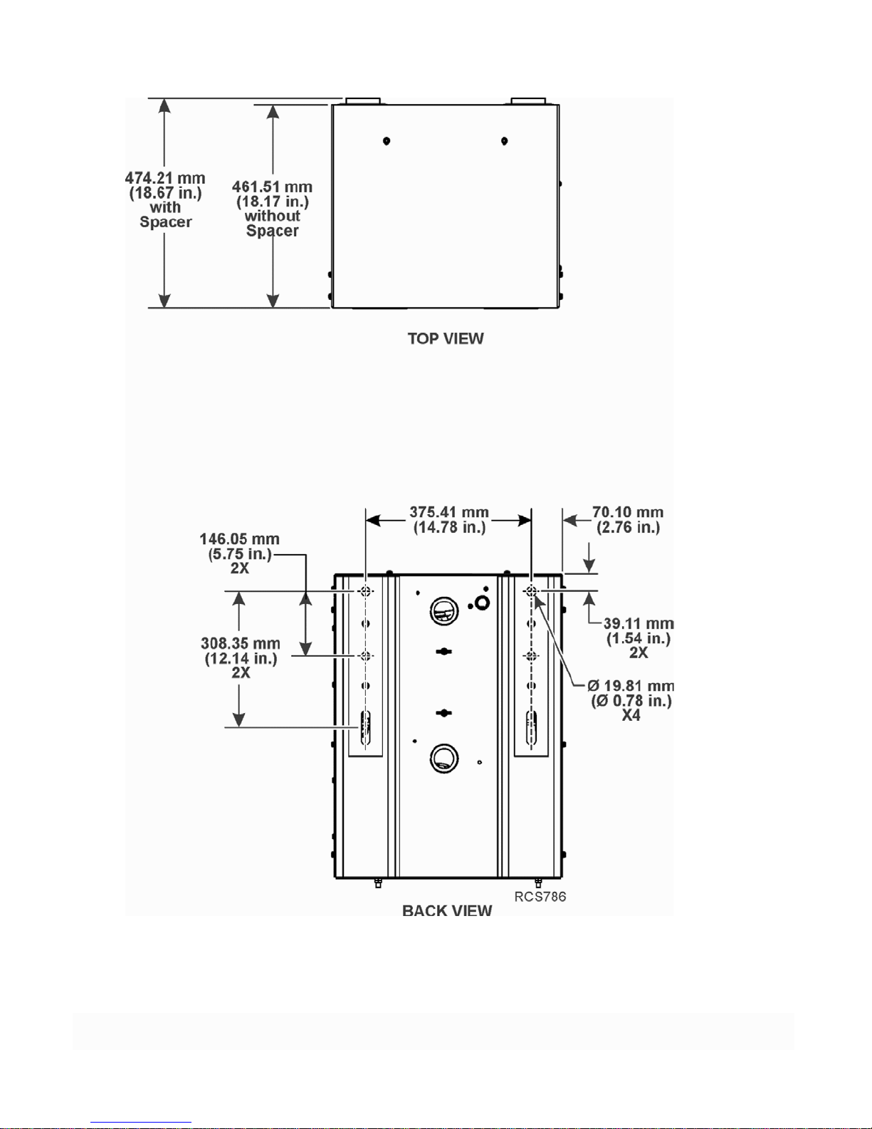
Battery Box Dimensions
Figure 1: Battery Box Dimensions
9
Page 12
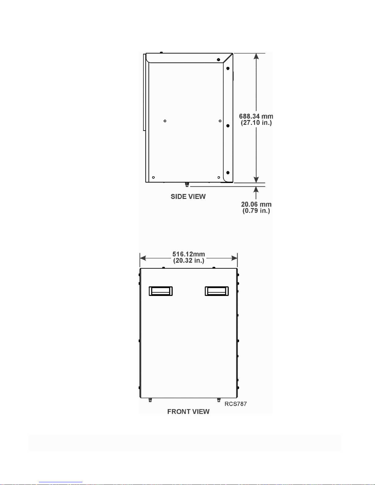
Battery Box Dimensions (continued)
Figure 2: Battery Box Dimensions (continued)
10
Page 13
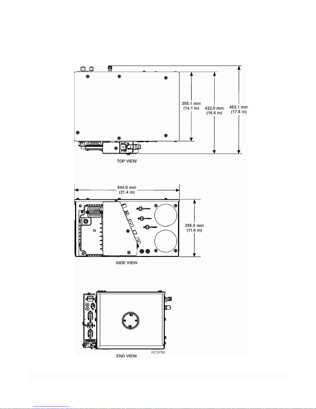
Evaporator/Control Box Dimensions
Figure 3: Evaporator/Control Box Dimensions
11
Page 14
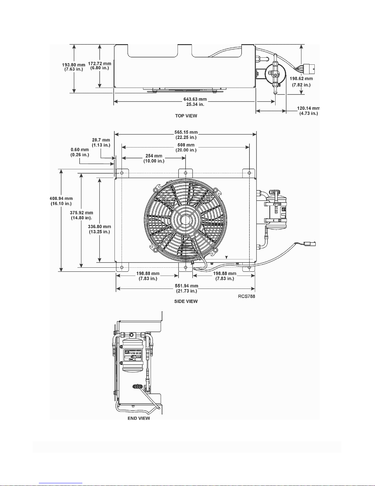
Condenser with Receiver Drier Dimensions
Figure 4: Condenser with Receiver Drier Dimensions
12
Page 15
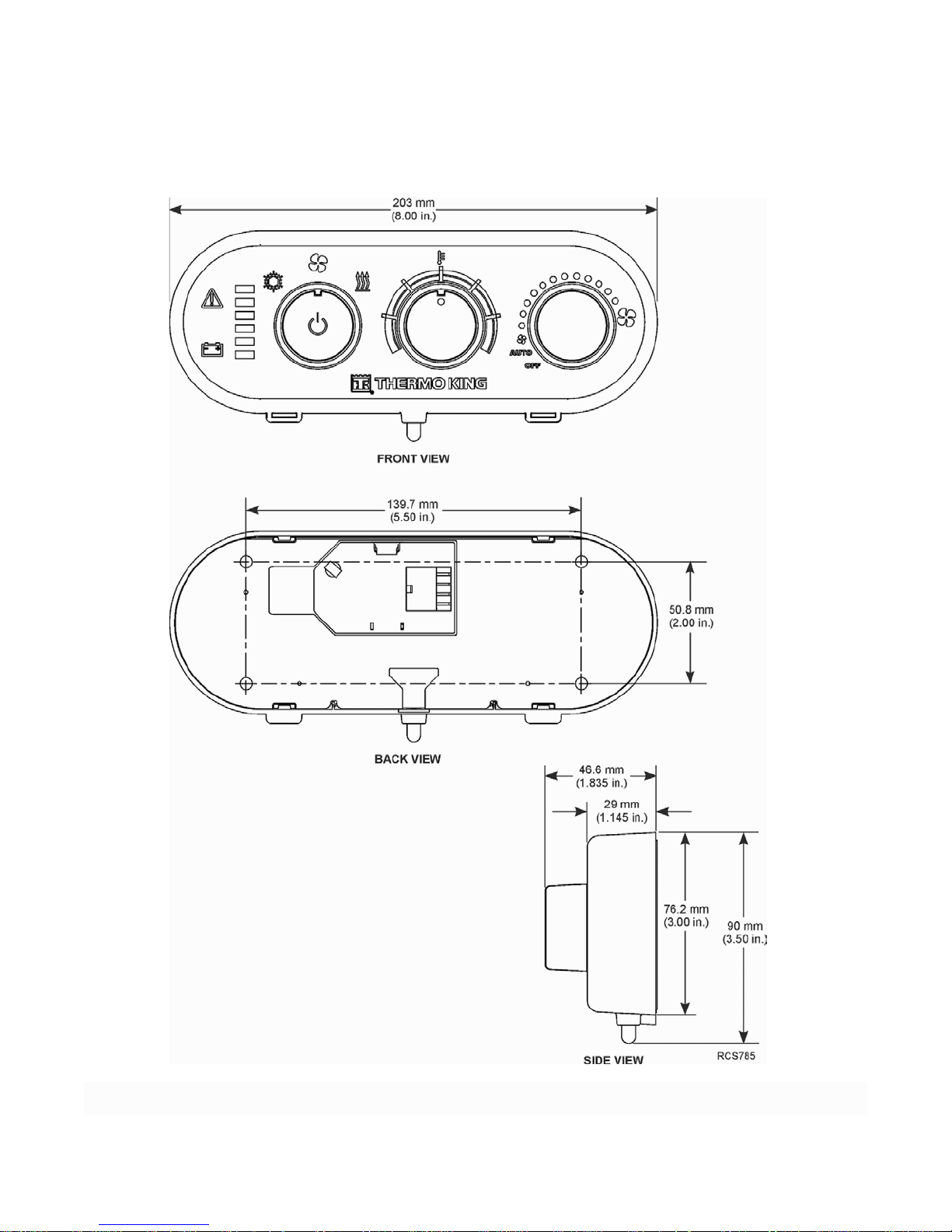
HMI Dimensions
Figure 5: HMI Dimensions
13
Page 16
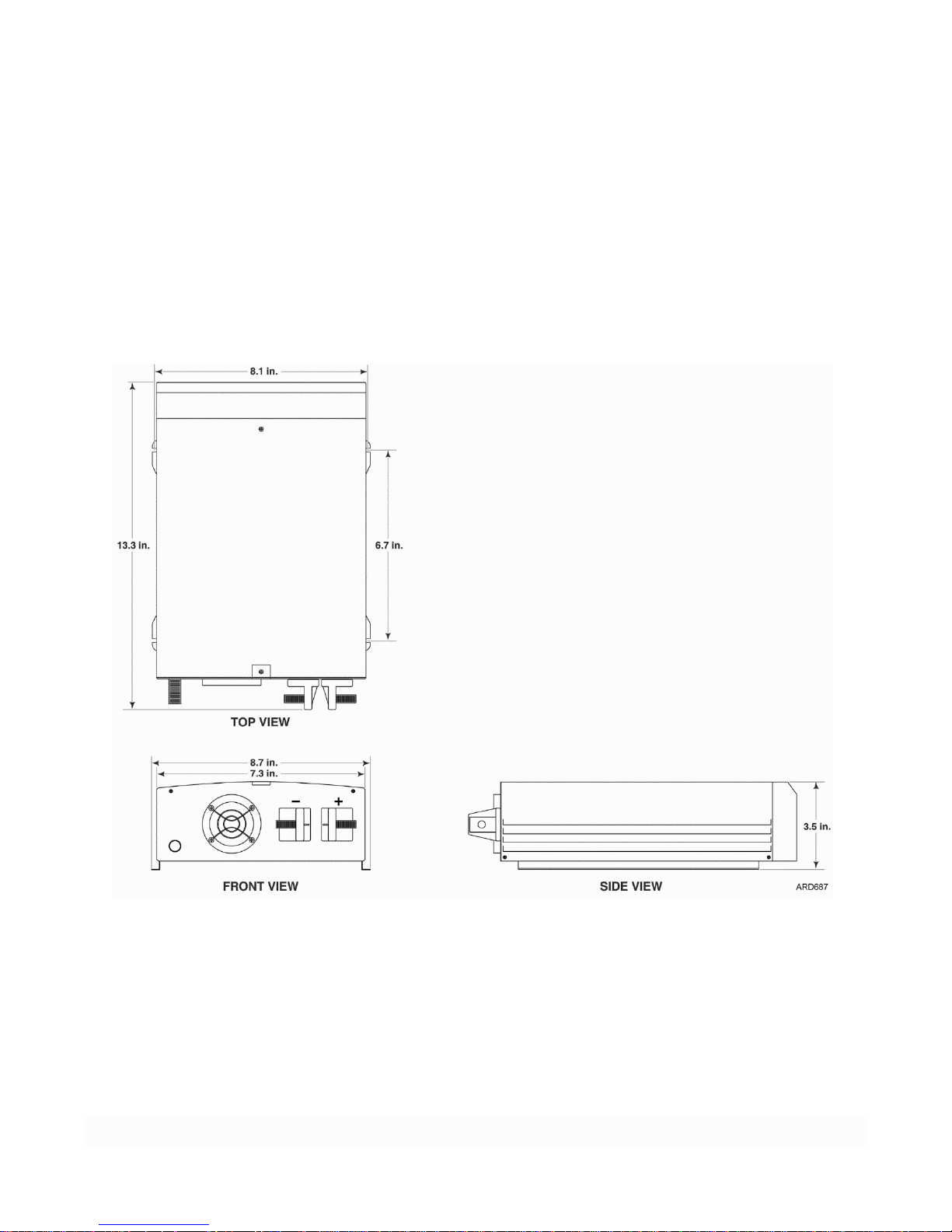
1000 Watt Power Inver ter Dimensions (Option)
Figure 6: 1000 Watt Power Inverter Dimensions
14
Page 17
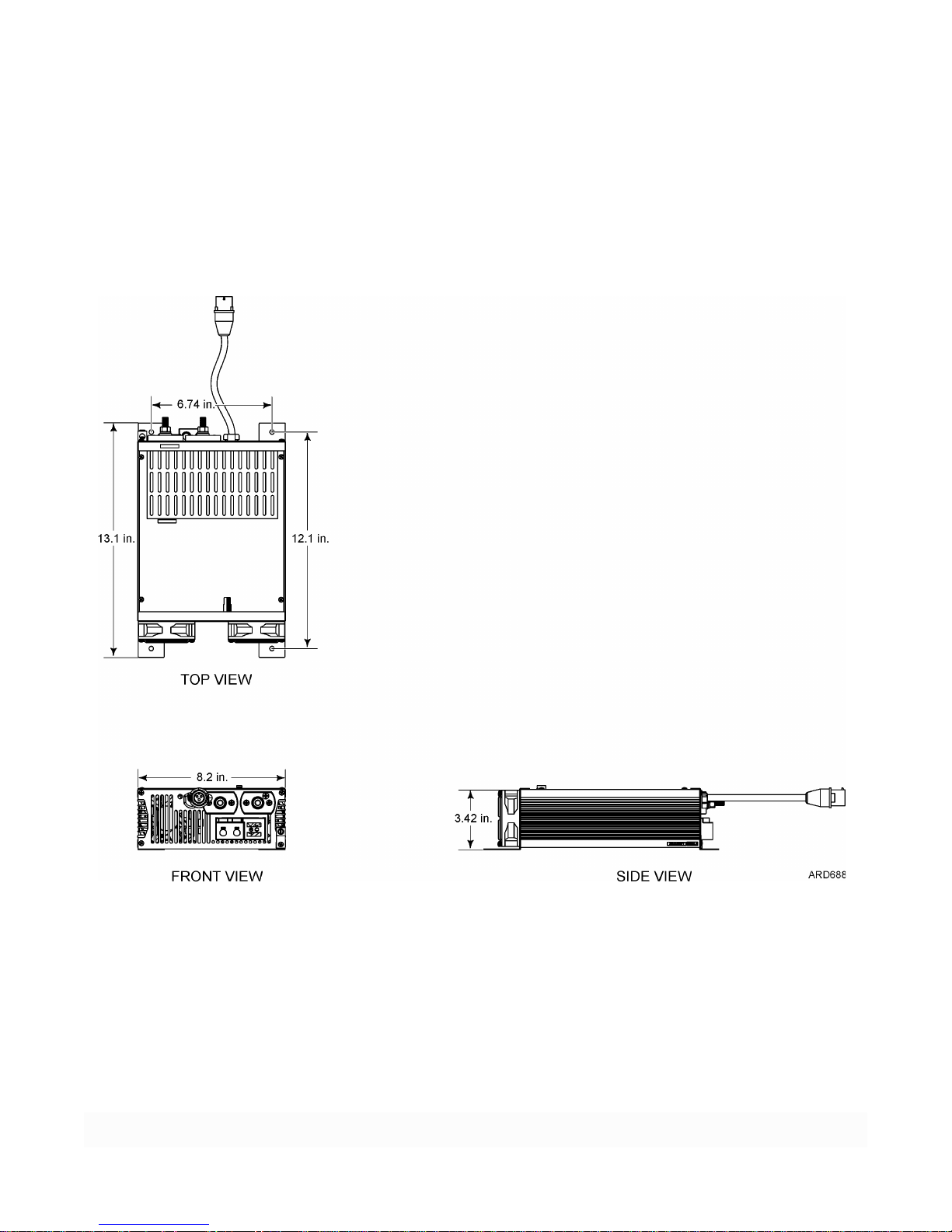
AC/DC Shore Power Converter Dimensions (Option)
Figure 7: AC/DC Shore Power Converter Dimensions
15
Page 18
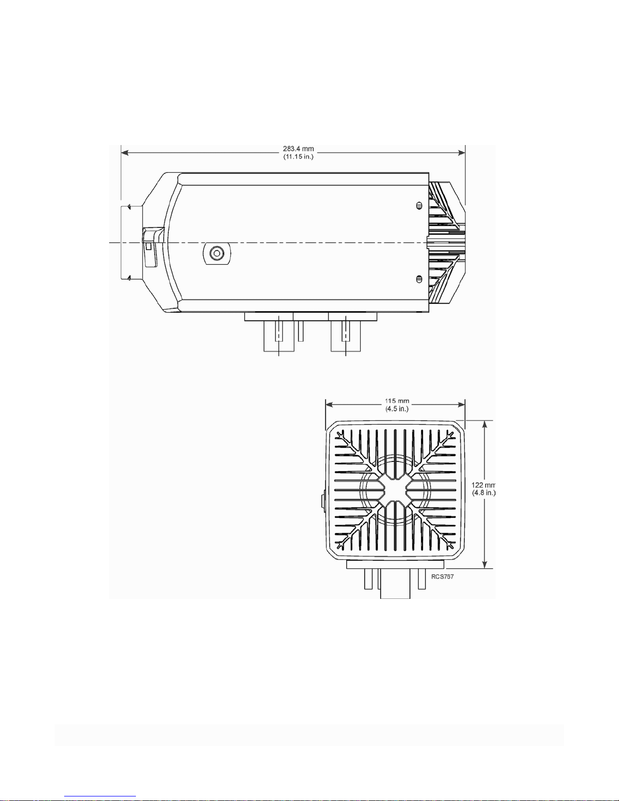
D2/D4 Heater Dimensions (Option)
Figure 8: Heater Dimension
16
Page 19

BLANK PAGE
17
Page 20

Required Tools and Additional Supplies
Tools
1. Typical Mechanics Tools
2. Floor Jack or Motorcycle/ATV Lift
3. Drill Motor
4. Drill Bit Set
5. 7/8" dia. or 1" Step Reamer (for evaporator drain and controller holes)
6. Hole Saws
a. 1" dia. (for fuel tank pickup tube)
b. 2-1/2" dia. (for heater inlet/outlet louver)
c. 2" dia. (access hole for evaporator hoses and elec tric al wiring)
d. 3” dia. ( optiona l si ze acces s hole)
e. 4-1/4" dia. (mounting A/C louver s, r outing A/C d uc ts through and heater mounting hole)
7. Reciprocating Saw (return air opening)
8. 1/2" Wrench
9. Level
10. Tape Measure
11. Utility Knife
12. Caulk Gun
13. Digital Meter (204-1079)
14. Refrigerant Leak Detector (204-712)
15. Hose Fitting Tool (204-1045)
16. Hose Cutting Tool (204-677)
17. Heater Priming Harness (204-1144)
18. Shop Vacuum
19. R-134a Gauge Manifold with automotive connectors
20. Vacuum Pump (204-713)
21. Micron Gauge (204-720)
22. Accurate Refrigerant Scale
23. AGM Battery Tester (204-1959)
24. Heavy Duty AGM Battery Charger (204-1923)
25. Laptop Computer (IBM Compatible) with Microsoft Internet Explorer 10.0 or higher installed.
26. USB Adapter Cable (204-2000)
Supplies (as required)
1. RTV Silicone sealant
2. Sealer Tape (203-391)
3. Alkyl Benzene Refrigerant Oil (670404TKA for lubricating hose fittings and O-rings)
4. Refrigerant 134a
5. Return air wall louver (approximately 11” x 10”)
6. Mounting Clamps #24 and #32 (to secure cables and hoses)
7. Band Wraps (assorted sizes and lengths)
8. Upholstery cleaner
9. Cardboard or blankets (to protect truck interior)
10. Fiberglass repair Kit (only used for fiberglass and wood composite floor)
18
Page 21
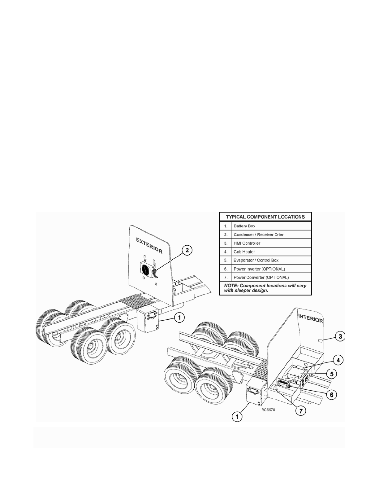
Typical Component Locations
Figure 9: Typical Component Locations
19
Page 22

Tractor and APU Battery Recommendations
Tractor’s Batteries
The tractor’s batteries should not be allowed to become discharged during the APU installation process. Always
connect a battery charger to the tractor’s batteries before beginning the installation.
An alternative method is to shut the tractor’s battery power completely off using the OEM main battery discon nect
switch if available.
For base level performance - tractor battery box must have four 12Vdc batteries connected in parallel to provide 12Vdc
output.
For optimum level performance - Thermo King recommends the tractor batteries be upgraded to Thermo King NXT
1150 CCA absorbed glass mat (AGM) batteries.
NXT AGM Batteries Charge Maintenance
Thermo King NXT AGM batteries are shipped fully charged. Fully charged NXT AGM batteries that are kept in stock
should not require charging for 2 ye ars if ke pt be l ow 77 F (25 C ). NX T AGM batt e ries should be ch a rged w hen th e open
circuit voltage (OCV) falls below 12.50 volts.
To charge the NXT AGM battery, use the following guidelin e s:
1. Verif y the output vo ltage of y our batter y charger is capable of maintaining 14.1 to 14.7 chargin g voltage. The
recommended charging voltage range for the NXT AGM battery is 14.1 to 14.7 volts. Voltages are to be
measured at the battery terminals with the battery connected to the charger.
IMPORTANT: Never exceed 15 volts when charging the NXT AGM battery. Exceeding 15 volts will cause pressure
relief valves to open and out-gas hydrogen and oxygen from inside the battery. This will shorten the life of the
battery and could lead to premature battery failure.
2. Battery chargers with the batte ry type output setting should be set to AGM type battery. Do not set the output
type to gel cell or maintenance free settings.
3. Determine if your battery charger is an automatic or manual charger. Manual battery chargers must be closely
monitored during the charge period and for this reason an automatic battery charger is preferred over a manual
charger.
a. Automatic battery chargers either charge up to a preset voltage and shut off, or charge to a present
voltage and then switch to a trickle charge mode. Either one of these battery chargers is acceptable:
however, the automatic charger that shuts off may not fully charge the battery.
b. Manual battery chargers will have manual controls for setting the charge amperage rate. The charge
amperage rate will remain the same until the battery charger is manually shut off.
NOTE: When using a manual battery charger, set the charger to charge at 10 or 20 amps and limit the charging
time based on the batteries state of charge (SOC). Use the chart below as a general guide to determine the amount of
time necessary to charge the battery. DO NOT overcharge the battery.
20
Page 23

Tractor and APU Battery Recommendations
12.84 Volts
100%
0 Hours
0 Hours
12.50 Volts
75%
2 Hours
1 Hour
12.20 Volts
50%
4 Hours
2 Hours
11.88 Volts
25%
6 Hours
3 Hours
(continued)
Determining Maximum Charge Time Using a Manual Charger
Voltmeter Reading State of Charge Time @ 10 Amps Time @ 20 Amps
WARNING: Overcharging can damage the battery and possibly cause a fire or explosion. Follow the battery
charger’s recommendations for monitoring batteries while charging. Batteries should be monitored while charging
for signs of internal problems. Signs of internal problems include bulging cases, extreme gassing, pungent smell,
and extreme heat. If you notice any of these signs turn the charger off and allow the battery to stabilize before
handling or testing.
Cleaning a Battery
Use a damp cloth to clean the top of the battery to eliminate conductive paths created by dirt and dried or wet
electrolyte, and to prevent corrosion. Use a battery terminal-cleaning tool that has nonco nductive (plastic or r ubber)
cover to clean the battery terminals when corrosion is present. Replace any battery cables (or cable terminals) that are
frayed, corroded, swelled, or damaged to the extent that they cannot be cleaned.
Battery Hold Down Hardware
Batteries are subjected to extreme shock loads and vibration. It is very important to make sure each battery is secured
by the proper mounting hardware. Failure to secure each battery correctly can result in premature battery failure. Using
a torque wrench, torque the hold down nuts in two step increments:
• STEP 1 - Torque ea ch ho ld down nut to 60 in-lbs. (6.8 N•m)
• STEP 2 - Torque each hold down nut to 120 to 144 in-lbs. (13.5 to 16.3 N•m)
Battery Cable Mo un tin g
On threaded stud type batteries, use only stainless steel nuts to fasten the cable to the battery. Torque the nut to 150 to
200 in-lbs. (17 to 22 .5 N•m).
On SAE post type batteries, use o nly stainless steel battery clamp bolts. Torque the nut to 60 in-lbs. (7 N•m).
21
Page 24

Battery Box Installation
Special Tools Required
Modified Floor Jack or Motorcycle/ATV Lift
½” Drive Torque Wrench
STANDARD INSTALLATION METHOD - MOUNTING CLAWS
WARNING: Installer supplie d lifting eyebolts must be forged stee l, 1/2"(12mm) diameter.
WARNING: Use only locking lif ting hooks to attach to the lifting eyeb olts.
WARNING: DO NOT connect any of the TriPac ENVIDIA battery cables to any b atteries at this time.
NOTE: DO NOT OIL THE BOLT THREADS!
1. Remove the cover from the battery box to access and remove hardware that secures box to the shipping crate.
2. It is recommended that a modified floor jack or motorcycle/ATV lift be used to install the battery box.
Protection suc h as c ar db o ard, sho p ra gs, etc. sho uld be us ed und e r t he bo x to pr eve nt d amage d uri ng
installation.
a. Install lifting eyebolts, wa shers and nuts securely into the two holes at the top of the battery box.
b. Using locking lifting hooks, raise the battery box and place onto the lift then remove lifting eyebolts,
washers and nuts.
3. Using a lift, carefully raise the battery box into position. Install the 3/4" bolts and washers through the
mounting claws and the rear of the b attery box.
4. Loosely install the retainers and locking nuts inside the battery box.
NOTE: Mounting bolt threads must extend into the battery box.
IMPORTANT: The following steps are critical and must be followed to ensure the safe installation of the battery box
to the tractor’s frame.
5. With battery box still supported by a lift:
a. Push battery box up tight to tractor’ s frame .
b. Adjust height of box so top and bottom mounting claws and bolts are positioned flat on frame.
c. Review (Detail A) - Lightly tighten mounting hardware only enough to remove excess p lay.
6. Using a torque wrench, torque mounting bolts in four step increments starting with top bolts, then bottom
bolts.
a. STEP 1 - Torque top then bottom mounting bolts to 25 ft-lb. (33.9 N•m). IMPORTANT: STOP and
verify all mounting claws and bolts remained flat on frame (Detail A). If they are not, loosen bolts,
adjust as necessary and retighten again to 25 ft-lb. (33.9 N•m).
b. STEP 2- After first step is s uccessfully completed, tor que top, then bottom bolts to 50 ft-lb. (67.8
N•m).
c. STEP 3- Next, torque top, and then bottom bolts to 100 ft-lb. (135.6 N•m).
d. STEP 4 - Finally, recheck all bolts to confirm they are at 100 ft-lb. (135.6 N•m)
7. Remove the support lift and visuall y inspect installation for the follo wi ng:
a. Mounting claws and bolts are correctly installed. They should be square and flat on the frame (Detail
A).
b. If any mounting claws and bolts are improperly installed on the frame (i/e. they r e semble Details B
& C) - adjust as nec essary.
c. Damaged, deformed or cracked components during installation - must be replace immediately.
WARNING: DO NOT connect any of the TriPac Envidia battery cables to any batteries at this time.
22
Page 25

Battery Box Installation (continued)
STANDARD INSTALLATION METHOD - MOUNTING CLAWS
WARNING: DO NOT connect any of the TriPac Envidia battery cables to any batteries at this time.
NOTE: Mounting bolt threads must extend into the battery box.
Figure 10: Standard Installation Method – Mounting Claws
23
Page 26

Battery Box Installation (continued)
Special Tools Required
Modified Floor Jack or Motorcycle/ATV Lift
Large Drill (appropriate size to drill holes in frame rails)
25/32" or (20 mm) Drill Bit
1/2” or 3/4" Drive Torque Wrench
Direct Mount Bolt Kit (800461)
OPTIONAL INSTALLATI O N METHOD - DIRECT MOUNT
WARNING: Installer supplie d lifting eyebolts must be forged steel, 1/2" (12 mm) diameter.
WARNING: Use only locking lif ting hooks to attach to the lifting eyeb olts.
WARNING: DO NOT connect any of the TriPac ENVIDIA battery cables to any b atteries at this time.
NOTE: DO NOT OIL THE BOLT THREADS!
1. Remove the cover from the battery box to access and remove hardware that secures box to the shipping crate.
2. It is recommended that a modified floor jack or motorcycle/ATV lift be u sed to install the battery box.
Protection such as cardboard, shop rags, etc. should be used under the box to prevent damage during
installation.
a. Install the lifting eyebolts, washers and nuts securely into the two holes at the top of the battery box.
b. Using lock i ng lifting hooks, rai s e the battery box and pl ace onto the l ift then remove the lifting eyebolts,
washers and nuts.
c. The upper batteries must be removed.
NOTE: If the 1 1/2"or 2 ½” spacer options are being used refer to the installation instructions included with the
option kit.
3. DETAIL A - Before installing the battery box to the tractor’s frame, insert the 3/4 x 3.00" long bolts and
washers through the slotted holes at the rear of the battery box.
a. From inside the battery box, install the washers and locking nuts int o the inner frame channe l. Hand
tighten hard war e
b. Position the bolts at the bottom of the slots and tighten to 200 ft-lb. (270 N•m).
4. DETAIL B - IMPORTANT: Observe the positioning of existing OEM fasteners on the tractor’s frame. The
four fasteners used in this Direct -Mount Option need to be located on the tractor’s frame no higher and no
lower than any existin g OEM faste ners.
a. Measure and mark the lo cation of the four mounting holes on the tractor’s frame. Drill four 25/32" (20
mm) holes in the frame.
5. Using the lift, carefully raise the battery box into position and align t he b a tte ry box mounting ho les wit h the
holes in the tractor’s frame.
a. From the backside of the tractor’s frame, insert bolts and washers through the holes in the frame and then
into the battery box.
b. From inside the battery box, instal l the washers and locking nuts into the inner frame channel. Hand
tighten hardware.
6. With the battery box still supp orted by a lift and level with the tractor’s frame, use a torque wrench and torque
the four frame mounting bolts in three step increments as described below:
a. STEP 1 - Torque top then bottom bolts to 50 ft-lb. (68 N•m).
b. STEP 2 - Torque top then bottom bolts to 100 ft-lb. (135 N•m).
c. STEP 3 - Torque top then bottom bolts to 200 ft-lb. (270 N•m).
DO NOT OVER-TORQUE THE MOUNTING BOLTS!
7. Remove the support lift.
24
Page 27

Battery Box Installation (continued)
OPTIONAL INSTALLATI O N METHOD - DIRECT MOUNT
WARNING: DO NOT connect any of the TriPac ENVIDIA b attery cables to any batteries at this time.
Figure 11: Optional Installation Method – Direct Mount
25
Page 28

Condenser and Receiver Drier Installation
Special Tools Required
Hose Fitting Tool (204-1045)
Alkyl Benzene Refrigerant Oil (670404TKA)
Torque Wrench
Fitting Size
Torque Specifications
#6 (3/8”)
11-13 ft-lb (15-17 N•m)
Figure 12: Refrigeration hose I.D. and sizes shown
Sub-Assembly
IMPORTANT: Keep all the A/C fittings capped and sealed until the installa tion of the refrigeration hoses. Refrigerant
oil is extremely hygroscopic and a system left open for more than 5 minutes may require extensive evacuation /
dehydration time to remove moisture.
NOTE: Read and understand Fabricating Refrigeration Hoses on page 30 for proper hose fabrication requirements.
Always use two wrenches while tightening refrigeration fittings.
Hose Cutting Tool (204-677)
Place the condenser coil onto a workbench and subassemble the following components:
• Loosely install the Ambient Temp Sensor
clamp to the receiver drier bracket.
• Install the receiver drier bracket onto the
condenser c oil housing with the Ambient Temp
Sensor clamp to the back. Use supplied 1/4-20
mounting hardware and tighten securely.
• Attach the two large hose clamps to the
bracket.
• Install the receiver drier to the bracket with the
hose clamps and tighten s ecurely. Use arrow to
verify correct direction of refrigerant flow.
• Fabricate and install a #4 hose (5.00 in. long)
with two 90 degree fittings onto the INLET
fitting of the drier and the bottom OUTLET
fitting on the co ndenser coil . Tighten fi ttings to
the torque specs shown.
#8 (1/2”) 15-20 ft-lb (20-27 N•m)
26
Page 29

Condenser and Receiver Drier Installation
Special Tools Required
Template – Condenser Assembly
Tape Measure
Level
Drill Motor
3/8” Drill Bit
Caulk Gun and RTV Silicone Sealant
(continued)
Installation
CAUTION: Before drilling any holes in the trac tor, check for interference with internal wires, supports or interior
panels. Avoid drilling into any interior support members as this could void the tractor’s OEM warranty.
IMPORTANT: Use a backup wrench whenever tightening refrigerant hose fittings.
Locate an area on the exterior of the sleeper to install the condenser assembly that does not interfere with the operation
of existing truck components. The condenser air inlets and fan outlet airflow must not be restricted. Obstr uctions must
not cause recirculation of condenser out air.
If possible, mount the condenser below the bunk level. This allows easier access to 3/8” bolts with large fender washers
inside the sleeper without disturbing interior panels.
1. Measure and mark the exterior center line of the sleeper.
2. Position the supplied template onto the exterior of the sleeper maki ng sure it is level and centered. Ma r k and
drill the 3/8” mounting holes and r emove the template.
3. Apply a bead of RTV silicone around each of the six mounting holes.
4. Install the condenser assembly with the supplied 3/8” stainless mounting hardware.
5. Assure all six mounting tabs a r e in contact with truck body. Use spacers as required.
6. Tighten hardware securely.
27
Page 30

Evaporator/Control Box Installation
Special Tools Required
Template – Evaporator/Control Box
Drill Motor
1/4” Drill Bit
7/8” Step Reamer
2” dia. Hole Saw (standard installation)
3” dia Hole Saw (optional installation)
Reciprocating Saw
Caulk Gun and RTV Silicone Sealant
Sealing Tape (203-391)
Fiberglass C loth a nd Re sin Ki t (if re qu ired)
Figure 13: Evaporator Template shown
PREFERRED LOCATION - FLUSH WITH FRONT BULK HEAD
IMPORTANT: Keep all the A/C fittings capped and sealed until the installa tion of the refrigeration hoses.
Refrigerant oil is extremely hygroscopic and a system left open for more than 5 minutes may require extensive
evacuation/dehydration time to remove moisture.
Maximum cooling is obtained when evaporator inlet is installed flush with the bulkhead. This allows the hot air from
the sleeper to be drawn directly into the return air inlet filter, through the evaporator coil and out the discharge air vents.
Template
The supplied template represent the amount of area needed to accommodate the Evaporator/Control Box and it also
provides the locations for the mounting feet, drain holes and the two 2" access holes. One hole on each side of the
Evaporator/Control Box. If there is not enough room for the hole near the Controller, an optional larger hole can be cut
near the refrigeration hoses. The controller harnesses will wrap around the end of the Evaporator/Control Box.
IMPORTANT ACCESS HOLE INFORMATION:
• The actual location of the 2” access holes will be determined by your particular sleeper construction, including
OEM internal floor supports, electr ic a l wiring, etc.
• Before drilling any holes, check for interference with internal wires, supports or interior panels. Avoid drilling
into the truck’s support membe rs.
• Floors made from fiberglass covered wood construction require the edges of the access holes be completely
sealed with fiberglass and epoxy resin.
• An optional single 3” hole on the refrigerant line side may be used if mounting location does not permit a hole
on the controller side of the Evaporator/Control Box.
28
Page 31

Evaporator/Control Box Installation (continued)
Figure 14: Preferred Location Shown - Flush with Front Bulkhead
NOTE: It is not necessary to remove the Evaporator/Control Box cover to complete a system installation.
NOTE: This installation requires a two -person or mechanically assisted lift.
1. Position template with RETURN AIR flush with bulkhead. Mark location of the 7/8” evaporator drain holes
and 2” access holes. Remove the template:
a. Drill a 1/4” pilot hole for drain holes followed by a 7/8” step reamer.
b. Drill the 2” access holes. The holes may also be located outside the template area as shown.
2. Cut and install a piece of split loo m (or similar) around the inside edge of the 2” access holes to provide
protection for hoses and wiring.
3. Install ret ur n air fil ter s upport to front of Evaporator/Control Box.
4. Set evaporator in place and determine where return air opening needs to be located on bulkhead. Leave
clearance for filter removal.
5. Mark return air opening (11.00 in. x 10.00 in.).
a. Cut opening in bulkhead.
b. A return air grille (installer supplied) can be installed to the bulkhead if desired.
6. Install the defrost drain tubes to the base of the evaporator before mounting to the floor.
7. Loosely install the three mounting tabs onto the evaporator.
8. Secure the evaporator to the floor with TEK screws.
9. Tighten the mounting ta b bolts.
10. From underneath the sleeper:
a. Seal around drain tube access holes with sealing putty or silicone sealant.
b. Apply silicone sealant around the three evaporator mounting screws.
c. Seal any unused holes, cracks, or visible air gaps that might be found.
29
Page 32

Fabricating Refrigeration Hoses
Assembly Materials Checklist
Hose Cutting Tools (204-677)
Nipple Assembly
Alkyl Benzene refrigerant oil (670404TKA)
4.
Nipple with internal O-ring
Figure 15: TK 2000 Components shown
TK 2000 Assembly System
The TK 2000 System is designed for assembly with Multi-Refrigerant hose only.
Hose Fitting Tool (204-1045)
TK 2000 Multi-Refrigerant Hose
Appropriately Sized Clips and Cage
NOTE: The two black O-rings on the nipple assembly are of a specific rubber compound and size. They should not
be removed or replaced.
1. Hose
2. Cage
3. Clips
30
Page 33

Fabricating Refrigeration Hoses (continued)
Cut the Hose
1. Cut the hose to proper length with an appropriate cutting tool. Hand -held hose cutter (204-677) has been
specially designed for cutting all non-wire reinforced hose, such as TK 2000 Multi-Refrigerant hose. Be sure the
cut is made square to the hose length.
Slip on Two Clamps
2. Install one or two proper- size clips, depending on hose size, onto the cut end of the hose. Orientation of the clips
does not affect the performance of the connection. However, for ease of assembly, both clips should have the
same orientation.
CAUTION: Failure to slide the clips over the hose at this time will require the clips to be stretched over the
hose or fitting later. This
may permanently damage the clip.
31
Page 34

Fabricating Refrigeration Hoses (continued)
Oil the Nipple
3. Lubricate the nipple with a generous amount of the Alkyl Benzene refrigerant oil (670404TKA). This MUST be done to
lower the force of nipple insertion.
4. Insert the nipple into the hose. To ensure that the nipple is full y inserted, check the gap between the cut end of the
hose and the shoulder o n the nippl e. Care should be taken to avoid kinking or othe r damage to the hose during
nipple insertion.
NOTE: Be sure to wipe excess oil from the nipple and hose
.
Snap on the Cage
5. Snap the cage into the groove on the nipple. The arms should extend over the hose length. When the cage has been
carefully installed in the cage grove, the cage will be able to rotate in the grove. This step must be performed to
ensure:
a. The clips will be located over the O-ring on the nipp le .
b. The connection will be compatible with the connection’s pressure rating.
Slide the Clips
6. Slide the clips over the cage arms and into the channels on each arm.
Close the Clips
7. Use the fitting tool (204-1045 or 204-1128) to close the clips. The pliers should be positioned squarely on the
clip connection points and should remain square during the closi ng of the clip
NOTE: For easiest assembly, the clasp should be closed between the cage arms.
.
32
Page 35

Fabricating Refrigeration Hoses (continued)
Correct
Incorrect
Nose of the pliers should be firmly seated under the assembly bump and lock latch.
If the pliers are not kept square during closing the clip, the clasp may have an offset. Use the piers to correct the clasp
alignment.
CAUTION: TK 2000 Speedy Clip System components should not be reused. Failure to follow these instructions and/or the
use of TK 2000 Speedy Clip System hose with fittings supplied by other manufactures could result in sudden or
unintended escape of refrigerant gases. Personal injury and/or violations of EPA regulations may occur as a
consequence.
NOTE: Thermo King recommends adherence to all guidelines, including EPA guidelines concerning the service of
refrigerant sy st ems.
33
Page 36

A/C Hose Installation
Special Tools Required
Hose Fitting Tool (204-1045)
Hose Cutting Tool (204-677)
Alkyl Benzene refrigerant oil (670404TKA).
Torque Wrench
Installation
IMPORTANT: Keep all the A/C fittings capped and sealed until the installa tion of the refrigeration hoses.
Refrigerant oil is extremely hygroscopic and a system left open for more than 5 minutes may require extensive
evacuation/dehydration time to remove moisture.
NOTE: The Evaporator/Control Box system has a Nitrogen holding charge of 5 PSI. This holding charge can safely
be vented into the atmosphere.
NOTE: Read and understand Fabricating Refrigeration Hoses section for proper hose fabrication requirements.
IMPORTANT: Always use two wrenches while tightening refrigeration fittings.
Condenser Coil to Evaporator/Control Box (Discharge Line)
1. Fabricate a #6 hose with a 90 degree fitting and connect to the fitting on the condenser coil inlet (top
connection). Tighten the fitting to 15-20 ft-lb (20-27 N•m). Use a backup wrench.
2. Route the ho s e up throu gh the 2” access hole in the tractor floor near the Evaporator/Control Box air
conditioning fittings.
3. Cut the hose to length, install a 90 degree fitting with service por t a nd a tta c h it to the large fitting o n the
Evaporator/Control Box. Tighten the fitting to 15 to 20 ft-lb (20 to 27 N•m). Use a backup wrench.
Receiver Drier to Evaporator/Control Box (Liquid Line)
4. Fabricate a #4 hose with a 90 degree fitting and attach onto the receiver liquid line outlet fitting on the
receiver drier. Tighten the fitting to 11 to 13 ft-lb (15 to 17 N•m). Use a backup wrench.
5. Route the hose up through the 2” access hole in the tractor floor near the Evaporator/Control Box air
conditioning fittings.
6. Cut the hose to length, install a 90 degree fitting and attach onto the small fitting on the Evaporator/Control
Box. Tighten the fitting to 11 to 13 ft-lb (15 to 17 N•m).
7. Secure all hoses adequately with clamps or band wraps.
34
Page 37

A/C Hose Installation (continued)
#4 Liquid Line from Drier Outlet
#6 Discharge Line from Condenser
Figure 16:A/C Hose I.D. and routing sh o wn
35
Page 38

A/C System Evacuation and L eak Check Procedures
Special Tools Required
Vacuum Pump (204-713 or equivalent)
Micron Gauge (204-720)
Refrigerant Leak Detector (204-712)
Gauge Set with R134a Adapters
System Evacuation Procedures
IMPORTANT: Always use recommended vacuum equipment. Before each use, check that there are no leaks in the
vacuum equipment e it he r in the pump itself or in the ho se s. The oil in the evacuation sta t ion vacuum pump sho ul d
be changed after each use.
NOTE: While the system is being ev acuated, continue the installation with D2/D4 Heater if applicable.
1. Connect gauge manifold to suction and discharge service ports at the Evaporator/Control Box.
2. Connect service line of the gauge manifold to vacuum pump and micron gauge.
3. Open gauge manifold and vacuum p ump valves and gauge manifold hand valves.
4. Start vacuum pump and evacuate until system reaches 500 microns.
5. Once syste m reaches 500 microns, continue e vacuation for one additional hour.
6. Close vacuum pump isolation valve, switch off pump. Chec k that the gauge reading for the system does not
exceed 2000 microns in the following five minutes. If vacuum level exceeds 2000 microns before five
minutes, and continues to rise, proceed to the Leak Check Procedures section. If it stops in a vacuum
continue to evacuate for an additional 30 minutes.
7. If vacuum level remains below 2000 microns for 5 mi nutes the system is leak free and ready to be filled with
refrigerant.
8. Close mani fold hand valves and remove evacua tion equipment.
Leak Check Procedure
1. Add vapor R-134a to the unit until bottle pressure is reached.
2. Thoroughly leak check the system with an electronic leak detector.
3. If leak(s) are found, recover leak check charge.
4. Repair any leaks and re-evacuate system.
36
Page 39

D2/D4 Heater Installation (Heat Optio n)
Special Tools Required
Drill Motor
Utility Knife
Center Punch
4-1/4” dia. Hole Saw
Fiberglass Cloth and Resin Kit (if required)
Figure 17: Marking and Cutting the Hole.
Heater Location
IMPORTANT: Correct installa tion of this heater is necessary to ensure safe and proper operation.
BEFORE installing the heater, thoroug hly re ad and understand the heater manufacturer’s manual included with
the heater.
The location for mounting the heater will vary depending on the type of tractor. Typically, the heater is mounted inside
the sleeper, under the bunk in a storage compartment. However, the heater may be mounted anywhere inside the tractor
provided you adhere to the following conditions:
• Install heater so it will maintain a mini mum distance of 2.00 inches (50.8 mm) from any heat sensitive or
flammable material.
• Combustion air intake, exhaus t a nd fuel inlet must be located outside the tra c tor.
• Install exhaust hose so it will maintain a minimum d istance of 2.00 inches (50.8 mm) fr om any hea t sensitive
or flammable material.
• Heater must be mounted on flat horizontal surface providing an air tight seal between heater and tractor.
• All floor matting, carpet, insulation, etc. must be removed to allow the heater to be mounted directly to the
bare floor.
• Heater harness may be repos itio ned to ei the r side of the heat er.
• Floors made of fiberglass covered wood construction require the edges of the access hole be sealed with
fiberglass and epoxy resin.
Drilling Hole in Floor
1. Position the heater’s metal
mounting plate onto the
floor mat.
2. Use a utility knife to cut the
floor mat around the outside
edges of the plate. Remove
floor mat to access the bare
floor.
3. With the mounting plate in
position, center punch the
four outer holes. Re move
the mounting plate and
mark an “X” c onnecting the
four center punched o ut er
holes.
4. Center punch the center of
the “X” and drill a 4-1/4”
hole with a hole saw.
37
Page 40

D2/D4 Heater Installation (continued)
Figure 18: Heater Subassembly and Installation.
Heater Subassembly
Turn the heater upside down and att ach the following co mponents:
1. Snap the air outlet hood onto the end of the heater.
2. Place the mounting plate onto the heater studs. Mounting hardware will be installed later.
3. Attach the short rubber hose and clamps onto the fuel inlet connection located at the base of the heater.
4. Insert the plastic fuel line all the way into the rubber hose until it bottoms o ut to prevent air gaps. Tighten both
hose clamps securely.
5. Attach the exhaust hose and metal clamp onto the fitting located under the OUTLET end of the heater. Turn
metal clamp to the center and tighten securely.
6. Insert the plastic air intake tube through the beveled opening of the small plastic mounting plate. Install the
plastic plate and tube onto studs located under the INLET end of the heater.
7. Install lock washers and nuts onto each of the mounting studs and tighten hardware securely.
8. Install gasket to mounting plat e .
9. The heater has two service data nameplates. Remove one a nd reinstall it onto the top of the heater so that it is
visible when the heater is installed.
Heater Installation
10. Position the heater over t he access hole with intake and exhaust hose and fuel line exiting t he tractor. Attach
the heater to the floor with TEK screws and tighten securely.
NOTE: Tighten TEK screws sufficiently to ensure a positive seal be tween mounting plate and mounting surface. Do
not over tighten!
38
Page 41

D2/D4 Heater Installation (continued)
Figure 19: Exhaust and Combustion Air Intake Routing
Exhaust and Combustion Air Intake Routing
IMPORTANT: Correct installa tion of this heater is necessary to ensure safe and proper operation.
BEFORE installing the heater, thoroughly read and understand the heater manufacturer’ s manual included with
the heater.
DANGER: The correct installation of the exhaust and combustion air intake hoses is extremely important to prevent
carbon monoxide poisoning or asphyxiation.
EXTREME CARE MUST BE TAKEN TO:
• Route the exhaust outlet hose and combustion air intake tube so they cannot be plugged by d ir t, water or snow.
• Ensure the exhaust outlet and air inlet d o not face into the tractor’s slip stream to prevent “ram air” effect.
• Keep exhaust outlet and air intake hoses a minimum of 12” apart.
• Install exhaust hose so it will mai ntain a minimum distance of 2.00 inches (50.8 mm) from any heat sensitive
or flammable material.
• The exhaust hose should be mounted slightly downwards to help drain off condensation.
• Install the protective cap onto the end of the exhaust hose.
• Route the exhaust hose to an open area to the rear or side of the tractor so fumes cannot build up and enter the
cab or the combustion air inlet tube to the heater.
• DO NOT mount the exhaust hose to the tra c tor’s frame. It must be installed to the cab to a llow for movement.
Installation
DANGER: The exhaust hose outlet must exit at least 3 feet from the A/C evaporator drains located under the tractor
to prevent carbon monoxide poisoning or asphyxiation.
ALWAYS VERIFY the two water valves (kaz oos) ar e inst al led on to t h e evapor at or dr ain tube s and are secured with
hose.
1. Route the ex haust hose to an open area to the rear or side of the tractor positioned slightly downwards to help
drain off condensation and secure with clamps .
a. Drill a 1/8” hole in exhaust hose if necessary to allow for water dra inage.
b. Exhaust hos e can be shortened to a minimum of 8” if required.
2. Attach metal end cap to exhaust hose.
3. Position air intake tube
facing towards the rear of
the tractor where it can
pick up clean, fresh,
moisture free air.
4. From underneath the
sleeper:
a. Apply silicone
sealant around
ONLY the four
heater mount in g
screws.
b. DO NOT apply
any sealant
around the access
hole!
39
Page 42

D2/D4 Heater Duct Installation (Heat Opti o n)
Special Tools Required
Drill Motor
2-1/2” Hole Saw (for installing discharge return air vents)
3” dia. Hole Saw (for routing ducts through compartment walls if required)
Duct Locations
CAUTION:
• USE SUPPLIED HEATER DUCT H OSE ONLY! D o not use existing v ehicle ducts or o utlets.
Ducts and outlets must be capable of withstanding a minimum of 300F (148.9C) operating
temperatures.
• Adjustable air vent must alway s b e insta lle d so it cannot blow hot air directly at liv ing creatures (people,
animals) or objects sensitive to temperature.
• Do not position outlet so that it will blow hot air directly at operator o r at thermostat.
• Position air outlet so that it cannot be obstructed.
• Use the supplied protective air intake grille on the air inlet side of the he ater to prevent objects from being
sucked in.
• Do not overtighten duct clamps.
• DO NOT lay or bundle the heater ducts with A/C ducts. They should not touch each other.
• Ensure provisions are mad e for proper air return v entilation.
The heater is equipped with a Return Inlet and Discharge Outlet for attaching the flexible heater duct hoses.
IMPORTANT: A return air duct to the heater should be provided for best heating efficiency.
• Return Inlet must be provided to return air to the heater. It is typically mounted at the base of the bunk
directly opposite the discharge outlet ve nt.
• Discharge Outlet should be located at floor level to provide maximum heating comfort in the sleeper. It is
typically installed at the base of the bunk on one end.
• Heater ducts should be installed and routed with smooth bends and no kinks to provide maximum airflow.
Installation
40
Page 43

D2/D4 Heater Duct Installation (continued)
Figure 20: Discharge and Return Air Duct Installation
Discharge Air
1. Find an appropriate locatio n f or the floor level discharge air vent and drill a 2-1/2” hole using the correct
hole saw.
a. Unsnap rotating outer louver assembly from the mounting base.
b. Install the base into 2-1/2” hole and secure with supplied screws.
c. Reinstall rotating outer louver assembly back into the mounting base ring. Verify that it rotates freely.
2. Attach one end of the heater duct to the dischar ge outlet hood on the heater and secure with supplied clamp.
3. Route the heater duct to the floor level discharge air vent, cut as needed, attach to the end of the plastic louver
vent and secure with sup plied hose c lamp.
Return Air
4. If a return air duct is not used, the protective grille must be installed onto the heater inlet.
5. Find an appropriate locatio n f or the floor level return air grille and drill a 2-1/2” hole usi ng the correct hole
saw.
a. Install the return air grille into the 2 -1/2” hole and secure with supplied screws.
6. Attach one end of the return air duct to the air inlet hood on the heater and secure with supplied clamp.
a. Route the return air duct to the return air grille, cut as needed, attach to the end of the plastic
louver vent and secure with supplied hose clamp.
41
Page 44

A/C Duct Instal lation
Special Tools Required
Drill Motor
vents and routing ducts through compartment walls)
A/C Vent Locations
The evaporator is equipped with two air discharge outlets to a tta c h the supplied flexible air ducts. The ducts will be
attached to plastic air vents that should be located and installed to provide maximum air circulation in the sleeper.
Suggested locations of the ai r vents:
• MEDIUM (above lower bunk level)
• HIGH (above upper bu nk level)
A/C air ducts and vents are typically routed and installed through closets or storage compartments. Route air ducts as
directly as possible with fewest number bends. Stretch out air ducts and cut off loose excess duct material. Verify all
duct connections are leak free.
In some applications one of the Envidia air ducts may be connected to the truck OEM ducts. If this is done, a backflow
damper must be installed in the duct near the truck’s under bunk OEM A/C unit. A back flow damper kit is provided
along with installation instructions.
NOTE: When connecting to OEM duct work a backflow damper must be installed. This will prevent air from back
flowing into the OEM HVAC ho using . Reduced maximum system runtime will result if damper is not installed.
NOTE: The A/C air duct adapter plate can be installed on either side of the Evaporator/Control Box. Optional
adapters will allow one duct on each side.
IMPORTANT: Ex t reme care shou l d always be taken when drilling holes in the various types of material found in
sleepers such as plastic, steel, a luminum, and upholstery.
Installation
4-1/4” dia. Hole Saw (for installing plastic A/C louver
1. Install the hose adapters into each air discharge outlet plate.
2. Find appropriate locations for the A/C vent(s) inside the sleeper and drill 4-1/4” diameter hole(s).
3. Attach the flexible air duct onto hose adapter(s) and secure with a supplied hose clamp.
4. Route the flexible air duct thro ugh the A/C ve nt hole. Cut excess duc t as needed .
5. Unsnap rotating outer louver assembly from the mounting base.
6. Attach to flexible air duct to the end of the hose adapter with band wraps.
7. Push the hose adapter back into 4-1/4” mounting hole and secure with supplied screws.
8. Reinstall rotating outer louver assembly back into the hose adapter and verify that it rotates freely.
9. Verify flexible ducts are installed and routed with smooth bends and no kinks to provide maximum airflow.
10. Secure flexible ducts with large band wraps to prevent excess movement.
42
Page 45

A/C Duct Instal lation (continued)
Figure 21: A/C Duct locations
FLUSH MOUNTED EVAPORATOR
43
Page 46

Battery Box Harness Ins tallation
Figure 22: Battery Box Harness Connections
From Envidia
Through
Controller
IMPORTANT: Before making any electrical connections, confirm the battery cables in the TriPac Envidia battery
box and truck battery box are not connected to the batteries.
NOTE: Excessive communication harness length should be doubled up and secured with band wraps. DO NOT
CUT THE WIRE H ARNESS!
NOTE: Always check the male pins for straightness before attempting to mate connectors. If any resista nc e is f e lt
when mating the connector: recheck the male pin alignment. Exercise care when mating the connections to circuit
boards.
From TriPac ENVIDIA Battery Box
1. From the TriPac Envidia Battery Box route the Base Controller Communication harness and white (8 AWG)
power wires through the floor access hole. Route to the Evaporator/Control Box Connector Panel.
2. The Battery Box communication harness plugs into the 12-pin, (J8) connector on the Connector Panel.
3. Remove the Interconnect Harness cover plate.
4. Insert grommets into the two hol e s i n the Con ne c to r P a ne l .
5. Route the Ba se Co ntroller power wires through the holes in the Connector P a nel to the Base Controller.
6. Cut cables to length. Terminate with ¼” terminal lugs.
7. Connect the #2 power terminal lug to the stud marked +2. Co nnect the CH-0 1 ground te rminal lug to the stud
marked CH. Tighten the nuts to 1 8 in-lbs. (2.0 N•m).
IMPORTANT: Make sure the two terminal lugs are not touching each other!
8. Reinstall the Interconnect Harness cover plate.
9. Route the RED and BLA CK (2 AWG) cables from the TriPac ENVIDIA battery box to the truck battery box.
Do not connect at this time.
Battery Box
Connector Panel to
44
Page 47

Battery Box Harness Ins tallation (continued)
Figure 23: Battery Box harness connections
From Evaporator/Control Box
10. From the Evaporator/Control Box route the RED and BLACK (4 AWG) Co mpressor Drive Module power
cables through the floor access hole with the refrigerant lines. Route cables to the back of the TriPac Envidia
Battery Box. NOTE: These cables are pre-connected to the Compressor Drive Module inside the
Evaporator/Control Box.
11. Route the posi t ive cable (RED) through the upper hole in the back of the battery box to the F10 (150 amp) fuse
in the holder.
12. Cut cable to length and install terminal with 1/4” hole.
13. Connect to F10 fuse holder terminal. Torque nut to 120 in-lb (13.5 N•m).
14. Route the negat ive (BLACK) cable through the lower hole in the back of the battery box to the chassis ground
stud.
15. Cut cable to length and install terminal with 3/8 ” ho le .
16. Secure to existing cables.
17. Connect to chassis ground stud.
45
Page 48

Condenser Fan and Sensor Harness Installation
Figure 24: Condenser and Sensor Harness Connections
IMPORTANT: Before making any electrical connections, confirm the battery cables in the TriPac Envidia battery
box and truck battery box are not connected to the batteries.
NOTE: Excessive harnesses lengths should be doubled up and secured with band wraps. DO NOT CUT THE WIRE
HARNESSES!
NOTE: Always check the male pins for straightness before attempting to mate connectors. If any resista nc e is f e lt
when mating the connector: recheck the male pin alignment. Exercise care when mating the connections to
Connector Panel.
Evaporator/Control Box
1. Locate the Condenser Fan and Sensor harness supplied loose in the installation kit.
2. Locate the Connector Panel located outside the Evaporator/Control Box.
3. Connect the 6-pin connector to the Condenser (J6) connector.
4. Route the harness down through the 2” access hole in the tractor floor and out to the condenser fan.
Condenser Assembly
5. Connect the 4-pin connector to the matting connector from the condenser fan.
6. Attach the Ambient Air Sensor to the inside of the receiver drier bracket with the supplied clamp and
mounting hardware.
NOTE: Always install the sen sor to the inside of the drier bra cket for best temperature readings and to pro te c t it
from damage.
7. Secure all harness adeq uately with insulated cla mp s or band wrap s.
46
Page 49

Ignition Switch and Harness Installation
Figure 25: Ignition Switch Harness Connections
IMPORTANT: Th e Ignition Sense h arness wire must be connec t ed to the ON or RUN position of t h e tractor’s
ignition system. This will prev e nt the HVAC system from operating and allow battery charging when the tractor’s
engine is running.
Locate the Ignition Sense harness supplied loose in the installation kit.
1. Connect the 2-pin connector to the I gnition (J10) connector on the Evaporator/Control Box connector panel.
2. Route the harness towards the tr a c tor’s ignition switch.
3. Connect the end with the diode and fuse to the ON or RUN position of the tractor’s ignition switch.
4. Secure the harness adequately with band wraps.
NOTE: On some truck models the ignition switch acts only as a selector device connected to an ignition module. There
may not be system power available at the switch. The TriPac Envidia sys tem may not function correctly. In this case
locate the truck ignition module and connect to the ON or RUN outpu
t.
47
Page 50

HMI Installation
Special Tools Required
Level
Drill Motor
Drill Bits
Figure 26: HMI Controller Installation
HMI Controller Location
Choose a location inside the tractor’s sleeper for the HMI controller that is easily accessible and visible from
the driver’s bunk
Installation
Locate the HMI Controller Harness with the 8-pin conne c tors on each end supplied loose in the installation kit. The
connectors are not the same. Connect the white end to the HMI.
1. Route the harness to the Evaporator/Control Box.
2. Connect the black 8-pin connector to the HMI (J7) connector on the Evaporator/Control Box connector panel.
3. From the Evaporator/Control Box , route th e harness behind the in terior walls (if applicable) to the location chosen
to install the HMI controller.
4. Unsnap the r ear mounti ng base from the controller and route the harness connector through the access hole.
a. Positio n and le vel the mo un ting base a nd i ns ta l l s e c ur e l y.
5. Push the white connector firmly into the plug on the rear of the controller.
6. Snap the controller back onto the mounting base.
7. Secure harness.
48
Page 51

USB Service Communi catio n C ab l e
Figure 27: USB Cable Connection
The USB Service Communication Cable will allow installation and service technicians to ea sily access the
communication application.
1. On the Base Controller, remove the cover over the USB Communication Port.
2. Plug the USB Mini-B connector into the communicatio n port.
3. Route the cable to a protected area that is accessible without raising the bunk. Recommend inside truck tool
box door.
4. Secure communication cable to other harnesses or cab structure.
49
Page 52

D2/D4 Heater Harness Installation (Heat Option)
Figure 28: D2/D4 Heater Harness Connection
Locate the Heater Harness supplied loose in the installation kit. Remove the two small plastic bags attached to the
harness cont aining the fuel pump electrical connector components and the in-line fuse assembly. Retain these for
installation later.
1. Connect the 14-pin connector (with the locking tab) to the mating connector on the heater.
a. Use a large bladed screwdriver to pull the locking tab out (to unlock) from the connector body.
b. Connect the two connectors together.
c. Push locking tab back in (to lock) the connector body.
2. Connect the 10-pin connector to the Heater (J9) connector o n t he Evaporator/Control Box connector panel.
3. Route the fuel pump harness out of the sleeper through the 2” access hole. It will be assembled and connected
to the fuel pump in a later step.
NOTE: The Diagnostic Connector near the heater is only used for diagnostic purposes.
50
Page 53

Heater Fuel Pickup Tube Installation (Heat Option)
Special Tools Required
Tape Measure
Tubing Cutter
Direct Tank Installation – No Drilling
OEM Fuel Tank Fittings
DANGER: Use caution when working in or around the area of the diesel fuel tank. Diesel fuel vapors are potentially
explosive. Do not smoke while working near the diesel fuel tank.
NOTE: Some fuel tanks may have auxiliary fuel connections or 1/4" NPT connections factory installed . These
fitting eliminate the need to drill into the f ue l tank to install the heater’s fuel pickup tube.
• OEM Fuel Connections - Route and connect the heater’s fue l sup ply line to one of these fittings.
• OEM 1/4" NPT Fitting - See following installation instructions.
Important Installation Tips
• Remove the protective cap from the e nd of the pickup tube prior to installatio n.
• Do not apply any type of sealant material to the fuel pickup tube assembly. Doing so will result in plu gged fuel
lines.
Installation
NOTE: The tank mounted fuel pump bracket cannot be used on direct tank installations. The supplied
remote mounted L-bracket must be used.
1. Remove the nut, washers and b us hing assembly from the fuel pic kup tube as shown. The nut, washers and
bushing assembly will not be used.
2. Remove the 1/4" NPT fitting from fuel pickup tube and install it into the fuel tank’s 1/4" NPT fitting securely.
3. Measure the fuel tank diameter and cut the pickup tube 3” shorter.
4. Install the pickup tube with the fer rule nut into the tank.
a. Position the pickup tube as needed to facilitate fuel line connections and tighten ferrule nut securely.
5. Install the supplied warning n ameplate onto the fuel tank in a visible area near the fuel cap.
51
Page 54

Heater Fuel Pickup Tube Installation (continued)
Figure 29: Fuel Pickup Tube Installation – No Drilling
Direct Tank Installation – No Drilling
52
Page 55

Heater Fuel Pickup Tube Installation (continued)
Special Tools Required
Tape Measure
Drill Motor
¼” Drill Bit
1” Hole Saw
Tubing Cutter
Alternative Instal la t ion – Drilling hole in Fuel Tank
Installing the Fuel Pickup Tube
DANGER: Use caution when working in or around the area of the diesel fuel tank. Diesel fuel vapors are potentially
explosive. Do not smoke while working near the diesel fuel tank.
DANGER: Before drilling into a fuel tank, drain all fuel from the tank. Use nitrogen or an inert gas to purge the
diesel fuel vapors from the tank. Keep the diesel tank filled with inert gas while drilli ng.
DANGER: Use extreme ca ution when drilling into a diesel fuel tank . Sparks from an electric drill or drill bit could
cause an explosion.
Important Installation Tips
• Check for i nt ernal baffles inside the fuel tank BEFORE drilling any holes.
• Remove protective caps from ends of pic kup tube prior to installation.
• Do not apply any type of sealant material to the fuel pickup tube assembly. Doing so will result i n plugged f uel
lines.
• The ferrule nut and 1/4" NPT fitting must be tightened securely into the bushing before installing the pickup
tube into the tank. Failure to tighten the fittings will allow the bushing and washer assembly to slide down the
pickup tube and drop into the fuel tank.
Installation
1. Measur e a nd ma rk the mo u nt i n g h o l es o n t he fu e l ta n k as sho wn.
2. Drill (2) 0.25" outer holes first followed by the 1.00" center hole.
a. Thoroughly cle an a nd flus h the tank t o remove any chips.
3. Measure the fuel tank diameter and cut the pickup tube 3” shorter.
a. With the pickup tube positioned at the correct height, place a wrench on the flats of the bushing and
tighten the 1/4" NPT fitting and the ferrule nut securely.
4. Remove the large nut, metal cupped washer and rubber washer from the bushing assembly.
a. Insert the fuel pickup tube (with the reinforcing washer) into the tank using the slot created by the two
0.25" holes.
b. Lift the pickup tube and bushing into positio n through the 1.00" ho le.
c. Hold the pickup tube in place and reinstall the rubber washer, metal cupped washer, fuel pump
bracket and large nut ont o the bushing. Hand tighten the large nut.
d. Position the pickup tube as needed to facilitate fuel line connections.
e. Place a wrench on the flats of the bushing and tighten the large nut securely.
5. Install the supplied warning nameplate onto the fuel tank in a visible area near the fuel cap.
53
Page 56

Heater Fuel Pickup Tube Installation (continued)
IMPORTANT: The ferrule nut and 1/4" NPT fitting must be tightened securely into the bushing before
Figure 30: Fuel Pickup Tube Installation – Drilling Hole in Tank
Alternative Installation – Drilling hole in Fuel Ta nk
installing the pickup tube into the tank.
54
Page 57

Heater Fuel Pump and Fuel Line Installation
Special Tools Required
Utility Knife
Hose Cutting Tool (204-677)
(Heat Option)
Tank Mounted Fuel Pump
1. Install the fuel pump and rubber clamp onto t he tank mounted bracket securel y.
2. Attach a fuel line hose from the fuel pick-up supply to the inlet end of the fuel pump and secure with supplied
hose clamps.
3. Attach the short rubb er hose connection to the outlet end of the fuel pump and secure with supplied hose
clamps.
4. Route the plastic fuel line (installed earlier on the heater) to the fuel pump and cut to length. Insert the fuel line
into the rubber hose connection until it butts up tight with the fuel pump’s outlet pipe. Secure with supplied
hose clamp.
NOTE: The fuel line must be installed c orrectly to prevent air bubbles (DETAIL A).
The fuel line from the pickup tube, to fuel pump, to heater should be routed at a continuous rise.
CAUTION: Only use a hose cutter o r utility knife to cut plastic fuel lines. Do not use a wire cutter as this will pinch the
plastic fuel line closed.
Remote Mounted Fuel Pump with L-Bracket
Choose a protected lo ca tion under t h e cab close to the f uel pick-up tube and heater and install the supplied L-bracket
securely with TEK screws.
1. Install the fuel pump into the rub ber mounting clamp and t hen onto the L-bracket.
2. Position the fuel pump at a 15 to 35 degree angle with the outlet end facing up (outlet end has connector and
smaller ba rb fitting) a nd tighten mounting hardware sec urely.
3. Attach the short rubb er hose connection to the outlet end of the fuel pump and secure with supplied hose
clamp.
4. Route the plastic fuel line (installed earlier on the heater) to the fuel pump and cut to length. Insert the fuel line
into the rubber hose connection until it butts up tight with the fuel pump ’s ou tle t pipe. Secure with supplied
hose clamp.
NOTE: The fuel line must be installed c orrectly to prevent air b u bbles (DETAIL A).
The fuel line from the pickup tube, to fuel pump, to heater should be routed at a continuous rise.
CAUTION: Only use a hose cutter o r utility knife to cut plastic fuel lines. Do not use a wire cutter as this will pinch the
plastic fuel line closed
5. Attach fuel line from the fuel pick-up supply to the inlet end of the fuel pump and secure with supplied hose
clamps.
.
55
Page 58

Heater Fuel Pump and Fuel Line Instal l ation
Tank Mounted
Fuel Pump Bracket
Remote Mounted
L-Bracket
Figure 31: Heater Fuel Pump and Fuel Line Installation
(continued)
56
Page 59

Heater Fuel Pump Connections (Heat Option)
Special Tools Required
Wire Cutters
Terminal Crimping Tool
Figure 32: Heater Fuel Pump Connections
CAUTION: To prevent the heate r f ro m starting unexpectedly, set all electrical controls to the OFF position
BEFORE connecting wires to battery.
1. Route the heater fuel pump harness (installed earlier) to the heater fuel pump and cut the wires to the correct
length.
a. Strip wire ends, slide on rubber sealing boots and attach pin terminals securely with crimping tool.
b. Insert pin terminals into connector body until they lock in place.
c. NOTE: The pump is not polarity sensitive. T he wires can be installed in either lo c ation of the
connector body
d. Snap locking cover closed on connector body.
e. DO NOT connect the fuel pump harness to the fuel pump at this time. The fuel pump harness will be
attached later after the fuel pump has been primed
.
57
Page 60

Auxiliary AC Power Accessories (Option)
Figure 33: Auxiliary AC Power Accessories Connections
DC/AC Power Inverter Only
• Follow the installation instruct ions supplied with the Power Inverter.
• Connect tractor’s batteries directly to inverter as shown.
AC/DC Shore Power Converter Only
• Follow the installation instruct ions supplied with the AC/DC Power Converter.
• Connect tractor’s batteries directly to converter as shown.
Dual System DC/AC Power Inverter and AC/DC Shore Power
Converter
• Follow the installation instruct ions supplied with the Power Inverter and AC/DC Power Converter.
• Connect tractor’s batteries directly to inverter, then connect the converter to the inverter as shown.
IMPORTANT: The tractor battery power cables must always be connected directly to the DC/AC POWER INVERTER.
DC/AC Power Inverter
Connect to Tractor
Batteries
AC/DC Shore Power Converter
Connect to Tractor Batteries
Dual System
IMPORTANT: Connect Tractor
Batteries directly to the DC/AC
POWER INVERTER.
58
Page 61

Installing Battery Cables
TriPac Envidia Battery Box
1. POSITIVE BATTERY CABLES
a. Inside the TriPac Envidia battery box, route and connect each positive battery cable to each
corresponding positive battery post and tighten securely.
b. Apply Superlube (PN 203-524) or equivalent onto the battery’s connections.
c. Position the protective boots over the terminal lugs.
2. NEGATIVE BATTERY CABLES
a. They are pre-connected.
Tractor Battery Box
NOTE: If truck batteries are being replaced that should be done now.
NOTE: Do not attach both the positive and the negative cables to a single battery. For best results, attach the
positive cable to the first battery a nd the negative cable to the last battery as shown.
1. FUSE HOLDER
a. Mount fuse holder securely with (installe r supplied) 1/4-20 hardware and within 12.0 inches (304.8
mm) of the tractor batteries positive terminal.
b. DO NOT install the fuse at this ti me.
2. POSITIVE BATTERY CABLE
a. Route the positive cable from the TriPac ENVIDIA battery box to the fuse holder, cut t o length and
strip 1/2 to 3/4 in. (13 to 19 mm) of insulation from cable end.
b. Slide the supplied RED heat shrink tubing and terminal ring onto the end of the cable. Attach the
terminal ring firmly to the cable.
c. Position heat shrink t ubing to cover exposed wires on the te rminal ring and use a heat gun to shrink
the tubing in place.
d. Install the positive cable terminal lug onto the fuse holder stud and hand tighten the nut.
3. SHORT PO S ITI V E B A TT ER Y C AB L E
a. This cable has two different size battery lugs. Install cable lug with small hole onto the other fuse
holder stud and hand tighten the nut.
b. Install the ring connec tor with the large hole onto the battery’s POSITIVE (+) connection and tighte n
securely.
c. Apply Superlube (PN 203-524) or equivalent onto the battery’s connection.
59
Page 62

Installing Battery Cables (continued)
Figure 34: Installing Battery Cables and Fuse
4. NEGATIVE BATTERY CABLE
NOTE: Do not attach both the positive and the negative cables to a single b attery. For best results, attach the
positive cable to the first battery and the negative cable to the last ba tte ry as shown.
a. Route the negative cable from the TriPac ENVIDIA battery box to the tractor’s negative battery
terminal, cut to length and strip 1/2 to 3/4 in. (13 to 19 mm) of insulation from cable end.
b. Slide the supplied BLACK heat shrink tubing and terminal ring onto the end of the cable. Attach the
terminal rin g firmly to end of cable.
c. Position hea t shrink tubing to cove r exposed wires on the terminal ring and use a heat gun to shrink
the tubing in place.
d. Install the negative cable terminal lug onto the battery’s NEGATIVE (-) connection and tighten
securely.
e. Apply Superlube (PN 203-524) or equivalent onto the battery’s connection.
5. TriPac Envidia BATTERY BOX
a. Connect po sitive cab le ter mi nals to each o f t he batter ies.
b. Connect negative cable terminals to eac h of the ba tterie s.
6. INSTALL FUSE (F13)
a. Remove the nuts from the fuse holder, place the 175 amp fuse onto the studs, and on top of the
battery cables lugs and reinstall the nuts. Tighten the nuts to 120 in-lb (13.5 N•m).
b. Close the fuse holder cover securely.
c. The TriP ac ENVIDIA s ys te m is no w p o wer ed .
60
Page 63

Priming the Heater Fuel Pump (Heat O ptio n )
Special Tools Required
Heater Priming Harness (204-1144)
Wire
Battery Connection
Black
Negative
Figure 35: Priming the Heater Fuel Pu m p
Priming the Heater Fuel System
The heater uses a pulse style fuel pump. You must use the heater priming harness to operate the fuel pump to prime the
system. Applying continuous power to the pump will not work.
NOTE: Verify there is a sufficient amount of fuel in the fuel tank.
1. Attach the Hea t er Priming Harness connector to the heater fuel pump.
2. Attach the alligator clips to the battery:
Red Positive
3. Turn the priming harness switch t o the “ON” position.
4. The flasher unit will operate the fuel p ump (ON/OFF/ON/OFF) to prime the system.
5. Allow the system to operate for approximately 5 minutes to bleed air from the fuel lines.
NOTE: Running the fuel pump longer than 5 minutes will cause the heater to emit excessive white smoke when
operated.
6. Check fuel lines and s ystem for l eaks.
7. Turn the priming harness switch t o the “OFF” position. Disco nnect the po s i tive and then the negative battery
connections.
8. Disconnect the priming harness connector from the heater fuel pump.
9. Attach the heater fuel pump harness onto the heater fuel pump.
61
Page 64

Heater Start-Up Procedure (Heat Option)
Figure 36: Heater Diagnostic Connections
Heater Start-Up Procedures
NOTE: See Operating and Diagnostic Manual TK 56464-19-OD for further diag n osis and service procedures if
needed.
Special Tools Required
Heater Diagnostic Tool (204-1143)
Diagnostic Unit
The diagnostic unit is used to read out, display and delete faults sto red in the heater's electronic control box. It may also
be used to start and run the heater.
• The test duration is limited to a maximum of 120 minutes.
• The electronic control box can store up to 5 faults.
• The current fault is displayed as “AF” and a 2-digit number and is always written in memory location F1.
• The stored fa ults “F1” to “F5” can be queried.
Connect th e Diagnostic Unit
1. Verify the Heater harness is plugged into the J9 plug at the Evaporator/Control Box connector panel.
2. Connect the adapter harness to the Diagnost ic Tool .
3. Connect the 8-pin diagnostic connector to the mating connector located on t he heat er ha rness inside the sleeper
near the heat er.
NOTE: The two remaining adapter harness connectors shown in the illustration are not used .
62
Page 65

Heater Start-Up Procedure (continued)
Perform the Start-Up
Automatic Detection
Five seconds after the diagnostic tool has been conne cted to the heater using the adapter cable, the automatic detec tion
starts to determine the type of heater to which the diagnostic unit is connected.
NOTE: If the automatic dete ction was successful, if necessary, the heater is briefly started and the n switches off
again.
• Display until the automatic detection is completed.
• Heater Icon will display when heater has been detected.
Confirm flashing symbol with OK key.
Possible Displays:
• If no errors/faults exist go to Heater Start-up.
• If errors/faults exist go to Clearing Faults.
• Communication error. Go to Unable to Perform the Diagnosis
63
Page 66

Heater Start-Up Procedure (continued)
Heater Start-Up
The heater will begin a four minute start up process.
• Blower will start slow and heater will ignite.
• Heat and blower will ramp up to high boost mode.
With the heater operating check the following:
• Exhaust and intake hoses are installed a nd functioning correctly.
• Heat is blowing out of the heat duct inside the sleeper.
Press OK key to stop heater.
• Heater will begin a four-minute cool-down mode.
Disconnect Diagnostic Unit from the heat er harness.
Clearing Faults
Display current fault in fault memory
1. Press Left and Right arrow keys simultaneously to display active or current faults in memory.
a. Displa y: e.g. AF: 12
Display fault memory F1 – F5
2. Press Left or Right arrow keys to display any faults in memory.
a. Display: e.g. F1: 20
Record all fault codes. Refer to the diagnostic manual for an explanation of fault code diagnosis.
64
Page 67

Heater Start-Up Procedure (continued)
Display current fault in the fault memory again
3. Simultaneously press Left and Right arrow keys.
a. Displa y: e.g. AF: 12
Delete the fault memory and as a result, at the same time cancel the control box lock
Current fault or fault F1 – F5
Clear all faults and cancel control box lock by pressing OK key.
dEL will display.
Press OK key again to confirm deletion.
The fault memory is deleted and the control box is unlocked.
Continue with Heater Start-Up or Diagnosis.
Quit Start-Up
Switch off heater
Press the OK key, heater is switched off.
Perform the diagnosis again
Press the ON/OFF key, display is activated.
Unable to perform the diagnosis
Automatic detection was unsuccessful
Display if the automatic detection was not successfully completed.
Possible causes:
• Diagnostic harness not connected to heater harness
• Adapter plug not seated in diagnostic harness
• Defective diagnos tic cable
• Defective heater.
65
Page 68

A/C System Charging Procedure
Special Tools Required
R-134a Refrigerant
Accurate Scale
Figure 37: A/C Charging connections shown
Adding Refrigerant
NOTE: The system should be charged with refrigerant only after following A/C System Evacuation and Leak Check
Procedures on page 36.
NOTE: Refrigera nt charge is sensitive. Use smallest practical ref rigerant bottle with accurate and reliable scale.
IMPORTANT: Keep all the A/C fittings capped and sealed until the installa tion of the refrigeration hoses.
Refrigerant oil is extremely hygroscopic and a system left open for more than 5 minutes may require extensive
evacuation time to remove moisture.
1. Connect the refrigerant bottle to the gauge manifold and place it on a scale.
2. Open the refrigerant bottle valve for liquid and purge the charging line.
3. Keep the low pressure side valve of the gauge manifold closed. Open the high pressure side valve.
4. Slowly add refrigerant until reaching 2 lbs. of R-134a. NOTE: The system never uses more than 2 lbs. of
refrigerant. Accuracy is important. Over or under charging by 3 oz will reduce cooling capacity and reduce
maximum system run time.
5. Close the refr igerant bo ttle valve and the high si de valve of the gauge manifold.
6. Remove the gauge manifold.
7. Reinstall only the access cover over the evaporator coil.
66
Page 69

Operation Checkout Procedures
Overview
An operation checkout procedure must be performed after the TriPac Envidia installation has been completed. This procedure
will confirm the operation of the heating and air conditioning systems, and will verify the TriPac E nvidia
charging and discharging properly. Any alarm codes that may have been set can also be checked and cleared. This checkout
procedure will be done in two steps:
Step 1 -Use the TriPac Envidia
Step 2 -Use a laptop PC connected directly to the TriPac Envidia
Tool and Service Test Mode to ver ify system operation in more detail.
The Envidia Service Tool communication software is service computer
This software provides the technician with system interface, flash load system upgrades, real ti me system information
retrieval, Service Test Mode and Alarm clearing capabilities.
The following tools will be require d:
• Laptop Computer (IBM Compatible).
• USB Adapter Harness (204-2000 or USB Mini-B).
• Envidia Service Tool software.
HMI controller to verify basic system operation.
Base Controller module using the Envidia Service
and will export information directly to a laptop PC.
batteries are
Step 1 – Checkout Procedures Using the HMI Controller
The following operation checkout procedures will be performed using the TriPac Envidia HMI controller.
NOTE: Make sure the tractor’s engine is off and ignition switch is in the o f f position.
1. Rotate Mode Selection knob to Fan Mode.
2. Rotate Temperature Selection knob so white dot is at the top.
3. Press Mode Selection knob for at least one second to turn the TriPac Envidia
a. Fan icon should flash for several s econds then stay on.
b. Evaporat or fan may not start.
c. Battery level bars should illuminate steady green. It may take up to 30 seconds for the battery level bars to
illuminate steady green.
4. Rotate Fan Speed Selection knob clockwise.
NOTE: There will be a two second delay in response to changes made using the HMI Controller.
a. Fan speed LED indicators should increase.
b. Evaporator fan speed should increase.
5. Rotate Fan Speed Selection knob counterclockwise.
a. Fan speed LED indicators should decrease.
b. Evaporator fan speed should decrease.
6. Rotate Temperature Selection knob counterclockwise to the blue stop.
system ON.
67
Page 70

Operation Checkout Procedures (continued)
7. Rotate Mode Selection knob to Air Conditioning Mode.
a. Snowflake ic on should flash for s everal seconds then stay on.
b. Fan speed LEDs should turn off and AUTO indi cator LED should come o n. The fan s hould run in low.
c. If cab temperature is above 68 F the compressor may start and evaporator fan speed may increase.
8. Rotate Mode Selection knob to Heat Mode.
a. Heat icon s hould flash for sever al seconds then stay on.
b. Evaporator fan should stop or remain off.
c. The fan OFF i ndicator LED should come on.
d. Depending on cab temperature the heater may start.
Note: If the heater ignites it will run fo r a minimum of 5 minutes. The blower will t he n run through a cool down cyc le .
9. Rotate Mode Selection knob back to Fan Mode.
a. Evaporator fan should not run.
b. Rotating the fan speed knob will start the evaporator fan.
10. Battery Monitor Display.
a. Watch battery level display for approximately 30 seconds.
b. At least four green battery level bars should illuminate steady green.
11. Press Mode Selection knob for at least three seconds to turn system OFF.
a. All indicator LEDs should turn off.
b. Evaporator fan should stop if running.
THIS COMPLETES STEP 1 – VERIFYING BASIC SYSTEM OPERATIONS
DO NOT TURN THE SYSTEM OFF
CONTINUE TO STEP 2 – VERIFYING DETAILED SYSTEM OPERATIONS
68
Page 71

Step 2 - Procedures using Laptop PC and Envidia Service Tool
The following Unit Setup and Function Check procedures will be performed using a laptop PC connected to the Base
Controller module of the TriPac E nvidia.
1. Verify the Envidia Service Tool program is installed on the service computer.
2. Verify the USB Adapter Harness is installed. It was connected to the USB Communication Port on the Base
Controller module located on the Evaporator/Control box. The harness should have been routed to an easily
accessible location. Do not connect to the computer at this time.
3. Press the HMI Mode Selection knob for at least one second to turn the TriPac Envidia system ON.
a. The green Heart Beat LED on the Base Controller module should blink once per second.
4. Start the laptop PC.
5. Connect the USB Adapter Harness to a USB port on the laptop PC.
6. Start the Envidia Service Tool.
a. The Dashboard page should appear.
Unit Setup
1. From the Service Tool tabs select Unit Setup.
2. Enter the Unit Serial number.
3. Enter the Unit ID number.
a. Any six alphanumeric characters
b. Typically truck number
4. Verify Programmable Settings are correct for this installation. Recommend accepting default settings.
5. Select the check box next to Set Real Time Clock.
6. Select Save Setup.
a. The system will restart
b. The Service Tool must be restarted
HVAC Function Check
Air Conditioning Test
7. From the Envidia Service Tool tabs select Service Test.
NOTE: The Service Test Mode allows the technician to force the system into a specific operating mode for a maximum of
15 minutes. After 15 minutes, the system will shut down and alarm 54 will be set indicating the Servic e T e st M ode has
been active for 15 minutes. Most tests can be accomplished in under 10 minutes.
8. In the Service Test Screen, select Cool Test, then click Run Test. This test will verify the operation of the air
conditioning components.
NOTE: When you choose to run a test, “Running Se rv ice Test” will appear in the upper right on the scree n. When you
cancel a test, always allow the system time to respond before continuing.
a. Evaporator fan should run in high s peed.
b. A/C compressor should ramp up to high speed.
69
Page 72

Step 2 – Procedures (continued)
c. Condenser fan should run in high speed.
d. Discharge vent temperature should begin getting cooler.
IMPORTANT: If inside cab temperature is below F (18.3 C) do not operate the COOL TEST for more than two minutes
or the evaporator coil may freeze up.
9. In the Service Test screen, click Canc el Test.
Heat System Check
10. In the Service Test Screen, select Heat Test, then click Run Test. This test will verify the operation of the heating
components.
a. Evaporator fan should turn off.
b. Heater blower should start slo wly then begin to ramp up.
c. After one minute the heater fuel pump near the fuel tank should begin clicking.
d. After two mi nutes the heater should have ignited.
e. Discharge vent temperature should begin rising.
f. Blower speed should begin r ising.
g. Outside the cab, the velocity and temperature of the heate r’s exhaust should begin rising.
h. After four minutes the heater should be in high heat (Boost) mode.
i. At the end of five minutes exit the test.
11. In the Service Test screen, click Cancel Test.
a. The fuel pump and burner should stop.
b. The blower will continue to run for a four-minute cool down cycle.
c. Blower speed will ramp down.
d. Discharge vent temperature will decrease.
NOTE: Selecting another operating mode or turning the system off will not terminate the cool down cycle . Y ou may
continue with the test procedures while in the cool down cycle.
Fan Only Check
This function was alrea dy tested during the HMI Function Check.
TriPac Envidia Battery Check
Battery Condition
12. Select System Monitoring tab.
13. Select SCM/Batteries at the top of the screen.
14. Verify that AUX BATTERY VOLTAGE for all batteries reads above 11.5 Volts.
a. If voltage is lower the batteries must be charged before proceeding.
Battery Discharge
15. Select Service Test tab.
16. In the Service Test screen select Battery Discharge Test.
70
Page 73

Step 2 – Procedures (continued)
17. From the drop down menu select 1A then click Run Test.
18. Select System Monitoring tab.
19. Select SCM/Batteries at the top of the screen.
20. Locate the data group associated with selected battery (example: 1A = SCM1 Battery A).
a. Note the value of Requested Mode. It should indicate DISCHARGING.
b. Note the value of Stage of Operation. It should be GOOD.
c. All others should be NULL.
21. At the HMI, rotate the Fan Speed Selection knob to highest speed setting.
a. Note the Aux Battery Current for the selected battery.
b. Should indicate minus 2 or more amps.
22. In the Service Test screen, click Cancel Test.
23. Repeat the Battery Discharge Test for each remaining battery (1B, 2A and 2B).
24. At the HMI, rotate the Fan Speed Selection knob to OFF.
Battery Charge
25. Connect battery charger or Shore Power Converter (if applicable).
26. Turn the truck i gnition switch to the O N position. Note: Truck engine not required t o run. Ther e is a 3-minute delay
before entering Charge Mode.
27. Select Service Test tab.
28. In the Service Test screen select Battery Charge Test.
29. From the drop down menu select 1A then click Run Test.
30. Select System Monitoring tab.
31. Select SCM/Batteries at the top of screen.
32. Locate the data group associated with selected battery (example: 1A = SCM1 Battery A).
c. Note the value of Requested Mode. It should indicate CHARGING.
d. Note the value of Stage of Operation. It should not be NULL.
e. All others s hould be Null.
33. Note the value of Aux Battery Current after one minute.
a. Aux Battery Current should indicate positive amps.
34. Select Service Test tab.
35. In the Service Test Screen select Cancel Test.
36. Repeat test for each remaining battery (1B, 2A and 2B).
37. Turn truck ign ition OFF.
38. Disconnect battery charger or Shore Power Converter (if applicable).
71
Page 74

Step 2 – Procedures (continued)
Alarms
ALARM CODE CHART
CODE NUMBER CODE TYPE CODE DESCRIPTION
02 CHECK
03 CHECK
05 CHECK
10 SHUTDOWN
11 CHECK
12 SHUTDOWN
23 SHUTDOWN
49 CHECK
54 SHUTDOWN
61 LOG CHECK
SHUTDOWN
70 LOG
155 CHECK
Evaporator Coil Sensor
Return Air Sensor
Ambient Air Sensor
High Discharge Pressure
Unit Controlling on Alternate Sensor
Sensor Shutdown
Cooling Cycle Fault
Cab Temperature Sensor
Test Mode Timeout
Low Battery Voltage
Hourmeter Failure
Lost CAN Communication
180
CHECK,
SHUTDOWN
Compressor Fault
39. Select Alarm tab.
40. Record any alarms shown. Refer to the Alarm Code Chart to diagnose and repair all alarm conditions.
41. Clear all alarms.
This completes the TriPa c Envidia operation checkout procedures.
Exiting Envidia Service Tool
42. Close the Envidia Service Tool on the computer.
43. Press the Mode Selection knob on the HMI for approximately three seconds to turn the TriPac Envidia system OFF.
44. Disconnect the USB Adapter Harness from the PC.
For further diagnostic procedures see TriPac Envidia Maintenance Manual (TK 56458-19-MM) and TriPac Envidia
Operation and Diagnostic Manual (TK 56464-19-OD).
72
Page 75

System Check List
BATTERY BOX - Mounting claws (or
direct frame mounted bolts) positioned
correctly and torqued to specifications.
CONDENSER - Mounting bolts tightened
securely and sealed with silicone.
RECEIVER DRIER - Mounting bands
tightened securely.
EVAPORATOR / CONTROL BOX -
Mounting bolts tightened securely and
sealed with silicone.
EVAPORATOR DRAIN TUBES -
Installed and access holes in floor
sealed with silicone.
REFRIGERATION HOSES - Routed
and secured to allow for movement
and vibration.
REFRIGERATION FITTINGS -
Tightened to proper torque
specifications.
ELECTRICAL - Electrical w ir ing and
battery cables connected tightly,
properly routed and secured.
A/C SYSTEM - Properly charged and
free of leaks.
HEATER INTAKE AND EXHAUST -
Heater intake and exhaust hoses
routed safely and secured.
HEATER FUEL LINES - All fuel lines
are routed safely and secured.
HEATER FUEL LINE
CONNECTIONS - All fuel line
connections are tight and leak
free.
SAFETY GUARDS - All covers and
grilles Installed securely.
AIR GAPS - Verif ied an y unused hol es
in the sleeper floor are completely
sealed closed with caulking and the 3”
access hole inside the sleeper floor is
completely caulked from both inside
and underneath.
SYSTEM OPERATION - The
Operation Checkout Procedures were
run, all system components operate
correctly with no error codes.
TRACTOR INTERIOR - Thoroughly
cleaned and vacuumed.
RELEASE TO CUSTOMER.
73
Page 76

Page 77

Page 78

Page 79

Page 80

Ingersoll Rand’s Climate Solutions sector delivers energy-effi cient HVACR solutions for
customers globally. Its world class brands include Thermo King, the leader in transport
temperature control and Trane, a provider of energy effi cient heating, ventilating and air
conditioning systems, building and contracting services, parts support and advanced controls
for commercial buildings and homes.
Distributed by:
Distributed by:
Distributed by:
Thermo King Corporate
Thermo King Corporate
Thermo King Corporate
314 West 90th Street
314 West 90th Street
314 West 90th Street
Minneapolis, MN 55420
Minneapolis, MN 55420
Minneapolis, MN 55420
Direct (952) 887-2200
Direct (952) 887-2200
Direct (952) 887-2200
©2017 Ingersoll Rand Company
Printed in U.S.A.
 Loading...