

Page 1

Operator’s Manual
TriPac™
Auxiliary Heating/Cooling
Temperature Management System
TK 53035-19-OP (Rev. 6, 12/11)
Page 2

Page 3

Copyright© 2005 Thermo King Corp., Minneapolis, MN, USA
Printed in USA
TriPac Auxiliary
Heating/Cooling
Temperature
Management
System
TK 53035-19-OP (Rev. 6, 12/11)
Page 4

2
Disclaimer
This manual is published for informational purposes only. Thermo King Corporation makes no
representations or warranties, express or implied, with respect to the information, recommendations
and descriptions contained in this manual and such information, recommendations and descriptions
should not be regarded as all-inclusive or covering all contingencies. In the event you have any
questions or require further information, please contact your local Thermo King dealer.
The procedures described herein should only be undertaken by suitably qualified personnel. Failure to
implement these procedures correctly may cause damage to the Thermo King unit or other property or
personal injury.
Thermo King Corporation and its affiliates shall have no liability in contract or tort (including negligence
and/or strict liability) or otherwise, to any person or entity for any personal injury, property damage or
any other direct, indirect, special or consequential damage or liability whatsoever, arising out of or
resulting from any actions by any person that are contrary to this manual or any of the information,
recommendations or descriptions contained herein or the failure of any person to implement the
procedures described herein correctly or to follow caution and safety decals located on the Thermo
King unit.
Page 5

Table of Contents
1
Table of Contents
Introduction . . . . . . . . . . . . . . . . . . . . . . . . . . . . . . . . . 5
Safety Precautions . . . . . . . . . . . . . . . . . . . . . . . . . . . 7
Refrigerant Oil . . . . . . . . . . . . . . . . . . . . . . . . . . . . . . . . 8
Refrigerant . . . . . . . . . . . . . . . . . . . . . . . . . . . . . . . . . . 8
First Aid . . . . . . . . . . . . . . . . . . . . . . . . . . . . . . . . . . . . . 9
First Aid—Refrigerant . . . . . . . . . . . . . . . . . . . . . . . 9
First Aid—Refrigerant Oil . . . . . . . . . . . . . . . . . . . . 9
Safety Decals . . . . . . . . . . . . . . . . . . . . . . . . . . . . . . . 10
Unit Description . . . . . . . . . . . . . . . . . . . . . . . . . . . . 11
Introduction . . . . . . . . . . . . . . . . . . . . . . . . . . . . . . . . . 11
Unit Features . . . . . . . . . . . . . . . . . . . . . . . . . . . . . . . 12
TriPac System . . . . . . . . . . . . . . . . . . . . . . . . . . . . . . . 12
Auxiliary Power Unit . . . . . . . . . . . . . . . . . . . . . . . . . . 13
Condenser . . . . . . . . . . . . . . . . . . . . . . . . . . . . . . . . . 13
Evaporator . . . . . . . . . . . . . . . . . . . . . . . . . . . . . . . . . 14
Heater . . . . . . . . . . . . . . . . . . . . . . . . . . . . . . . . . . . . . 14
HMI Controller . . . . . . . . . . . . . . . . . . . . . . . . . . . . . . . 15
Compressor . . . . . . . . . . . . . . . . . . . . . . . . . . . . . . . . 15
Control Circuits . . . . . . . . . . . . . . . . . . . . . . . . . . . . . . 15
Refrigerant . . . . . . . . . . . . . . . . . . . . . . . . . . . . . . . . . . 16
Protection Devices . . . . . . . . . . . . . . . . . . . . . . . . . . . .16
Engine Reset Switch . . . . . . . . . . . . . . . . . . . . . . . . . .17
Closed Loop Cooling Option . . . . . . . . . . . . . . . . . . . . 17
Manual Pretrip Inspection (Before Starting the
TriPac Unit) . . . . . . . . . . . . . . . . . . . . . . . . . . . . . . . . .21
TriPac HMI Controller Description and .Operation 23
TriPac HMI Controller Description . . . . . . . . . . . . . 24
HMI Controller Display . . . . . . . . . . . . . . . . . . . . . 24
Main Power Key . . . . . . . . . . . . . . . . . . . . . . . . . .24
Mode Key . . . . . . . . . . . . . . . . . . . . . . . . . . . . . . . 24
Up and Down Arrow Keys . . . . . . . . . . . . . . . . . . .24
Fan Speed Key . . . . . . . . . . . . . . . . . . . . . . . . . . . 25
APU System Key . . . . . . . . . . . . . . . . . . . . . . . . . . 25
System Fault Indicator . . . . . . . . . . . . . . . . . . . . . . 25
Operating Modes . . . . . . . . . . . . . . . . . . . . . . . . . . . . . 26
Air Conditioning Mode . . . . . . . . . . . . . . . . . . . . . .26
Page 6

Table of Contents
2
Heat Mode . . . . . . . . . . . . . . . . . . . . . . . . . . . . . . 26
Fan Mode . . . . . . . . . . . . . . . . . . . . . . . . . . . . . . . 26
Monitor (Null) Mode . . . . . . . . . . . . . . . . . . . . . . . 26
Engine On/Off Switch . . . . . . . . . . . . . . . . . . . . . . . . . 27
TriPac HMI Controller Operation . . . . . . . . . . . . . . . . . 28
Press HMI Controller Main Power Key . . . . . . . . . 28
Enable APU System . . . . . . . . . . . . . . . . . . . . . . . 28
Engine Hourmeter Display . . . . . . . . . . . . . . . . . . 29
Select Mode of Operation . . . . . . . . . . . . . . . . . . . 29
Select Fan Speed . . . . . . . . . . . . . . . . . . . . . . . . . 30
Select Temperature Setpoint . . . . . . . . . . . . . . . . 30
System Fault Indicator . . . . . . . . . . . . . . . . . . . . . 31
Alarm Codes . . . . . . . . . . . . . . . . . . . . . . . . . . . . . 32
To Clear Alarm Codes . . . . . . . . . . . . . . . . . . . . . 32
Optional Standby Operation . . . . . . . . . . . . . . . . . 33
Options Used With Standby Operation . . . . . . . . . 33
Standby Truck Integration . . . . . . . . . . . . . . . . . . . 33
Truck Integration Selector Switch . . . . . . . . . . . . . 33
Optional Power Inverter . . . . . . . . . . . . . . . . . . . . . . 35
Inverter Operation Warnings . . . . . . . . . . . . . . . . . 35
Specifications . . . . . . . . . . . . . . . . . . . . . . . . . . . . . . 37
Engine Specifications . . . . . . . . . . . . . . . . . . . . . . . . . 37
Compressor . . . . . . . . . . . . . . . . . . . . . . . . . . . . . . . . 40
R-134a Refrigeration System . . . . . . . . . . . . . . . . . . . 40
Fuses . . . . . . . . . . . . . . . . . . . . . . . . . . . . . . . . . . . . . 41
Belt Tension . . . . . . . . . . . . . . . . . . . . . . . . . . . . . . . . 43
Truck Sleeper Compartment Heater (D2) . . . . . . . . . 44
Optional Power Inverter . . . . . . . . . . . . . . . . . . . . . . . 48
Optional Extreme Arctic Package Components . . . . . 48
Maintenance Inspection Schedule . . . . . . . . . . . . . 49
Engine . . . . . . . . . . . . . . . . . . . . . . . . . . . . . . . . . . . . 49
Engine Oil Change Intervals ( . . . . . . . . . . . . . . . . . . . 50
Electrical . . . . . . . . . . . . . . . . . . . . . . . . . . . . . . . . . . . 51
Structural . . . . . . . . . . . . . . . . . . . . . . . . . . . . . . . . . . 52
A/C System . . . . . . . . . . . . . . . . . . . . . . . . . . . . . . . . . 53
Heater . . . . . . . . . . . . . . . . . . . . . . . . . . . . . . . . . . . . . 53
TriPac Warranty . . . . . . . . . . . . . . . . . . . . . . . . . . . . 55
Serial Number Locations . . . . . . . . . . . . . . . . . . . . . 57
TriPac Glossary . . . . . . . . . . . . . . . . . . . . . . . . . . . . 59
Emergency Cold Line . . . . . . . . . . . . . . . . . . . . . . . . 63
Page 7

Table of Contents
3
Recover Refrigerant . . . . . . . . . . . . . . . . . . . . . . . . . 64
CALIFORNIA Proposition 65 Warning . . . . . . . . . . . 65
Page 8

Table of Contents
4
Page 9

Introduction
5
Introduction
There is nothing complicated about operating and maintaining
your Thermo King unit, but a few minutes studying this
manual will be time well spent.
Performing pre-trip checks and enroute inspections on a
regular basis will minimize on-the-road operating problems. A
regular maintenance program will also help to keep your unit
in top operating condition. If factory recommended procedures
are followed, you will find that you have purchased the most
efficient and dependable temperature control system available.
All service requirements, major and minor, should be handled
by a Thermo King dealer for four very important reasons:
• They are equipped with the factory recommended tools to
perform all service functions
• They have factory trained and certified technicians
• They have genuine Thermo King replacement parts
• The warranty on your new unit is valid only when the
repair and replacement of component parts is performed
by an authorized Thermo King dealer.
IMPORTANT: This manual is published for informational
purposes only and the information furnished herein should
not be considered as all-inclusive or meant to cover all
contingencies. If more information is required, consult your
Thermo King Service Directory for the location and
telephone number of the local dealer.
Page 10

Introduction
6
Page 11

7
Safety Precautions
Thermo King recommends all services be performed by a
Thermo King dealer. However, there are several general safety
practices you should be aware of:
DANGER: Always turn the TriPac Main Power
On/Off Key on the HMI Controller OFF while
refueling the truck. Fuel vapors could ignite if they
come in contact with TriPac electrical or heater
components.
WARNING: Always wear goggles or safety glasses
when working with or around the air conditioning
system or battery. Refrigerant or battery acid can
cause permanent damage if it comes in contact with
your eyes.
WARNING: Keep hands and loose clothing clear of
fans and belts at all times when the unit is operating
or when opening or closing compressor service
valves.
WARNING: Exposed coil fins can cause painful
lacerations. Service work on the evaporator or
condenser coils is best left to a certified Thermo King
technician.
CAUTION: Use extreme caution when drilling holes
in the unit. Drilling into electrical wiring or
refrigerant lines could cause a fire. Never drill into
structural components.
WARNING: Turn the unit HMI Controller Main
Power key to Off before opening the APU or
inspecting any part of the unit.
Page 12

Safety Precautions
8
Refrigerant Oil
Observe the following precautions when working with or
around refrigerant oil:
Refrigerant
Although fluorocarbon refrigerants are classified as safe,
observe caution when working with refrigerants or around
areas where they are being used in the servicing of your unit.
WARNING: Always wear goggles or safety glasses to
protect eyes from refrigerant oil contact.
WARNING: Protect skin and clothing from
prolonged or repeated contact with refrigerant oil.
Rubber gloves are recommended.
WARNING: Wash thoroughly immediately after
handling refrigerant oil to prevent irritation.
DANGER: Fluorocarbon refrigerants may produce
toxic gases. In the presence of an open flame or
electrical short, these gases are severe respiratory
irritants CAPABLE OF CAUSING DEATH.
DANGER: Fluorocarbon refrigerants tend to
displace air and can cause oxygen depletion which
could result in DEATH BY SUFFOCATION. Provide
adequate ventilation in enclosed or confined areas.
WARNING: Fluorocarbon refrigerants evaporate
rapidly, freezing anything they contact if accidentally
released into the atmosphere from the liquid state.
Page 13

Safety Precautions
9
First Aid
First Aid—Refrigerant
Eyes: For contact with liquid, immediately flush eyes with
large amounts of water. Seek prompt medical attention.
Skin: Flush areas with large amounts of warm water. Do not
apply heat. Wrap burns with dry, sterile, bulky dressing to
protect from infection or injury. Seek prompt medical
attention.
Inhalation: Move victim to fresh air and restore breathing if
necessary. Stay with victim until emergency personnel arrive.
First Aid—Refrigerant Oil
Eyes: Immediately flush eyes with large amounts of water for
at least 15 minutes while holding the eyelids open. Get prompt
medical attention.
Skin: Remove contaminated clothing. Wash thoroughly with
soap and water. Get medical attention if irritation persists.
Inhalation: Move victim to fresh air and restore breathing if
necessary. Stay with victim until emergency personnel arrive.
Ingestion: Do not induce vomiting. Immediately contact
local poison control center or physician.
Page 14
Safety Precautions
10
Safety Decals
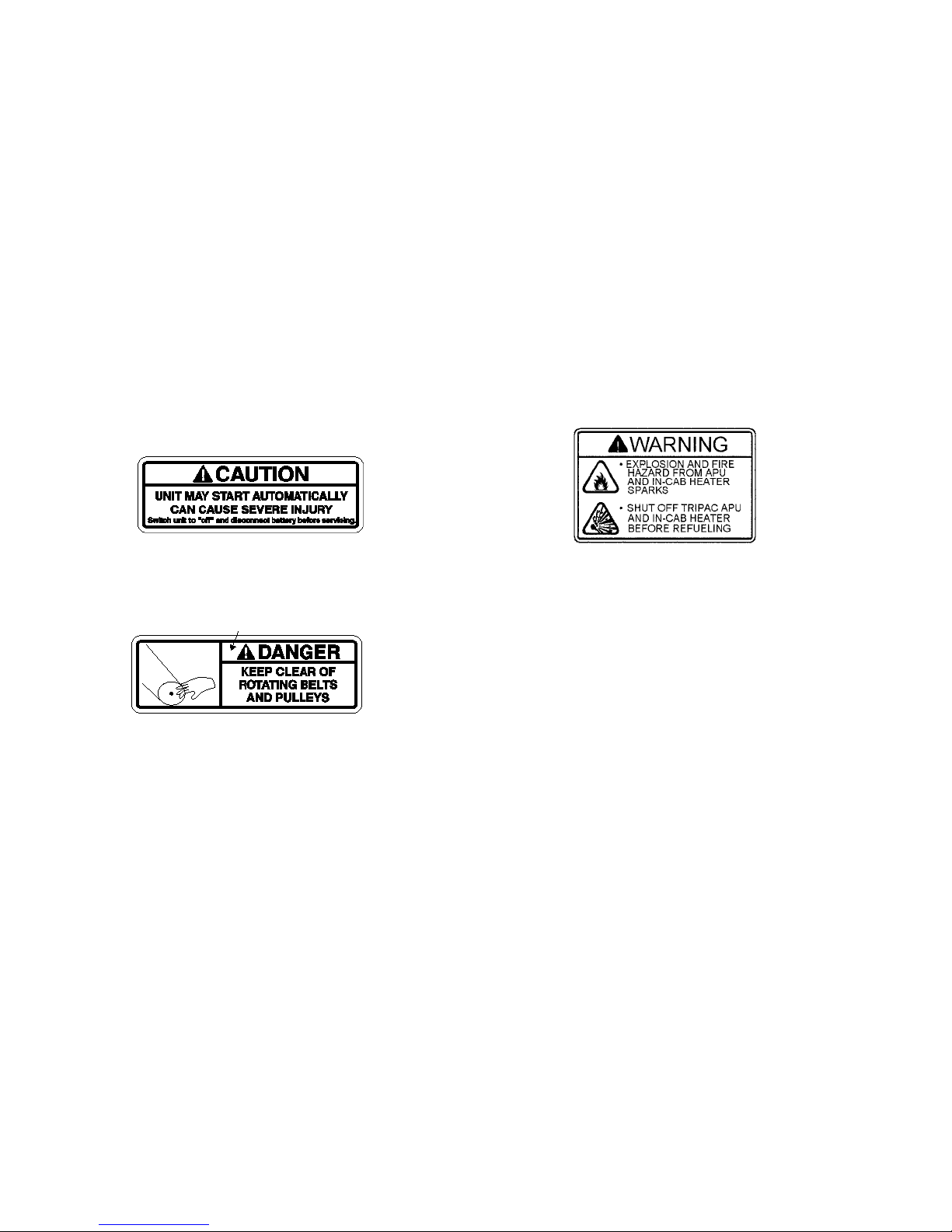
Figure 1: Caution - Unit May Start Automatically
Figure 2: Belt and Pulley Warning
Figure 3: Shut Off Before Fueling Warning
AMA647
AMA646
AMA690
Page 15

11
Unit Description
Introduction
The Thermo King TriPac Auxiliary Heating & Cooling
Temperature Management System allows drivers to reduce
unnecessary truck engine idling, conserve diesel fuel and save
money. TriPac provides truck engine preheating, battery
charging and truck cab sleeper compartment climate control.
By using TriPac, drivers can reduce fuel cost, rest comfortably
during stops and comply with local, state and federal anti-idle
laws. Reducing unnecessary truck engine idling also reduces
engine wear and extends engine maintenance intervals.
TriPac’s own diesel engine uses an automatic start/stop feature
for additional fuel efficiency.
TriPac’s two-cylinder diesel engine is EPA Tier 2 approved.
An automotive type air conditioning compressor is used for
sleeper compartment cooling. A fuel-fired air heater provides
sleeper compartment heat in cold conditions. Voltage sensing
automatically charges the truck batteries from TriPac’s 12-volt
alternator. Noise dampening construction assures quiet
operation. Truck engine preheating provides easier coldclimate starts by exchanging coolant between TriPac and the
truck engine. Optional Closed Loop Cooling allows the TriPac
to operate independently of truck engine coolant. An optional
inverter provides 120-volt power to operate on-board
appliances. The optional Arctic package aids truck engine
startups in cold weather by sensing low coolant temperature.
The TriPac is started to heat the coolant as required.
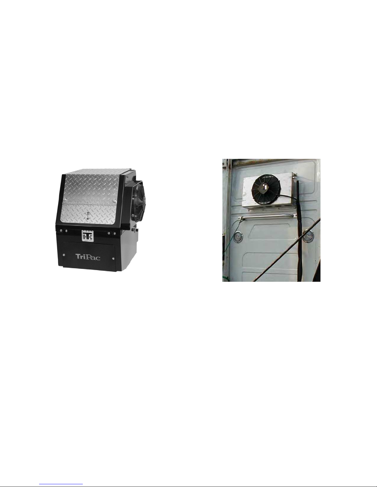
Figure 4: TriPac
AMA691
Page 16

Unit Description
12
Unit Features
• Easy to operate Human Machine Interface (HMI)
Controller
• Truck cab sleeper compartment cooling and heating for
driver comfort in all climates
• Truck engine preheating for easy starts in cold climates
• Truck battery charging with automatic low voltage sensing
• 7.5 hp 2 cylinder diesel engine - EPA Tier II
• Thermo King TM-15-XD compressor for air conditioning
• Diesel fuel-fired sleeper compartment air heater
• 65 amp 12 VDC alternator
• Noise-dampening construction for quiet operation
• Automatic start/stop operation for maximum fuel
efficiency
• Optional Standby Truck Integration
• Optional dash mounted Truck Integration Selector Switch
(select normal or standby operation)
• Optional Arctic Package
• Optional Closed Loop Cooling (CLC)
• Optional Extreme Arctic Package
• Optional 12 Vdc to 120 Vac 1800 Watt inverter for
on-board appliances
• Optional chrome plated exhaust pipe
• Optional stainless steel condenser shroud
• Optional Exhaust Diesel Particulate Filter (DPF)
TriPac System
The TriPac system includes several major components:
• An APU (auxiliary power unit)
• Condenser
• Evaporator
• Heater
• HMI Controller.
Page 17
Unit Description
13
Figure 5: TriPac APU
Auxiliary Power Unit
The TriPac APU contains the diesel engine, air conditioning
compressor, alternator and engine power switch.
Figure 6: Condenser
Condenser
The TriPac Air Conditioning Condenser is mounted on the
back of the truck cab.
AMA691
AMA550
Page 18
Unit Description
14
Figure 7: TriPac Evaporator and Air Ducts
(Evaporator installed under sleeper cab bunk)
Evaporator
The TriPac air conditioning Evaporator is typically installed
under the bunk in the truck cab sleeper compartment. Air ducts
from the Evaporator carry conditioned air to the sleeper
compartment
Figure 8: Heater
Heater
The TriPac Heater is typically installed in the cargo
compartment under the truck cab sleeper compartment. It
draws fuel from the truck’s diesel fuel tank and electric power
from the truck’s batteries.
AMA774
AMA653
AMA552
Page 19
Unit Description
15
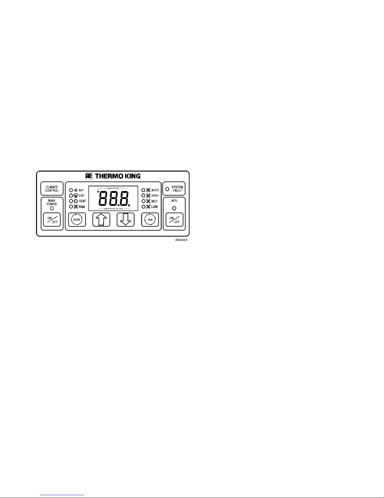
Figure 9: HMI Controller
HMI Controller
The TriPac HMI (Human Machine Interface) Controller is
installed in the truck cab, typically on a wall in the sleeper
compartment. It is easily accessible to the driver and controls
TriPac operation. Standard, typically used operating
parameters are enabled in the HMI Controller when TriPac is
installed. If necessary, HMI operating parameters can be
adjusted through programming by your Thermo King dealer.
Compressor
The TriPac air conditioning compressor is mounted in the
TriPac APU and is driven by the TriPac engine. Refrigeration
lines connect the compressor to the TriPac air conditioning
condenser on the back wall of the truck cab and the evaporator,
usually mounted under the truck sleeper compartment bunk.
Compressor operation is controlled by the TriPac Interface
Board. The Interface Board receives instructions from the HMI
Controller. The HMI Controller will instruct the Interface
Board to start the TriPac engine and energize the compressor
clutch when cab cooling is needed. The refrigeration system is
protected by high pressure and low pressure cutout switches.
Control Circuits
The control circuits operate on 12V DC supplied by the truck
batteries.
Page 20

Unit Description
16
Refrigerant
The TriPac uses R-134a refrigerant.
Protection Devices
The High System Pressure Cutout Switch is a normally
closed system pressure sensitive switch. On models
manufactured prior to 9/06, it is part of the binary pressure
switch, mounted on the receiver-drier, typically near the TriPac
condenser. On models manufactured during 9/06 and after, a
High Pressure Cutout Switch (HPCO) is located at the
receiver/drier.
If the discharge pressure rises above the switch’s opening
pressure, the switch opens the circuit to stop the unit and
generates an AcS Alarm Code. When the discharge pressure
falls below the switch’s closing pressure, the switch closes to
allow compressor operation.
The Low System Pressure Cutout Switch is a normally
closed pressure sensitive switch.
On models manufactured prior to 9/06, it is part of the binary
pressure switch, mounted on the receiver-drier, typically near
the TriPac condenser. On models manufactured during 9/06
and after, a Low Pressure Cutout Switch (LPCO) is installed at
the evaporator coil.
If the pressure falls below the switch’s opening pressure, the
switch opens the circuit to stop the compressor. When the
pressure rises above the switch’s closing pressure, the switch
closes to allow compressor operation.
Page 21
Unit Description
17
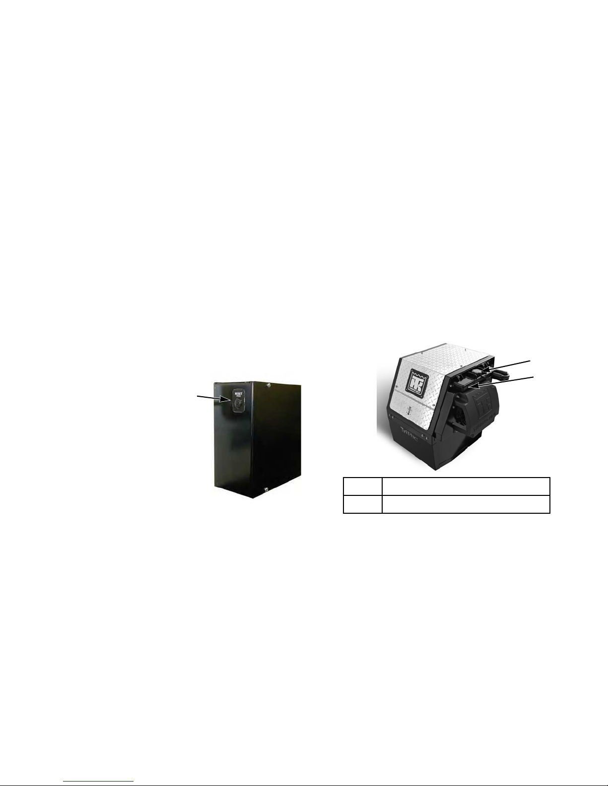
Engine Reset Switch
The engine is protected by a reset switch. When the reset
switch opens the engine will shut down and an “Eng” Alarm
Code will be displayed on the HMI. Typical causes for an open
engine reset switch are low oil pressure, high water
temperature or an engine start failure. The engine reset switch
is located on the side of the Interface Board control box
enclosure.
Closed Loop Cooling Option
The CLC option is designed for warm climate operation and
also to isolate the TriPac system from the tractor engine
coolant if desired. The TriPac will run independently of the
tractor engine coolant while providing battery charging and
cab comfort options.
On units with Interface Board
Revision 1.5 and earlier, the
button on the engine reset switch
pops out when the switch opens.
You can also feel it click and stay
in when you push it to reset it.
On units with Interface Board
Revision 1.6, the reset switch
button does not pop out when the
reset circuit opens. Also, you will
not feel a click when you push
the button to reset the circuit.
Figure 10: Engine Reset Switch
AMA618
1. Coolant Tank
2. Coolant Tank Sight Glass
Figure 11: Closed Loop Cooling Option
AMA783
1
2
Page 22

Unit Description
18
Fuses
Fuse Number Amp Rating Component Protected / Circuit
F1 30 Starter / 8S
F2 30 Glowplugs / H
F3 5 HMI Controller / —
F4 20 Cab Heater / RED
F5 5 Standby Switch / 2A
F6 1 Standby Integration / IGN
F7 40 Fuel Solenoid / 8DP
F8 7.5 Engine Switch / 8FET
F9 5 Engine Start Signal / 7X/7A
Page 23

Unit Description
19
Fuse Number Amp Rating Component Protected / Circuit
F10 15 Pre-cooler Fan / PCF
F11 20 Condenser Fan / 7CF
F12 20 Evaporator Fan / PWM1/PWM2/7D
F13 7.5 Compressor Clutch / 7CL
F14 5 Heater On / 26/YLW
F15 3 Voltage Sense / SEN
F16 50 Main Power / 2
F17 2 Ground / CH
F18 3 Hourmeter (Option) / 2
F19 3 Hourmeter (Option) / 8D
F20 3 Hourmeter (Option) / 26
F21 100 Supplemental Heater Contactor (Extreme Arctic Option) / SHR
Fuse Number Amp Rating Component Protected / Circuit
Page 24

Unit Description
20
F22 70 Supplemental Heater (Extreme Arctic Option) / SH
F23 30 Oil Pan Heater (Extreme Arctic Option) / OPH
Fuse Number Amp Rating Component Protected / Circuit
CAUTION: Use fuel suitable for the climate you operate in (see truck engine manufacturer’s recommendations).
Blending used engine oil with diesel fuel is not permitted in the TriPac system. It will plug the filters and will not allow
the air heater to run properly. Thermo King reserves the right to void all warranty on the unit.
Page 25

21
Manual Pretrip Inspection
(Before Starting the TriPac Unit)
Pretrip inspections are an important part of a preventative
maintenance program designed to minimize operating
problems and breakdowns. Perform this pretrip inspection
before every trip.
NOTE: Pretrip inspections are not intended to take the place
of regular maintenance inspections.
Engine: Check engine oil level. Check coolant level if
equipped with optional closed loop cooling. Coolant should be
visible in coolant tank sight glass.
Belts: Make sure the TriPac APU belts are in good condition
and adjusted to the proper tension. For more information about
belt tension, see the Specifications chapter.
Electrical: Check the electrical connections to make sure
they are securely fastened. Wires and terminals should be free
of corrosion, cracks, and moisture.
Structural: Visually inspect the unit for leaks, loose or
broken parts, and other damage.
Coils: Make sure the condenser, evaporator and pre-cooler
coils are clean and free of debris.
Heater: Check exhaust pipe and intake tube.
General: Listen for unusual noises and vibrations.
Page 26

Manual Pretrip Inspection (Before Starting the TriPac Unit)
22
Page 27

23
TriPac HMI Controller Description and Operation
The TriPac is operated using an HMI (Human Machine
Interface) Controller which is typically mounted on a wall in
the truck cab sleeper compartment. The HMI Controller
includes a display screen, operation keys and indicator LEDs.
Figure 12: HMI Controller
2
3
7
6
5
1
1. Display
2. HMI Controller Main Power
Key
3. Mode Key
4. Up and Down Keys
5. Fan Speed Key
6. APU System Key
7. System Fault Indicator
2
4
3
7
6
5
1
1. HMI Controller Display
2. HMI Controller Main Power Key
and LED
3. Mode Key
4. Up and Down Arrow Keys
5. Fan Speed Selector Key
6. APU On/Off Key and LED
7. System Fault LED
Page 28

TriPac HMI Controller Description and Operation
24
TriPac HMI Controller Description
HMI Controller Display
The HMI Controller Display is used to
indicate temperature setpoint, alarm
codes, hourmeter reading, and other
information. The LED indicator at lower
right will be illuminated when the sleeper
cab temperature setpoint is displayed.
The LED indicator at upper left will be
illuminated when the inside or outside
temperature is displayed..
Main Power Key
The HMI Controller Main Power Key is
used to turn the TriPac system on and off
from the sleeper compartment. The green
LED indicator is illuminated when the
TriPac system is turned on..
Mode Key
The HMI Controller Mode Key is used to
select the desired operating mode. When
the TriPac system is turned on the mode
will default to the setting last used. A/C
(air conditioning), Fan and Heat modes are
selected by pressing the Mode key. (“DEF”
is not used.) A Monitor (Null) mode will
occur when no LEDs are illuminated. This
allows the unit to monitor the battery
voltage, and optionally the coolant
temperature, without monitoring the truck
cab temperature.
Up and Down Arrow Keys
The HMI Controller Up and Down Keys
are used to raise and lower the temperature
setpoint in the display. Each press of the
Up or Down key will raise or lower the
setpoint temperature by one degree. The
display will scroll up or down if the Up or
1
2
1. Cab Setpoint
Temp LED
2. Inside/Outside
Temp LED
Page 29

TriPac HMI Controller Description and Operation
25
Down key is pressed continuously. The HMI
Controller setpoint temperature range is 50 to
90 degrees.
Fan Speed Key
The HMI Controller Fan Speed Key is used to
select the desired evaporator fan speed. When
the TriPac APU system is turned on, the fan
speed will default to the setting last used. High,
Medium and Low fan speeds are selected with
the Fan Key. Auto fan is currently not available.
APU System Key
The HMI Controller APU System Key is used
to enable the APU diesel power unit. The APU
must be ON to provide sleeper compartment air
conditioning, air circulation, truck battery
voltage sensing and engine coolant temperature
sensing. This key also allows access to the
diesel engine hourmeter reading. The APU
does not have to be On to operate the TriPac
sleeper compartment heater.
System Fault Indicator
This red indicator illuminates when an alarm
condition occurs and an alarm code is displayed.
Page 30

TriPac HMI Controller Description and Operation
26
Operating Modes
Air Conditioning Mode
If the HMI controller senses that the truck cab sleeper
compartment temperature is 5 F above setpoint, the APU
engine will start (if not already running) and the compressor
clutch will engage. The A/C system will operate for at least 15
minutes after the temperature in the sleeper compartment
reaches setpoint. This is to ensure that the truck battery is
sufficiently charged. The APU engine will shut down if the
sleeper compartment temperature setpoint and truck battery
voltage have been attained (and, when the optional Arctic
Package is installed, if the coolant temperature has been
attained).
Heat Mode
The air heater controls the sleeper cab temperature to the
setpoint entered in the HMI. If the APU is enabled, the
evaporator fans can be on to circulate more air, and battery
voltage sensing is enabled..
Fan Mode
The fans can be turned on for air circulation in the truck cab.
Fan speed is selected and battery voltage sensing is enabled.
The APU must be enabled..
Monitor (Null) Mode
The Monitor (Null) mode occurs when the HMI controller is
on, the APU system is enabled and no Mode or Fan LEDs are
illuminated (fans are off). Battery voltage sensing is enabled. If
the optional Arctic Package is installed, coolant temperature
sensing is enabled. Truck cab temperature sensing is not
enabled.
Page 31

TriPac HMI Controller Description and Operation
27
Engine On/Off Switch
The Engine On/Off Switch is located inside the TriPac APU
housing on the right side of the frame. This switch must be in
the On position for the TriPac engine to operate.
Figure 13: Engine On/Off Switch
DANGER: Always turn the TriPac Main Power
On/Off Key on the HMI Controller OFF while
refueling the truck. Fuel vapors could ignite if they
come in contact with TriPac electrical or heater
components.
WARNING: The unit may start automatically without
warning if the Engine On/Off Switch is in the On
position.
WARNING: Immediately stand clear when the
preheat buzzer sounds. This indicates that the engine
is preheating. If the engine is hot, preheat time will
only be a few seconds.
Use Tier 2 Photo
AMA695
Page 32

TriPac HMI Controller Description and Operation
28
TriPac HMI Controller Operation
Press HMI Controller Main Power Key
1. Press the Main Power Key. The green LED indicator will
be illuminated when the HMI Controller is turned on.
Figure 14: HMI Controller Main Power Key
Enable APU System
2. The Engine On/Off Switch (inside the TriPac APU) must
be on for the engine to run. Press the HMI Controller APU
Key to enable the diesel power unit and also enable sleeper
compartment air conditioning, air circulation, truck battery
voltage sensing and engine coolant temperature sensing.
The APU Key LED will be illuminated while the APU is
enabled. When the APU Key is initially pressed, the
TriPac unit engine hourmeter reading will be displayed.
(See next step.)
Figure 15: APU Key
AMA562
1
2
Page 33

TriPac HMI Controller Description and Operation
29
Engine Hourmeter Display
3. When the APU Key is initially pressed, the TriPac unit
engine hourmeter reading will be displayed. The display
will flash three screens, starting with “HrS” and followed
by “tXX” for thousands of hours and then “XXX” for
hundreds of hours. Example for 1,230 hours:
Figure 16: Engine Hour Meter Display
Select Mode of Operation
4. Press the HMI Mode Key to select the desired operating
mode. Select Air Conditioning, Heat or air circulation Fan
operation. (“DEF” is not used.) When the TriPac is first
started, the controller will default to the previous setting.
Press the Mode Key repeatedly to scroll through the
selections. The operating mode selected will be indicated
by an illuminated LED. A Monitor (Null) mode will occur
when no LEDs are illuminated. If heat is required, the
TriPac heater may operate while the TriPac APU engine is
off and the HMI Fan Speed Key is off (no LED
illuminated).
Figure 17: Mode Key
3
4
Page 34

TriPac HMI Controller Description and Operation
30
Select Fan Speed
5. Press the HMI Fan Speed Key to select the desired fan
speed. Select High, Medium or Low speed. When the
TriPac is first started, the HMI Controller will default to
the previous setting. The fan speed selected will be
indicated by an illuminated LED. (Auto fan speed is not
currently used.)
The TriPac heater will operate while the Fans are off (no
fan LED is illuminated – fan is in “Null”). If additional air
circulation in the truck cab sleeper compartment is
desired, the fans may be turned on by enabling the APU.
Figure 18: Fan Speed Key
Select Temperature Setpoint
6. Press the HMI Up or Down Keys to raise or lower the
temperature setpoint. Each time an Up or Down Key is
pressed, the display will increment up or down by one
degree. If a key is pressed continuously, the display will
scroll up or down. The setpoint will be changed to the
value shown in the display. The HMI setpoint temperature
minimum is 50 degrees and the maximum is 90 degrees.
7. The lower right LED in the HMI Display indicates that the
sleeper compartment temperature setpoint is displayed..
Figure 19: Up and Down Keys
5
6
7
Page 35

TriPac HMI Controller Description and Operation
31
NOTE: When the temperature in the sleeper compartment
has reached the heating or cooling setpoint, the TriPac may
shut down. This is normal operation. No alarm codes will be
displayed.
If other conditions also exist, such as low battery voltage or
low coolant temperature, the TriPac will continue to run.
When all conditions are satisfied
(sleeper compartment
heating or cooling temperature setpoint reached, minimum
battery voltage is present and minimum coolant temperature
is present [with the Arctic option]) the TriPac will shut down
.
The TriPac will restart if the TriPac system is on and any of
these conditions require a restart. (The truck’s ignition switch
must be in the Off or Accessory position.) No alarm codes will
be displayed during these normal operations.
System Fault Indicator
8. The HMI System Fault red indicator glows any time an
alarm condition occurs and an alarm code is displayed.
Figure 20: System Fault Indicator
8
Page 36

TriPac HMI Controller Description and Operation
32
Alarm Codes
TriPac HMI Controller alarm codes are:
•
Eng:
This code indicates that the that the “8” circuit has a
failure. This can be caused by an open engine reset switch
or the engine compartment On/Off Switch is in the Off
position. Typical causes for an open engine reset switch
are low oil pressure, high water temperature or a start
failure.
NOTE: If the unit is equipped with the optional DPF an
[Eng] code can be generated by the Regeneration switch
being placed in the "Off" position or a DPF shutdown
code. Verify the DPF Regeneration switch is in the
"On" position and check to see if there are any DPF
alarm codes.
•
AcS:
This code indicates that an abnormal air
conditioning system condition has occurred. Typical
causes are high discharge pressure or low system pressure.
•
ALt:
This code indicates that a charging system failure
has occurred. This code will occur if there is no alternator
output after 2 minutes of operation.
•
bAT:
This code indicates that the battery voltage is low.
To Clear Alarm Codes
Record the alarm code shown in the display. To clear an alarm
code, use the HMI Main Power Key to turn off the TriPac
system. Then resolve the condition that caused the alarm.
Check the engine reset switch. If the alarm tripped the switch,
the switch must be reset to allow the TriPac engine to be
restarted. The engine reset switch is located on the side of the
Interface Board control box enclosure.
Page 37

TriPac HMI Controller Description and Operation
33
Optional Standby Operation
The optional TriPac HMI Controller Standby Mode allows the
system to be controlled by an external source which is typically
the truck’s ignition system. This is used to disable the TriPac
system when the truck’s engine is running. The display will
show “Sby” when the controller is in this mode. During
Standby mode the controller is temporarily disabled and none
of the TriPac systems will operate. Voltage sensing and the
optional coolant temperature sensing functions are also
disabled while in this mode.
Figure 21: Standby Operation
Options Used With Standby Operation
Standby Truck Integration
When the truck’s ignition switch is in the Off or Accessory
position, the TriPac APU will operate normally if the APU
Engine On/Off switch and the TriPac HMI Controller Main
Power Key are On. If the truck’s ignition switch is in the On
position, the TriPac HMI Controller will be forced to Standby
Mode.
Truck Integration Selector
Switch
When the dash mounted Truck Integration
Selector Switch is in the Normal position,
the TriPac APU will operate the same as
with Standby Truck Integration above.
However, if the dash mounted Selector
Switch is in the Standby position, the APU
will be forced to Standby mode.
Page 38

TriPac HMI Controller Description and Operation
34
Page 39

35
Optional Power Inverter
Inverter Operation Warnings
A 12 volt dc to 120 volt ac inverter is available as an option for
TriPac. The inverter is normally connected directly to the truck
batteries.
Inverter features will vary, depending upon the brand and
model used. Typically, when the inverter detects an AC load, it
automatically turns on and converts dc to ac to power onboard
120 volt ac devices. If the TriPac is enabled and the inverter
DANGER: Do not use an inverter in life support or
health care applications where a malfunction or
failure of the inverter could cause failure of a life
support device or medical equipment or significantly
alter the performance of that equipment.
DANGER: Potentially lethal voltages exist within the
inverter as long as the battery supply is connected.
During any service work, the battery supply should be
disconnected.
DANGER: Do not connect or disconnect batteries
while the inverter is operating from the battery
supply. Dangerous arcing may result.
CAUTION: Protect against possible electrical shock
hazards. If the inverter is operated in wet or damp
conditions a user-supplied, portable GFCI (ground
fault circuit interruptor) must be connected between
each inverter receptacle and the equipment it powers.
CAUTION: You may experience uneven performance
results if you connect a surge suppressor, line
conditioner or UPS system to the output of the
inverter.
Page 40

Optional Power Inverter
36
draws truck battery voltage down below the voltage limit
established for the installation, the TriPac will start and attempt
to recharge the truck batteries back to the level specified. If the
TriPac is not enabled, the inverter could drain the truck
batteries below the level required to start the truck or the
TriPac.
Manufacturer’s instructions for the optional inverter are
provided separately. It is important to read and follow those
instructions for proper use of the inverter.
Page 41

37
Specifications
Engine Specifications
Engine TK 270 (Tier 2)
Fuel Type
Caution: Use fuel suitable for the climate you
operate in (see truck engine manufacturer’s
recommendations). Blending used engine oil
with diesel fuel is not permitted in the TriPac
system. It will plug the filters and will not allow
the air heater to run properly. Thermo King
reserves the right to void all warranty on the unit.
No. 2 Diesel fuel under normal conditions
No. 1 Diesel fuel is acceptable cold weather fuel
Oil Capacity: Crankcase & Oil Filter 4.5 quarts (4.3 liters), Fill to full mark on dipstick.
Fill the crankcase slowly so oil will not run into the
breather hose, thus filling up an open cylinder.
Leaving the dipstick out while adding engine oil
will vent the crankcase.
Page 42

Specifications
38
Oil Type* API Type CI-4 or better multigrade oil
API Synthetic Type CI-4 or better after first 1000
hours (optional)
API Type CJ-4 or better multigrade oil is required
for units equipped with the optional DPF (Diesel
Particulate Filter)
Oil Viscosity Multigrade Oil Ambient Temperature
5 to 104 F (-15 to 40 C): SAE 15W-40
-4 to 86 F (-20 to 30 C): SAE 10W-30
Engine rpm:
No Load Operation, compressor clutch disengaged
Under Load Operation, compressor clutch engaged
1850 rpm
1800 rpm
Engine Oil Pressure 50 psig (345 kPa) at rated output. 18 psig (128
kPa) at low idle.
Page 43

Specifications
39
Coolant System Capacity (TriPac engine only) 0.6 quarts (0.6 liters)
2.75 quarts (2.6 liters) with Closed Loop Cooling
Engine Coolant Type: Conventional Conventional coolant (antifreeze) is green or
blue-green. Units equipped with conventional
coolant do not have an ELC nameplate on the
expansion tank.
Make sure you know what type of coolant is in your
unit. Do not mix conventional coolant and ELC.
ELC (Extended Life Coolant) ELC is red. Units equipped with ELC have an
ELC nameplate on the expansion tank (see
“Safety Decals and Locations”).
Use a 50/50 concentration of any of the following
equivalents:
Texaco ELC (16445, 16447)
Havoline Dex-Cool® (7994, 7995, 7997, 7998)
Havoline XLC for Europe (30379, 33013)
Shell Dexcool® (94040)
Shell Rotella (94041)
Saturn/General Motors Dex-Cool®
Caterpillar ELC
Detroit Diesel POWERCOOL® Plus
Engine Thermostat 180 F (82 C)
Page 44

Specifications
40
Radiator Cap Pressure, Closed Loop Cooling
10 psig (69 kPa)
Drive Belts to compressor, 12 V alternator, water pump
Compressor
Compressor TM-15-XD
Compressor Oil Charge 8 oz. (236.5 ml)*
Compressor Oil Type (R134a
Refrigerant Used)
Oil Viscosity
100 Polyalkylene glycol (PAG 100) TK P/N 203-502
R-134a Refrigeration System
Refrigerant Charge 1.2 lbs. (0.54 Kg) minimum, 2.0 lbs (0.9 Kg)
maximum.
Correct system charge varies, depending upon
installation and refrigeration line lengths.
Page 45

Specifications
41
Fuses
Component Protected / Circuit Voltage Amp
F1 Starter/8S 12 30
F2 Glowplugs/H 12 30
F3 HMI Controller / — 12 5
F4 Cab Heater/RED 12 20
F5 Standby Switch/2A 12 5
F6 Standby Integration/IGN 12 1
F7 Fuel Solenoid/8DP 12 40
F8 Engine Switch/8FET 12 7.5
F9 Engine Start Signal/7X/7A 12 5
F10 Pre-cooler Fan/PCF 12 15
F11 Condenser Fan/7CF 12 20
F12 Evaporator Fan / PWM1/PWM2/7D 12 20
F13 Compressor Clutch / 7CL 12 7.5
Page 46

Specifications
42
F14 Heater On / 26/YLW 12 5
F15 Voltage Sense / SEN 12 3
F16 Main Power / 2 12 50
F17 Ground / CH 12 2
F18 Hourmeter (Option) / 2 12 3
F19 Hourmeter (Option) / 8D 12 3
F20 Hourmeter (Option) / 26 12 3
F21 Supplemental Heater Contactor
(Extreme Arctic Option) / SHR
12 100
F22 Supplemental Heater (Extreme Arctic
Option) / SH
12 70
F23 Oil Pan Heater (Extreme Arctic
Option) / OPH
12 30
FL1
(Prior To
9/06)
Fusable Link, 20 Gauge, Voltage
Sensing Wire
Page 47

Specifications
43
FL2
(Prior To
9/06)
Fusable Link, 12 Gauge, APU Main
Power
Belt Tension
Field Reset
Engine/Compressor/Alternator Belt The belt tension should be set at 95 lbs force.
A deflection of 1/4” between the alternator and
compressor (longest free span of belt) may be used if a
guage is not available to test tension.
Page 48

Specifications
44
Truck Sleeper Compartment Heater (D2)
Heat Output (±10%)
7,500 BTU/hr Boost (2.2 kW)
6,150 BTU/hr High (1.8 kW)
4,100 BTU/hr Medium (1.2 kW)
2,900 BTU/hr Low (0.85 kW)
Current at 12v (±10%) 8.3 amps - Start
2.8 amps - Boost
1.9 amps - High
1.0 amps - Medium
0.7 amps - Low
Fuel Consumption (±10%) Boost 0.07 gal/hr (0.28 liter/hr.)
High 0.06 gal/hr (0.23 liter/hr.)
Medium 0.04 gal/hr. (0.14 liter/hr.)
Low 0.03 gal/hr (0.10 liter/hr.)
Air Flow (±10%) 48 cfm Boost
40 cfm High
27 cfm Medium
19 cfm Low
Page 49

Specifications
45
Motor Speed 800 ± 140 RPM - Boost
4000 ± 120 RPM - High
2800 ± 80 RPM - Medium
2000 ± 60 RPM - Low
600 ± 20 RPM - Adjustment in circulation mode with
temperature sensor, internal.
0 RPM - Adjustment in fresh air mode with temperature
sensor, external.
4800 ± 140 RPM - Ventilation
Page 50

Specifications
46
Truck Sleeper Compartment Heater (D4 - Option)
Heat Output (±10%) 13,600 BTU/hr Boost (4.0 kW)
10,200 BTU/hr High (3.0 kW)
6,800 BTU/hr Medium (2.0 kW)
3,400 BTU/hr Low (1.0 kW)
Current at 12v (±10%) 8.3 amps - Start
3.3 amps - Boost
2.0 amps - High
1.1 amps - Medium
0.6 amps - Low
Fuel Consumption (±10%) Boost 0.13 gal/hr (0.51 liter/hr.)
High 0.10 gal/hr (0.38 liter/hr.)
Medium 0.07 gal/hr. (0.25 liter/hr.)
Low 0.03 gal/hr (0.13 liter/hr.
Air Flow (±10%) 85 cfm Boost
69 cfm High
50 cfm Medium
30 cfm Low
Page 51

Specifications
47
Motor Speed 4400 ± 130 RPM - Boost
3600 ± 100 RPM - High
2800 ± 80 RPM - Medium
1600 ± 50 RPM - Low
600 ± 20 RPM - Adjustment in circulation mode with
temperature sensor, internal.
0 RPM - Adjustment in fresh air mode with temperature
sensor, external.
3600 ± 100 RPM - Ventilation
Page 52

Specifications
48
Optional Power Inverter
1800 Watts; see manufacturer’s specifications
Optional Extreme Arctic Package Components
Approximate
Current Draw
(Amps) at 12.5
Vdc
Approximate
Resistance—
(Ohms)
Coolant Heater (800 Watts) 50 0.25
Oil Pan Heater (300 Watts) 19 0.65
Supplemental Heater Contactor Coil 13.5
NOTE: Disconnect components from unit circuit to check resistance.
Page 53

49
Maintenance Inspection Schedule
Pre-Trip 500 Hrs Annual
2,000 Hrs
Inspect/Service These Items
ENGINE
• • • Check engine oil level.
• • • If equipped with Closed Loop Cooling option: Check coolant level;
coolant should be visible in coolant tank sight glass.
• • • Inspect belts for condition and proper tension.
• • • Listen for unusual noises, vibrations, etc.
• • Check air cleaner hose for damage.
• • Inspect air cleaner. Change as needed, or annually.
• • Inspect fuel pre-filter. Change as required or annually.
• Change fuel filter. Thermo King brand fuel filter is required.
• Drain water from fuel tank and check vent.
• • Check and adjust engine speed.
• • Check condition of engine mounts.
Page 54

Maintenance Inspection Schedule
50
• Maintain year-round anti-freeze protection at –30° F (-34° C).
Change coolant every two years, or with truck coolant. For units with
optional Closed Loop Cooling system and ELC (red) engine coolant,
change ELC coolant every 5 years or 12,000 hours.
• Adjust engine valves.
- - - Test fuel injection nozzles at least every 3,000 hours. (Based on EPA
40 CFR Part 89.)
ENGINE OIL CHANGE INTERVALS
(Change oil and filters hot)
1,000
Hour
Intervals
1,000 Hour Interval - Oil change interval is every 1,000 hours of
operation only when using a Thermo King brand oil filter
and CI-4 or
better oil. Units with optional DPF require CJ-4 or better oil.
•500 Hour
Intervals
500 Hour Interval - Oil change interval is every 500 hours of
operation when using any other brand oil filter and CI-4 or better oil.
Units with optional DPF require CJ-4 or better oil.
IMPORTANT: Fill the crankcase slowly so oil will not run into the
breather, thus filling up a cylinder with an open valve. Leaving the
dipstick out while adding oil will ventilate the crankcase.
Pre-Trip 500 Hrs Annual
2,000 Hrs
Inspect/Service These Items
Page 55

Maintenance Inspection Schedule
51
ELECTRICAL
• • Check operation of protection shutdown circuits.
• • Check alternator voltage.
• Check alternator bearings. See Note 1
• • Inspect battery terminals.
• • Inspect electrical connections.
• • Inspect wire harness for rubbing or damage.
• • Check electric condenser, evaporator and pre-cooler fans.
Note 1 - With belt removed spin alternator by hand. Listen for noise and ensure that bearings roll
freely.
Pre-Trip 500 Hrs Annual
2,000 Hrs
Inspect/Service These Items
Page 56

Maintenance Inspection Schedule
52
STRUCTURAL
• • • Visually inspect unit for fluid leaks (coolant, oil, refrigerant).
• • • Visually inspect unit for damaged, loose or broken parts.
• • Inspect, clean and (if necessary) replace evaporator air filter. It may
be necessary to check or replace it more often if conditions require it.
• • Inspect evaporator drain valves (kazoos) to ensure that they are in
place, in good condition and are sealing.
• Steam clean condenser coil, APU pre-cooler coil. Do not bend over
coil fins.
• Blow out evaporator coil and evaporator water drains with air. Do not
bend over coil fins.
• Check APU mounting bolts and brackets for cracks. damage and
poor aligment.Verify tightness and torque to 100 ft/lbs (135.6 N•m) for
the claw mount, or 200 ft/lbs (271.2 N•m) for the direct frame mount.
Pre-Trip 500 Hrs Annual
2,000 Hrs
Inspect/Service These Items
Page 57

Maintenance Inspection Schedule
53
A/C SYSTEM
• • Check refrigerant level.
• • Check refrigerant lines for rubbing or damage.
HEATER
• • • Start and run for at least 20 minutes each month.
• • • Inspect combustion air intake tube and exhaust pipe for restrictions
or blockage.
• • • Inspect the ducting, the air intake screen and air outlet for restrictions
or blockage.
• Remove the glow pin and inspect for carbon build up. Clean.
• Remove the glow pin screen and inspect for carbon build up.
Replace.
• Change fuel pump screen.
Pre-Trip 500 Hrs Annual
2,000 Hrs
Inspect/Service These Items
Page 58

Maintenance Inspection Schedule
54
Page 59

55
TriPac Warranty
Terms of the Thermo King Warranty are available on request.
Please reference document TK 50046 for the Thermo King
TriPac Warranty.
Page 60

Tri Pac Warranty
56
Page 61

Serial Number Locations
57
Serial Number Locations
APU: Unit nameplate is located on front lower edge of APU
housing frame (APU cover must be removed to view the
nameplate).
Engine: Nameplate located on the top of the engine. The
engine is mounted in the TriPac APU housing.
Compressor: Nameplate located on compressor body. The
engine driven compressor is located in the TriPac APU
housing.
Page 62

Serial Number Locations
58
Page 63

59
TriPac Glossary
This glossary is published for informational purposes only and
the information being furnished herein should not be
considered as all-inclusive or meant to cover all contingencies.
NOTE: Additional terms not found in the glossary may be
located in the index section of this manual.
APU: Auxiliary Power Unit.
ambient air temperature: Temperature of the air
surrounding an object.
amp: Abbreviation for ampere. The basic measuring unit of
electrical current.
Btu (british thermal unit): The quantity of heat required to
raise the temperature of one pound of water by one degree
Fahrenheit. 1 Btu = 252 calories.
Celsius: The metric unit of temperature measurement. The
preferred alternate to the term centigrade. Abbreviated “C.”
centigrade. See Celsius.
CFC: Chlorofluorocarbon. A chlorine-based refrigerant
consisting of chlorine, fluorine and carbon. Example: R12. In
many countries it is illegal to release this type of refrigerant to
the atmosphere because chlorine damages the earth’s
atmosphere. CFC refrigerants are not used in modern Thermo
King units.
circuit breaker: A thermal device that automatically
interrupts an electrical circuit when the current in the circuit
exceeds the predetermined amperage rating of the breaker. See
amp.
coil: A cooling or heating element made of pipe or tube,
formed into a helical or serpentine shape, that may be equipped
with thin metal fins to aid heat transfer.
compressor: The refrigeration component that compresses
refrigerant vapor and creates refrigerant flow.
condenser: An arrangement of tubing in which the
vaporized and compressed refrigerant is liquefied as heat is
removed.
Page 64

TriPac Glossary
60
cycles per second: See Hertz.
dehydrator: A device used to remove moisture from
refrigerant. Also called a drier.
discharge air temperature: The temperature of air leaving
the evaporator.
drier: See dehydrator.
evaporator: The part of the refrigeration system that absorbs
heat during the cooling cycle.
F: See Fahrenheit.
Fahrenheit: A unit of temperature measurement used in the
United States. Abbreviated “F.”
freeze up: 1) Failure of a refrigeration system to operate
normally due to moisture in the refrigerant and the formation
of ice at the expansion valve. The expansion valve may be
frozen shut or open, causing improper unit operation in either
case. 2) The formation of a solid ice mass over the evaporator
coil reducing air flow.
fuse: An electrical safety device (typically a cartridge)
inserted into an electrical circuit. It contains material that will
melt or break when the current is increased beyond a specific
value. When this occurs, the circuit is opened and electrical
current flow is stopped.
fusible link: An electrical safety device (typically a short
piece of wire) inserted into an electrical circuit. The wire melts
or breaks when the current is increased beyond a specific
value. When this occurs, the circuit is opened and electrical
current flow is stopped.
HCFC: Hydrochlorofluorocarbon. A chlorine-based
refrigerant containing hydrogen, chlorine, fluorine and carbon.
Example: R22. Because chlorine damages the earth’s
atmosphere, in many countries, it is illegal to release this type
of refrigerant to the atmosphere. HCFC refrigerants are not
used in modern Thermo King units.
Hertz: A unit of frequency equal to one cycle per second.
Abbreviated “Hz.”
HFC: A refrigerant consisting of hydrogen, fluorine and
carbon. Examples: R134a and 404A. HFC refrigerants contain
no chlorine and are, therefore, considered “safe” for the
environment.
Page 65

TriPac Glossary
61
high pressure relief valve: A safety valve on the
refrigeration system that allows refrigerant to escape from the
system if pressure exceeds a predetermined value.
hp (horsepower): A unit of power equivalent to 746 watts
or 550 foot-pounds per second.
HPCO (High Pressure Cut Out Switch): A
pressure-operated switch that opens to stop unit operation
when discharge pressure reaches a predetermined maximum.
kPa: Kilopascals
. A metric unit of pressure. 1 kPa = 0.01 bar =
0.145 psi.
LPCO (Low Pressure Cut Out Switch): A
pressure-operated switch that opens to stop unit operation
when suction pressure reaches a predetermined minimum.
no. 1 diesel fuel: A grade of diesel fuel formulated to
prevent “jelling” in low ambient temperatures.
no. 2 diesel fuel: A grade of diesel fuel formulated for
moderate to warm ambient temperatures.
ohm: An electrical unit measuring the amount of resistance
(opposition to the current flow) in an electrical circuit.
pre-heat: The heating of diesel engine glow plugs prior to
start-up. Some engines use an intake manifold heater rather
than glow plugs.
pre-trip inspection: Checking the operation of a
refrigeration system before loading.
psi: Pounds per square inch. A unit of pressure.
1 psi = 0.069 bar = 6.89 kPa.
psig: Pounds per Square Inch Gauge. Pressure in pounds per
square inch as displayed by a gauge calibrated to zero when
open to the atmosphere.
receiver tank: A refrigerant storage device included in
nearly all Thermo King units.
refrigerant: The medium of heat transfer in a refrigeration
system which absorbs heat by evaporating at a low temperature
and releases heat by condensing at a higher temperature.
refrigerant oil: A special oil used to lubricate compressors in
refrigeration systems.
rpm: Revolutions per minute.
Page 66

TriPac Glossary
62
setpoint: The temperature selected on a thermostat or
microprocessor controller. This is normally the desired box
temperature.
short cycling: When a refrigeration unit cycles between the
heat and cool modes more often than normal.
sight glass: A system component that permits visual
inspection of oil or refrigerant level and condition.
Vac (volts alternating current): An electric current that
reverses direction at regularly recurring intervals.
Vdc (volts direct current): An electric current that flows in
one direction only and is constant in value.
volts: The basic measuring unit of electrical potential.
watt: The basic measuring unit of electrical power.
Page 67

63
Emergency Cold Line
If you can’t get your rig rolling, and you have tried the Thermo
King North American Service Directory (available from any
Thermo King dealer) to reach a dealer without success, then
call the Toll Free Emergency Cold Line Number
(888) 887-2202.
The answering service at the factory will assist you in reaching
a dealer to get the help you need. The Cold Line is answered 24
hours a day by personnel who will do their best to get you
quick service at an authorized Thermo King Dealer.
AKB12
Page 68

Recover Refrigerant
64
Recover Refrigerant
At Thermo King, we recognize the need to preserve the environment
and limit the potential harm to the ozone layer that can result from
allowing refrigerant to escape into the atmosphere.
We strictly adhere to a policy that promotes the recovery and limits
the loss of refrigerant into the atmosphere.
In addition, service personnel must be aware of Federal regulations
concerning the use of refrigerants and the certification of technicians.
For additional information on regulations and technician certification
programs, contact your local THERMO KING dealer.
Page 69

65
CALIFORNIA
Proposition 65 Warning
Diesel exhaust is a chemical known to
the State of California to cause cancer.
Page 70

66
Page 71

Page 72

Ingersoll Rand’s Climate Solutions sector delivers energy-effi cient HVACR solutions for
customers globally. Its world class brands include Thermo King, the leader in transport
temperature control and Trane, a provider of energy effi cient heating, ventilating and
air conditioning systems, building and contracting services, parts support and advanced
controls for commercial buildings and homes.
©2011 Ingersoll-Rand Company
Printed in U.S.A.
 Loading...